ADC Telecommunications PRSMAW4A FlexWave™ Prism - AWS 40 Watt User Manual 77073
ADC Telecommunications Inc FlexWave™ Prism - AWS 40 Watt 77073
UserManual.wiki
>
ADC Telecommunications
>
PRSMAW4A User Manual
>
User manual 3
Contents
1.
User manual 1
2.
User manual 2
3.
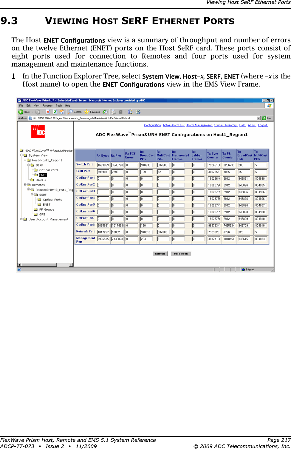
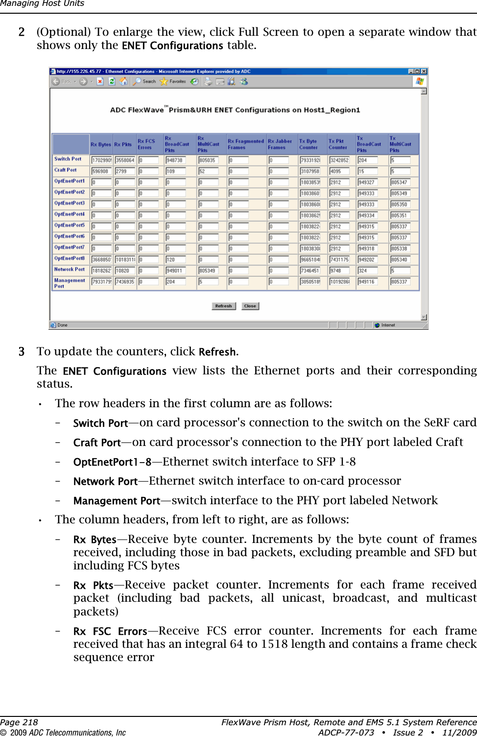
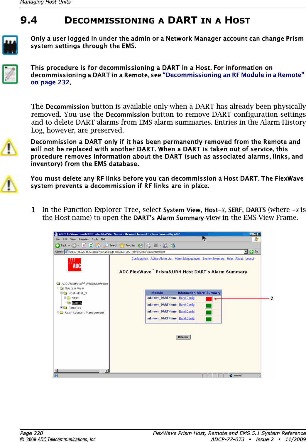
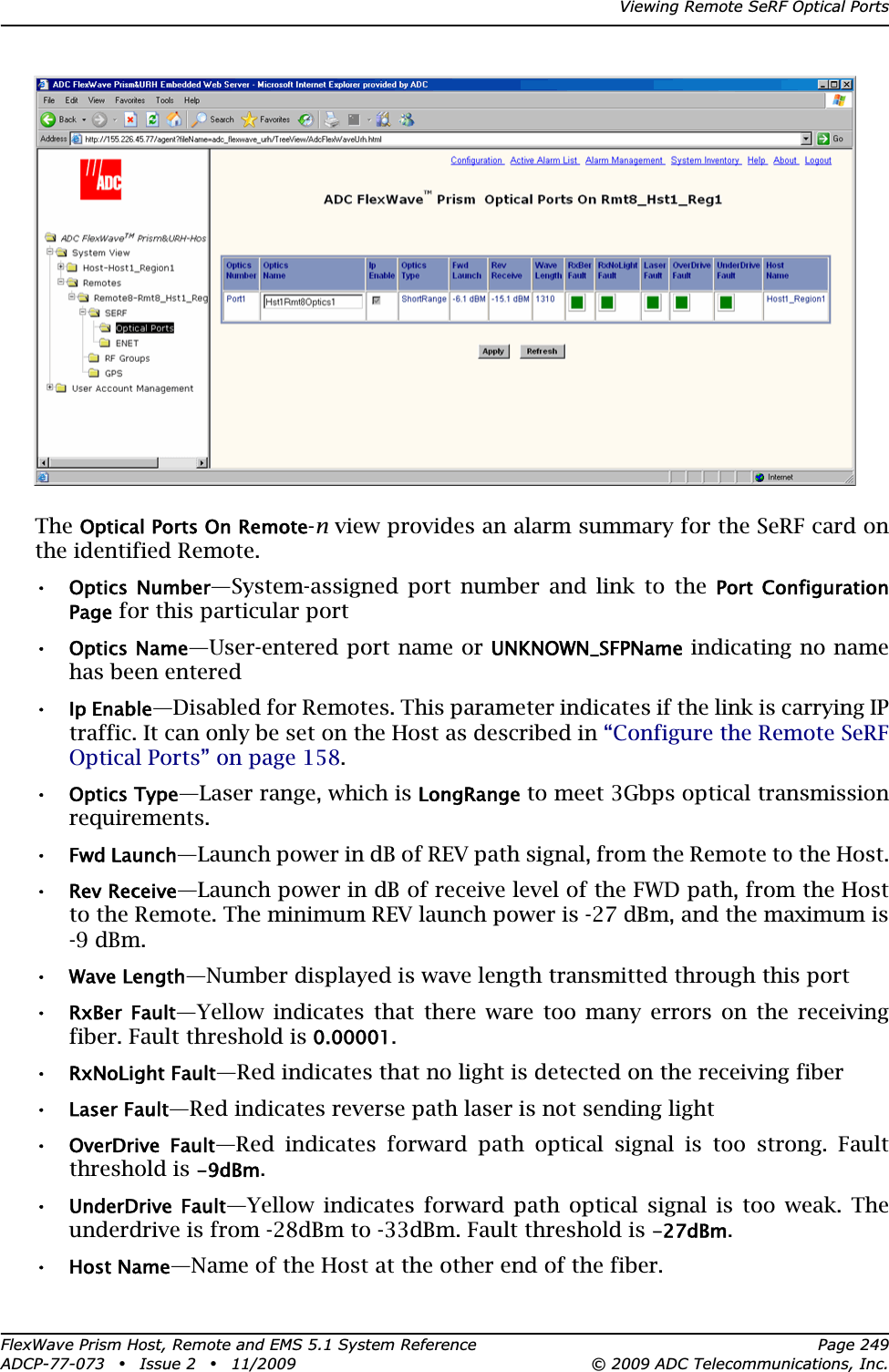
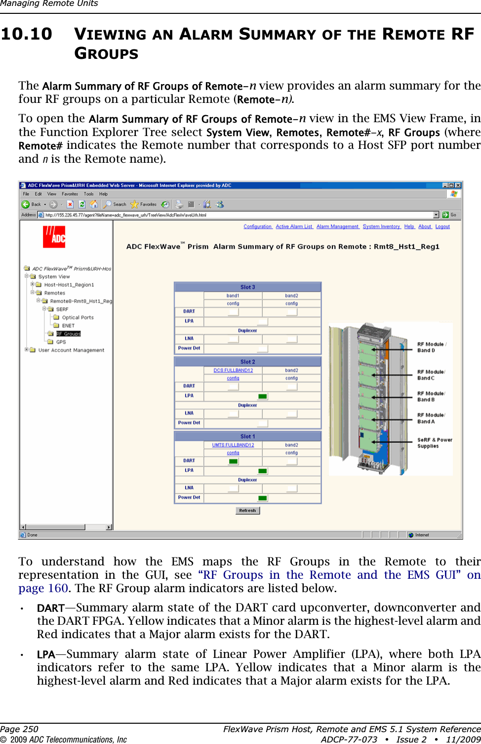
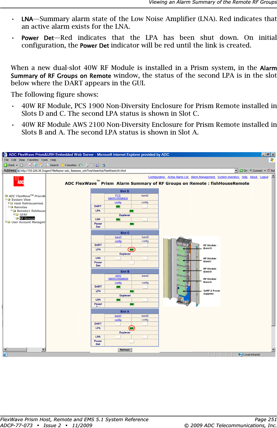
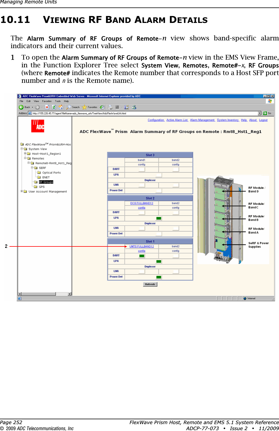
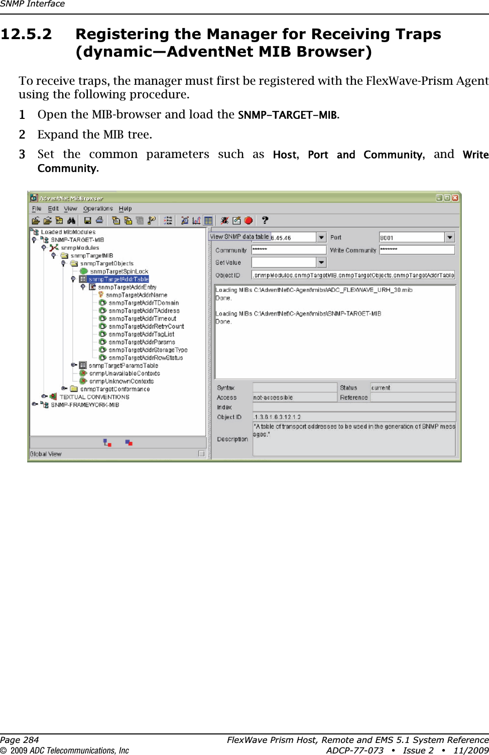
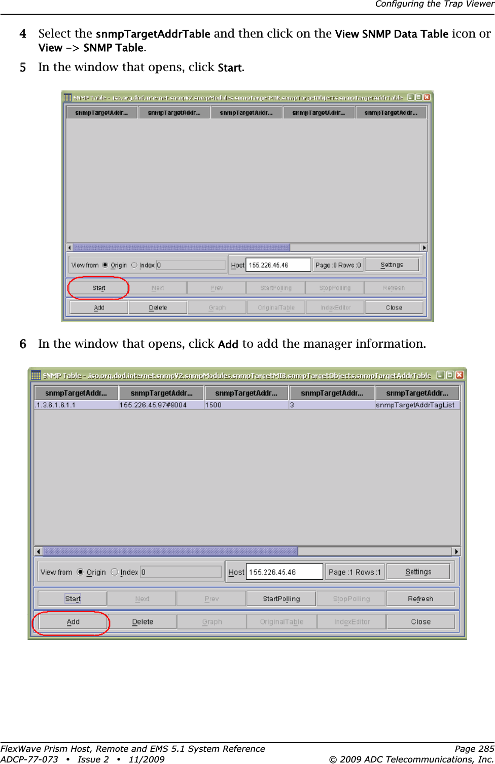
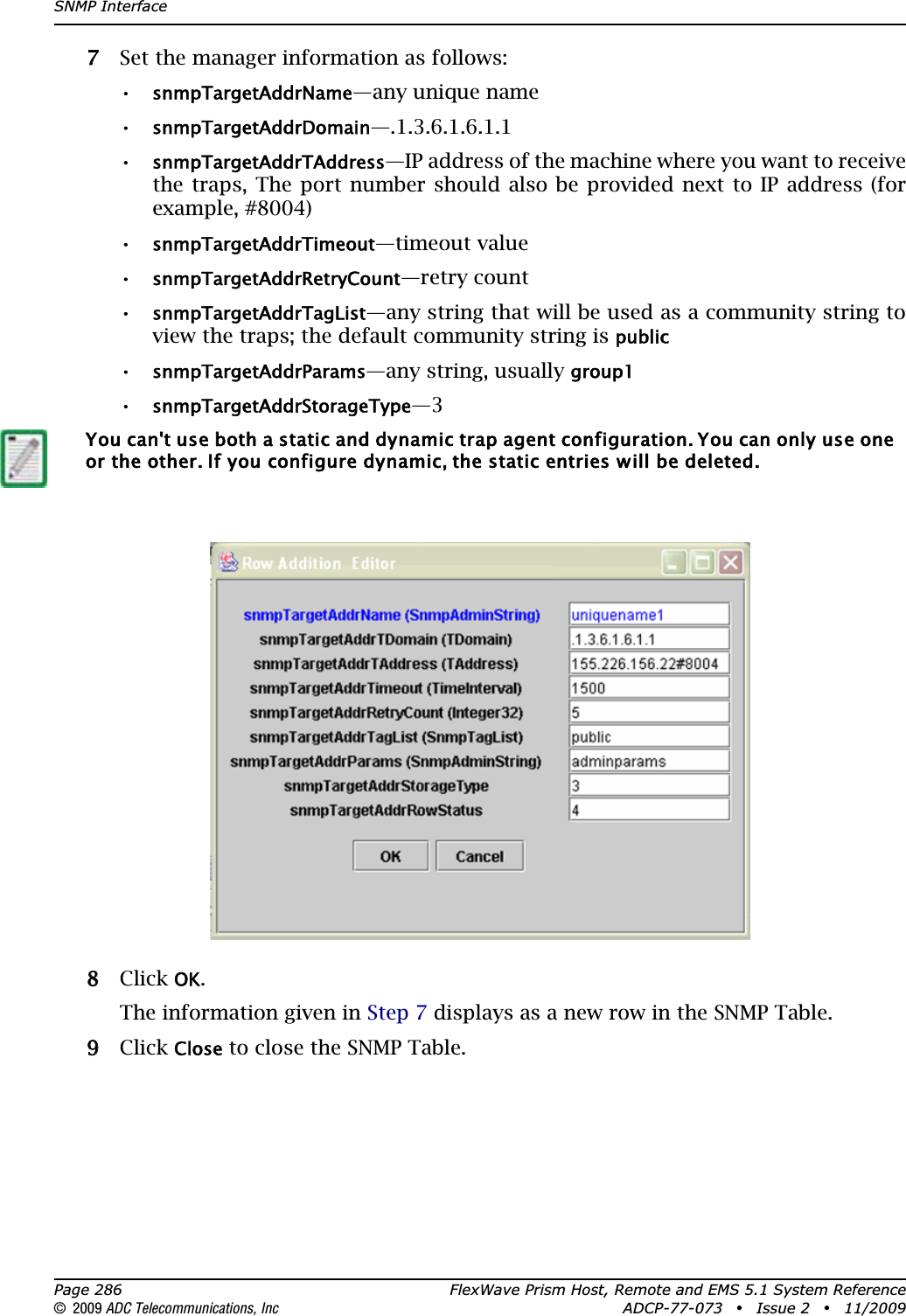
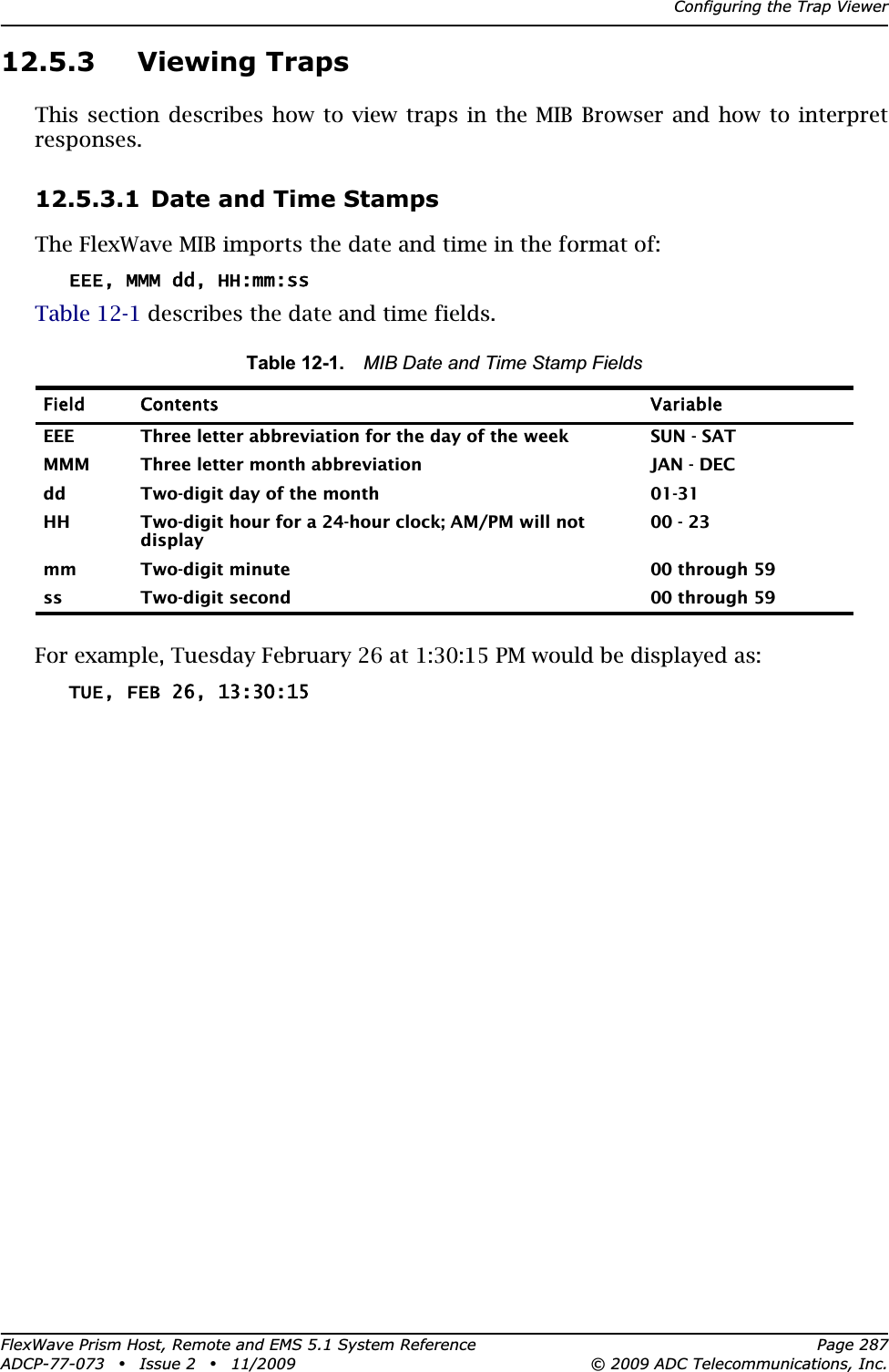
User manual 3
User manual 3
Navigation menu
Upload a User Manual
Namespaces
Wiki Guide
HTML
PDF
Info
Views
User Manual
Discussion / Help
Navigation