ADC Telecommunications PSM0850M FlexWave Prism HDM 850 MHz MIMO User Manual Installation manual
ADC Telecommunications Inc FlexWave Prism HDM 850 MHz MIMO Installation manual
Installation manual
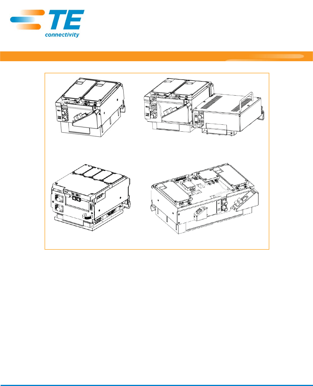
Dual-Band Dual-Slot RF Module
Single-Slot RF Module
Legacy Dual-Slot 40W RF Module
HDM RF Module
FlexWavePrismandSpectrum
SoftwareRelease8.1.4.7
ReleaseNotes
TECP‐77‐141∙Issue6∙July2014
TEConnectivity,TEandTEconnectivity(logo)FlexWave,InterReach,InterReachFusionandInterReachUnisonaretrademarks.
Allotherlogos,productsand/orcompanynamesreferredtohereinmightbetrademarksoftheirrespectiveowners.
Theinformationgivenherein,includingdrawings,illustrationsandschematicswhichareintendedforillustrationpurposesonly,isbelievedtobereliable.However,TE
Connectivitymakesnowarrantiesastoitsaccuracyorcompletenessanddisclaimsanyliabilityinconnectionwithitsuse.TEConnectivity'sobligationsshallonlybeas
setforthinTEConnectivity'sStandardTermsandConditionsofSaleforthisproductandinnocasewillTEConnectivitybeliableforanyincidental,indirector
consequentialdamagesarisingoutofthesale,resale,useormisuseoftheproduct.UsersofTEConnectivityproductsshouldmaketheirownevaluationtodetermine
thesuitabilityofeachsuchproductforthespecificapplication.
ThismanualprovidestheinformationyouneedtoinstallTEConnectivityFlexWavePrism®RFModulesintoa
PrismRemoteUnit(PRU).
InstallationinstructionsareprovidedforthefollowingPrismRemoteUnitRFModules:
•Single‐BayRFModules,whichincludestheHDMRFModules
•Dual‐BayRFModules
–Dual‐BandRFModules
–Legacy40WRFModules.

Page2FlexWavePrismRemoteUnitRFModuleInstallationGuide
©2014TEConnectivity TECP‐77‐141Issue6•300001744178RevF•July2014
TABLEOFCONTENTS
DocumentOverview ...........................................................................................................................................................................................3
RevisionHistory.......................................................................................................................................................................................................5
DocumentCautionsandNotes ...............................................................................................................................................................................5
AbbreviationsUsedinthisGuide............................................................................................................................................................................5
OverviewofRFModulesforPrismRemoteUnits ................................................................................................................................................6
RFModuleDARTs....................................................................................................................................................................................................7
RFModuleTypes.....................................................................................................................................................................................................8
Single‐andDual‐BayRFModuleswithClassicorSuperDARTs .......................................................................................................................8
HDMRFModules ............................................................................................................................................................................................9
LegacyDual‐Bay40WRFModules ................................................................................................................................................................10
RFModuleComponents .................................................................................................................................................................................... 11
DuplexerandLowNoiseAmplifier........................................................................................................................................................................12
LinearPowerAmplifiers ........................................................................................................................................................................................12
DigitalProcessingModule.....................................................................................................................................................................................13
UnderstandingtheRFModuleCables................................................................................................................................................................13
PowerCableConnection .......................................................................................................................................................................................13
LVDSCableConnections........................................................................................................................................................................................13
RFCableConnections............................................................................................................................................................................................14
RFCableRules ...............................................................................................................................................................................................14
RFModuleCablesforSingle‐Card,Dual‐Card,andHDMRFModules ..........................................................................................................15
RFModuleCablesforDual‐BayInstallations ................................................................................................................................................16
RFGroupAssignmentsforPRUs ...........................................................................................................................................................................17
InstalltheRFModule(s) ....................................................................................................................................................................................20
SafetyPrecautions.................................................................................................................................................................................................20
GuardagainstDamagefromElectro‐StaticDischarge ..........................................................................................................................................21
UnpackandInspecttheRFModule ......................................................................................................................................................................21
RemoveReleaseLinersfromtheRFModule ........................................................................................................................................................21
Dual‐BayModulesOnly—RemovetheModuleBayShelf.....................................................................................................................................23
InstalltheRFModuleintothePrismRemoteChassis...........................................................................................................................................24
SecureRFModuleLatches ....................................................................................................................................................................................32
ConnectLatchesonSingle‐BayandHDMRFModules .................................................................................................................................32
ConnectLatchesonDual‐BayRFModules....................................................................................................................................................33
LatchesonLegacyDual‐Bay40WRFModules..............................................................................................................................................34
VerifythattheRFModuleMountingHookisEngaged.................................................................................................................................34
ConnecttheRFModuleCables .............................................................................................................................................................................34
ConnectingCablesinaSingle‐BayRFModuleInstallation ...........................................................................................................................35
ConnectingCablesinaDual‐BayRFModuleInstallation..............................................................................................................................38
PowerontheRFModule.......................................................................................................................................................................................42
FlexWaveNotchFilter(FWP‐SPRINTFILTER) ......................................................................................................................................................43
StandardsCertification...................................................................................................................................................................................... 45
AccessingUserDocumentationontheTECustomerPortal................................................................................................................................46
ContactingTEConnectivity................................................................................................................................................................................47

FlexWavePrismRemoteUnitRFModuleInstallationGuide Page3
TECP‐77‐141Issue6•300001744178RevF•July2014 ©2014TEConnectivity
DOCUMENTOVERVIEW
Table1liststheRFModulesthatthisinstallationguidesupports.
Table1.FlexWavePrismRFModulesSupportedinthisInstallationGuide
CatalogNumber Description
High‐DensityModule(HDM);SingleBay
FWP‐441T841MOD DUAL20WSMR800/PCS1900
FWP‐8416000MOD 20WPCSModule,Non‐Diversity,HDM,SingleBay
FWP‐84MT000MOD Dual20W1900PCS,RFModule,MIMO,Single‐Bay
FWP‐881T000MOD HDMPCSBand2&2540WSISO,Single‐Bay
FWP‐A416000MOD 20WAWSModule,Non‐Diversity,HDM,SingleBay
FWP‐A4MT000MOD HDMAWSBand4MIMO20W,Single‐Bay
FWP‐A81T000MOD HDMAWSBand4SISO40WRFModule,Single‐Bay
FWP‐B410000MOD 20WWIDEBANDCellModule,Non‐Diversity,Classic
FWP‐B810100MOD 40WWIDEBANDCellModule,Non‐Diversity,Single‐Bay
FWP‐C4MT000MOD DUAL20W850Cell/1900PCS,Module,Single‐Bay
FWP‐L4MT000MOD 20W700lABCModule,MIMOHDM,Single‐Bay
FWP‐L4MTU4MMOD Dual20W700lABC/700uC,RFModule,Single‐Bay
FWP‐U4MT000MOD 20W700uCModule,MIMOHDM,Single‐Bay
SingleSuperDART;SingleBay
FWP‐6216000MOD 10W,EGSM900,Non‐Diversity,SingleSuperDART
FWP‐7416000MOD 20W,GSM1800,Non‐Diversity,SingleSuperDART
FWP‐9416000MOD 20W,UMTS2100,Non‐Diversity,SingleSuperDART
FWP‐9416D00MOD 20W2100UMTSModule,DIVReady,SingleSuperDART
FWP‐F216000MOD 10WAPACEGSM(885‐915)Module,SingleSuperDART
FWP‐I210000MOD 6.5WAPACiDENModule,Non‐Diversity,Classic(Extended1MHz)
FWP‐K216000MOD 10W900P‐GSMModule,Non‐Diversity,SingleSuperDART
FWP‐L416000MOD 20W700LowerABCModule,Non‐Diversity,SingleSuperDART
FWP‐U416000MOD 700LTE,UPPERC,20WModule,SISO,SingleSuperDART
FWP‐U816100MOD 40W700UpperCModule,Non‐Diversity,SingleSuperDART,Single‐Bay
DualSuperDART;SingleBay
FWP‐44MT000MOD DUAL20W800RFMODULE,MIMO,SingleBAY,withtwoExternalFilters
FWP‐741S000MOD 20W,GSM1800,Non‐Diversity,DLSuperDART
FWP‐841S000MOD 20WRFModule,PCS190012S
FWP‐84MTA4MMOD DUAL20W1900/2100RFMODULE,SingleBAY
FWP‐941S000MOD 20W,UMTS2100,Non‐Diversity,DLSuperDART
FWP‐A41S000MOD 20WRFModule,AWS210012S
FWP‐B4MT000MOD DUAL20W850RFMODULE,MIMO,SingleBAY

Page4FlexWavePrismRemoteUnitRFModuleInstallationGuide
©2014TEConnectivity TECP‐77‐141Issue6•300001744178RevF•July2014
TheRFModuleslistedinTable1arecompatibleonlywiththeRemoteUnitslistedinTable2.
Table2.SupportedFlexWavePrismRemoteUnitChassis
CatalogNumber Description
Single‐BayPrismRemote
Dual‐BayPrismRemote
Tri‐BayPrismRemote
Quad‐BayPrismRemote
TwoSingleSuperDARTs;Diversity;SingleBay
FWP‐6226000MOD 10W,EGSM900,Diversity,SingleSuperDART
FWP‐7426000MOD 20W,GSM1800,Diversity,SingleSuperDART
FWP‐8426000MOD 20WPCSModule,Diversity,SingleSuperDART
FWP‐9426000MOD 20W,UMTS2100,Diversity,SingleSuperDART
FWP‐A426000MOD 20WAWSModule,Diversity,SingleSuperDART
FWP‐K226000MOD 10W900P‐GSMModule,Diversity,SingleSuperDART
ClassicDART;SingleBay
FWP‐4210000MOD 6.5W800SMRModule,Non‐Diversity,Classic
FWP‐8410000MOD 20WRFModule,PCS1900Non‐Diversity
FWP‐A410000MOD 20WRFModule,AWS2100Non‐Diversity
FWP‐B420000MOD 20WWIDEBANDCellModule,Diversity,Classic
FWP‐8420000MOD 20WRFModule,PCS1900Diversity
FWP‐A420000MOD 20WRFModule,AWS2100Diversity
ClassicDART;Two‐Bay
FWP‐8810000MOD 40WPCSModule,Non‐Diversity,Classic(Dual‐Bay)
FWP‐A810000MOD 40WAWSModule,Non‐Diversity,Classic,Dual‐Bay
DualClassicDART;Two‐Bay
FWP‐D210000MOD 6.5W800/900ESMRModule,Non‐Diversity,Classic
FP1‐XXXXXXXXXXXRU
FP2‐XXXXXXXXXXXRU
FP3‐XXXXXXXXXXXRU
FP4‐XXXXXXXXXXXRU
Table1.FlexWavePrismRFModulesSupportedinthisInstallationGuide(Cont.)
CatalogNumber Description

FlexWavePrismRemoteUnitRFModuleInstallationGuide Page5
TECP‐77‐141Issue6•300001744178RevF•July2014 ©2014TEConnectivity
RevisionHistory
Table3.RevisionHistory
Issue DocumentDate TechnicalUpdates
1April2012 Original
2February2013 ChangedPrismRemoteUnitmodelnamesfromSingle‐/Dual‐/Tri‐/Quad‐BandtoSingle‐/Dual‐/Tri‐/Quad‐Bay;removed
theSpecificationssection,toaccessperformancespecifications,refertotheFlexWavePrismPerformanceSpecifications
(TECP‐77‐201).
3May2013 Added“UnderstandingtheRFModuleCables”onpage14;updated“ConnecttheRFModuleCables”onpage35.
4October2013 AddedtheHDMAWSBand4MIMO20W,HDMAWSBand4SISO40WandHDMPCSBand25SISO40WRFModules.
5January2014 Addedthe20WRFModule,PCS1900,MIMO(FWP‐84MT000MOD)andthe20WRFModule,700ABC/700UC
(FWP‐L4MTU4MMOD)RFModules,andaddedTable13onpage39.
6June2014 AddssupportfortheDUAL20WSMR800/PCS1900RFModule(FWP‐441T841MOD),Dual20W850RFModule,MIMO,
SingleBay(FWP‐B4MT000MOD),Dual20W800RFModule,MIMO,SingleBay,withtwoExternalFilters
(FWP‐44MT000MOD),Dual20W1900/2100RFModule,SingleBay(FWP‐84MTA4MMOD);documentstheexternal
FlexWaveNotchFilter(FWP‐SPRINTFILTER)thatisrequiredwhenaDual20WSMR800/PCS1900RFModuleisinstalled,
see“FlexWaveNotchFilter(FWP‐SPRINTFILTER)”onpage44.
DocumentCautionsandNotes
Twotypesofmessages,identifiedbelow,appearinthetext:
CAUTION! Cautionsindicateoperationsorstepsthatcouldcausepersonalinjury,induceasafetyprobleminamanaged
device,destroyorcorruptinformation,orinterruptorstopservices.
NOTE: Notescontaininformationaboutspecialcircumstances.
AbbreviationsUsedinthisGuide
CDRH CenterforDiseasesandRadiologicalHealth LVDS Low‐VoltageDifferentialSignaling
cm Centimeter MHz Megahertz
DART DigitalAnalogRFTransport MIMO Multiple‐InputMultiple‐Output
dB Decibel MOD Module
dBm Decibel‐milliwatts PA PowerAmplifier
DCS DistributedCallSignaling PRIM Primary
DD DigitalDividend PRU PrismRemoteUnit
DIV Diversity PWR Power
DPM DigitalProcessingModule REV Reverse
EMC ElectromagneticCompatibility RF RadioFrequency
ESD Electro‐StaticDischarge Rx Receive
EU EuropeanUnion SDART SuperDigitalAnalogRFTransport
FCC FederalCommunicationsCommission SeRF SerializedRF
FDA FoodandDrugAdministration SFP SmallForm‐FactorPluggable
FRU FullbandRemoteUnit TIM Thermal‐InterfaceMaterial
FWD Forward Tx Transmit
HDM HighDensityModule UL Underwriters'Laboratories,Inc.
HMFOC HardenedMulti‐FiberOpticConnector UMTS UniversalMobileTelecommunicationsSystem
IC IndustryCanada WWatt
LED Light‐EmittingDiode
Page6FlexWavePrismRemoteUnitRFModuleInstallationGuide
©2014TEConnectivity TECP‐77‐141Issue6•300001744178RevF•July2014
OVERVIEWOFRFMODULESFORPRISMREMOTEUNITS
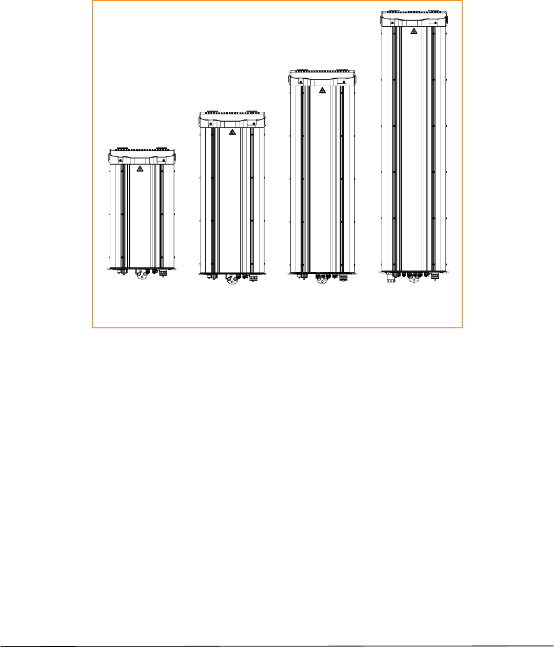
Figure1illustratesthePrismRemoteUnit(PRU),whichcontrolsRFemissions,interfaceswiththeFlexWave
PrismHostUnit.
Single-Bay
Prism Remote Unit
Dual-Bay
Prism Remote Unit
Tri-Bay
Prism Remote Unit
Quad-Bay
Prism Remote Unit
Figure1.PrismRemoteUnits(PRUs)
ThePRUhasfromonetofourRFModulebays,dependingonthePRUmodel.Thatis,theSingle‐BayPRUhasone
RFModulebay,andtheQuad‐BayPRUhasfourRFModulebays.APRUcansupportuptofourRFModules.
ThefunctionofthePRURFModulesontheForwardPathisto:
•convertthedigitizedRFtransportedfromtheHosttoAnalogRF
•amplifytheAnalogRFsignal
•providesignalfiltering.
ThefunctionofthePRURFModulesontheReversePathisto:
•converttheAnalogRFfromthehandsettoDigitalRFfortransporttotheHost
•providesignalfiltering.
NOTE: TheRFModulesarefieldreplaceable,butcannotbeservicedinthefield.

FlexWavePrismRemoteUnitRFModuleInstallationGuide Page7
TECP‐77‐141Issue6•300001744178RevF•July2014 ©2014TEConnectivity
RFModuleDARTs
EachRFModulecansupportanyofthefollowingDARTcombinations:
•oneClassicDARToroneSingleSuperDART
•twoClassicDARTs(i.e.,the6.5W800/900ESMRModule,Non‐Diversity,Classic)
•twoClassicDARTs—Diversity
•twoSingleSuperDARTs—Diversity
•oneDualSuperDART
•oneortwosetsofTxorRxBoards(HDM).
EachRFModulewillhaveuptotwo6‐timeslotDARTsorone12‐timeslotDARTperRFModule.
TheDARTtypedeterminesthemaximumnumberoflinks,wheretherecanbeuptoeightClassicDARTsorSingle
SuperDARTsthatsupport39MHzeach,orupto4DualSuperDARTsthatsupportupto75MHzeach.
PrismsupportstheDARTModuletypeslistedbelow.
•ClassicDARTsare6‐timeslotDARTsthatsupportupto35MHzcontiguousbandwidth(seeTable4on
page7).
•SingleSuperDARTsare6‐timeslotDARTsthatsupporttwonon‐contiguousbandsintheentirefrequency
rangeoftheDART,butcannotexceed39MHztotalRFbandwidth(seeTable5onpage7).
•DualSuperDARTsare12‐timeslotDARTsthatsupportupto60‐75MHz(seeTable6onpage8)
Table4.Single‐BayClassicDARTs
DARTModuleType MaximumBandwidth(MHz) NumberofFiberSlots
800APACiDENClassic 19 3
800SMRClassic 18 3
850CellClassic 25 4
900SMRClassic 5 1
Table5.Single‐BaySuperDARTs(1)
DARTName Usedin… Maximum
Frequency
Span(MHz)
Maximum
Bandwidth
(MHz)
Maximum
Fiber
Slots
HostUnits HEUs
1800GSMSGLSuperDART Yes No 75 39 6
1900PCSSGLSuperDART Yes Yes 70 39 6
2100AWSSGLSuperDART Yes Yes 45 39 6
2100UMTSSGLSuperDART Yes No 60 39 6
700IABCSGLSuperDART Yes Yes 18 18 3
700uCSGLSuperDART Yes Yes 10 10 2
900EGSMSGLSuperDART Yes No 35 35 6
(1) WhenusingaHostUnitwithboththeSeRFIIandSystemBoardIImodules,thebandwidthsandfiberslotsshownareonly
availableinHostUnitDARTSlots1and3forSingle‐BaySuperDARTs.
NOTE: IndustryCanadaPCS20dBnominalbandwidthislessthan61.5MHz.
NOTE: IndustryCanadaAWS20dBnominalbandwidthislessthan47.2MHz
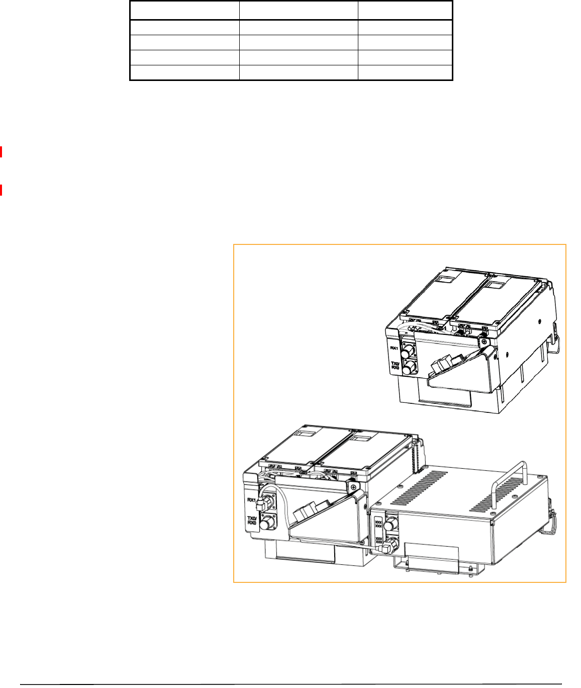
Table6.Dual‐BaySuperDARTs
DARTModuleType MaximumBandwidth(MHz) NumberofFiberSlots
1800GSMDLSuperDART 75 12
1900PCSDLSuperDART 70 12
2100AWSDLSuperDART 45 8
2100UMTSDLSuperDART 60 12
Page8FlexWavePrismRemoteUnitRFModuleInstallationGuide
©2014TEConnectivity TECP‐77‐141Issue6•300001744178RevF•July2014
RFModuleTypes
ThePRURFModulesareavailableinthefollowingformats,andasdescribedinthefollowingsections:
•“Single‐andDual‐BayRFModuleswithClassicorSuperDARTs”onpage8
•“HDMRFModules”onpage9
•“LegacyDual‐Bay40WRFModules”onpage10.
Single‐andDual‐BayRFModuleswithClassicorSuperDARTs
Figure2showsexamplesof
Single‐andDual‐BayRF
Modules,bothofwhichhavetwo
DARTs.
Single‐BayRFModuleshavethe
followingelements:
•oneortwoDARTs
•oneDuplexer
•oneLinearPowerAmplifier
(LPA)
•oneRemoteDARTInterface
(RDI)board.
Dual‐BandDual‐BayRFModules
havethefollowingelements:
•twoDARTs
•twoDuplexers
•oneLinearPowerAmplifier
(LPA)
•oneRemoteDARTInterface
(RDI)board.
Dual-Band Dual-Bay RF Module
Single-Bay Dual-Card RF Module
Figure2.Single‐andDual‐BayRFModules
FlexWavePrismRemoteUnitRFModuleInstallationGuide Page9
TECP‐77‐141Issue6•300001744178RevF•July2014 ©2014TEConnectivity
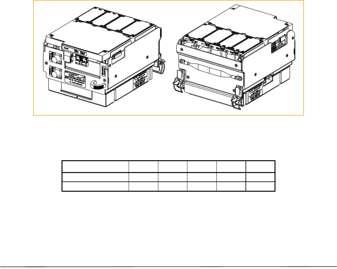
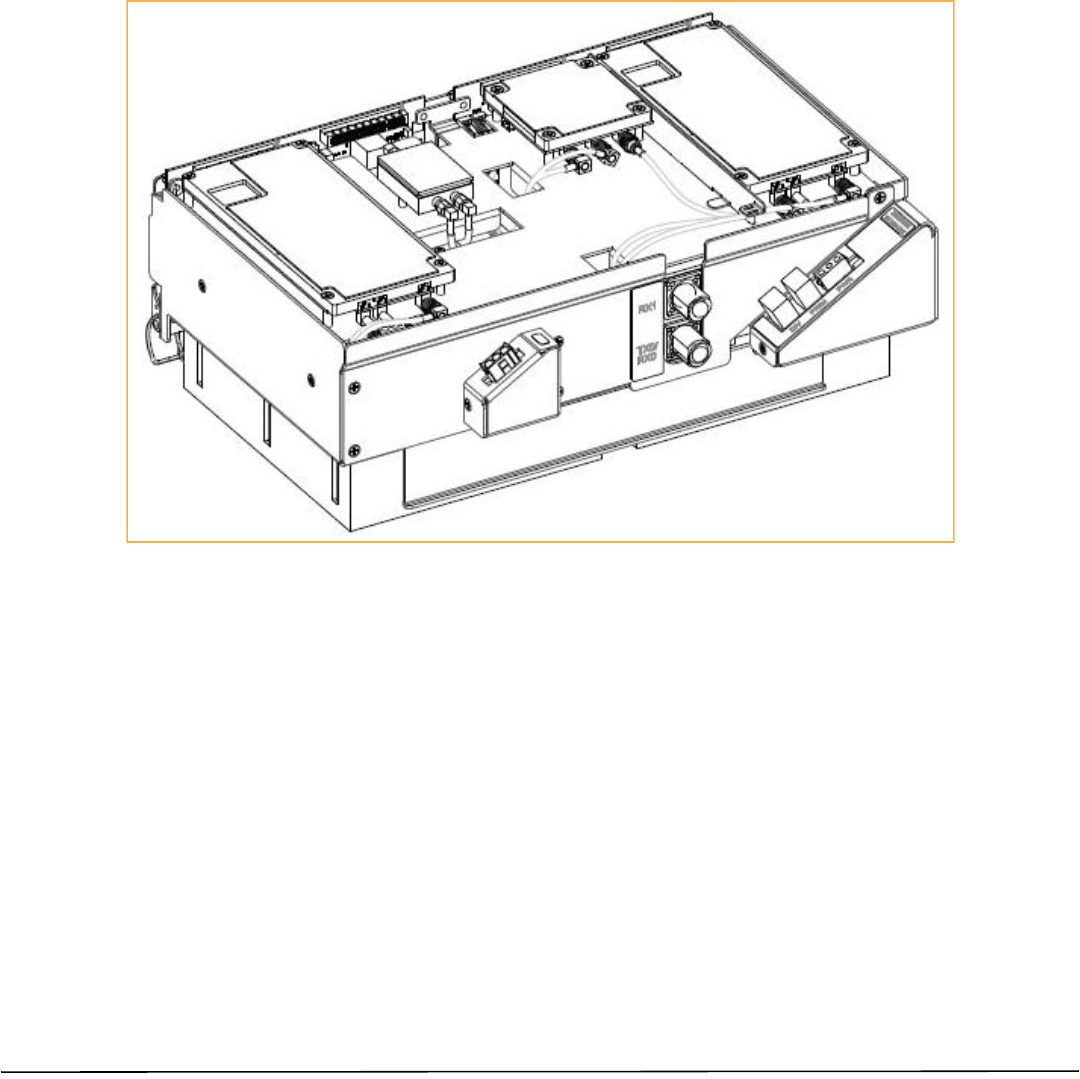
HDMRFModules
HDMRFModules(Figure3)aredesignedtoprovidetheabilitytodeployeithera20WDual/MultipleInput
multipleOutput(MIMO)RFModule(wheredualequalstwobands)ora40WSingleInputSingleOutput(SISO)
RFModulewithinasingle‐bayofaPRU.AnHDMRFModuledoesthefollowing:
•interfacesoneHostDART‐eitherClassicorSuperDART
•supportstwonon‐contiguousRFslicesupto35MHztotalbandwidthinaDualorMIMOconfiguration
•supportsfullbandwidthinaSISOconfiguration,upto75MHz
•supports20Wperband/PathinaDual/MIMORFModule
•supportsupto40WRFoutputpowerinaSISORFModule.
AnHDMRFModulehasthefollowingcomponents:
•oneDPM
•oneortwosetsofTX/RXboards
•oneortwoDuplexers
•oneortwoPowerAmplifiers(PAs).
Figure3.HDMRFModules
ThecomponentsofaPRUHDMRFModulearedependentonthemoduletype,aslistedinTable7.
Table7.ComponentsofPRUHDMRFModules
RFModuleType DPM LPA Duplexer RxCard TxCard
SISO 11111
MIMO/DualBandModule 12222
Page10 FlexWavePrismRemoteUnitRFModuleInstallationGuide
©2014TEConnectivity TECP‐77‐141Issue6•300001744178RevF•July2014
LegacyDual‐Bay40WRFModules
TheLegacyDual‐Bay40WRFModule(Figure5)isdesignedforAWSandPCSfrequenciesandissupportedonly
byClassicDARTs.TheLegacyDual‐Bay40WRFModulecomprises:
•oneClassicDART
•oneDuplexer
•twoPowerAmplifiers(PAs)
•oneRemoteDARTInterface(RDI)board.
NOTE: ThismanualdescribeshowtoinstallthePCS1900andAWS2100Non‐DiversityRFModules.
Figure4.LegacyDual‐Bay40WRFModule
FlexWavePrismRemoteUnitRFModuleInstallationGuide Page11
TECP‐77‐141Issue6•300001744178RevF•July2014 ©2014TEConnectivity
RFMODULECOMPONENTS
Figure5showstypicalRFModulecomponents,usingtheSingle‐BayRFModuleasanexample.
Mounting
latch
Mounting hook Duplexer Power Amplifier (PA)
DARTs
NOTE: The RDI is internal to the RF Module and is therefore not shown.
LNA
(inside the Duplexer cavitiy)
Figure5.Single‐BayRFModuleComponents
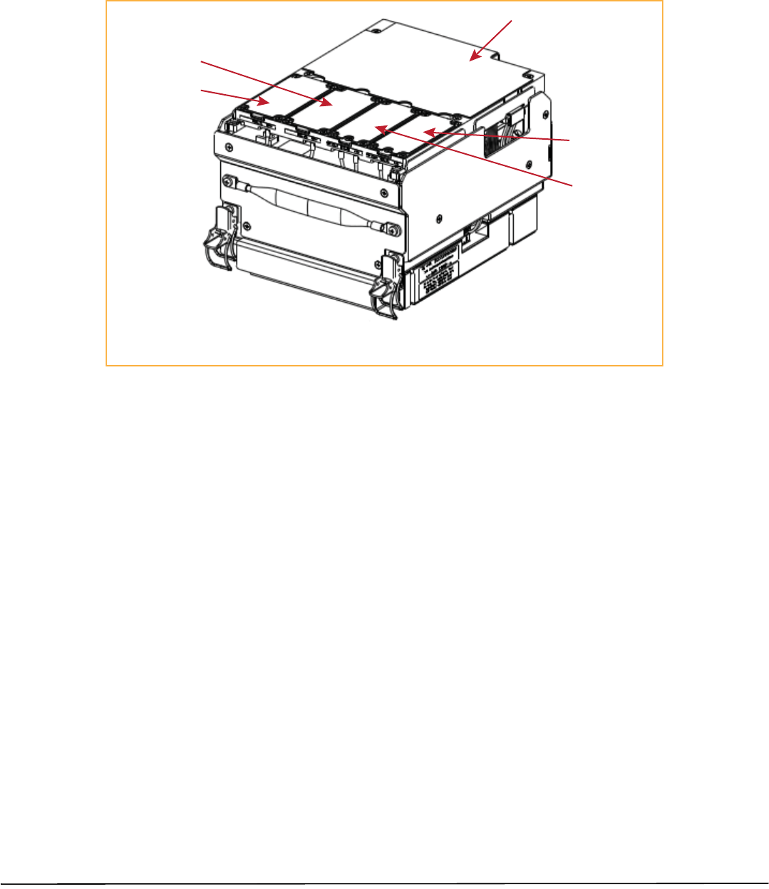
Figure6showsthecomponentsofanHDMRFModule.
Duplexers Power Amplifier
Mounting latch
Mounting hook
Tx and Rx Cards
DPM
Figure6.HDMRFModuleComponents
Page12 FlexWavePrismRemoteUnitRFModuleInstallationGuide
©2014TEConnectivity TECP‐77‐141Issue6•300001744178RevF•July2014
LinearPowerAmplifiers
TheLinearPowerAmplifier(LPA)isahighqualitybroadbandRFamplifierusedforachievingPrism
product‐ratedpowerforthePRUTxforwardpathRF.ThePAsarepass‐bandspecific,withthemaximum
compositeTxpowerlevelslistedinTable8forSingle‐Card,Dual‐Card,andHDMRFModulesandTable9on
page12forLegacyDual‐Bay40WRFModules.
TheLPAishousedwithintheRFModule,andisnotfieldserviceable.
Table8.LPAMaximumCompositeTxPowerLevelsforSingle‐Card,Dual‐Card,andHDMRFModules
Bandwidth(MHz)supportedacrossentirespectrum
Passband Maximum
dBm Watts
HDM
SingleSuperDART Classic
DART
Dual
SuperDART
Dual/MIMO SISO
AWS2100 43 20 39 45 39 NA 45
Cellular850 43 20 25 25 NA 25 NA
46 40 25 25 NA 25 NA
EGSM900 40 10 35 35 35 NA NA
DCS180042 15.8 39 75 39 NA 75
LTE700LowerABC43 20 18 18 18 NA NA
46 40 18 18 18 NA NA
LTE700UpperC43 20 10 10 10 NA NA
46 40 10 10 10 NA NA
PCS1900 43 20 39 70 39 NA 70
PGSM900 40 10 25 25 25 NA NA
SMR800 43 20 7 7 NA 7NA
SMR900 38 6.5 5 5 NA 5NA
UMTS2100 42 15.8 39 60 39 NA 60
Table9.LPAMaximumCompositeTxPowerLevelsforLegacyDual‐Bay40WRFModules
Passband Maximum
dBm Watts
Bandwidth(MHz)
supportedacross
entirespectrum
ClassicDART
PCS1900 +46 40 35
AWS2100 +46 40 35
NOTE: IndustryCanada20dBPassBandModelNumberFWP‐C4MT000MODCellular850MHz=26.3MHzand
thePCS1900=66.8MHz.

FlexWavePrismRemoteUnitRFModuleInstallationGuide Page13
TECP‐77‐141Issue6•300001744178RevF•July2014 ©2014TEConnectivity
DuplexerandLowNoiseAmplifier
TheRFModuleprovidesthePRUwithaninternalDuplexerthatisoptimizedtoprovidethedesiredRFband‐pass
filteringandin‐bandequipmentisolationbetweenFWDandREVpaths.TheDuplexerprovidesthefiltering
necessarytothetransmitandreceivepathstoandfromtheconnectedantenna.
TheDuplexerfortheSingle‐andDual‐BayRFModulesandtheLegacyDual‐Bay40WRFModulescontainsupto
twoREVpathLowNoiseAmplifiers(LNAforPRIand/orSECreversepaths).
TheDuplexerforanHDMRFModuledoesnothaveaLowNoiseAmplifier.
Duplexersarenotfieldserviceable.
DigitalProcessingModule
TheDigitalProcessingModule(DPM)isfoundonlyintheHDMRFModules.TheDPMprovidestheprimary
processingandlogicfunctionsfortheHDMRFModule.ItalsoprovidestheprimarypowerinterfacefortheHDM
RFModule,andconversionofthenative28Vdcvoltagetolowervoltagesasnecessaryforfunctionality.
TheDPMhasaTransmit(Tx)BoardandaReceive(Rx)Board:
•TxBoard—providesbandspecificfilteringfortheintendedTransmitpath.
•RxBoard—providesbandspecificfilteringfortheintendedReceivepath.

Page14 FlexWavePrismRemoteUnitRFModuleInstallationGuide
©2014TEConnectivity TECP‐77‐141Issue6•300001744178RevF•July2014
UNDERSTANDINGTHERFMODULECABLES
BeforeyouinstalltheRFModulecables,familiarizeyourselfwiththerulesthatpertaintothesecables,asdefined
inthefollowingsections.
AlwaysprovidedateachRFModuleshelfarefivecables:
•twoHigh‐SpeedDataCables,whichinthisdocumentarereferredtoasLVDS(Low‐VoltageDifferential
Signaling)cables
•twoRFCables(TX0/RX0)and(TX1/RX1)
•onePower(PWR)Cable.
PowerCableConnection
Maintainadequatestrainreliefdistancesfromtheconnectionpointstothemodule.
LVDSCableConnections
•LVDScableslabeledPRIMandDIVshouldalwayseitherbeconnectedtoaRFModuleorstrainrelievedto
adjacentcables,asthisprotectsthecableagainstdamagethroughmisplacement.
•AlignandfullyinserttheLVDScableconnectorsintotheirrespectiveconnectorcages.Fullinsertionis
identifiedbyanaudibleclick.
•EnsurethetwoLVDScablesarefullyseatedandlatchedintotheirrespectivereceptaclesontheRFModule
bylightlypullingoutwardontheconnectors.Iffullyseatedandlockedintoposition,thecableconnectorswill
notslidebackout.
•Maintainadequatestrain‐reliefdistancesfromtheconnectionpointstotheRFModule.
RFCableConnections
TheRFModulecablesthatarepre‐installedinthePRUconnecttothecorrespondingconnectorsontheRF
Module.TheRFModulecablescorrelatetotheantennaconnectorsonthebottomofthePRUchassis.
RFCableRules
•WheninstallingaDiversity,MIMOorDual‐BandRFModule,bothRFcableslabeledMODNTX0/RX0and
MODNTX1/RX1shallbeconnectedtotheN‐StyleconnectionsoftheRFModule”
NOTE: Olderlabelingschemesused“PRI”and“DIV”.Tomatcholdlabelingschemestocurrentlabeling:
•TX0/RX0=PRI
•TX1/RX1=DIV
•WheninstallingaNon‐DiversityorSISORFModule,oranSMR800/900Dual‐BandDual‐BayRFModule:
–TheMODNTX0/RX0cableshallbeconnectedtothesingleavailableN‐StyleRFConnectionoftheRF
Module.
–TheMODNTX1/RX1cableshallbeconstrainedtotheexistingcablesusingatiewraporsimilarly
acceptedfastenersoitcannotbepinchedorpreventthePRUdoorfromclosing.Donotcutorattemptto
otherwiseremovethisRFCable.

FlexWavePrismRemoteUnitRFModuleInstallationGuide Page15
TECP‐77‐141Issue6•300001744178RevF•July2014 ©2014TEConnectivity
•RFcablesarehand‐formable;however,cablesmustadheretoaminimumbendradiusof1‐inchfromthe
outletoftheintegratedcableguidetotherespectiveN‐StyleRFconnectionontheRFModule.
RFModuleCablesforSingle‐Card,Dual‐Card,andHDMRFModules
TheRFcableandconnectorlabelsalsocorrespondtotheRFModulebaysinthePRUchassis,whereMODAisthe
bottombayandMODDisthetopbay.Intheinstallationsteps,theRFcablesandconnectorsarereferredtoas
MODNTX0/RX0andasMODNTX1/RX1whereNequalsA,B,C,orD.
ThecablesandconnectorshavecorrespondinglabelsasshowninTable10forSingle‐Card,Dual‐Card,andHDM
RFModules.
Table10.RFAntennaLabelsforSingle‐Card,Dual‐Card,andHDMRFModules(FromTopofPRUChassisDown)
RFModule
Cable,RF
Module
Connector,and
RemoteAntenna
ConnectorLabel
Function Single‐Bay
RemoteUnit
RFModule
Bay
Designations
Dual‐BandDual‐BayRemoteUnitRF
ModuleBayDesignations
Dual‐Bay Tri‐Bay Quad‐Bay
BayDModDTX0/RX0 TransmitRFpowerandprimary/Path1receive
to/fromtheantennaforRFModuleDMODDN/A N/A
MODC
ModDTX1/RX1 Diversityreceive/Path2forRFpowerfromthe
antennaforRFModuleD
BayCModCTX0/RX0TransmitRFpowerandprimary/Path1receive
to/fromtheantennaforRFModuleCMODCN/A MODC
ModCTX1/RX1 Diversityreceive/Path2forRFpowerfromthe
antennaforRFModuleC
BayBModBTX0/RX0TransmitRFpowerandprimary/Path1receive
to/fromtheantennaforRFModuleBMODB
MODAMODAMODA
ModBTX1/RX1 Diversityreceive/Path2forRFpowerfromthe
antennaforRFModuleB
BayAModATX0/RX0TransmitRFpowerandprimary/Path1receive
to/fromtheantennaforRFModuleAMODA
ModATX1/RX1 Diversityreceive/Path2forRFpowerfromthe
antennaforRFModuleA

Page16 FlexWavePrismRemoteUnitRFModuleInstallationGuide
©2014TEConnectivity TECP‐77‐141Issue6•300001744178RevF•July2014
RFModuleCablesforDual‐BayInstallations
ForDual‐Bayinstallations,theRFcablesandconnectorsarelabeledasMODNTX0/RX0andMODNTX1/RX1,
whereNreferstothetopbayofthedouble‐bayinstallation.Forexample,foraDual‐Bayinstallationina
Quad‐Baychassis,theRFcablesandconnectorsarelabeledasMODCTX0/RX0andMODCTX1/RX1.
ThecablesandconnectorshavecorrespondinglabelsasshowninTable11onpage16forLegacyDual‐Bay40W
RFModules.
Table11.RFAntennaLabelsforLegacyDual‐Bay40WRFModules(FromTopofPRUChassisDown)
RFModule
Cable,
RFModule
Connector,and
RemoteAntenna
ConnectorLabel
Function 40WDual‐BayRemoteUnitRFModuleBayDesignations
Dual‐Bay Tri‐Bay Tri‐Bay Quad‐Bay
BayDModDTX0/RX0 TransmitRFpowerand
primary/Path1receiveto/from
theantennaforRFModuleDN/A N/A N/A
MODC
MODD
MODC
ModDTX1/RX1 Diversityreceive/Path2forRF
powerfromtheantennaforRF
ModuleD
BayCModCTX0/RX0TransmitRFpowerand
primary/Path1receiveto/from
theantennaforRFModuleCN/A MODC
MODC
MODC
ModCTX1/RX1 Diversityreceive/Path2forRF
powerfromtheantennaforRF
ModuleC
BayBModBTX0/RX0TransmitRFpowerand
primary/Path1receiveto/from
theantennaforRFModuleB
MODBMODBMODBMODB
MODB
ModBTX1/RX1 Diversityreceive/Path2forRF
powerfromtheantennaforRF
ModuleB
BayAModATX0/RX0TransmitRFpowerand
primary/Path1receiveto/from
theantennaforRFModuleAMODAMODA
ModATX1/RX1 Diversityreceive/Path2forRF
powerfromtheantennaforRF
ModuleA
Note: ForDualModuleinstallationsthecentermoduleshelfneedstoberemoved;see“Dual‐BayModulesOnly—RemovetheModuleBay
Shelf”onpage24.
Note: InstalltheLegacyDual‐Bay40WRFModuleinthelower‐mostbayinthechassis.If,however,iftwoLegacyDual‐Bay40WRFModules
arepresent,installthe2100Moduleinthelower‐mostBayandthe1900Moduleintheupper‐mostBay.
FlexWavePrismRemoteUnitRFModuleInstallationGuide Page17
TECP‐77‐141Issue6•300001744178RevF•July2014 ©2014TEConnectivity
RFGroupAssignmentsforPRUs
APRUcomprisesfromonetofourRFModulebays.Figure7illustratesthenumberingofRFModulebaysand
DARTs.
Quad-Bay Remote Unit with Single-Card RF Modules
SeRF Module
DART 7
DART 8
Bay D
DART 5
DART 6
Bay C
DART 3
DART 4
Bay B
DART 1
DART 2
Bay A
Figure7.RFModulesBaysinaPRU

Page18 FlexWavePrismRemoteUnitRFModuleInstallationGuide
©2014TEConnectivity TECP‐77‐141Issue6•300001744178RevF•July2014
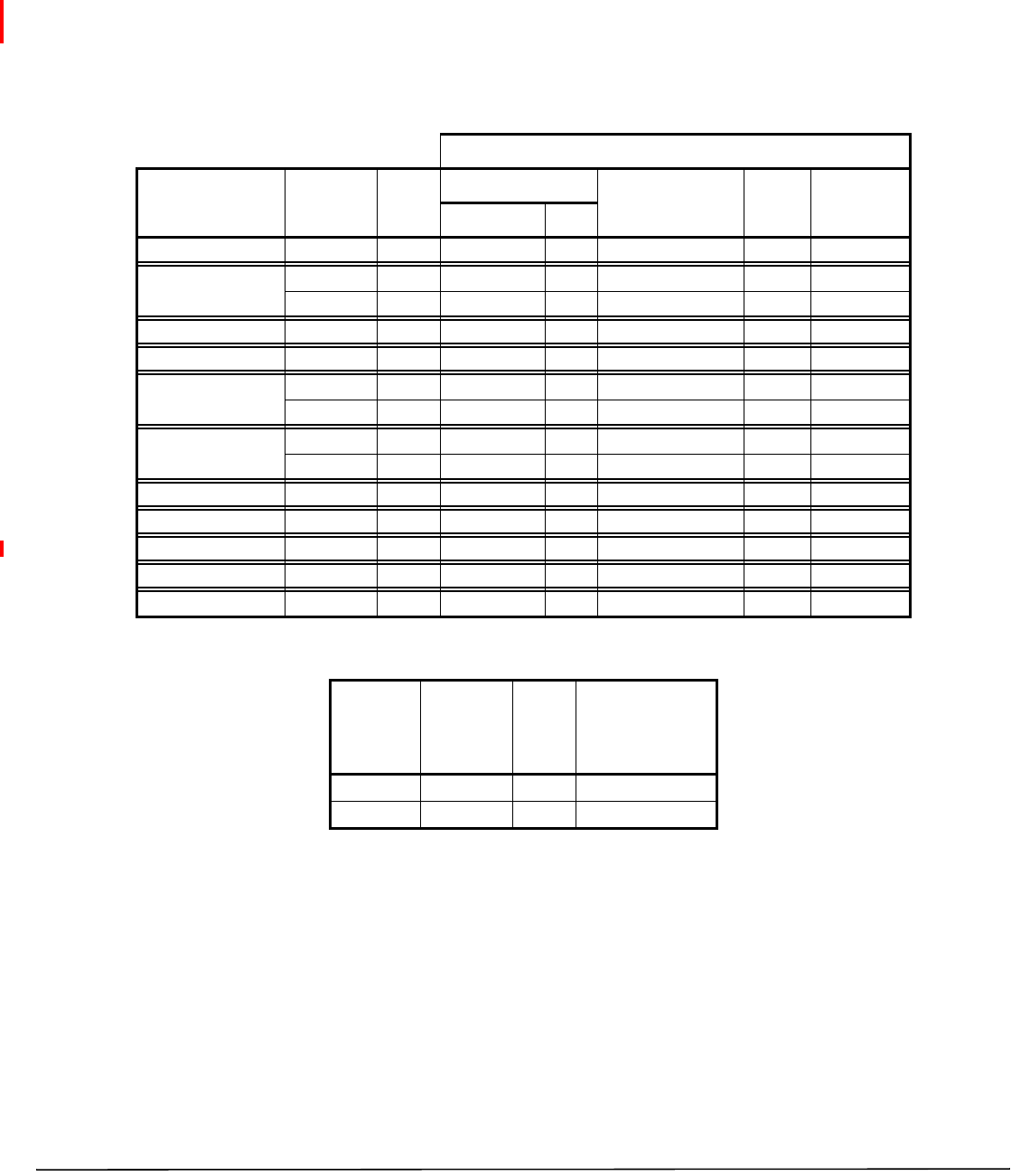
Table12listshowtheFlexWavePrismEMSreferencestheRFgroupassignmentsandcorresponding
componentsofeachRFModule.
Table12.RemoteUnitRFGroupAssignments(fromTop/Down)
PhysicalRF
Bay
DART
Number
LNANumber LPA
Number
forSingle
LPA
LPA
Numberfor
DualLPAs
Power
Detector
Numberfor
SinglePD
Power
Detector
Numberfor
DualPDs
Primary Diversity
D8 8 7878
7 7 7 7
C6 6 5656
5 5 5 5
B4 4 3434
3 3 3 3
A2 2 1212
1 1 1 1
NOTE: Forsoftwarereleasespriorto7.3,theLPAswerelabeledas1,2,3,and4.
NOTE: InadualLPAsystem,theConfigureRemoteForwardGainpageshowstwovaluesfortheLPAstatus,one
foreachLPA.ChangingtheLPAModeorresettingtheLPAappliestobothLPAsatthesametime.
CAUTION! ShouldyoursystemexperienceanLPAproblem,refertoTable12toensurethatyouapplynewsettingsor
troubleshootthecorrectRFModule.
CAUTION! IfyouuseacustomizedSNMPpollingforsystemstatus,youmustchangeyourLPAindexingscheme.
FlexWavePrismRemoteUnitRFModuleInstallationGuide Page19
TECP‐77‐141Issue6•300001744178RevF•July2014 ©2014TEConnectivity
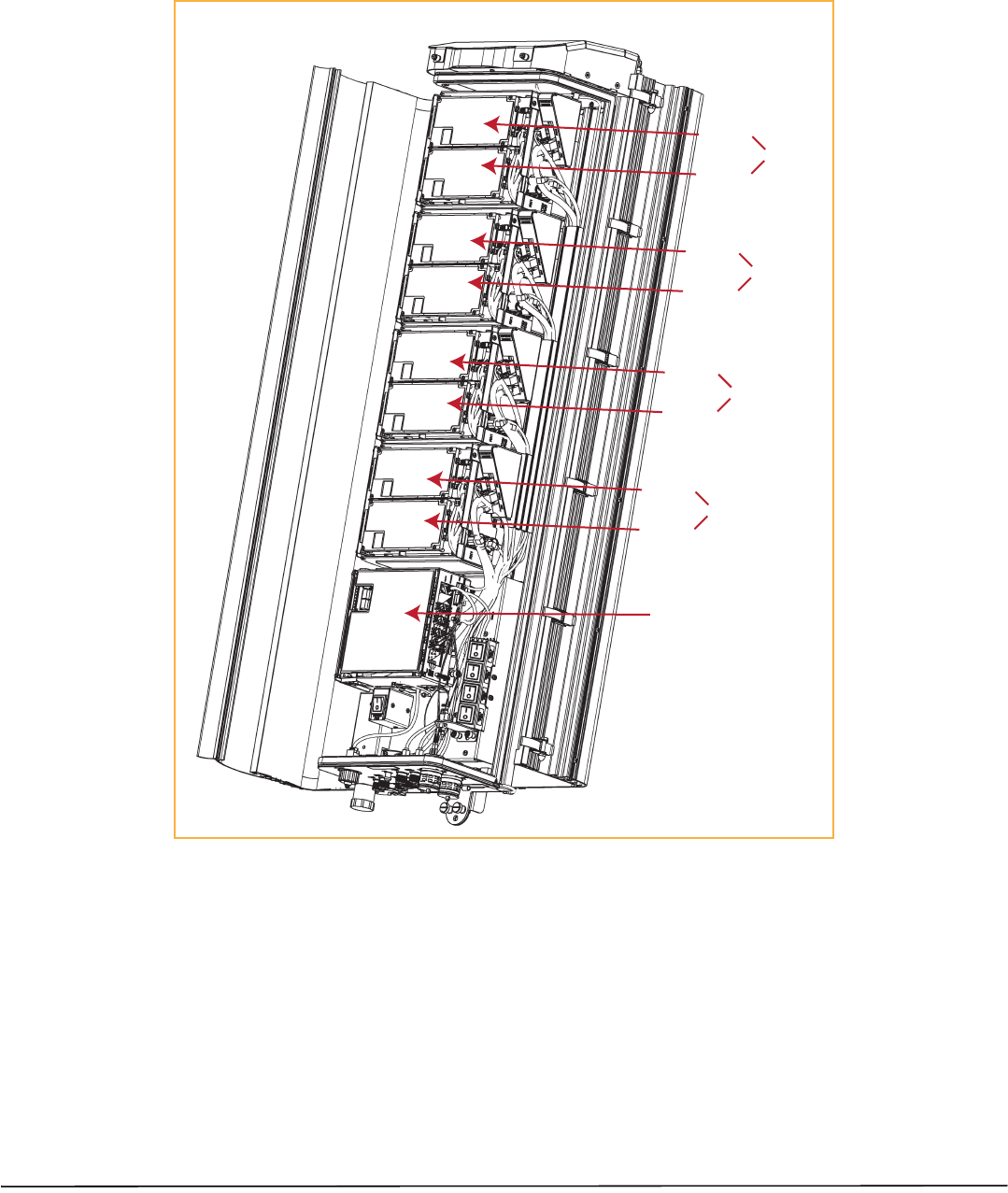
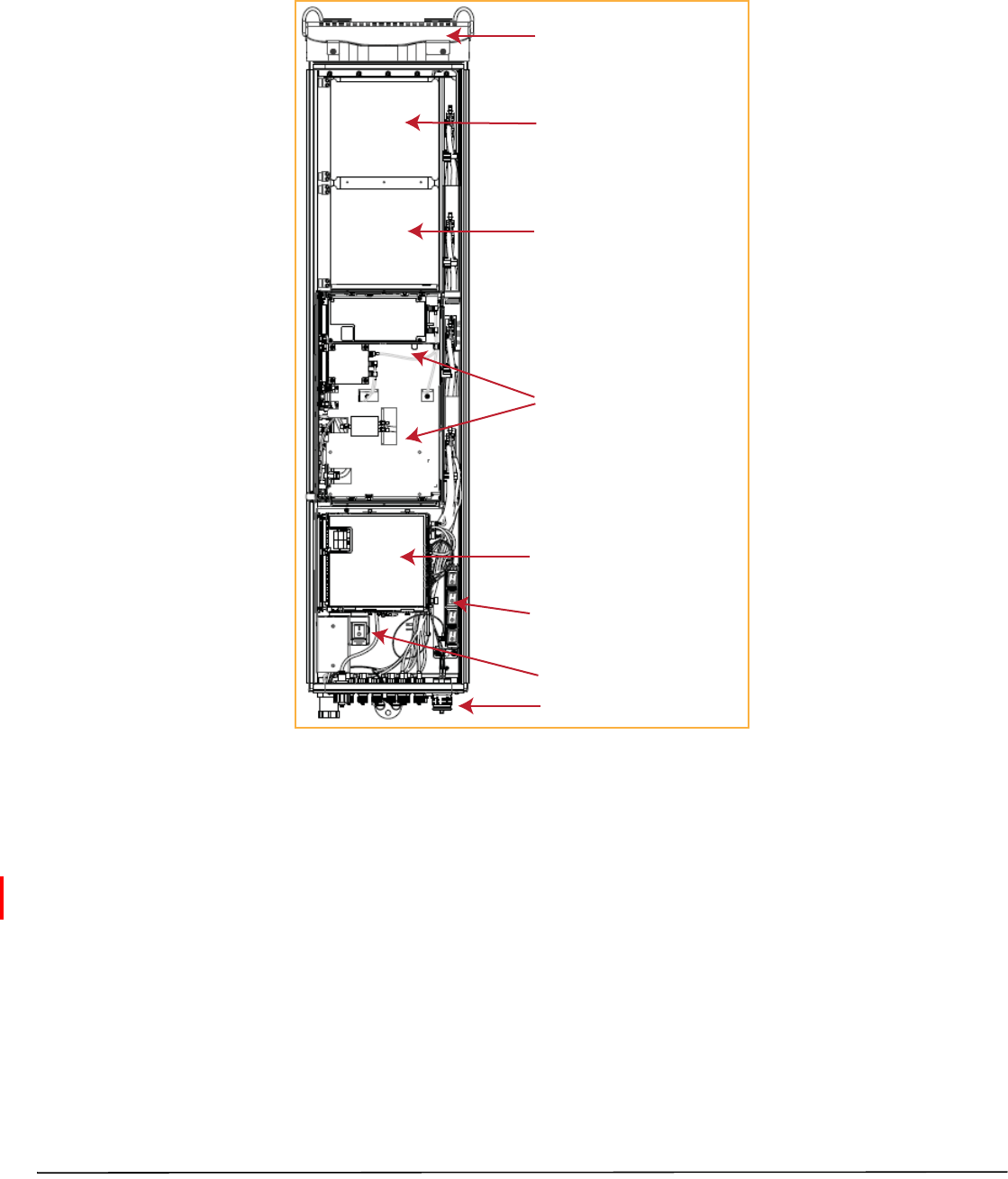
TheLegacyDual‐Bay40WRFModuleoccupiestwobaysinaPRU.Figure8showsthemaincomponentsinaPRU
enclosure,withaLegacy40WRFModuleoccupyingBaysAandB.ThecontrollingDARTwillalwaysbeinthe
upperbay(BorD),andthesecondLPAisalwaysinthelowerbay(AorC).
Legacy Dual-Bay 40W RF Module
in Bay B (upper slot) and
Bay A (lower slot) with the
controlling DART in Bay B
AC or DC power switch
Four DC power switches
SeRF Module and Power supplies
Bay C (empty for future use)
Bay D (empty for future use)
Fans
Connectivity panel with Status LED
Figure8.LegacyDual‐Bay40WRFModuleinaQuad‐BayPRU
NOTE: IfaLegacyDual‐Bay40WRFModuleAWS2100andaLegacyDual‐Bay40WRFModulePCS1900are
bothinstalledinaQuad‐BayPRU,itisrecommendedthatthePCS1900beinstalledinupper‐mostbay,
andtheAWS2100beinstalledinthelower‐mostbay.
NOTE: Toaccommodatetwo‐baymodules,youneedtoremoveamodulebayshelfasdescribedin“Dual‐Bay
ModulesOnly—RemovetheModuleBayShelf”onpage24.

Page20 FlexWavePrismRemoteUnitRFModuleInstallationGuide
©2014TEConnectivity TECP‐77‐141Issue6•300001744178RevF•July2014
INSTALLTHERFMODULE(S)
ThefollowingsectionsguideyouthroughtheinstallationofanRFModuleintoaPRUchassis.Theprocessto
installthefourdifferenttypesofRFModulesisbasicallythesame;however,differencesarenotedandshouldbe
followed.
NOTE: Inthefollowingsteps,theRFcablesandconnectorsarereferredtoasMODNTX0/RX0andasMODN
TX1/RX1whereNequalsA,B,C,orD.
NOTE: WheninstallingRFModules,populatetheRFModulesfromhighestfrequencybandtolowestwithinthe
PRU.Likewiseforpoweroutput,populatefromthebottombaytothetop;higheroutputtolower
output.Thatis,foradeploymentwith210040W,190040W,85020Wand70020WMIMO,installthe
RFModulesasfollows:
•210040WRFModuleinBayA
•190040WRFModuleinBayB
•85020WRFModuleinBayC
•70020WMIMORFModuleinBayD.
SafetyPrecautions
CAUTION! Thisisrestrictedaccessequipmentandonlyqualifiedservicepersonnelshouldserviceandoperatethisequipment
usingappropriatetools.
CAUTION! Wetconditionsincreasethepotentialforreceivinganelectricalshockwheninstallingorusing
electrically‐poweredequipment.Topreventelectricalshock,neverinstalloruseelectricalequipmentinawet
locationorduringalightningstorm.
CAUTION! Alwaysallowsufficientfiberlengthtopermitroutingofpatchcordsandpigtailswithoutseverebends.Fiberoptic
patchcordsorpigtailsmaybepermanentlydamagedifbentorcurvedtoaradiusoflessthan2inches(5.1cm).
CAUTION! ExteriorsurfacesofthePrismRemoteUnitmaybehot.Usecautionduringservicing.
CAUTION! Servicepersonnelmustconfirmthattheperimetergasketanddoor‐to‐doorgasketsareinplacewhenclosingthe
Prismdoorsafterservicing.
CAUTION! ThisequipmentusesaClass1LaseraccordingtoFDA/CDRHrules.Laserradiationcanseriouslydamagetheretina
oftheeye.Donotlookintotheendsofanyopticalfiber.Donotlookdirectlyintotheopticaltransceiverofany
digitalunitorexposuretolaserradiationmayresult.Anopticalpowermetershouldbeusedtoverifyactivefibers.
AprotectivecaporhoodMUSTbeimmediatelyplacedoveranyradiatingtransceiveroropticalfiberconnectorto
avoidthepotentialofdangerousamountsofradiationexposure.Thispracticealsopreventsdirtparticlesfrom
enteringtheadapterorconnector.
CAUTION! ThissystemisanRFTransmitterandcontinuouslyemitsRFenergy.Maintain3foot(91.4cm)minimumclearance
fromtheantennawhilethesystemisoperating.Whereverpossible,shutdowntheRANbeforeservicingthe
antenna.

FlexWavePrismRemoteUnitRFModuleInstallationGuide Page21
TECP‐77‐141Issue6•300001744178RevF•July2014 ©2014TEConnectivity
GuardagainstDamagefromElectro‐StaticDischarge
CAUTION! Electro‐StaticDischarge(ESD)candamageelectroniccomponents.TopreventESDdamage,alwayswearanESD
wriststrapwhenworkingwithaPrismRemoteUnitorwhenhandlinganyofitscomponents—includingtheRF
Modules.ConnectthegroundwireontheESDwriststraptoanearthgroundsourcebeforetouchingthePrism
RemoteUnitoranyofitscomponents.WearthewriststraptheentiretimethatyouworkwiththePrismRemote
Unitanditscomponents.
CAUTION! PlacePrismRFModulesinanti‐staticpackingmaterialwhentransportingorstoringthem.
UnpackandInspecttheRFModule
1Inspecttheexterioroftheshippingcontainer(s)forevidenceofroughhandlingthatmayhavedamagedthe
componentsinthecontainer.
2Unpackeachcontainerwhilecarefullycheckingthecontentsfordamageandverifywiththepackingslip.
3Ifdamageisfoundorpartsaremissing,fileaclaimwiththecommercialcarrierandnotifyTECustomer
Service(see“ContactingTEConnectivity”onpage48).Savethedamagedcartonsforinspectionbythecarrier.
4Saveallshippingcontainersforuseiftheequipmentrequiresshipmentatafuturedate.
CAUTION! HandletheRFModulewithcareduringinstallation.Beespeciallycarefultonotdamagethethermal‐interface
material(TIM),whichisattachedtotheLPA.IftheTIMisdamaged,theLPAcanoverheat.BeforeinstallingtheRF
Module,checktoseeiftheheatsinkmaterialisgougedorcracked.IftheTIMisdamaged,donotinstalltheRF
ModuleandcontactTEConnectivityforassistance(see“ContactingTEConnectivity”onpage48forcontact
information).
CAUTION! Ifthethermal‐interfacematerialisdamaged,theinstallationanduseoftheRFModulemayvoidthewarrantyof
theRFModule.
Page22 FlexWavePrismRemoteUnitRFModuleInstallationGuide
©2014TEConnectivity TECP‐77‐141Issue6•300001744178RevF•July2014
RemoveReleaseLinersfromtheRFModule
NOTE: ReleaseLinersarepresentonfrontandbackofnewmodules.
1OpenthePRUenclosure.
2Removereleaseliners,ifpresent,fromthethermalpadsontheRFModulepriortoinstallingthemoduleinto
thePRUchassis.
CAUTION! Thethermalpadsareverysensitivetomishandling—donotnick,scratch,ordingthem.
ForSingle‐andDual‐BayRFModules,thethermalpadsarelocatedaslistedbelowandasshowninFigure9
onpage22,whichshowsaLegacyDual‐Bay40WRFModule.
•onelargepadonthebacksurfaceofeachLinearPowerAmplifier(LPA)
•uptotwoonthefrontsurface(DARTs)
•oneontheleftsideforthe(RDI)
•oneonthevectormodulatorboard
One large
thermal pad on each PA
(bottom of the LPA)
One thermal pad
for the RDI
One thermal pad
for each DART
One thermal pad
for each DART
One thermal pad
for RF Power
Combiner
One thermal pad
for Vector
Modulator
•oneontheRFpowercombiner.
Figure9.ThermalPadsonaLegacyDual‐Bay40WRFModule
FlexWavePrismRemoteUnitRFModuleInstallationGuide Page23
TECP‐77‐141Issue6•300001744178RevF•July2014 ©2014TEConnectivity
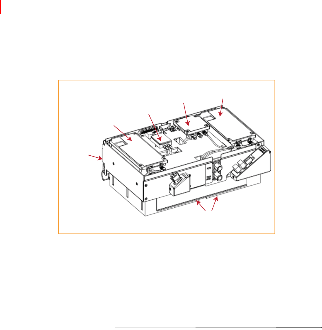
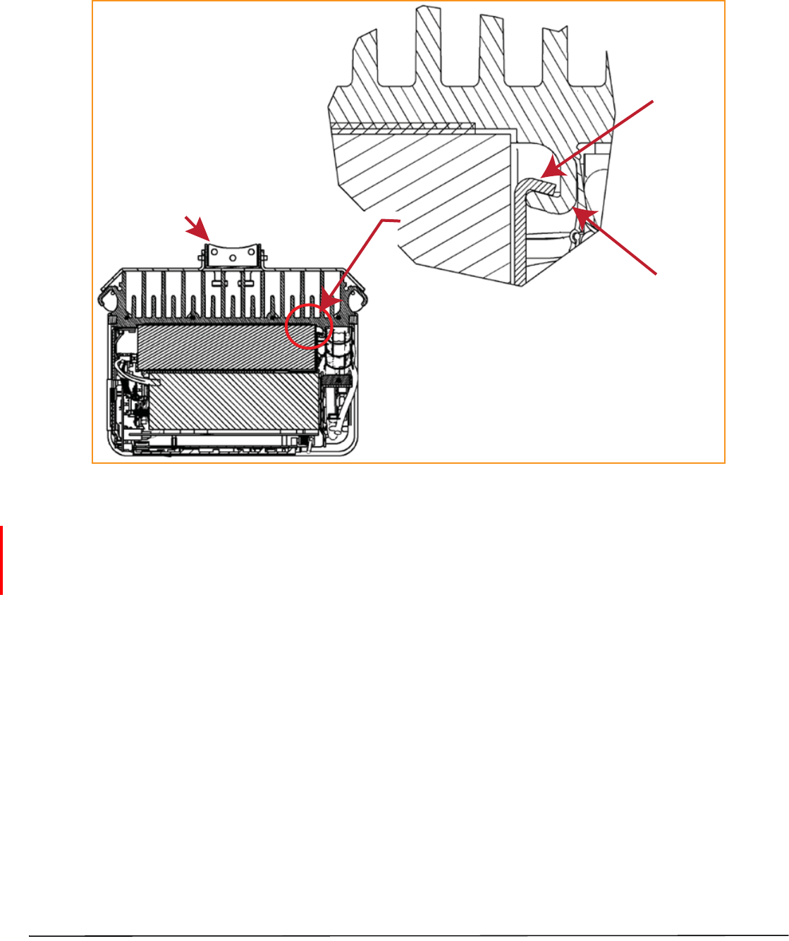
ForHDMRFModules,thethermalpadsarelocatedaslistedbelowandasshowninFigure10.
•onepadforeachRxandTxboard
•onelargepadovertheDPM
•oneforeachPowerAmplifier(PA),whichisonthebottomoftheHDMRFModule.
DPM Thermal Pad
Tx A Thermal Pad
Tx B Thermal Pad
Rx A Thermal Pad
Rx B Thermal Pad
2.9796 in2.9796 in
NOTE: Tx and Rx cards are paired: Tx A ony pairs with Rx A and Tx B only pairs with Rx B.
Figure10.ThermalPadsonanHDMRFModule
Page24 FlexWavePrismRemoteUnitRFModuleInstallationGuide
©2014TEConnectivity TECP‐77‐141Issue6•300001744178RevF•July2014
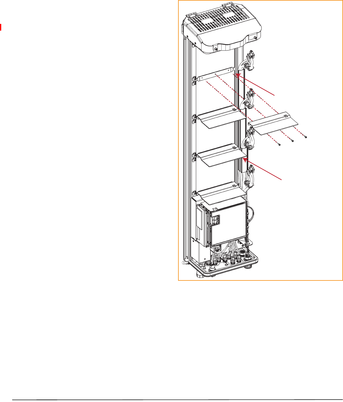
Dual‐BayModulesOnly—RemovetheModuleBayShelf
1FORDUAL‐BAYRFMODULESONLY.
Use 9/64” Allen Wrench to
remove the three module-shelf screws
Remove Module D Shelf for
Dual-Band Dual-Slot RF Modules
Remove Module B Shelf for
Dual-Slot 40W RF Modules
IfyouareinstallingaDual‐BayRFModule,you
mustremoveamodulebayshelffromthePRU
chassistoaccommodatethemodule’ssize.(For
furtherinformation,seeTable10onpage15.)
RemovetheshelfasappropriatefortheRF
Module:
•ForaLegacyDual‐Bay40WRFModule,when
installingintheAandBBays,removethe
ModuleBBayShelf.
•ForaDual‐BayRFModule,wheninstallingin
theCandDBays,removeModuleDBayShelf.
ToremoveaModuleBayShelf:
aUsea9/64”Allen™wrenchtoremovethe
threescrewsthatattachthemoduleshelfto
thePRUchassis,asshowninthefollowing
graphic.
bDiscardorstorethemoduleshelfand
fasteners.
FlexWavePrismRemoteUnitRFModuleInstallationGuide Page25
TECP‐77‐141Issue6•300001744178RevF•July2014 ©2014TEConnectivity
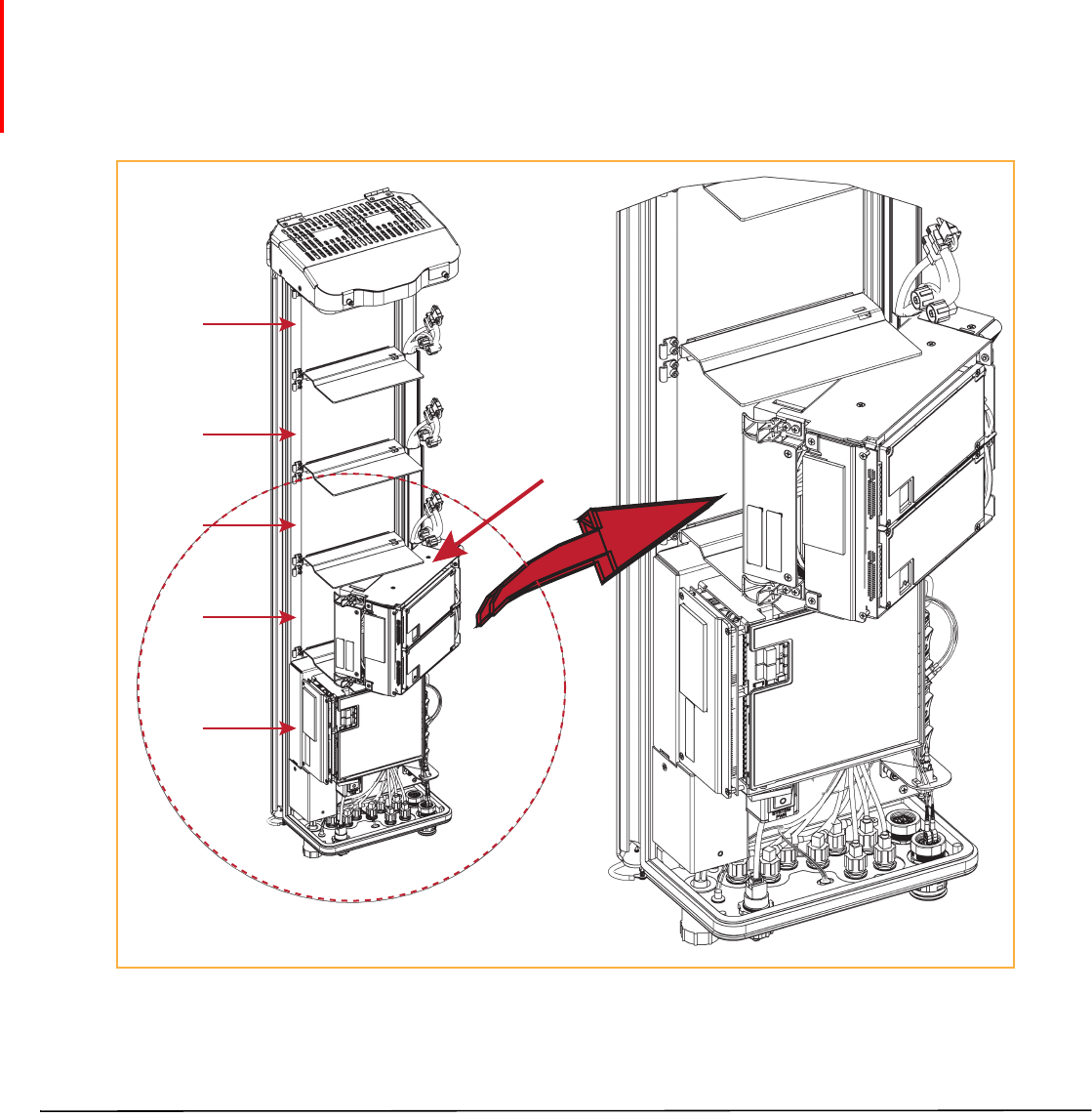
InstalltheRFModuleintothePrismRemoteChassis
1HoldtheRFModulesothattheDARTcard(s)faceawayfromthePRUandtheMountingHookistowardthe
ReceivingflangeonthePRUchassis.
NOTE: AlwaysinstallRFModulesfromthebottomup.Donotskipabay,asthisprovidesmoreefficientheat
dissipation.
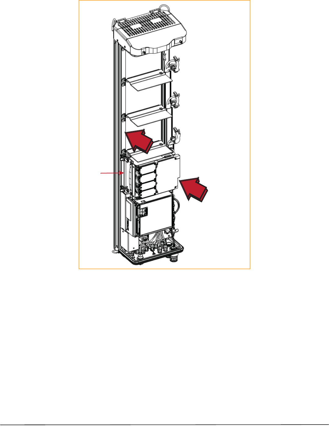
2HoldingtheRFModuleata45°angleinrespecttotherearheatsink,restthebottomsurfaceofthemodule
ontheRFModuleshelf,asshowninoneofthefollowinggraphics,andasapplicabletotheRFModule.
•Single‐BayRFModule:Figure11onpage25
•HDMRFModule:Figure12onpage26
•Dual‐BayRFModule:Figure13onPage27
•LegacyDual‐Bay40WRFModule:Figure14onPage28.
Bay C
Bay D
SeRF
Module
Bay A
Bay B
Single-Slot
RF Module
Heat Sink
Figure11.InstallingaSingle‐BayRFModule
Bay C
Bay D
SeRF Module
Bay A
Bay B
HDM RF Module
Page26 FlexWavePrismRemoteUnitRFModuleInstallationGuide
©2014TEConnectivity TECP‐77‐141Issue6•300001744178RevF•July2014
Figure12.InstallinganHDMRFModule
Installing a Dual-Band
Dual-Slot RF Module
FlexWavePrismRemoteUnitRFModuleInstallationGuide Page27
TECP‐77‐141Issue6•300001744178RevF•July2014 ©2014TEConnectivity
Figure13.InstallingaDual‐BayRFModule
Page28 FlexWavePrismRemoteUnitRFModuleInstallationGuide
©2014TEConnectivity TECP‐77‐141Issue6•300001744178RevF•July2014
Figure14.InstallingaLegacyDual‐Bay40WRFModule
FlexWavePrismRemoteUnitRFModuleInstallationGuide Page29
TECP‐77‐141Issue6•300001744178RevF•July2014 ©2014TEConnectivity
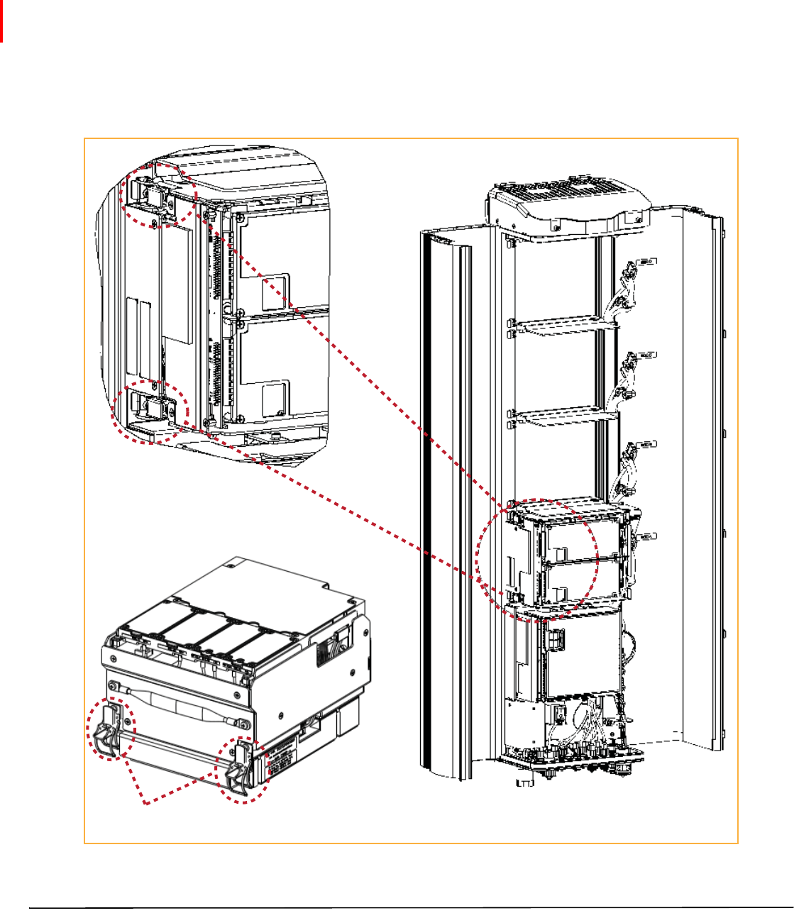
3AligntheMountingHookonthemodulewiththereceivingflangeonthePRUheatsink,andthenslidetheRF
Moduleintowardtheflangeuntilitcangonofurther.
RF Module
Mounting
hook
Chassis
Receiving
flange
Mounting Bracket at
back of the PRU
(View is looking down into the
PRU chassis from the top.)
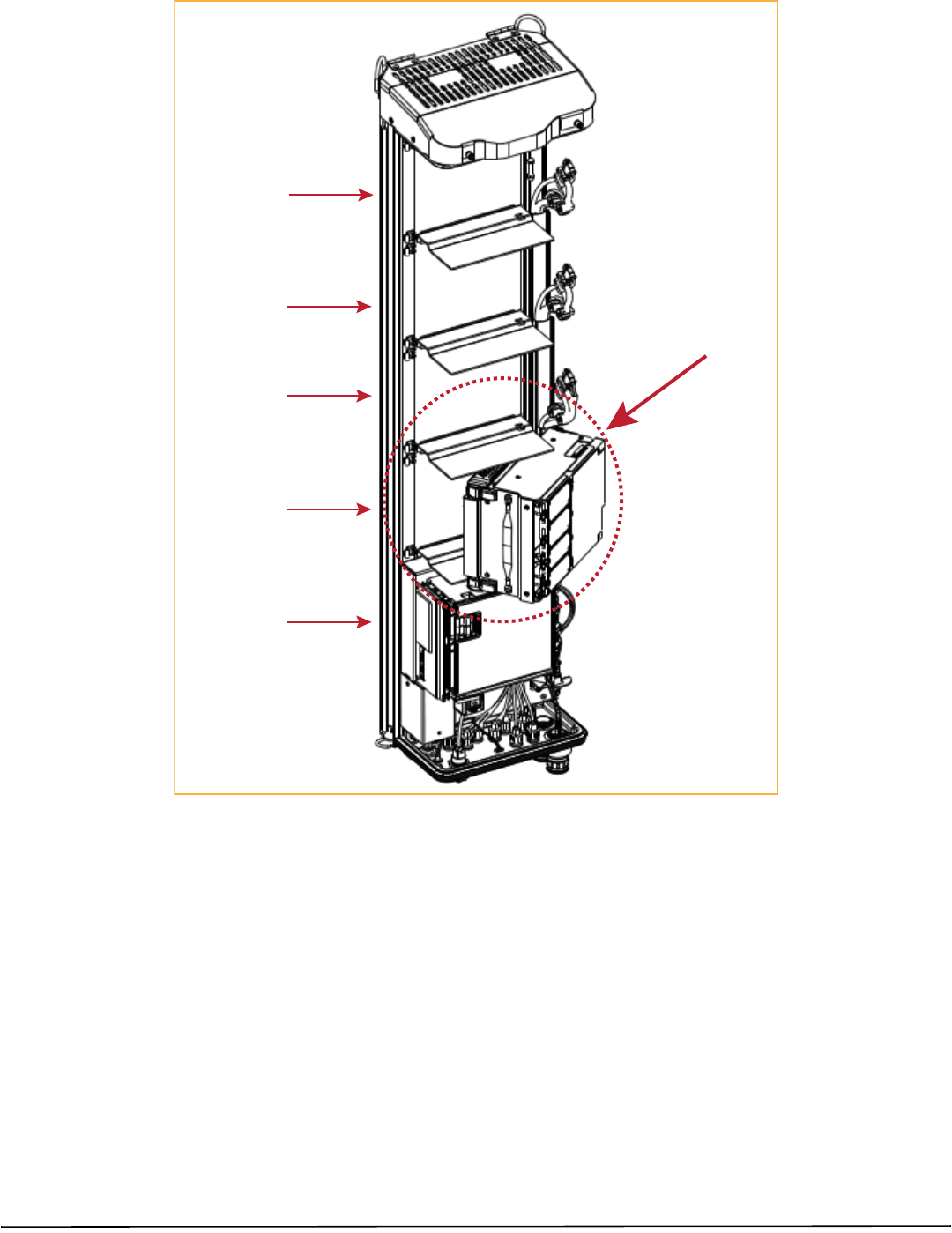
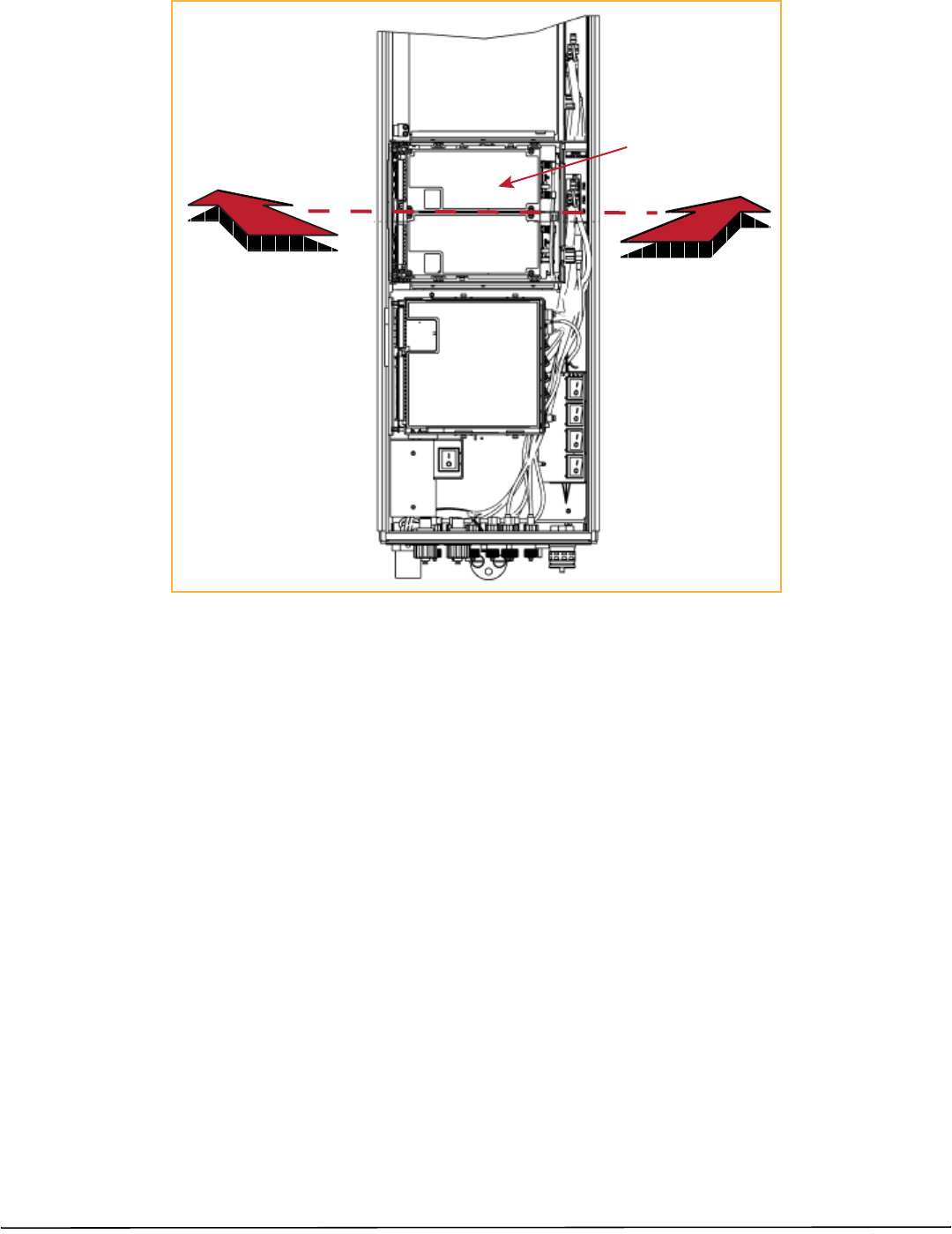
4PushtheleftedgeoftheRFModulebackandintothePRUchassisuntilitcangonofurther,asshowninthe
followinggraphics:
•ForSingle‐BayRFModules,seeFigure15onpage30.
•ForHDMRFModules,seeFigure16onpage31.
•ForDual‐BayRFModules,seeFigure17onpage32,whichusestheLegacyDual‐Bay40WRFModuleas
anexample.
CAUTION! MakesuretheRFModuleisseatedcorrectlyintheModuleshelf.IncorrectalignmentoftheRFModulecancause
theRFModuletofailduetooverheating.
•ThefrontedgeoftheRFModuleshouldbeparallelwiththeshelfaboveit.
•TheMountingHookontheRFModuleshouldbefullyengagedwiththeReceivingflangeonthePRUchassis.
•IfyoulatercannotshutthePRUdoor,verifythattheRFModuleisinstalledcorrectly.
Push the RF Module
back into the chassis
until it can go no further.
Single-Slot
RF Module
Page30 FlexWavePrismRemoteUnitRFModuleInstallationGuide
©2014TEConnectivity TECP‐77‐141Issue6•300001744178RevF•July2014
Figure15.SeatingaSingle‐BayRFModule
Push the HDM RF Module
back into the chassis
until it can go no further.
HDM
RF Module
FlexWavePrismRemoteUnitRFModuleInstallationGuide Page31
TECP‐77‐141Issue6•300001744178RevF•July2014 ©2014TEConnectivity
Figure16.SeatinganHDMRFModule
Push the RF Module back
into the chassis until it can
go no further.
Page32 FlexWavePrismRemoteUnitRFModuleInstallationGuide
©2014TEConnectivity TECP‐77‐141Issue6•300001744178RevF•July2014
Figure17.SeatingaDual‐BayRFModule
FlexWavePrismRemoteUnitRFModuleInstallationGuide Page33
TECP‐77‐141Issue6•300001744178RevF•July2014 ©2014TEConnectivity
SecureRFModuleLatches
1TosecurethemodulelatchesontheleftsideoftheRFModule,dooneofthefollowing,asappropriateforthe
RFModulebeinginstalled:
•“ConnectLatchesonSingle‐BayandHDMRFModules”onpage33
•“ConnectLatchesonDual‐BayRFModules”onpage34.
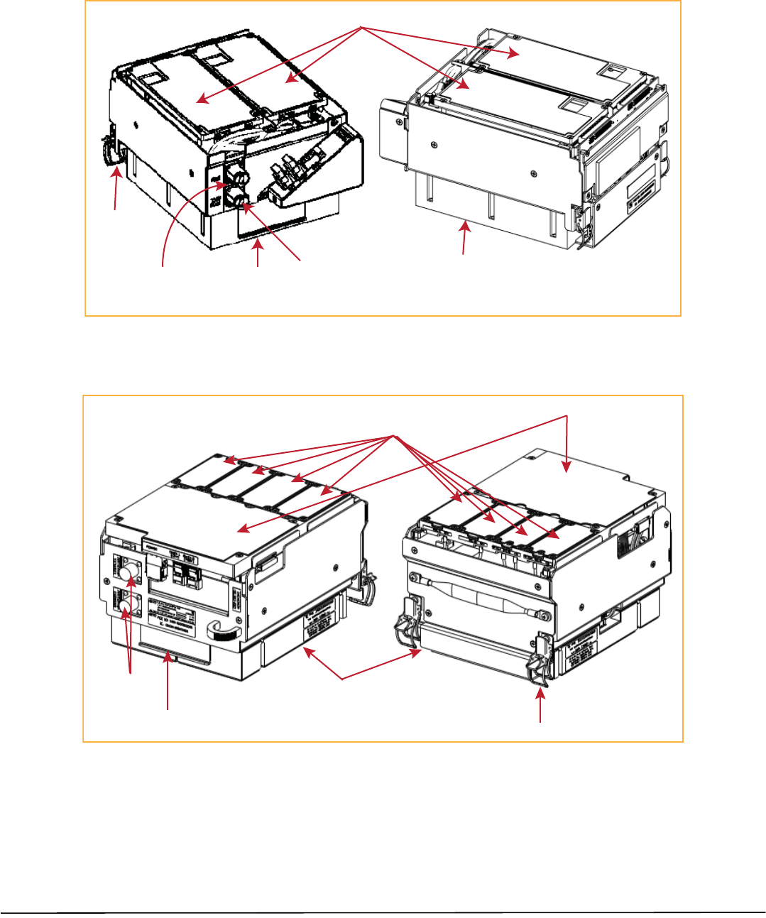
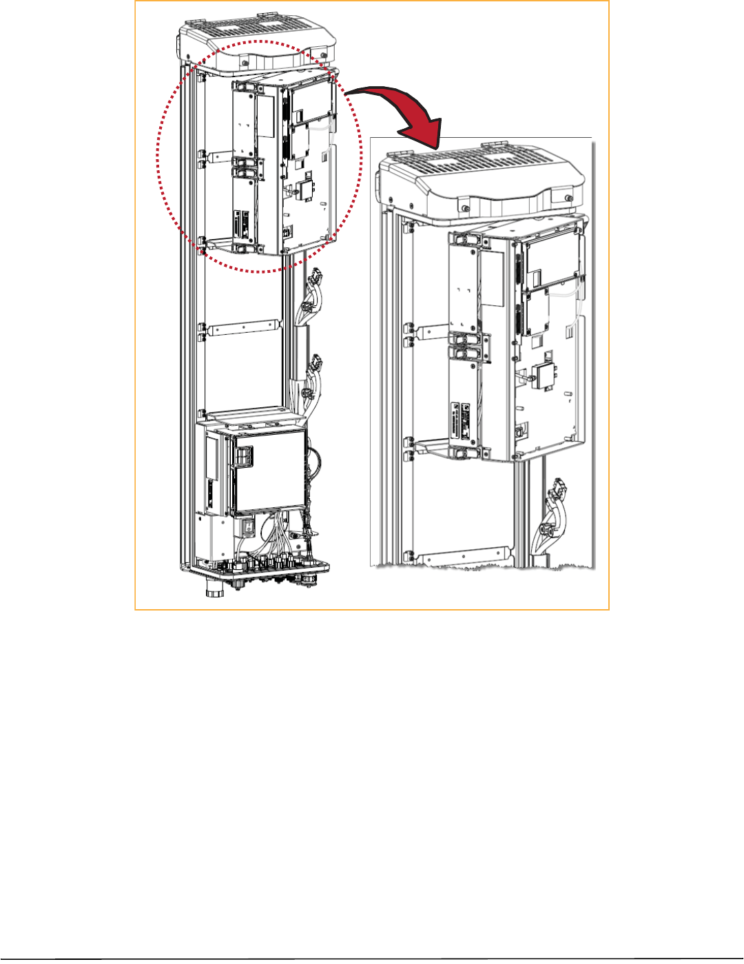
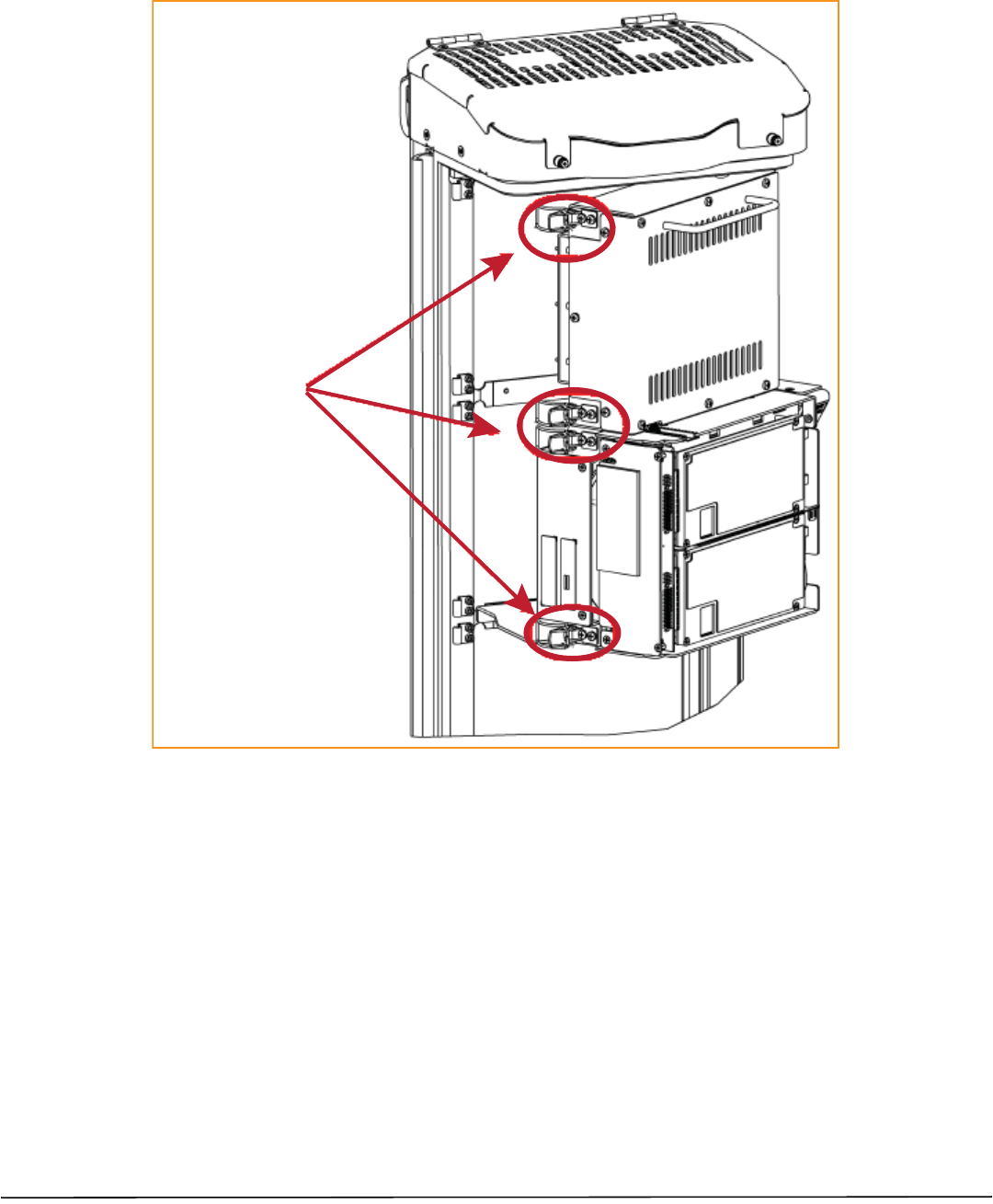
ConnectLatchesonSingle‐BayandHDMRFModules
ForSingle‐BayandHDMRFModules,securetwolatches,asshowninFigure18.
Two latches on Single-Slot
RF Modules
Two latches on
HDM RF Modules
Figure18.LatchesonSingle‐BayandHDMRFModules
Page34 FlexWavePrismRemoteUnitRFModuleInstallationGuide
©2014TEConnectivity TECP‐77‐141Issue6•300001744178RevF•July2014
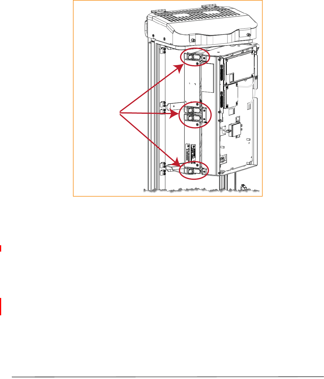
ConnectLatchesonDual‐BayRFModules
ForDual‐BayRFModules,securefourlatches,asshowninFigure19.
Four latches in a
Dual-Band Dual-Slot
RF Module
Figure19.Dual‐BayRFModuleLatches
FlexWavePrismRemoteUnitRFModuleInstallationGuide Page35
TECP‐77‐141Issue6•300001744178RevF•July2014 ©2014TEConnectivity
LatchesonLegacyDual‐Bay40WRFModules
ForLegacyDual‐Bay40WRFModules,securefourlatches,asshowninFigure20.
Four latches in a
Legacy Dual-Slot 40W
RF Module
Figure20.LegacyDual‐Bay40WRFModuleLatches
VerifythattheRFModuleMountingHookisEngaged
1VerifythattheRFModuleMountingHookisengagedcorrectlybypullingthemoduleawayfromtheheatsink.
TheRFModuleshouldnotmove.IftheRFModulemovesduringthischeck,repeatallthestepsstartingat
“InstalltheRFModuleintothePrismRemoteChassis”onpage25throughthisstep.
ConnecttheRFModuleCables
ThestepstoconnecttheRFModulecableshavebeenseparatedintotwodifferentprocedures;followthesteps
thatcorrespondtotheRFModulebeinginstalled.
•“ConnectingCablesinaSingle‐BayRFModuleInstallation”onpage36
•“ConnectingCablesinaDual‐BayRFModuleInstallation”onpage39.

Page36 FlexWavePrismRemoteUnitRFModuleInstallationGuide
©2014TEConnectivity TECP‐77‐141Issue6•300001744178RevF•July2014
ConnectingCablesinaSingle‐BayRFModuleInstallation
1PositionthecablessothattheyareundertherightedgeoftheRFModule,pointingup.
2Followtheruleslistedin“UnderstandingtheRFModuleCables”onpage14.
3ConnecttheRFModulecables,inthefollowingorder:
aConnecttheMODNTX0/RX0cabletotheRFModule.
iInserttheN‐StylePlugoftheMODNTX0/RX0cableintotheTX0/RX0N‐StyleJackoftheRFModule.
ii Turnthecouplingnutoftheplugclockwisetothreadontothejackandfinger‐tighten.
iii Torquecouplingnutto8±1in‐lbstoensurefullconnection.
NOTE: InsufficienttorqueappliedtoRFModuleconnectionscanresultinelevatedinsertion/returnlossand
higherthannormalVSWRreportedbythesystem.
bConnecttheMODNTX1/RX1cabletotheRFModule.
iIfaTX1/RX1RFModuleconnectionisavailable,inserttheN‐StylePlugoftheMODNTX1/RX1cable
intotheTX1/RX1N‐StyleJackoftheRFModule.IfRFModuleconnectionisnotavailable,constrain
theMODNTX1/RX1cabletoaccompanyingcablesusingatiewrapsoitcannotbepinchedorprevent
thePRUdoorfromclosing.
ii Turnthecouplingnutoftheplugclockwisetothreadontothejackandfinger‐tighten.
iii Torquecouplingnutto8±1in‐lbstoensurefullconnection.
NOTE: InsufficienttorqueappliedtoRFModuleconnectionscanresultinelevatedinsertion/returnlossand
higherthannormalVSWRreportedbythesystem.
cConnecttheLVDSCablestotheRFModule.
iConnecttheMODNDIVLVDSCabletotheDIVreceptacleoftheRFModulebyinsertingandsliding
inuntilfullyseated.
NOTE: AlwaysconnecttheDiversityLVDSCablewiththeRFModule.
ii ConnecttheMODNPRIMLVDSCabletothePRIMconnector,followingthesamestepsasabove.
NOTE: FullinsertioncanberecognizedbyanaudibleclickastheLVDSCableConnectorlocksintotheRF
ModuleReceptacle.ThiscanbeverifiedbylightlypullingbackontheLVDSconnectorwhilemakingsure
nottodepressthereleasetrigger.Whenfullyinserted,thecableshouldnotbeabletoberemovedfrom
thereceptacle.
dConnectthePowerCableConnectortothePWRreceptacleoftheRFModulebyinsertingandslidingin
untilfullyseated.
NOTE: FullinsertioncanberecognizedbyanaudibleclickasthePowerCableConnectorlocksintotheRF
ModuleReceptacle.ThiscanbeverifiedbylightlypullingbackonthePowerCableConnectorwhile
makingsurenottodepressthereleasetriggersontheendsoftheconnector.Whenfullyinserted,the
cableshouldnotbeabletoberemovedfromthereceptacle.
FlexWavePrismRemoteUnitRFModuleInstallationGuide Page37
TECP‐77‐141Issue6•300001744178RevF•July2014 ©2014TEConnectivity
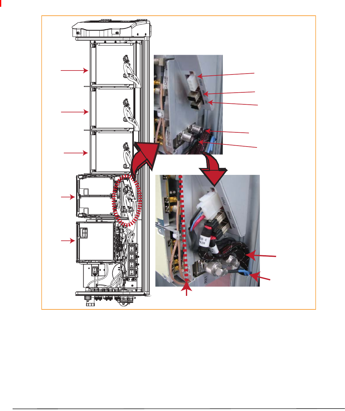
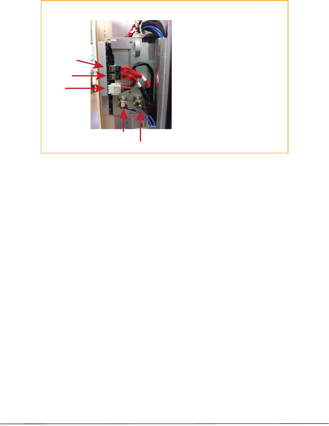
RefertothegraphicthatcorrespondstotheRFModulebeinginstalledintoasinglebayofthePRU:
•Single‐BayRFModule:Figure21
•HDMRFModule:Figure22onpage38
Bay A
Bay D
Bay C
Bay B
SeRF
Module
TX0/RX0
RX1
DIV
PRIM
PWR
Note routing of
high-speed cables
Note bend
radii ≥ 1-inch
Edge of Connector Interface Panel
Cable connections for a Single-Slot RF Module
Figure21.CableConnectionsforSingle‐BayRFModules
CAUTION! EnsurethatallcablebendsarebelowthetopedgeoftheConnectorInterfacePanelasindicatedbythedashed
lineintheprecedingfigure.FailuretocorrectlypositionthecablescouldinhibitclosingthePRUdoor,whichcan
resultindamagetothecables.
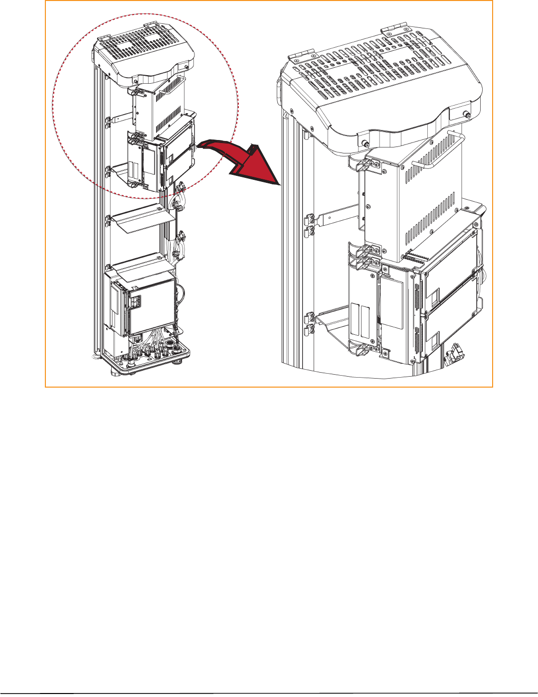
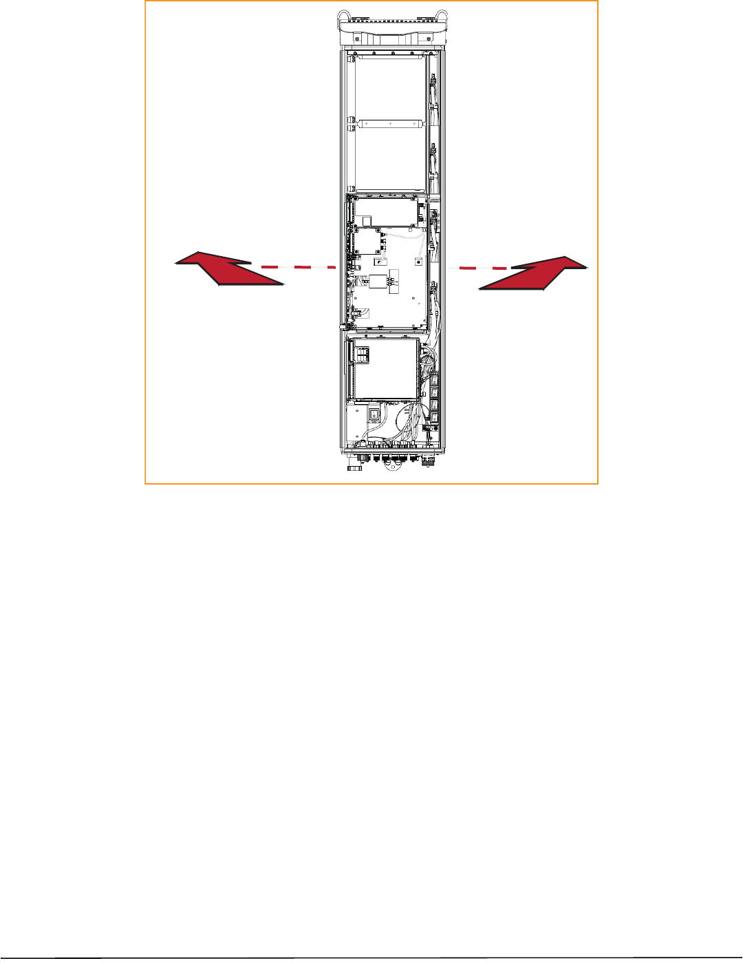
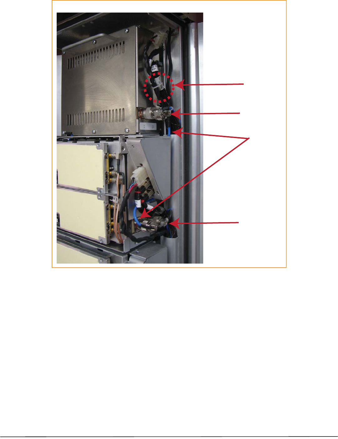
Cable Connections for an HDM RF Module
TX0/RX0
TX1/RX1
POWER
DATA 1 (DIV)
DATA 0 (PRIM)
Cable Connection Notes
• Always connect the Power cable.
• Always connect the two LVDS cables: PRIM and DIV.
• SISO requires one RF cable (TX1/RX1).
• MIMO and Dual-Band require two RF cables
(TX1/RX1 and TX0/RX0).
Page38 FlexWavePrismRemoteUnitRFModuleInstallationGuide
©2014TEConnectivity TECP‐77‐141Issue6•300001744178RevF•July2014
Figure22.CableConnectionsforHDMRFModules

FlexWavePrismRemoteUnitRFModuleInstallationGuide Page39
TECP‐77‐141Issue6•300001744178RevF•July2014 ©2014TEConnectivity
ConnectingCablesinaDual‐BayRFModuleInstallation
1PositionthecablessothattheyareundertherightedgeoftheRFModule,pointingup.
2Followtheruleslistedin“UnderstandingtheRFModuleCables”onpage14.
3Followtheruleslistedbelow;theserulesareapplicableonlytoDual‐BayRFModules.
•Table13listshowtocorrectlyconnectHDMRFModulestotheAntennaportsonthebottomofthePRU.
Table13.HDMAntennaPortMapping
RFModuleCatalog#Description TX0/RX0 TX1/RX1
DUAL20WSMR800/PCS1900 1900 800
HDMMIMO20W1900PCSRFMODULE Path1Path2
HDMMIMO20W2100AWSRFMODULEPath1Path2
HDMDUAL20W850/1900RFMODULE 1900 850
HDMMIMO20W700LOWERABCRFMODULE Path1Path2
HDMDUAL20W,700ABC/700UC,RFMODULE 700lABC 700uC
HDMMIMO20W700UPPERCMODULE Path1Path2
(1) ADual20WSMR800/PCS1900RFModule(FWP‐441T841MOD)requiresaFlexWaveNotchFilter
(FWP‐SPRINTFILTER)betweenthePRUandtheantennatoprovideprotectionfromspuriousemissions
inthePublicSafetybandbelow861.35MHzandtheCellularbandabove869.5MHz.Informationon
howtoinstalltheNotchFilterisprovidedin“FlexWaveNotchFilter(FWP‐SPRINTFILTER)”onpage44.
•TheupperRFModuleshelfwilleithernotbepresent(factoryinstalledmodule)orwillberemovedprior
toinstallation(fieldinstalledmodule).
•TheMODNTX0/RX0cableforthelowerRFModulebaywillneedtobeconnectedtotheMODNTX0/RX0
N‐StyleRFconnectionoftheDual‐BayRFModule.
•ConstraintheMODNTX1/RX1cabletotheexistingcablesusingatiewrapsuchsoitcannotbepinched
orpreventthePRUdoorfromclosing.DonotcutorattempttootherwiseremovethisRFcable.
•TheRFcablesandtwoLVDScablesofthelowerRFModulebayarenotusedwheninstallingaDual‐Bay
RFModule.
4Workingfromthebottomconnectorup,connecttheRFModulecables,asfollows:
aConnecttheMODNTX1/RX1cabletotheRFModule.
iConstraintheMODNTX1/RX1cableofthelowerRFModulebaytoaccompanyingcablesusingatie
wrapsoitcannotbepinchedorpreventthePRUdoorfromclosing.
ii ConnecttheMODNTX1/RX1cabletotheTX1/RX1orN/C,N‐StyleJackoftheupperRFModulebay.
iii Turnthecouplingnutoftheplugclockwisetothreadontothejackandfinger‐tighten.
iv Torquecouplingnutto8±1in‐lbstoensurefullconnection.
NOTE: InsufficienttorqueappliedtoRFModuleconnectionscanresultinelevatedinsertion/returnlossand
higherthannormalVSWRreportedbythesystem.
FWP‐441T841MOD(1)
FWP‐84MT000MOD
FWP‐A4MT000MOD
FWP‐C4MT000MOD
FWP‐L4MT000MOD
FWP‐L4MTU4MMOD
FWP‐U4MT000MOD

Page40 FlexWavePrismRemoteUnitRFModuleInstallationGuide
©2014TEConnectivity TECP‐77‐141Issue6•300001744178RevF•July2014
bConnecttheMODNTX0/RX0cabletotheRFModule.
iInserttheN‐StylePlugoftheMODNTX0/RX0cableintotheTX0/RX0N‐StyleJackofthelowerRF
Module bay. If RF Module connection is not available, constraintheMODNTX0/RX0cableto
accompanyingcablesusingatiewrapsoitcannotbepinchedorpreventthePRUdoorfromclosing.
ii Turnthecouplingnutoftheplugclockwisetothreadontothejackandfinger‐tighten.
iii Torquecouplingnutto8±1in‐lbstoensurefullconnection.
NOTE: InsufficienttorqueappliedtoRFModuleconnectionscanresultinelevatedinsertion/returnlossand
higherthannormalVSWRreportedbythesystem.
cConnecttheLVDSCablestotheRFModule.
iIfavailable,connectthe MODNDIVLVDSCableto theDIV receptacle ofthelowerRFModuleby
insertingandslidinginuntilfullyseated.IfDIVreceptacleisnotavailable,constraintheMODNDIV
LVDSCabletoaccompanyingcablesusingatiewrapsoitcannotbepinchedorpreventthePRUdoor
fromclosing.
ii ConnecttheMODNDIVLVDSCabletotheDIVreceptacleoftheupperRFModulebyinsertingand
slidinginuntilfullyseated.IfDIVreceptacleisnotavailable,constraintheMODNDIVLVDSCableto
accompanyingcablesusingatiewrapsoitcannotbepinchedorpreventthePRUdoorfromclosing.
iii Ifavailable,connecttheMODNPRIMLVDSCabletothePRIMreceptacleoftheupperRFModuleby
insertingandslidinginuntilfullyseated.IfDIVreceptacleisnotavailable,constraintheNPRIMLVDS
CabletoaccompanyingcablesusingatiewrapsoitcannotbepinchedorpreventthePRUdoorfrom
closing.
NOTE: FullinsertioncanberecognizedbyanaudibleclickastheLVDSCableConnectorlocksintotheRF
ModuleReceptacle.ThiscanbeverifiedbylightlypullingbackontheLVDSconnectorwhilemakingsure
nottodepressthereleasetrigger.Whenfullyinserted,thecableshouldnotbeabletoberemovedfrom
thereceptacle.
dConnectthePowercabletotheRFModule.
iConnectthePowerCableConnectortothePWRreceptacleofthelowerRFModulebyinsertingand
slidinginuntilfullyseated.
ii ConnectthePowerCableConnectortothePWRreceptacleoftheupperRFModulebyinsertingand
slidinginuntilfullyseated.IfPWRreceptacleisnotavailable, constrain the Power Cable to
accompanyingcablesusingatiewrapsoitcannotbepinchedorpreventthePRUdoorfromclosing.
NOTE: FullinsertioncanberecognizedbyanaudibleclickasthePowerCableConnectorlocksintotheRF
ModuleReceptacle.ThiscanbeverifiedbylightlypullingbackonthePowerCableConnectorwhile
makingsurenottodepressthereleasetriggersontheendsoftheconnector.Whenfullyinserted,the
cableshouldnotbeabletoberemovedfromthereceptacle.
RefertothegraphicthatcorrespondstotheRFModulebeinginstalledinaDual‐Bay:
•Dual‐BayRFModule:Figure23onPage41
•LegacyDual‐Bay40WRFModule:Figure24onPage42.
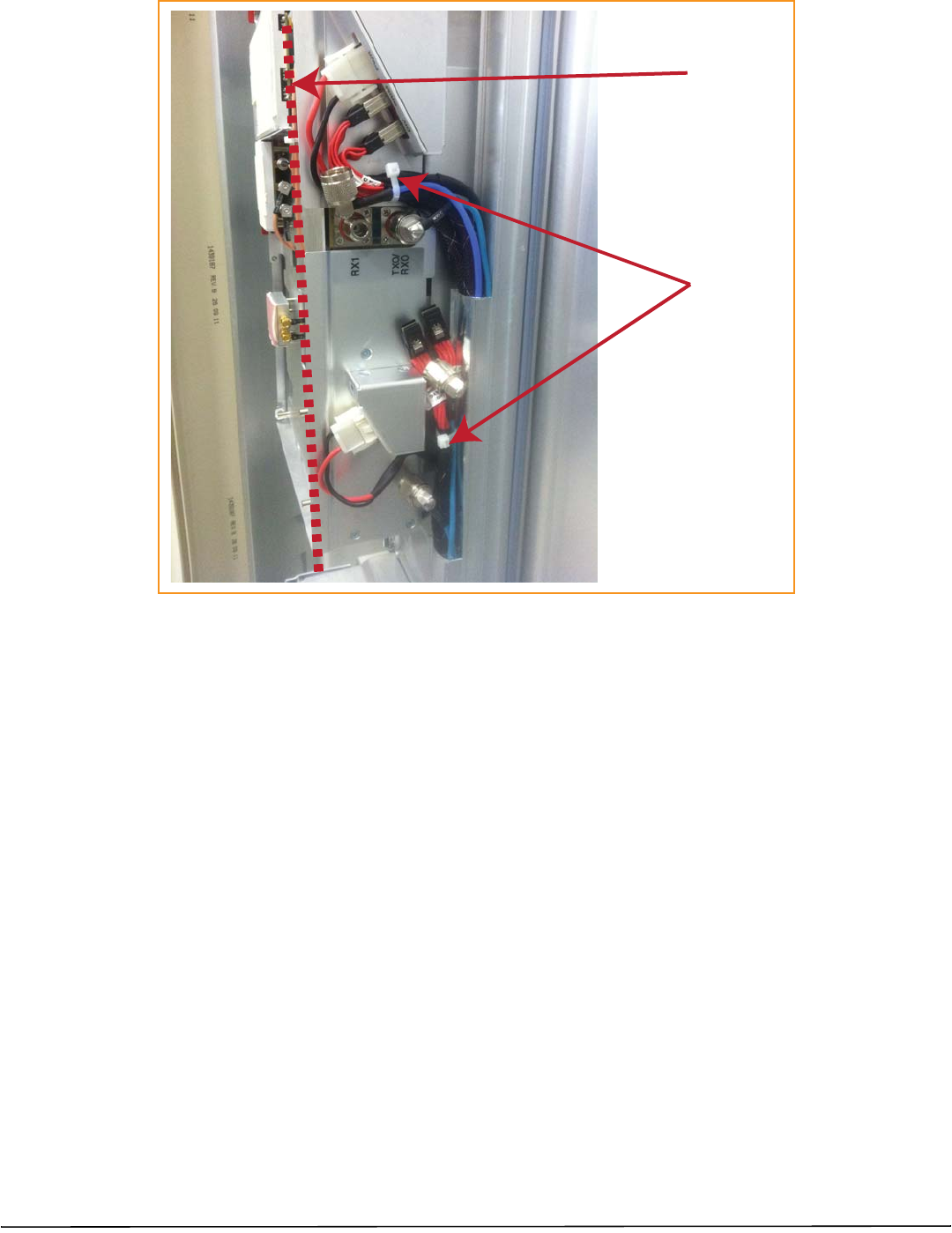
Cable Connections for a Dual-Slot RF Module
Tie wrap
Factory-installed
RX1 cable
Two N-Type
RF connectors
N-Type
RF connector
FlexWavePrismRemoteUnitRFModuleInstallationGuide Page41
TECP‐77‐141Issue6•300001744178RevF•July2014 ©2014TEConnectivity
Figure23.CableConnectionsforDual‐BandDual‐BayRFModules
Tie wrap around
factory-installed
RX1 cable
Keep cable bends
behind the edge
of the Connector
Interface Panel
Page42 FlexWavePrismRemoteUnitRFModuleInstallationGuide
©2014TEConnectivity TECP‐77‐141Issue6•300001744178RevF•July2014
Figure24.CableConnectionsforLegacyDual‐Bay40WRFModules
CAUTION! EnsurethatallcablebendsarebelowthetopedgeoftheConnectorInterfacePanelasindicatedbythedashed
lineintheprecedingfigure.FailuretocorrectlypositionthecablescouldinhibitclosingthePRUdoor,whichcan
resultindamagetothecables.
FlexWavePrismRemoteUnitRFModuleInstallationGuide Page43
TECP‐77‐141Issue6•300001744178RevF•July2014 ©2014TEConnectivity
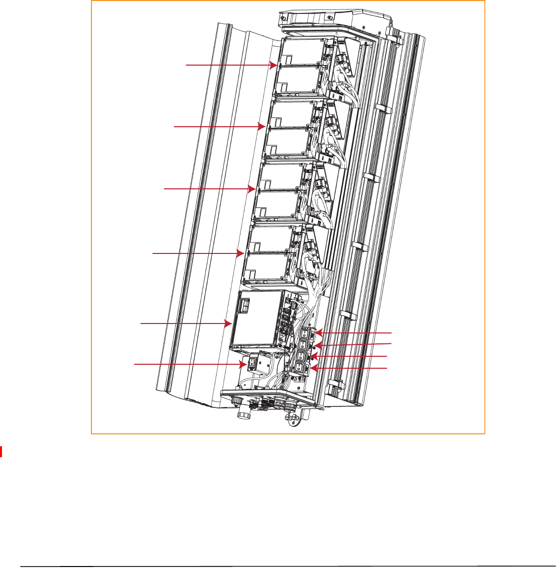
PowerontheRFModule
1FollowtheruleslistedbelowtotogglethePowerswitchthatcorrespondstotheRFModuletoitsONposition.
•ForDual‐BandDual‐BayRFModules,usethePowerswitchforthelowermodule.Forexample,topower
upaDual‐BayRFModuleincombinedbaysC+DinaQuad‐Baychassis,turnONDCPowerswitchforMod
C;leavetheDCPowerswitchforModDOFF.
•ALegacyDual‐Bay40WRFModuleusesthePowerSuppliesinbothbays.IftheLegacyDual‐Bay40WRF
ModuleisinstalledinbaysC+D,turnONthePowerswitchforModCandModD.
Bay A
SeRF
Module
AC/DC Power
switch for
PRU chassis
DC Power switch for Bay A
DC Power switch for Bay B
DC Power switch for Bay C
DC Power switch for Bay D
Bay B
Bay C
Bay D
2Repeatallthestepsin“InstalltheRFModule(s)”onpage20toinstallotherRFModules.
Page44 FlexWavePrismRemoteUnitRFModuleInstallationGuide
©2014TEConnectivity TECP‐77‐141Issue6•300001744178RevF•July2014
FLEXWAVENOTCHFILTER(FWP‐SPRINTFILTER)
TheDUAL20WSMR800/PCS1900RFModule(FWP‐441T841MOD)requiresaFlexWaveNotchFilter
(FWP‐SPRINTFILTER)betweenthePrismRemoteUnitandtheantennatoprovideprotectionfromspurious
emissionsinthePublicSafetybandbelow861.35MHzandtheCellularbandabove869.5MHz.TheNotchFilter
shipsautomaticallywiththeDUAL20WSMR800/PCS1900RFModule.
HerearesomeinstallationtipsfortheNotchFilter:
•YoucanusethesamemountingmethodtomounttheNotchFilterasyouusedtomountthePRU.
•MounttheNotchFilterverticallywiththeN‐typefemaleconnectorsatthebottom.
•TherearetwoGroundlugsontheNotchFilter,whichareonthebackofthetwomountingbrackets.Follow
localpracticetogroundtheNotchFilter.
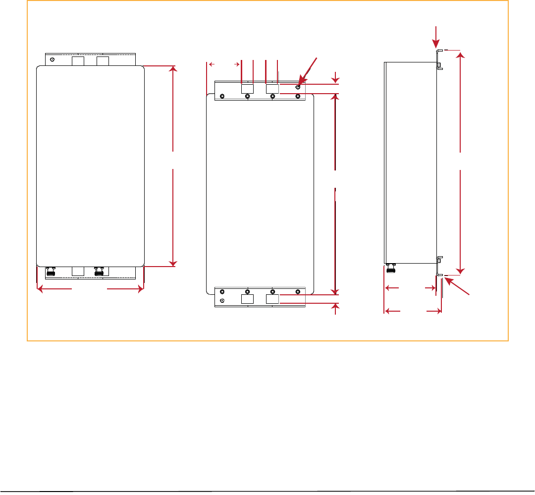
Figure25providesthedimensionsrequiredtocreateamountingtemplate.
16.0 ±.1
.70
.70
2.805 .95 .95
1.00
2 Locaons
5/16-18
Ground Lug
Front View
Side View
Back View
4.55
17.9 ±.1
4.10 Mounng
Bracket
15.93
8.51
Mounng
Bracket
Figure25.NotchFilterMountingDimensions
FlexWavePrismRemoteUnitRFModuleInstallationGuide Page45
TECP‐77‐141Issue6•300001744178RevF•July2014 ©2014TEConnectivity
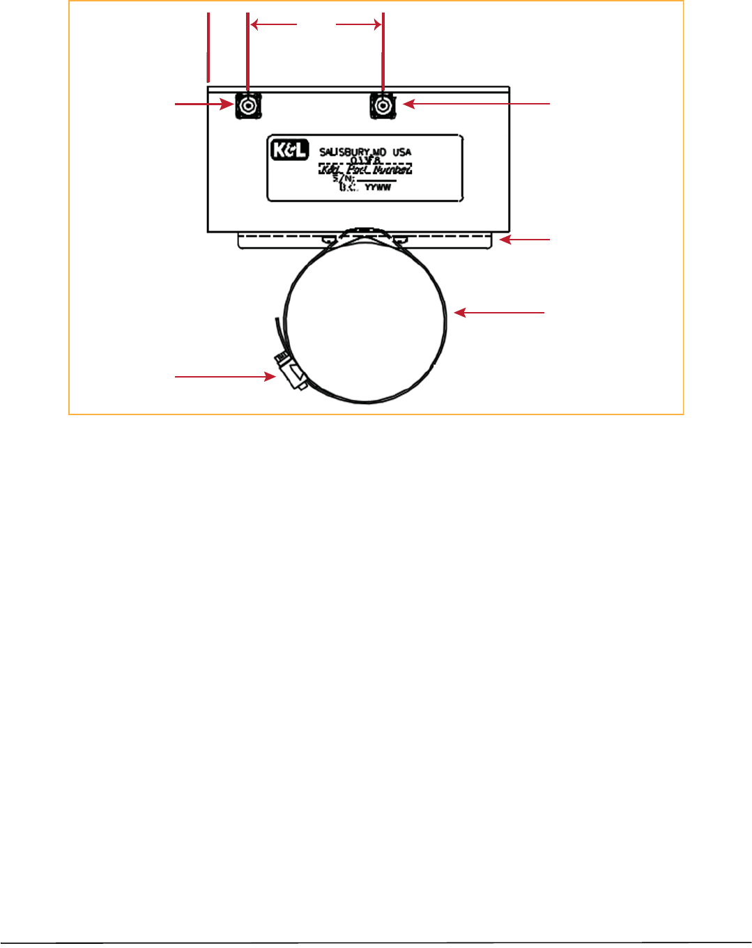
Figure26illustrateshowtopolemounttheNotchFilter.
1.13 3.81
N-Type
Female
Connector
N-Type
Female
Connector
Band must be long enough
to wrap around the pole
Boom View of
Notch Filter
Hose clamp sized for
installaon requirement
Mounng Bracket
Figure26.PoleMountingaNotchFilter

Page46 FlexWavePrismRemoteUnitRFModuleInstallationGuide
©2014TEConnectivity TECP‐77‐141Issue6•300001744178RevF•July2014
STANDARDSCERTIFICATION
FCC
ThisequipmentcomplieswiththeapplicablesectionsofTitle47CFRPart15(HostUnit),Part22(800MHzCellular),Part
24(1900MHz‐PCS),Part90(800/900‐SMR),andPart27(2100MHz‐AWS)&(700MHz‐LTE).
IC
ThisequipmentcomplieswiththeapplicablesectionsofRSS‐131‐ZoneEnhancersfortheLandMobileService.Theterm
“IC:”beforetheradiocertificationnumberonlysignifiesthatIndustryCanadaTechnicalSpecificationsweremet.
TheManufacturer'sratedoutputpowerofthisequipmentisforsinglecarrieroperation.Forsituationswhenmultiple
carriersignalsarepresent,theratingwouldhavetobereducedby3.5dB,especiallywheretheoutputsignalisre‐radiated
andcancauseinterferencetoadjacentbandusers.Thispowerreductionistobebymeansofinputpowerorgainreduction
andnotbyanattenuatorattheoutputofthedevice.
Note:TocomplywithMaximumPermissibleExposure(MPE)requirements,themaximumcompositeoutputfromthe
antennacannotexceed1000WattsERP(LTE,CellularandSMR),theantennacannotexceed1640WattsEIRP(PCSand
AWS),andtheantennamustbepermanentlyinstalledinafixedlocationthatprovidesatleast6meters(20feet)of
separationfromallpersons.
UL/CUL
Thiswillbeinstalledinarestrictedaccesslocation.ThisequipmentcomplieswithType4,perULandCUL50,Standardfor
EnclosuresforElectricalEquipment.ThisequipmentprovidesthedegreeofprotectionspecifiedbyIP66asdefinedinIEC
Publication529.
FDA/CDRH
ThisequipmentusesaClass1LASERaccordingtoFDA/CDRHRules.Thisproductconformstoallapplicablestandardsof
21CFRPart1040.
Caution:Modificationsnotexpresslyapprovedbythepartyresponsibleforcompliancecouldvoidtheuser'sauthorityto
operatetheequipment.
EUHarmonizedStandards
MeetsessentialrequirementsofR&TTE1999/5/EC.
•Article3.1a—Theprotectionofthehealthandthesafetyoftheuserandanyotherperson,includingtheobjectiveswith
respecttosafetyrequirementscontainedinDirective2006/95/EC,butwithnovoltagelimitapplying.
•Article3.1b—TheprotectionrequirementswithrespecttoelectromagneticcompatibilitycontainedinDirective
2004/108/EC.
•Article3.2—Inaddition,radioequipmentshallbesoconstructedthatiteffectivelyusesthespectrumallocatedto
terrestrial/spaceradiocommunicationandorbitalresourcessoastoavoidharmfulinterference.
EMCStandards
EN55022andEN55024(CEmarked)
SafetyStandards
ThisequipmentcomplieswithIEC60950‐1,2NDEdition+Amendment1(CEmarked)andwithUL60950‐1,2NDEdition+
Amendment1(FilenumberE174166)(USAandCanada)

FlexWavePrismRemoteUnitRFModuleInstallationGuide Page47
TECP‐77‐141Issue6•300001744178RevF•July2014 ©2014TEConnectivity
ACCESSINGUSERDOCUMENTATIONONTHETECUSTOMERPORTAL
YoucanaccessadditionaluserdocumentationontheTECustomerPortal,asdescribedbelow.
1ClickonthefollowingURLlink:
https://www.te.com/portal/wireless/
(Alternatively,entertheprecedingURLintoyourwebbrowser,andthenpressENTERonyourkeyboard.)
2AccesstotheCustomerPortalrequiresauseraccountandpassword.OntheSignInpage,dooneofthe
following:
•Ifyouhaveanaccount,intheAlreadyRegistered?SignInNowpanel,enteryourEmailandPassword,and
thenclickSignIn.
•Ifyoudon’thaveanaccount,underCreateanAccount,clickRegisterNowandfollowtheprompts.
3OntheWirelessCustomerPortalhomepageintheKnowledgeCenterpanel,clicktheManualsandDataSheets
link.
4OntheManualsandDataSheetspage,dothefollowing:
aIntheDocumentRepositorypanel,scrolltothesectionfortheproductlineofthedocumentthatyouwant
toaccess.
bClickonthetitleofthemanualthatyouwishtoopen.
c(Optional)SavethePDFtoyourcomputer.

Page48 FlexWavePrismRemoteUnitRFModuleInstallationGuide
©2014TEConnectivity TECP‐77‐141Issue6•300001744178RevF•July2014
CONTACTINGTECONNECTIVITY
TelephoneNumbers
Sales
AsiaPacific +65‐6294‐9948
France 0800914032
Germany 01802232923
Italy 0800782374
Spain 900983291
UnitedKingdom 0800960236
USAorCanada 1‐800‐366‐3891
Extension 73000
ConnectivityExtension 73475
WirelessExtension 73476
TechnicalSupport
USAorCanada 1‐800‐530‐9960
Elsewhere +1‐952‐917‐0761
OnlineAccess
CustomerPortal
https://www.te.com/portal/wireless/
TechnicalSupportforWirelessProducts
http://www.te.com/WirelessSupport