ADC Telecommunications PSM25TDL FWP-T4MT000MOD-L User Manual
ADC Telecommunications Inc FWP-T4MT000MOD-L
User Manual
Page 26 FlexWave Prism Remote Unit RF Module Installation Guide
©2015 TE Connectivity TECP-77-141 Issue 8 • 300001744178 Rev H • September 2015
Install the RF Module into the Prism Remote Chassis
1ȋȌ
Ǥ
NOTE: Always install RF Modules from the bottom up. Do not skip a bay, as this provides more efficient heat
dissipation.
2Ͷͷιǡ
ǡǡǤ
•Ǧǣͳͳʹ
•ǣͳʹʹ
•Ǧǣͳ͵ʹͺ
•ǦͶͲǣͳͶʹͻǤ
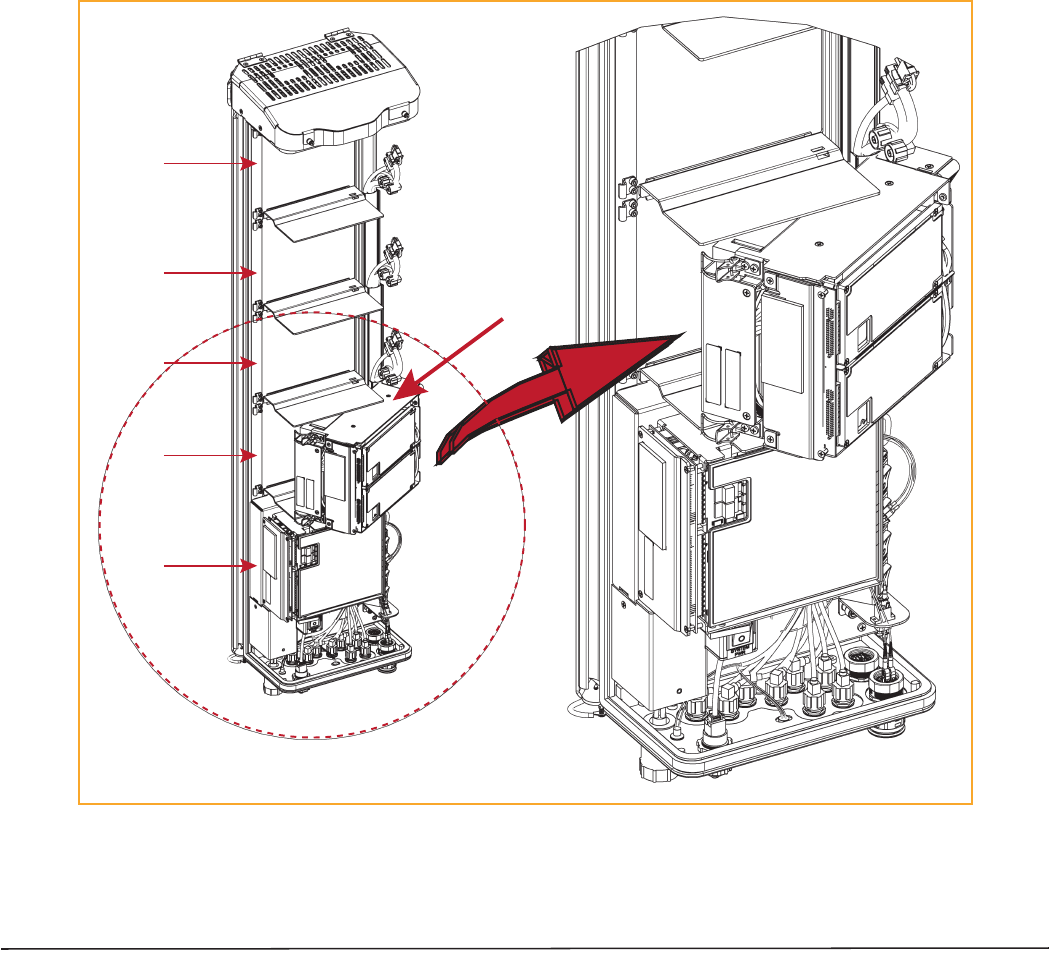
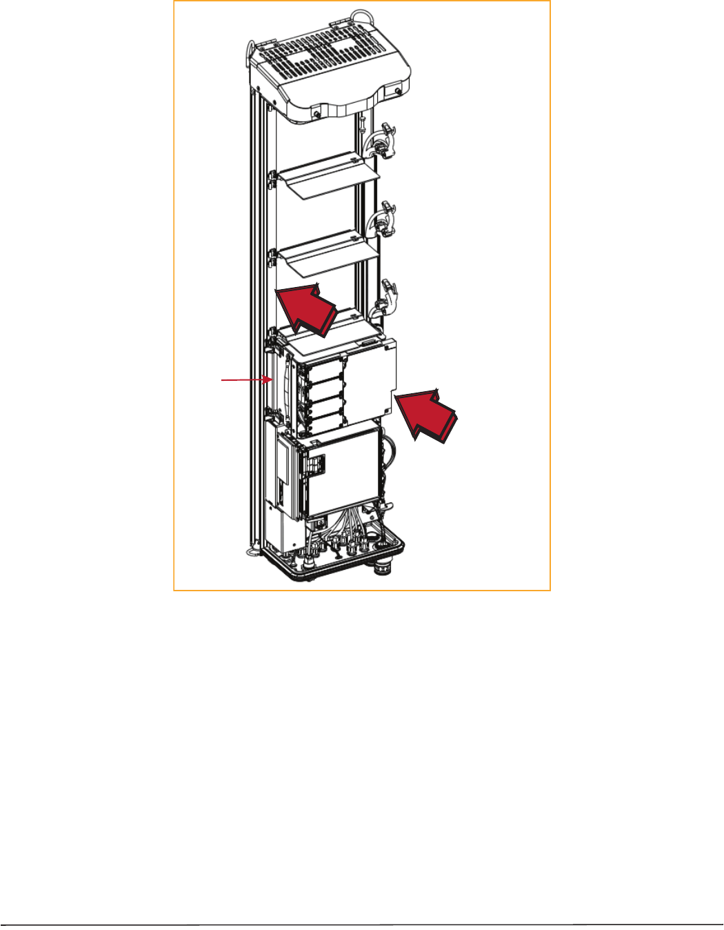
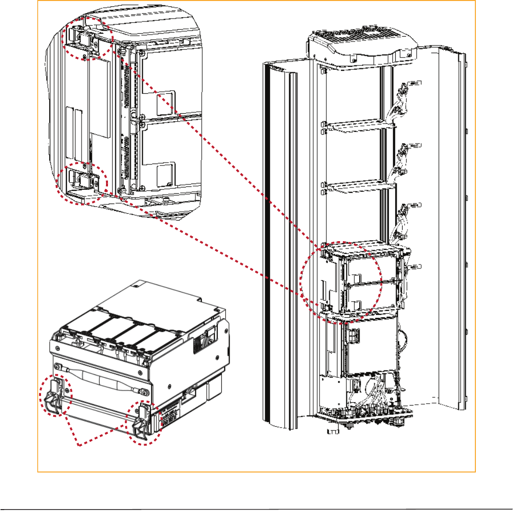
Figure 11. Installing a Single-Bay RF Module
Bay C
Bay D
SeRF
Module
Bay A
Bay B
Single-Slot
RF Module
Heat Sink
FlexWave Prism Remote Unit RF Module Installation Guide Page 27
TECP-77-141 Issue 8 • 300001744178 Rev H • September 2015 ©2015 TE Connectivity
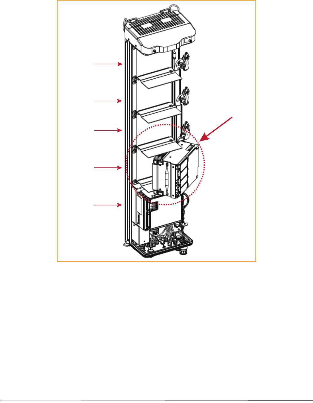
Figure 12. Installing an HDM RF Module
Bay C
Bay D
SeRF Module
Bay A
Bay B
HDM RF Module
Page 28 FlexWave Prism Remote Unit RF Module Installation Guide
©2015 TE Connectivity TECP-77-141 Issue 8 • 300001744178 Rev H • September 2015
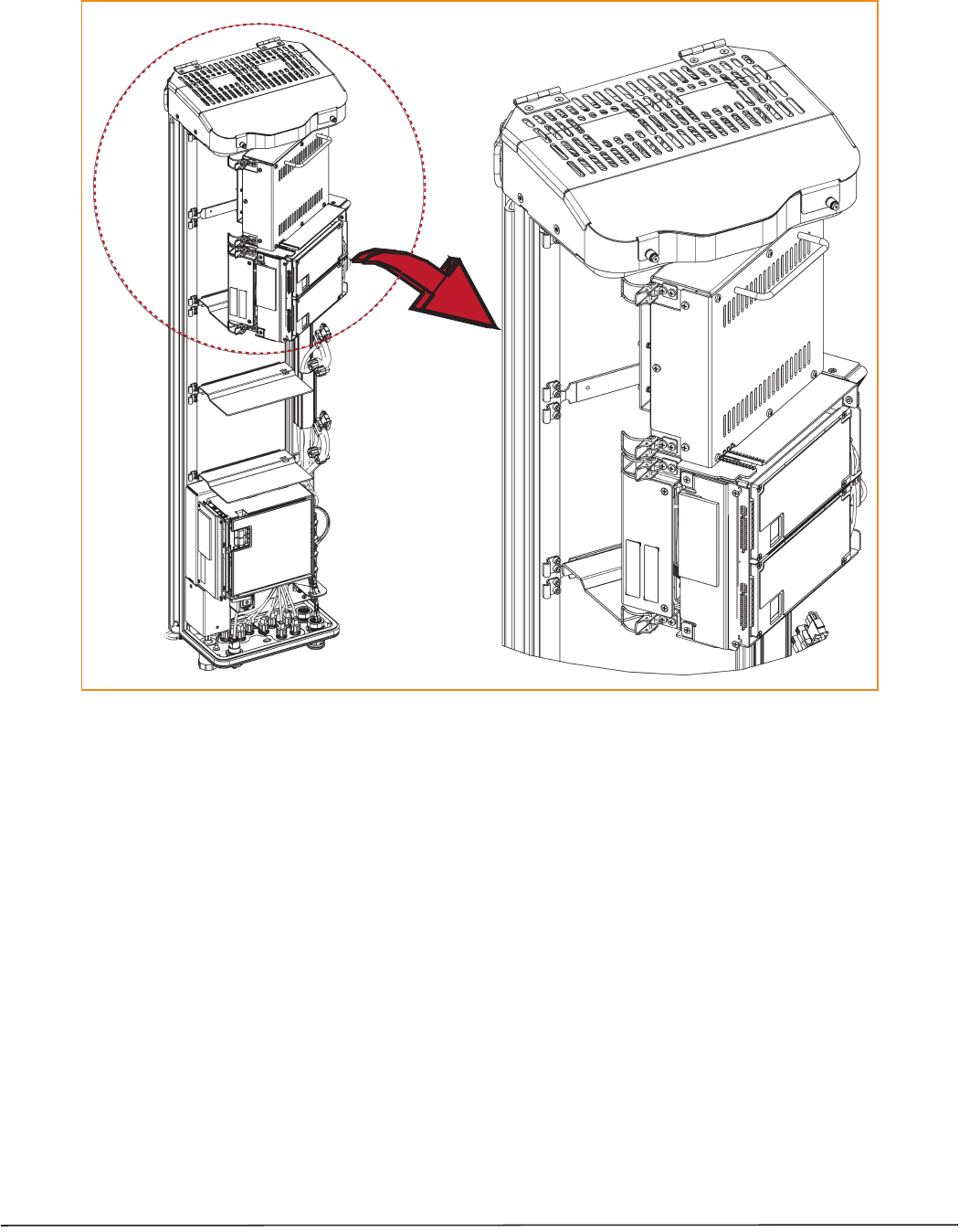
Figure 13. Installing a Dual-Bay RF Module
Installing a Dual-Band
Dual-Slot RF Module
FlexWave Prism Remote Unit RF Module Installation Guide Page 29
TECP-77-141 Issue 8 • 300001744178 Rev H • September 2015 ©2015 TE Connectivity
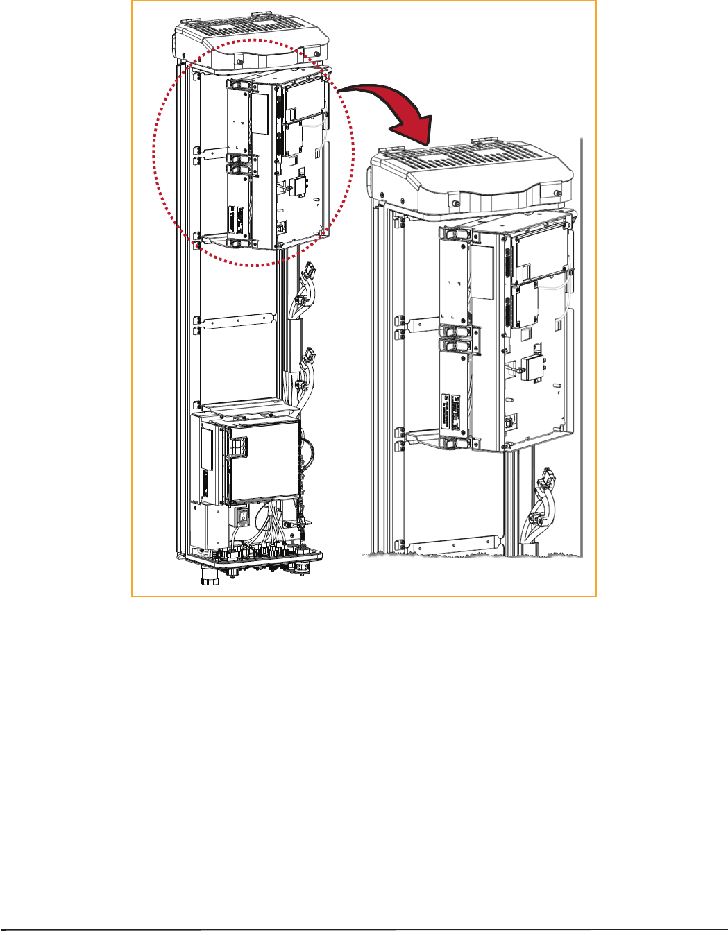
Figure 14. Installing a Legacy Dual-Bay 40W RF Module
Page 30 FlexWave Prism Remote Unit RF Module Installation Guide
©2015 TE Connectivity TECP-77-141 Issue 8 • 300001744178 Rev H • September 2015
3ǡ
Ǥ
4ǡ
ǣ
•Ǧǡͳͷ͵ͳǤ
•ǡͳ͵ʹǤ
•Ǧǡͳ͵͵ǡǦͶͲ
Ǥ
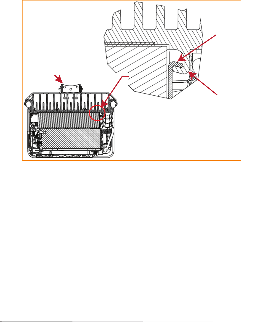
CAUTION! Make sure the RF Module is seated correctly in the Module shelf. Incorrect alignment of the RF Module
can cause the RF Module to fail due to overheating.
•The front edge of the RF Module should be parallel with the shelf above it.
•The Mounting Hook on the RF Module should be fully engaged with the Receiving flange on the Remote Unit
chassis.
•An incorrectly seated RF Module makes closing the Prism door difficult. If you later cannot shut the Remote
Unit door, verify that the RF Module is installed correctly.
RF Module
MounƟng
hook
Chassis
Receiving
flange
MounƟng Bracket at
back of the PRU
(View is looking down into the
PRU chassis from the top.)
FlexWave Prism Remote Unit RF Module Installation Guide Page 31
TECP-77-141 Issue 8 • 300001744178 Rev H • September 2015 ©2015 TE Connectivity
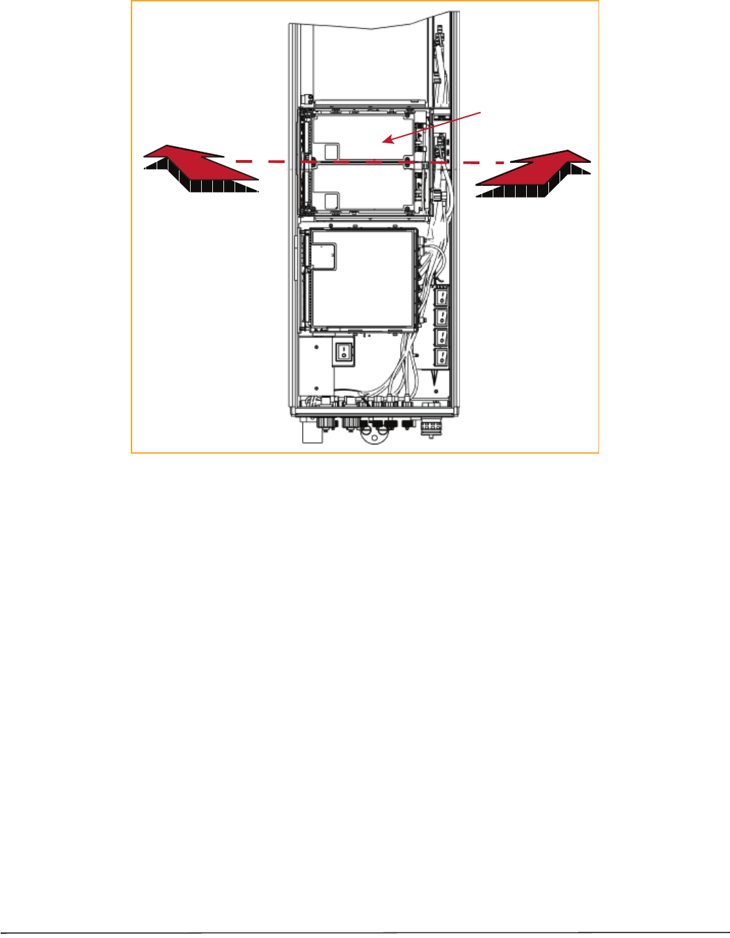
Figure 15. Seating a Single-Bay RF Module
Push the RF Module
back into the chassis
unƟl it can go no further.
Single-Slot
RF Module
Page 32 FlexWave Prism Remote Unit RF Module Installation Guide
©2015 TE Connectivity TECP-77-141 Issue 8 • 300001744178 Rev H • September 2015
Figure 16. Seating an HDM RF Module
Push the HDM RF Module
back into the chassis
unƟl it can go no further.
HDM
RF Module
FlexWave Prism Remote Unit RF Module Installation Guide Page 33
TECP-77-141 Issue 8 • 300001744178 Rev H • September 2015 ©2015 TE Connectivity
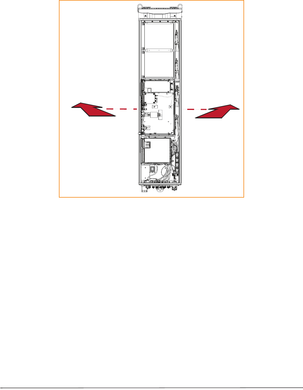
Figure 17. Seating a Dual-Bay RF Module
Push the RF Module back
into the chassis unƟl it can
go no further.
Page 34 FlexWave Prism Remote Unit RF Module Installation Guide
©2015 TE Connectivity TECP-77-141 Issue 8 • 300001744178 Rev H • September 2015
Secure RF Module Latches
1ǡǡ
ǣ
•DzǦdz͵Ͷ
•DzǦdz͵ͷǤ
Connect Latches on Single-Bay and HDM RF Modules
ǦǡǡͳͺǤ
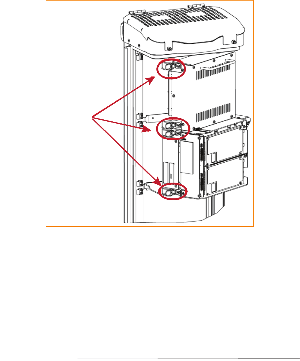
Figure 18. Latches on Single-Bay and HDM RF Modules
Two latches on Single-Slot
RF Modules
Two latches on
HDM RF Modules
FlexWave Prism Remote Unit RF Module Installation Guide Page 35
TECP-77-141 Issue 8 • 300001744178 Rev H • September 2015 ©2015 TE Connectivity
Connect Latches on Dual-Bay RF Modules
ǦǡǡͳͻǤ
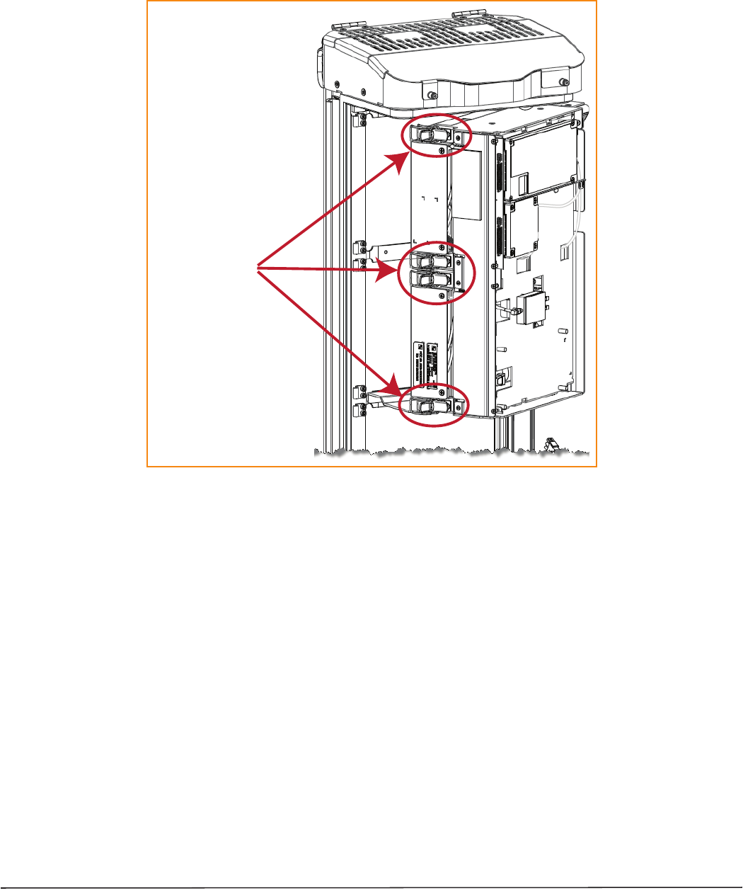
Figure 19. Dual-Bay RF Module Latches
Four latches in a
Dual-Band Dual-Slot
RF Module
Page 36 FlexWave Prism Remote Unit RF Module Installation Guide
©2015 TE Connectivity TECP-77-141 Issue 8 • 300001744178 Rev H • September 2015
Latches on Legacy Dual-Bay 40W RF Modules
ǦͶͲǡǡʹͲǤ
Figure 20. Legacy Dual-Bay 40W RF Module Latches
Verify that the RF Module Mounting Hook is Engaged
Ǥ
ǤǡDz
dzʹǤ
Connect the RF Module Cables to the PRU Chassis
Ǣ
Ǥ
•DzǦdz͵
•DzǦdzͶͲǤ
Four latches in a
Legacy Dual-Slot 40W
RF Module

FlexWave Prism Remote Unit RF Module Installation Guide Page 37
TECP-77-141 Issue 8 • 300001744178 Rev H • September 2015 ©2015 TE Connectivity
Connecting Cables in a Single-Bay RF Module Installation
1ǡǤ
2DzdzͳͺǤ
3ǡǤǡ
ǣǦǡʹͳ
͵ͺǡǡʹʹ͵ͻͳʹ͵ͻǤ
aNͲȀͲȋ
NͲȀͲNAǡBǡCǡDȌǤ
iǦͲȀͲͲȀͲǦǤ
ii ǦǤ
iii ͺάͳǦǤ
NOTE: Insufficient torque applied to RF Module connections can result in elevated insertion/return loss and
higher than normal VSWR reported by the system.
bNͳȀͳȋ
NͳȀͳNBǡCǡDȌǤ
iͳȀͳǡǦͳȀͳ
ͳȀͳǦǤǡ
ͳȀͳ
Ǥ
ii ǦǤ
iii ͺάͳǦǤ
NOTE: Insufficient torque applied to RF Module connections can result in elevated insertion/return loss and
higher than normal VSWR reported by the system.
cȄ
ǡ
ǤǦ
Ǥ
i
Ǥ
Ǥ
ii ǡǤ
Ǥ
iii
Ǥǡ
Ǥ
Page 38 FlexWave Prism Remote Unit RF Module Installation Guide
©2015 TE Connectivity TECP-77-141 Issue 8 • 300001744178 Rev H • September 2015
dǤ
iȋȌ
ȋDzdzʹͶȌǤ
iǡǤ
Ǥ
ii
Ǥǡ
Ǥ
4DzȋȌdzʹͳǤ
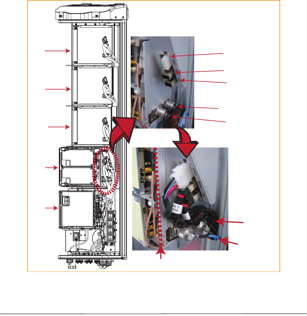
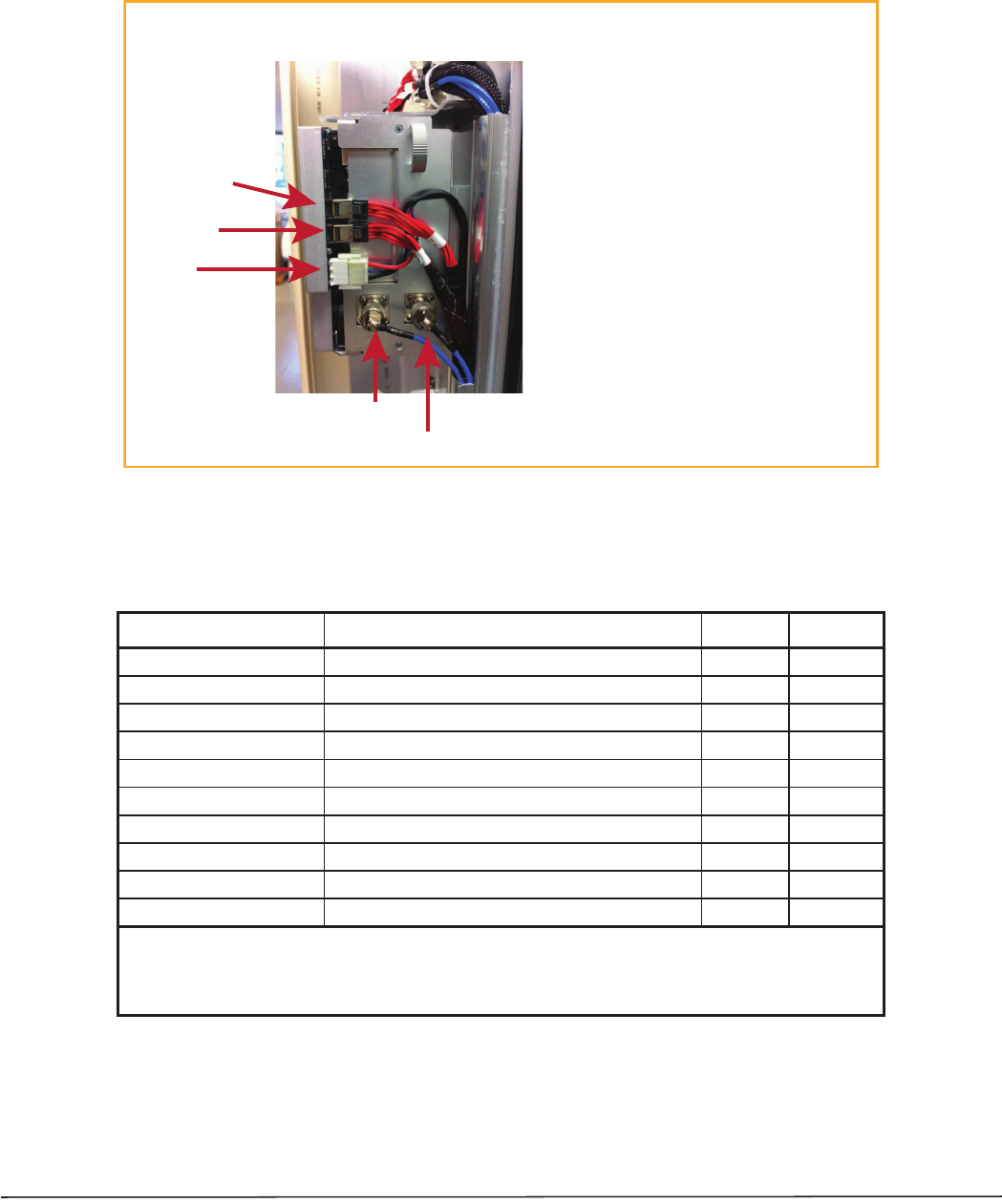
Figure 21. Cable Connections for Single-Bay RF Modules
Bay A
Bay D
Bay C
Bay B
SeRF
Module
TX0/RX0
TX1/RX1
DIV
PRIM
PWR
Note rouƟng of
high-speed cables
Note bend
radii ≥ 1-inch
Edge of Connector Interface Panel
Cable connecƟons for a Single-Slot RF Module
FlexWave Prism Remote Unit RF Module Installation Guide Page 39
TECP-77-141 Issue 8 • 300001744178 Rev H • September 2015 ©2015 TE Connectivity
CAUTION! Ensure that all cable bends are below the top edge of the Connector Interface Panel as indicated by the
dashed line in the preceding figure. Failure to correctly position the cables could inhibit closing the
Remote Unit door, which can result in damage to the cables.
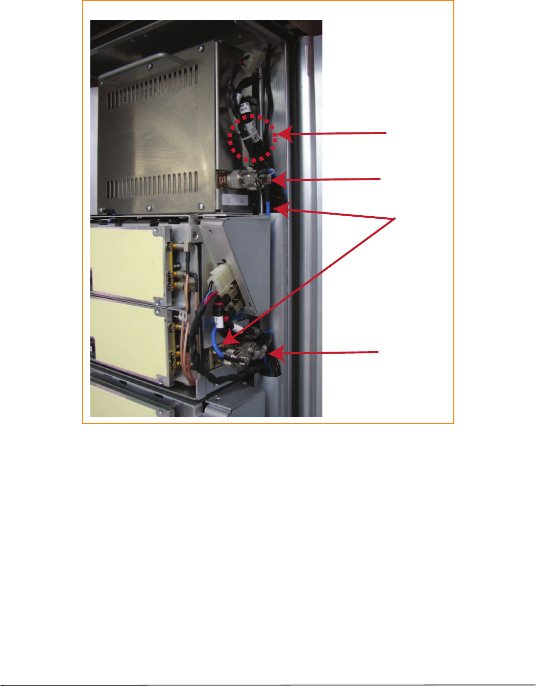
Figure 22. Cable Connections for HDM RF Modules
ͳʹǤ
Table 12. HDM Antenna Port Mapping
RF Module Catalog # Description TX0/RX0 TX1/RX1
F W P - L 4 M T 0 0 0 M O D 20W 700 lABC Module, MIMO HDM, Single-Bay Path 1 Path 2
F W P - U 4 M T 0 0 0 M O D 20W 700 uC Module, MIMO HDM, Single-Bay Path 1 Path 2
F W P - L 4 M T U 4 M M O D 20W 700 lABC/700uC, Dual, Single-Bay 700 lABC 700 uC
F W P - 4 4 M T 0 0 0 M O D 20W 800 MIMO, Single Bay, with two External Filters Path 1 Path 2
F W P - 4 4 1 T 8 4 1 M O D (1) 20W 800 SMR/ 1900 PCS, Dual RF Module 1900 800
F W P - B 4 M T 0 0 0 M O D 20W 850 DUAL, MIMO, Single Bay Path 1 Path 2
F W P - C 4 M T 0 0 0 M O D 20W 850 Cell/1900 PCS, Dual, Single-Bay 1900 850
F W P - 8 4 M T 0 0 0 M O D 20W 1900 PCS Dual MIMO, Single-Bay Path 1 Path 2
F W P - 8 4 M T A 4 M M O D 20W 1900/2100 Dual, Single Bay 2100 1900
F W P - A 4 M T 0 0 0 M O D 20W HDM AWS Band 4 MIMO, Single-Bay Path 1 Path 2
(1) A 20W 800 SMR/ 1900 PCS, Dual RF Module RF Module (FWP-441T841MOD) requires a FlexWave Notch
Filter (FWP-SPRINTFILTER) between the Remote Unit and the antenna to provide protection from spurious
emissions in the Public Safety band below 861.35 MHz and the Cellular band above 869.5 MHz. Information
on how to install the Notch Filter is provided in “FlexWave Notch Filter (FWP-SPRINTFILTER)” on page 47.
Cable ConnecƟons for an HDM RF Module
TX0/RX0
TX1/RX1
POWER
DATA 1 (DIV)
DATA 0 (PRIM)
Cable ConnecƟon Notes
• Always connect the Power cable.
• Always connect the two LVDS cables: PRIM and DIV.
• SISO requires one RF cable (TX0/RX0).
• MIMO and Dual-Band require two RF cables
(TX1/RX1 and TX0/RX0).

Page 40 FlexWave Prism Remote Unit RF Module Installation Guide
©2015 TE Connectivity TECP-77-141 Issue 8 • 300001744178 Rev H • September 2015
Connecting Cables in a Dual-Bay RF Module Installation
1ǡǤ
2DzdzͳͺǤ
3ǡǡǤǡ
ǦǣǦǡ
ʹ͵ͶʹǡǦͶͲǡʹͶͶ͵Ǥ
aNͳȀͳǦǦȋ
NͳȀͳNBǡCǡDȌǤ
iNͳȀͳ
Ǥ
ii NͳȀͳͳȀͳǦǤ
iii ǦǤ
iv ͺάͳǦǤ
NOTE: Insufficient torque applied to RF Module connections can result in elevated insertion/return loss and
higher than normal VSWR reported by the system.
bNͲȀͲȋ
NͲȀͲNAǡBǡCǡDȌǤ
iǦͲȀͲͲȀͲǦ
Ǥ ǡ ͲȀͲ
Ǥ
ii ǦǤ
iii ͺάͳǦǤ
NOTE: Insufficient torque applied to RF Module connections can result in elevated insertion/return loss and
higher than normal VSWR reported by the system.
cǤ
iǡ
Ǥǡ
Ǥ
Ǥ
ii
Ǥǡ
Ǥ
Ǥ

FlexWave Prism Remote Unit RF Module Installation Guide Page 41
TECP-77-141 Issue 8 • 300001744178 Rev H • September 2015 ©2015 TE Connectivity
iii ǡ
Ǥǡ
Ǥ
iv
Ǥǡ
Ǥ
dǤ
iȋȌ
ȋDzdzʹͶȌǤ
ii ǡ
Ǥ
Ǥ
iǡ
Ǥ
Ǥ ǡ
Ǥ
ii
Ǥǡ
Ǥ
4DzȋȌdzʹͳǤ
Page 42 FlexWave Prism Remote Unit RF Module Installation Guide
©2015 TE Connectivity TECP-77-141 Issue 8 • 300001744178 Rev H • September 2015
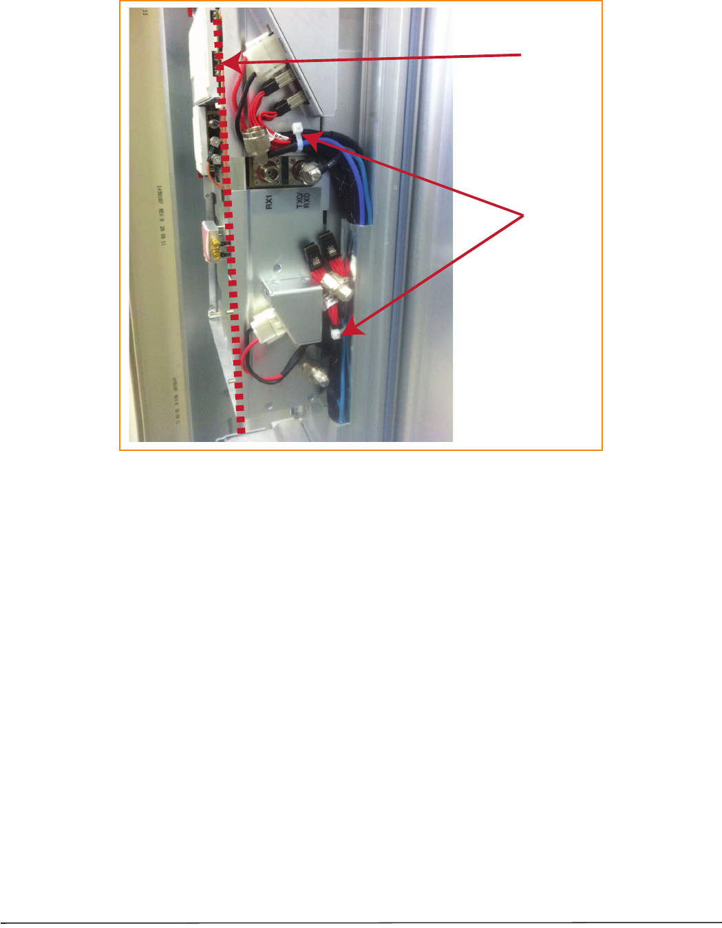
Figure 23. Cable Connections for Dual-Band Dual-Bay RF Modules
Cable ConnecƟons for a Dual-Slot RF Module
Tie wrap
Factory-installed
RX1 cable
Two N-Type
RF connectors
N-Type
RF connector
FlexWave Prism Remote Unit RF Module Installation Guide Page 43
TECP-77-141 Issue 8 • 300001744178 Rev H • September 2015 ©2015 TE Connectivity
Figure 24. Cable Connections for Legacy Dual-Bay 40W RF Modules
CAUTION! Ensure that all cable bends are below the top edge of the Connector Interface Panel as indicated by the
dashed line in the preceding figure. Failure to correctly position the cables could inhibit closing the
Remote Unit door, which can result in damage to the cables.
Tie wrap around
factory-installed
RX1 cable
Keep cable bends
behind the edge
of the Connector
Interface Panel
Page 44 FlexWave Prism Remote Unit RF Module Installation Guide
©2015 TE Connectivity TECP-77-141 Issue 8 • 300001744178 Rev H • September 2015
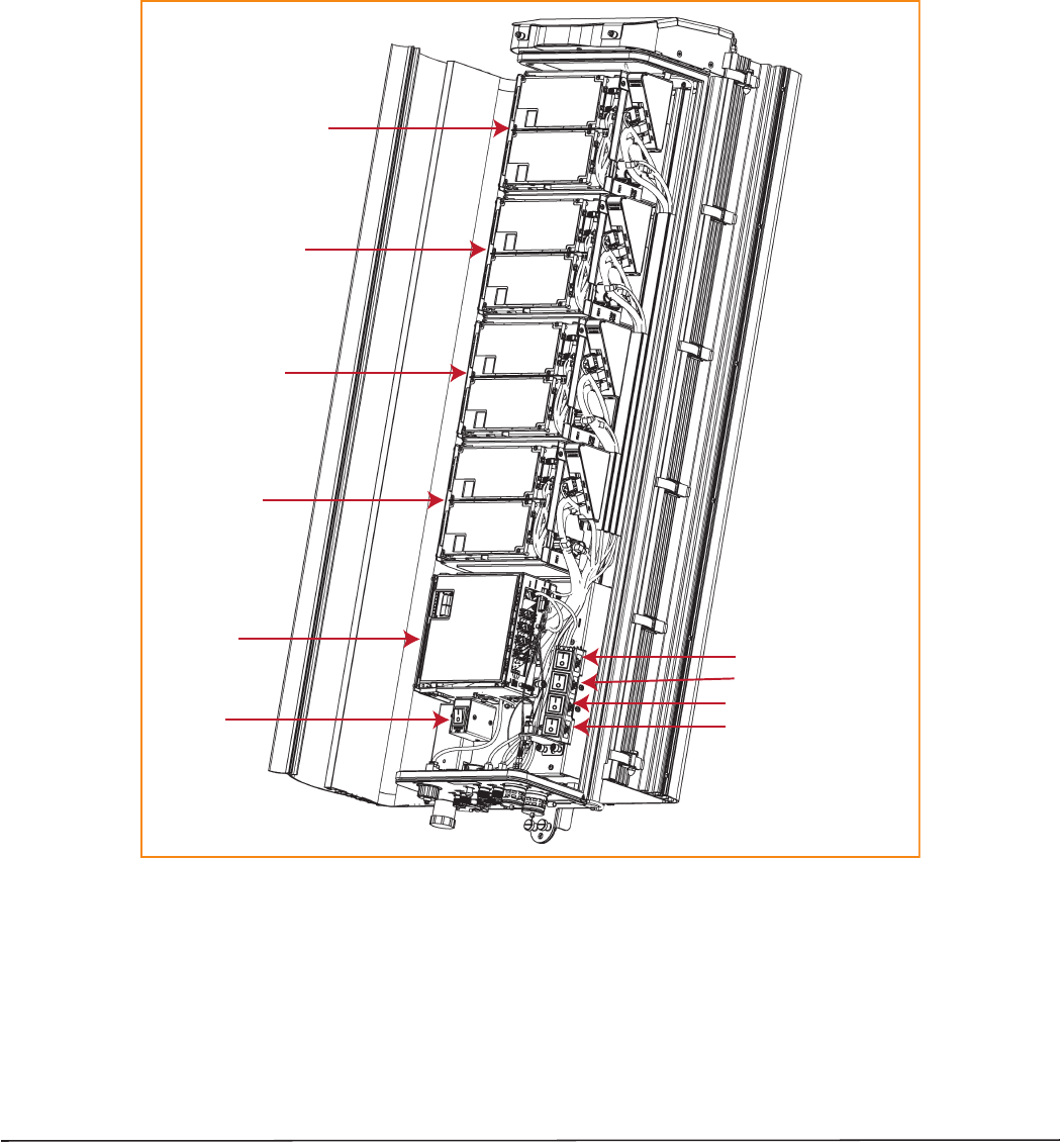
Power on the RF Module(s) and the Prism Remote Unit
1ǡǤ
2Ǥȋǡ
ǢͳǤȌ
NOTE: The preceding graphic illustrates the Status LED on a Quad-Bay PRU. The Status LED for the Single-Bay,
Dual-Bay, and Tri-Bay PRUs is in the same location and functions the same as the Status LED for the
Quad-Bay PRU.
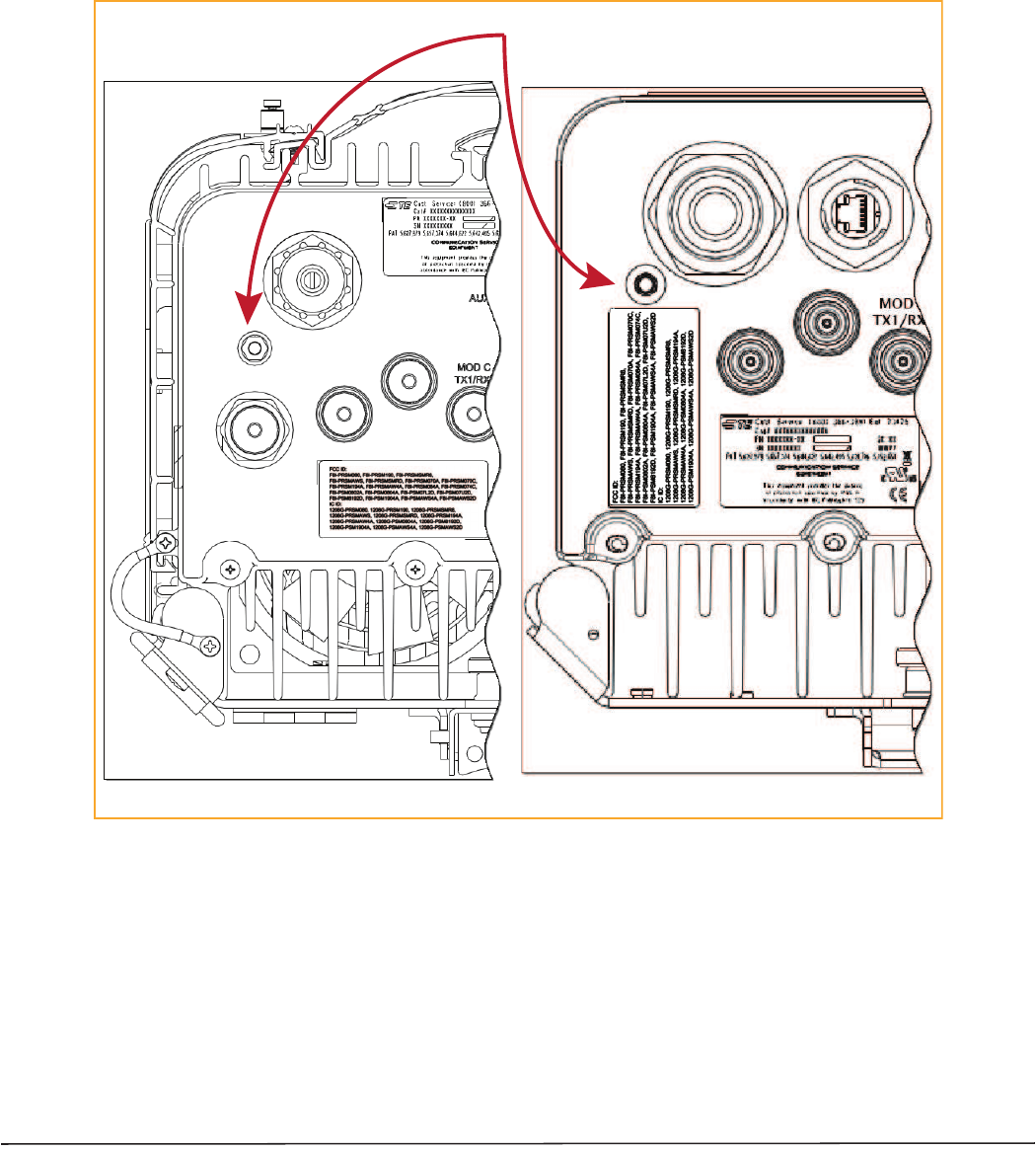
BoƩom of an AC-Powered PRU BoƩom of a DC-Powered PRU
Status LED
NETWORK
POWER
48VDC/XXA
MOD D
TX1/RX1
NETWORK
MOD D
TX1/RX1
POWER
100-240 VAC
50-60 Hz
XX AMPS
WARNING:
HIGH LEAKAGE CURRENT. EARTH
CONNECTION ESSENTIAL BEFORE
CONNECTING SUPPLY
MOD D
TX0/RX0
MOD D
TX0/RX0
FlexWave Prism Remote Unit RF Module Installation Guide Page 45
TECP-77-141 Issue 8 • 300001744178 Rev H • September 2015 ©2015 TE Connectivity
3
Ǥ
•ǦǦǡǤǡ
ǦΪǦǡ
ǢǤ
•ǦͶͲǤǦͶͲ
ΪǡǤ
4ȋȌǤ
ǡ
Ǥǡȋ
DzdzͷʹȌǤ
Bay A
SeRF
Module
AC/DC Power
switch for
PRU chassis
DC Power switch for Bay A
DC Power switch for Bay B
DC Power switch for Bay C
DC Power switch for Bay D
Bay B
Bay C
Bay D
Page 46 FlexWave Prism Remote Unit RF Module Installation Guide
©2015 TE Connectivity TECP-77-141 Issue 8 • 300001744178 Rev H • September 2015
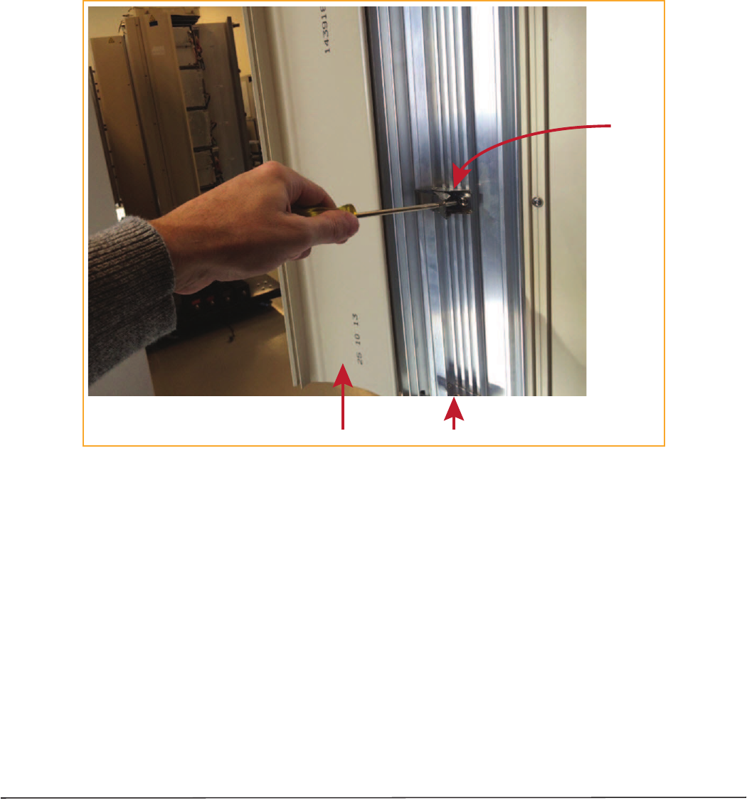
Close the Remote Unit Door and Solar Shield
1ȄǤ
2ȄǤ
ǡǡǦ
Ǥ
3ȄǤ
CAUTION! Service personnel must confirm that the perimeter gasket and door-to-door gaskets are in place when
closing the Remote Unit doors after servicing.
CAUTION! If the PRU door was allowed to snap closed, RF output from an HDM RF Module may be disabled for up
to three minutes. Any alarms generated immediately following the opening/closing of the PRU Doors,
such as Door Open, RF Power Low, System VSWR Fault, and LPA VSWR Fault, automatically clear once
the RF has recovered. If alarms do not clear after three minutes, please contact TE for technical support;
see “Contacting TE Connectivity” on page 52.
Provision the Prism Remote Unit
EMS System Setup and Provisioning Guide
Ǥ
Solar Shield Door
Door latch
FlexWave Prism Remote Unit RF Module Installation Guide Page 47
TECP-77-141 Issue 8 • 300001744178 Rev H • September 2015 ©2015 TE Connectivity
FLEXWAVE NOTCH FILTER (FWP-SPRINTFILTER)
ȋǦȌ
ǣ
•ʹͲͺͲͲȀͳͻͲͲǡȋǦͶͶͳͺͶͳȌ
•ʹͲͺͲͲǡǡȋǦͶͶͲͲͲȌǤ
Notch Filter Installation Tips
ͺͳǤ͵ͷͺͻǤͲǤ
ǣ
•Ǥ
•ǦǤ
•ǡǤ
Ǥ
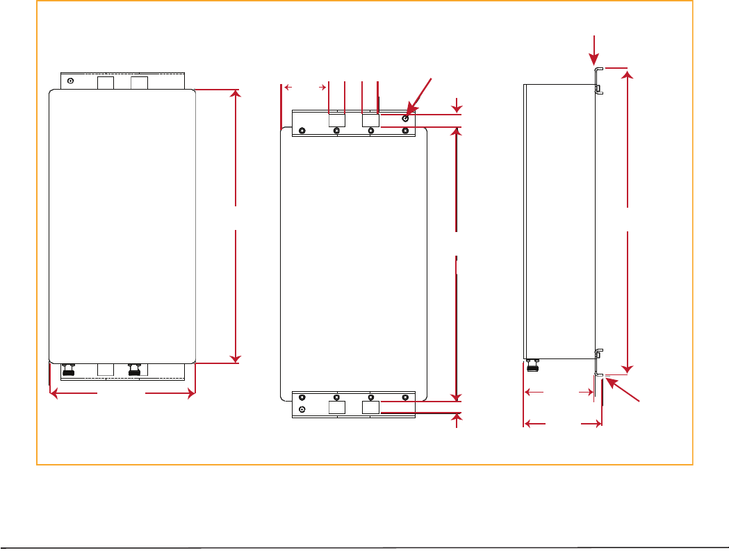
ʹͷǤ
Figure 25. Notch Filter Mounting Dimensions
16.0 ±.1
.70
.70
2.805 .95 .95
1.00
2 LocaƟons
5/16-18
Ground Lug
Front View
Side View
Back View
4.55
17.9 ±.1
4.10 MounƟng
Bracket
15.93
8.51
MounƟng
Bracket
Page 48 FlexWave Prism Remote Unit RF Module Installation Guide
©2015 TE Connectivity TECP-77-141 Issue 8 • 300001744178 Rev H • September 2015
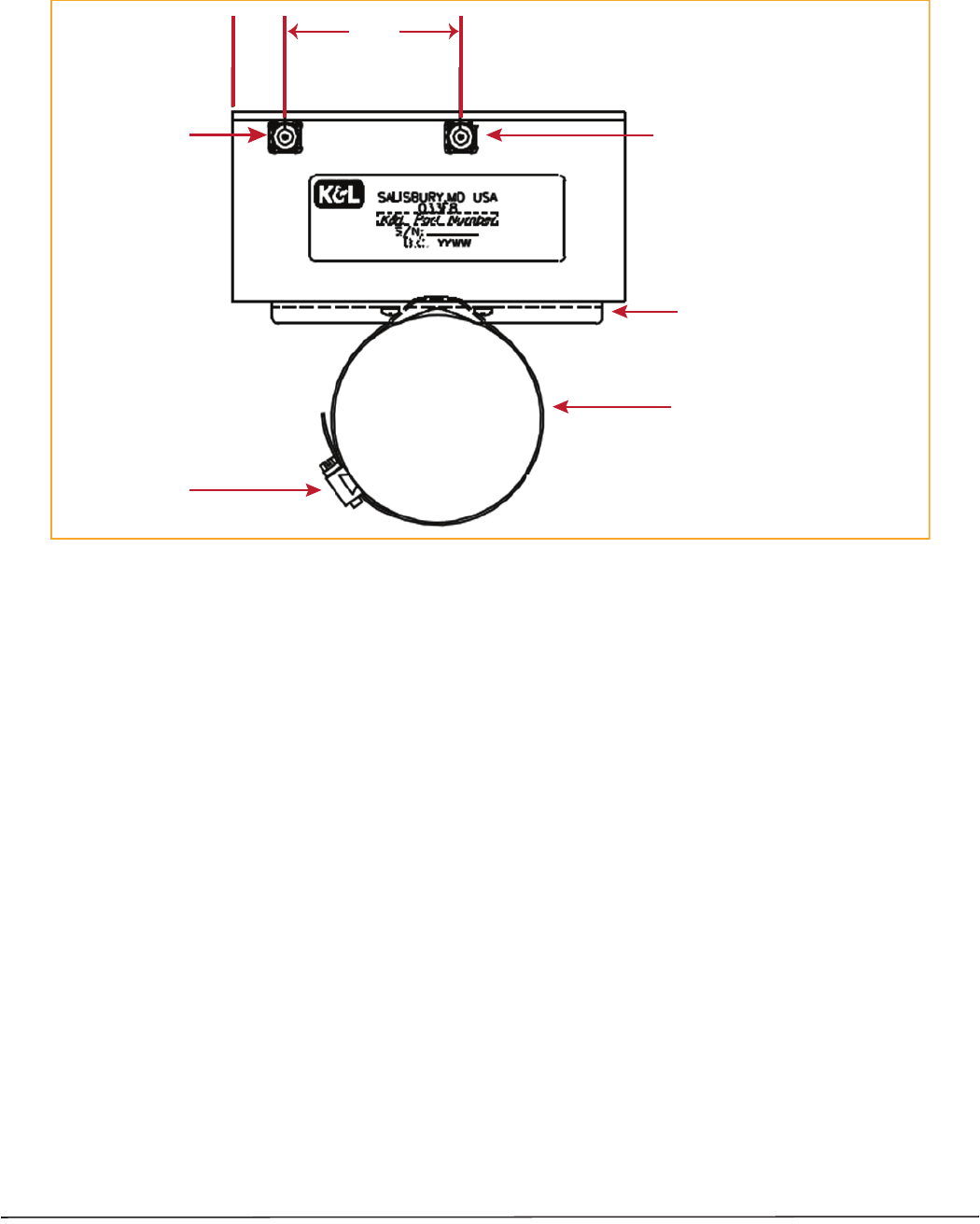
ʹǤ
Figure 26. Pole Mounting a Notch Filter
1.13 3.81
Input
N-Type
Female
Connector
Output
N-Type
Female
Connector
Band must be long enough
to wrap around the pole
BoƩom View of
Notch Filter
Hose clamp sized for
installaƟon requirement
MounƟng Bracket
NOTE: The 800 Notch Filter is
designed to accept input
from the PRU in either its
Output or Input port, as well
as the feed from the antenna.

FlexWave Prism Remote Unit RF Module Installation Guide Page 49
TECP-77-141 Issue 8 • 300001744178 Rev H • September 2015 ©2015 TE Connectivity
Notch Filter Specifications
Frequency Range (MHz) Maximum Emissions (Sprint requirement) per 30 kHz
817-824 —
< 854 < -76 dBm
854-859 < -76 dBm
859-861.35 < -76 dBm
861.35-861.5 < -56 dBm
861.5-861.6 < -42 dBm
862-869 —
Enclosure Rating IP67
RF Connectors N-Type Connector, Female (2)
Ground Studs (w/star washer) All ground Studs must accept AWG 6 wire
Mounting Strap mount (Vertical and Horizontal) on up to 12" pole, or Wall mount
Size 15.93" x 8.51" x 4.10"
Weight 18 LBS
Operational Temperature -25°C to +65°C
Humidity ETSI 300-019-1-3 10%-100% Condensing
Vibration-operation ETSI 300-019-1-4
Vibration-transportation ETSI 300-019-1-2

Page 50 FlexWave Prism Remote Unit RF Module Installation Guide
©2015 TE Connectivity TECP-77-141 Issue 8 • 300001744178 Rev H • September 2015
STANDARDS CERTIFICATION
FCC
ͶͳͷȋȌǡʹʹȋͺͲͲȌǡ
ʹͶȋͳͻͲͲǦȌǡͻͲȋͺͲͲȀͻͲͲǦȌǡʹȋʹͳͲͲǦǡͲͲǦǡʹ͵ͲͲǦǡ
ʹͷͲͲȌǤ
WARNING.Ǥ
ǤǤ
ǡ̈́ͳͲͲǡͲͲͲǤ
IC
Ǧͳ͵ͳǦǤ
DzǣdzǤ
̵Ǥ
ǡ͵ǤͷǡǦ
Ǥ
Ǥ
Note: ȋȌǡ
ͳͲͲͲȋǡȌǡͳͶͲȋ
ȌǡȋʹͲȌ
Ǥ
UL/CUL
ǤͶǡͷͲǡ
Ǥ
ͷʹͻǤ
FDA/CDRH
ͳȀǤ
ʹͳͳͲͶͲǤ
Caution:̵
Ǥ
EU Harmonized Standards
ƬͳͻͻͻȀͷȀǤ
•͵ǤͳȄǡ
ʹͲͲȀͻͷȀǡǤ
•͵ǤͳȄ
ʹͲͲͶȀͳͲͺȀǤ
•͵ǤʹȄǡ
ȀǤ
EMC Standards
ͷͷͲʹʹͷͷͲʹͶȋȌ
Safety Standards
ͲͻͷͲǦͳǡʹΪͳȋȌͲͻͷͲǦͳǡʹΪ
ͳȋͳͶͳȌȋȌ

FlexWave Prism Remote Unit RF Module Installation Guide Page 51
TECP-77-141 Issue 8 • 300001744178 Rev H • September 2015 ©2015 TE Connectivity
ACCESSING USER DOCUMENTATION ON THE TE CUSTOMER PORTAL
ǡǤ
1ǣ
ǣȀȀǤǤȀȀȀ
ȋǡǡENTERǤȌ
2ǤSign Inǡ
ǣ
•ǡAlready Registered? Sign In NowǡEmailPasswordǡ
Sign InǤ
•ǯǡCreate an AccountǡRegister NowǤ
3Wireless Customer PortalǡResourcesDocumentsǡManuals
and Data SheetsǤ
4Manuals and Data Sheetsǡǣ
aǤ
bǤ
cȋȌǤ

Page 52 FlexWave Prism Remote Unit RF Module Installation Guide
©2015 TE Connectivity TECP-77-141 Issue 8 • 300001744178 Rev H • September 2015
CONTACTING TE CONNECTIVITY
Telephone Numbers
Sales
Asia Pacific +65-6294-9948
France 0800 914032
Germany 0180 2232923
Italy 0800 782374
Spain 900 983291
United Kingdom 0800 960236
USA or Canada 1-800-366-3891
Extension 73000
Connectivity Extension 73475
Wireless Extension 73476
Technical Support
USA or Canada 1-800-530-9960
Elsewhere +1-952-917-0761
Online Access
Customer Portal
https://www.te.com/portal/wireless/
Technical Support for Wireless Products
http://www.te.com/WirelessSupport