ADC Telecommunications S2182-011 InterReach Spectrum 800/1900 MHz HP MRAU User Manual 77222p2
ADC Telecommunications Inc. InterReach Spectrum 800/1900 MHz HP MRAU 77222p2
User Manual
TECP-77-222 Issue 2 December 2013
300001759666 Rev B
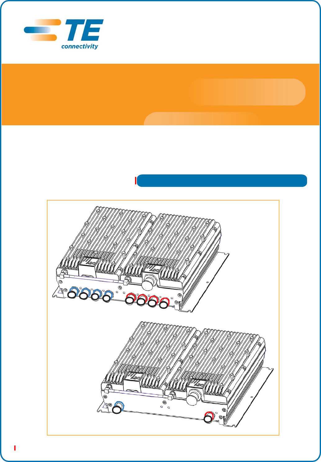
Main Remote Access Unit
Secondary Remote Access Unit
InterReach Spectrum™
Remote Access Unit
Installation Guide
Copyright
© 2013 TE Connectivity, Inc. All Rights Reserved.
Information contained in this document is company private to TE Connectivity Ltd., and
shall not be modified, used, copied, reproduced or disclosed in whole or in part without
the written consent of TE.
Trademark Information
FlexWave, FlexWave Prism, InterReach Spectrum, Universal Radio Head, TE
Connectivity, and TE connectivity (logo) are trademarks.
All other logos, products and/or company names referred to herein might be
trademarks of their respective owners.
Disclaimer of Liability
Contents herein are current as of the date of publication. TE reserves the right to change
the contents without prior notice. Should the content of printed user documentation
shipped with product differ from documentation provided on a product CD (inclusive of
the associated Help modules), the printed user documentation supersedes the
documentation on the product CD. In no event shall TE be liable for any damages
resulting from loss of data, loss of use, or loss of profits, and TE further disclaims any
and all liability for indirect, incidental, special, consequential or other similar damages.
This disclaimer of liability applies to all products, publications and services during and
after the warranty period.
Specific Disclaimer for High-Risk Activities
This Product is not specifically designed, manufactured, tested or intended for use in
high-risk activities including, without restricting the generality of the foregoing, on-line
control of aircraft, air traffic, aircraft navigation or aircraft communications; or in the
design, construction, operation or maintenance of any nuclear facility. TE (including its
affiliates) and its suppliers specifically disclaim any express or implied warranty of
fitness for such purposes or any other purposes.
Screenshots in User Documentation
Due to concurrent development of this documentation, artwork, and the InterReach
Spectrum Element Management System (EMS), there may be some minor discrepancies
between screenshots contained in this documentation and those actually displayed in
the InterReach Spectrum EMS. These discrepancies will generally be few and minor and
should not affect your understanding of InterReach Spectrum EMS.

InterReach Spectrum Remote Access Unit Installation Guide Page 1
TECP-77-222 Issue 2 • 300001759666 Rev B • December 2013 ©2013 TE Connectivity Ltd.
TABLEOFCONTENTS
Preface .................................................................................................................................................................2
RevisionHistory...................................................................................................................................................... 2
DocumentCautionsandNotes .............................................................................................................................. 3
StandardsCertification........................................................................................................................................... 3
ProductOverview.................................................................................................................................................4
MainRemoteAccessUnits..................................................................................................................................... 6
MRAUPorts,Cable,andConnectors ..................................................................................................................................6
MRAULEDs .........................................................................................................................................................................7
SecondaryRemoteAccessUnits ............................................................................................................................ 8
SRAUPorts,Cable,andConnectors....................................................................................................................................8
SRAULEDs...........................................................................................................................................................................9
RAUNConnectors................................................................................................................................................ 10
InstalltheRAUsandAntennas............................................................................................................................11
MounttheRAUsandAntennas............................................................................................................................ 11
ConnecttheIFEUtotheMRAU............................................................................................................................12
ConnecttheMRAUtoSRAUs ............................................................................................................................... 14
ConfiguretheMRAUsandSRAUs......................................................................................................................... 16
AppendixA:Specifications..................................................................................................................................17
RemoteAccessUnitSpecifications ...................................................................................................................... 17
SpectrumSystemSpecifications........................................................................................................................... 17
CompositePowerOutofRAU .............................................................................................................................. 19
AppendixB:75‐OhmCATVCable........................................................................................................................22
CATVCableRequirements.................................................................................................................................... 22
Belden1695ACoaxSpecifications ....................................................................................................................... 23
Description .......................................................................................................................................................................23
OverallPhysicalCharacteristics ........................................................................................................................................23
OverallNominalElectricalCharacteristics........................................................................................................................24
Belden7732ACoaxSpecifications ....................................................................................................................... 25
Description .......................................................................................................................................................................25
OverallPhysicalCharacteristics ........................................................................................................................................25
OverallNominalElectricalCharacteristics........................................................................................................................26
AppendixC:OmniAntenna.................................................................................................................................27
AppendixD:ContactsandUserDocumentation .................................................................................................28
ContactingTEConnectivitybyTelephone............................................................................................................ 28
OnlineAccesstoTEConnectivity ......................................................................................................................... 28
InterReachSpectrumUserDocumentation ......................................................................................................... 28
AccessingUserDocumentationontheTECustomerPortal ................................................................................ 29

Preface
Page 2 InterReach Spectrum Remote Access Unit Installation Guide
© 2013 TE Connectivity Ltd TECP-77-222 Issue 2 • 300001759666 Rev B • December 2013
PREFACE
ThismanualprovidesinstallationinstructionsforInterReachSpectrum®RemoteAccessUnits
(RAUs).Table1liststhestandardRAUsthataresupportedinthisdocument.
RevisionHistory
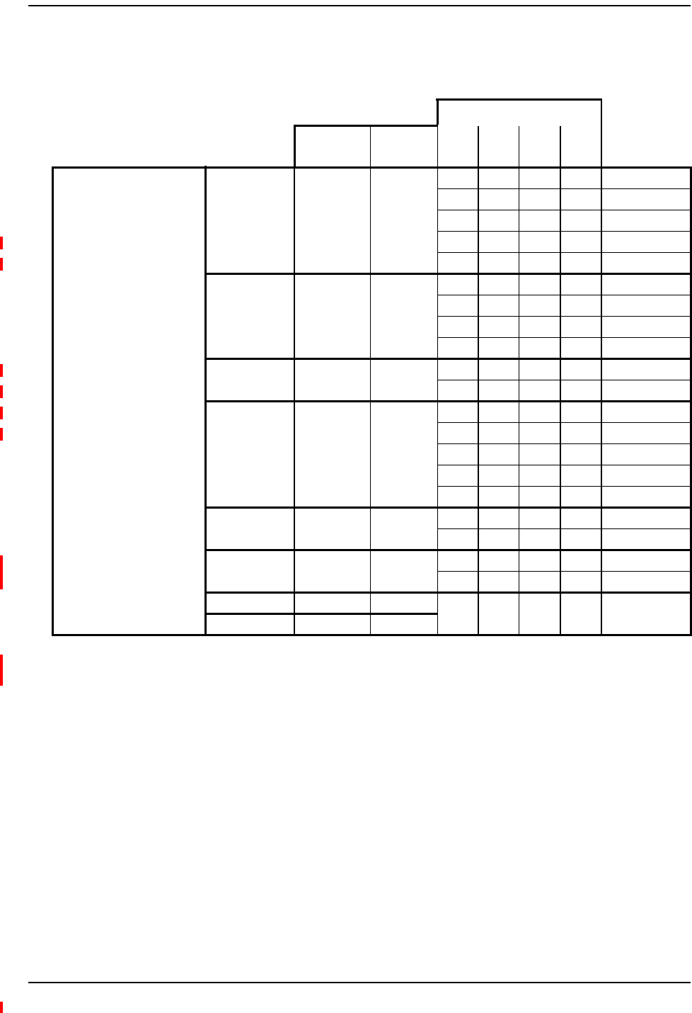
Table1.SupportedSpectrumStandardRemoteAccessUnits
Catalog Number Description
Standard RAUs
SPT-M1-8519-1 Spectrum, 850-1900 Main RAU
SPT-S1-8519-22 Spectrum, 850 Path 2-1900 Path 2 Secondary RAU
SPT-S1-8090-1 Spectrum, 800-900 SMR Secondary RAU
SPT-S1-80AWS-1 Spectrum, 800-2100AWS Path 1 Secondary RAU
SPT-S1-8019-22 Spectrum, 800 Path 2-1900 Path 2 Secondary RAU
SPT-S2-70AWS-1-SISO Spectrum, 700 SISO-2100AWS Path 1 SEC RAU, UpperC-LowerABC
SPT-S2-70AWS-22-SISO Spectrum, 700 Path 2 SISO-2100AWS Path 2 SEC RAU, UpperC-LowerABC
SPT-S1-7070-1-MIMO Spectrum, 700 MIMO Secondary RAU, UpperC-LowerABC
SPT-M1-AWS19-11 Spectrum, 2100AWS Path 1-1900 Path 1 Main RAU
SPT-S1-AWS19-12 Spectrum, 2100AWS Path 1-1900 Path 2 Secondary RAU
SPT-S1-2121-1-MIMO Spectrum, 2100AWS MIMO Secondary RAU
High Power RAUs
SPT-M3-8519-11-HP Spectrum, 850 Path 1-1900 HP Path 1 Main RAU
SPT-S3-2626-12-HP 2600HP Path 1 - 2600HP Path 2 Secondary RAU
SPT-S3-8519-22-HP Spectrum, 850 Path 2 - 1900 HP Path 2 Secondary RAU
SPT-S3-70AWS-11-HP Spectrum, 700 Path 1 uC/LABC-AWS HP Path 1 Secondary RAU
SPT-S3-70AWS-22-HP Spectrum, 700 Path 2 uC/LABC-AWS HP Path 2 Secondary RAU
SPT-M3-8019-31-HP Spectrum, 800 Path 3 - 1900 HP Path 1 Main RAU
Table 2. Revision History
Issue Document Date Technical Updates
1February 2013 Initial release.
2December 2013 •Adds support for the 2600HP Path 1 - 2600HP Path 2 Secondary RAU and the 800 Path 3 - 1900
HP Path 1 Main RAU.
•Updates “Standards Certification” on page 3 and “Appendix C: Omni Antenna” on page 27 with
FCC requirements.
•Adds torque information; see “Connect the IFEU to the MRAU” on page 12 and “Connect the MRAU
to SRAUs” on page 14.

Document Cautions and Notes
InterReach Spectrum Remote Access Unit Installation Guide Page 3
TECP-77-222 Issue 2 • 300001759666 Rev B • December 2013 © 2013 TE Connectivity Ltd.
DocumentCautionsandNotes
Twotypesofmessages,identifiedbelow,appearinthetext:
CAUTION! Cautiontextindicatesoperationsorstepsthatcouldcausepersonalinjury,induceasafety
probleminamanageddevice,destroyorcorruptinformation,orinterruptorstopservices.
NOTE: Notetextcontainsinformationaboutspecialcircumstances.
StandardsCertification
FCC:ThisequipmentcomplieswiththeapplicablesectionsofTitle47CFR,Part22(800MHz
Cellular),Part24(1900MHz‐PCS),Part90(800/900‐SMR),andPart27(700MHz,2100MHz
‐AWS).
WARNING.ThisisNOTaCONSUMERdevice.ItisdesignatedforinstallationbyFCCLICENSEES
andQUALIFIEDINSTALLERS.YouMUSThaveanFCCLICENSEorexpressConsentofanFCC
Licenseetooperatethisdevice.UnauthorizedusemayresultinSignificantforfeiturepenalties,
includingpenaltiesinexcessof$100,000foreachcontinuingviolation.
IC:ThisequipmentcomplieswiththeapplicablesectionsofRSS‐131(800/900–SMR),RSS‐132
(800‐Cellular),andRSS‐133(1900–PCS).Theterm“IC:”beforetheradiocertificationnumber
onlysignifiesthatIndustryCanadaTechnicalSpecificationsweremet.
TheManufacturer'sratedoutputpowerofthisequipmentisforsinglecarrieroperation.For
situationswhenmultiplecarriersignalsarepresent,theratingwouldhavetobereducedby3.5
dB,especiallywheretheoutputsignalisre‐radiatedandcancauseinterferencetoadjacentband
users.Thispowerreductionistobebymeansofinputpowerorgainreductionandnotbyan
attenuatorattheoutputofthedevice.
NOTE: TheU.S.FederalCommunicationsCommission(FCC)hasdevelopedguidelinesforevaluationof
humanexposuretoRFemissions.TheguidelinesincorporatelimitsforMaximumPermissible
Exposure(MPE)forpowerdensityoftransmitteroperatingatfrequenciesbetween300kHzand
100GHz.Limitshavebeensetforportable,mobile,andfixedequipment.TEConnectivity
productsfallinthecategoryoffixedequipment;productsintendedtobepermanentlysecured
andexposuresareevaluatedfordistancesgreaterthan40cm(15.75”).Portabledevicesfallinto
exposuresoflessthan20cm,whereSARevaluationsareused.
Antennagainisrestrictedto1.5WERP(2.49WEIRP)inordertosatisfyRFexposure
compliancerequirements.Ifhigherthan1.5WERP,routineMPEevaluationisneeded.
Theantennasshouldbeinstalledtoprovideatleast40cmfromallpersonstosatisfy
MPErequirementsofFCCPart2,2.1091.
UL/CUL:Thiswillbeinstalledinarestrictedaccesslocation.Thisequipmentcomplies,perUL
andCUL50,StandardforEnclosuresforElectricalEquipment.
UL/CUL:ThisequipmentcomplieswithULandCUL60950‐1StandardforSafetyforInformation
TechnologyEquipment,includingElectricalBusinessEquipment.
UL/CUL:AllInterReachSpectrumRAUsarePlenumratedandsuitableforuseinenvironmental
airspaceinaccordancewithSection300‐22(C)oftheNationalElectricalCode,andSections
2‐128,12‐010(3)and12‐100oftheCanadianElectricalCode,Part1,CSAC22.1.
UL:ThisequipmentisULPlenumratedunderUL2043.
CAUTION! Modificationsnotexpresslyapprovedbythepartyresponsibleforcompliancecouldvoidthe
user'sauthoritytooperatetheequipment.

Product Overview
Page 4 InterReach Spectrum Remote Access Unit Installation Guide
© 2013 TE Connectivity Ltd TECP-77-222 Issue 2 • 300001759666 Rev B • December 2013
PRODUCTOVERVIEW
InterReachSpectrumsupportsupto8bandsinasinglesystem.Eachantennalocationsupports
thosebandsinmodular,grouppairings.EachlocationincludesaMainRemoteAccessUnit
(MRAU)thatcanpoweruptothreeadditionalSecondaryRAUs(SRAUs),eachofwhichsupport
twopoweramplifierpairsforatotalofeightamplifiers.MRAUsandSRAUsaregroupedlogically
basedoncommonserviceprovidergroupingsandinclude:850/1900,700/700MIMO,800/900
SMR,700SISO/AWS,and800/AWS.AddingfrequencyisassimpleasplugginginanSRAUtothe
existingMRAU(seeTable4onpage19throughTable6onpage21in“AppendixA:
Specifications”).
RAUsareavailableintwodifferentoutputpoweroptions:StandardandHighPower.Thesecan
be“mixedandmatched”onasystemtomeetthespecificneedsofavenue.
SinceSpectrumcanbeconfiguredtosupportasmanyasfourcascadedrunsofsixteentotal
ExpansionModuleGroups,thesystemconfigurationpossibilitiesareseeminglyendlessandcan
scaletosinglesystemsthatincludeasmanyas128MRAUlocations,witheachofthoselocations
supportingbetweenoneandeightRFbands.Andeachofthosebandlocationsoffers26dBm
(P1dB)or31dBm(P1dB)ofoutputpowerbasedonselectingstandardorHighPower(HP)RAUs.
ThesystemmaybescaledtoaddnewbandsorRAUlocationsitesas‐neededandoffersgreat
serviceflexibilityandperformancerelativetoshared,wide‐bandamplifiersystems.Eachservice
providermaycontroltheirbandofinterestandenjoythepredictabilityinconsistentserviceat
eachRAUlocationindependentofwhatotheroperatorsaredoingorthelengththesignaltravels
totheservicearea.
TheRAUsaretypicallymountedaboveceilingtilesorinout‐of‐sightlocationsascloseaspossible
totheservicearea.
Standards Certification
InterReach Spectrum Remote Access Unit Installation Guide Page 5
TECP-77-222 Issue 2 • 300001759666 Rev B • December 2013 © 2013 TE Connectivity Ltd.
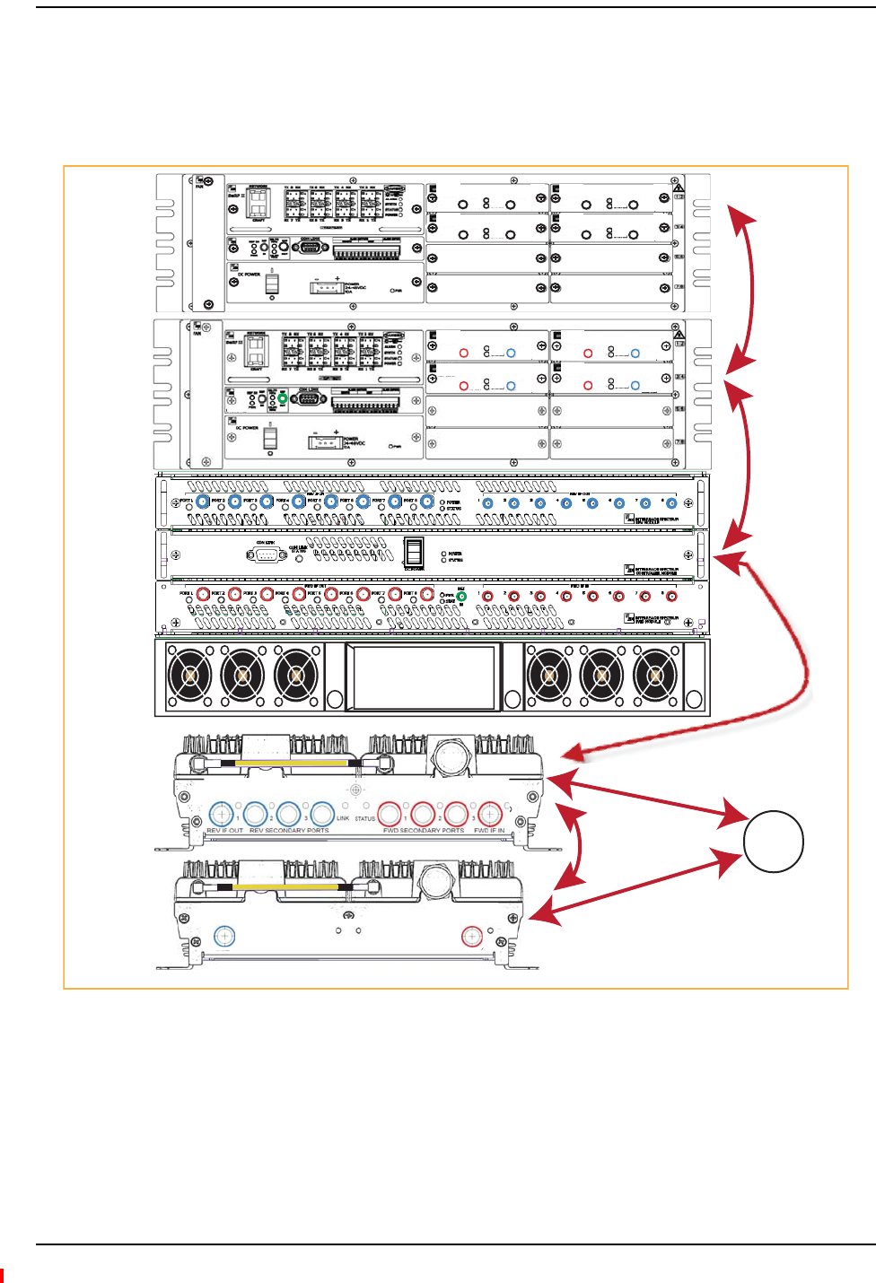
Figure1illustrateshowRFandIFsignalsaresentbetweenSpectrumunitsandmodules.
NOTE: AllFWDportsonallModulesarecolor‐codedredandallREVportsarecolor‐codedblue,which
makestheDRU,IFEU,andRAUcablingprocesseasiertocomplete.
Figure1.REV and FWD Signals for the RAU
NOTE: ThisbookreferstotheOmniAntenna(4214‐0727),whichistheantennathatTEConnectivity
recommends.Otherantennasmaybeused.ForfurtherinformationontheOmniAntenna,see
“AppendixC:OmniAntenna”onpage27.
LINK STATUS
SECONDARY
REV
SECONDARY
FWD
SECONDARY
REV
SECONDARY
FWD
LINK STATUS
REV IF OUT REV SECONDARY PORTS
1 2 3
FWD SECONDARY PORTS
1 2 3
FWD IF IN
LINK STATUS
Host
SRAU
MRAU
Power
Supply
IFEU
DRU
IF
RF
Omni
Antenna
R
F
R
F
x
x x
xx
x x
xx
x x
xx
x
x x
xx
x x
xx
x x
xx
x
REMOTE
SYSTEM II
IF DART
XXXXXXXXXX
BW XX MHz
FWD
IF OUT
REV
IF IN
PWR
STATUS
REMOTE
IF DART
XXXXXXXXXX
BW XX MHz
FWD
IF OUT
REV
IF IN
PWR
STATUS
REMOTE
IF DART
XXXXXXXXXX
BW XX MHz
FWD
IF OUT
REV
IF IN
PWR
STATUS
REMOTE
IF DART
XXXXXXXXXX
BW XX MHz
FWD
IF OUT
REV
IF IN
PWR
STATUS
REMOTE
IF
IF
HOST
SYSTEM II
RF DART
SMR900
FWD 935-940
REV 896-901
REV
RF OUT
FWD
RF IN
FWD NOT TO
EXCEED +5 dBm
PWR
STATUS
HOST
RF DART
SMR900
FWD 935-940
REV 896-901
REV
RF OUT
FWD
RF IN
FWD NOT TO
EXCEED +5 dBm
PWR
STATUS
HOST
RF DART
SMR900
FWD 935-940
REV 896-901
REV
RF OUT
FWD
RF IN
FWD NOT TO
EXCEED +5 dBm
PWR
STATUS
HOST
RF DART
SMR900
FWD 935-940
REV 896-901
REV
RF OUT
FWD
RF IN
FWD NOT TO
EXCEED +5 dBm
PWR
STATUS
HOST
NOTE: Units shown are not to scale.
Product Overview
Page 6 InterReach Spectrum Remote Access Unit Installation Guide
© 2013 TE Connectivity Ltd TECP-77-222 Issue 2 • 300001759666 Rev B • December 2013
MainRemoteAccessUnits
TheMainRemoteAccessUnit(MRAU)receivesFWDIFsignalsfromanIFExpansionUnit(IFEU),
whichispartoftheSpectrumExpansionModuleGroup,using75CATVcable.TheMRAU
convertstheIFsignalstoRFandsendsthemtoapassiveRFantennausing50coaxialcable.The
MRAUalsoreceivesconfigurationinformationandpowerfromandsendsitsstatusinformation
totheIFEU.
TheMRAUreceivesREVRFsignalsfromapassiveRFantennausing50coaxialcable.Itconverts
thesignalstoIFandsendsthemtotheIFEUusing75CATVcable.
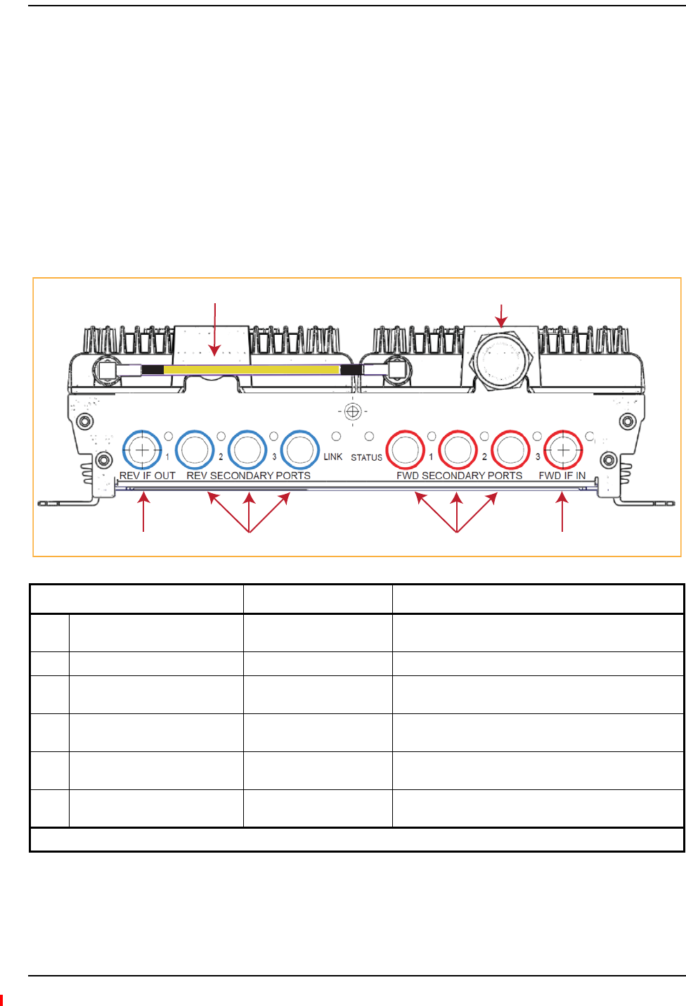
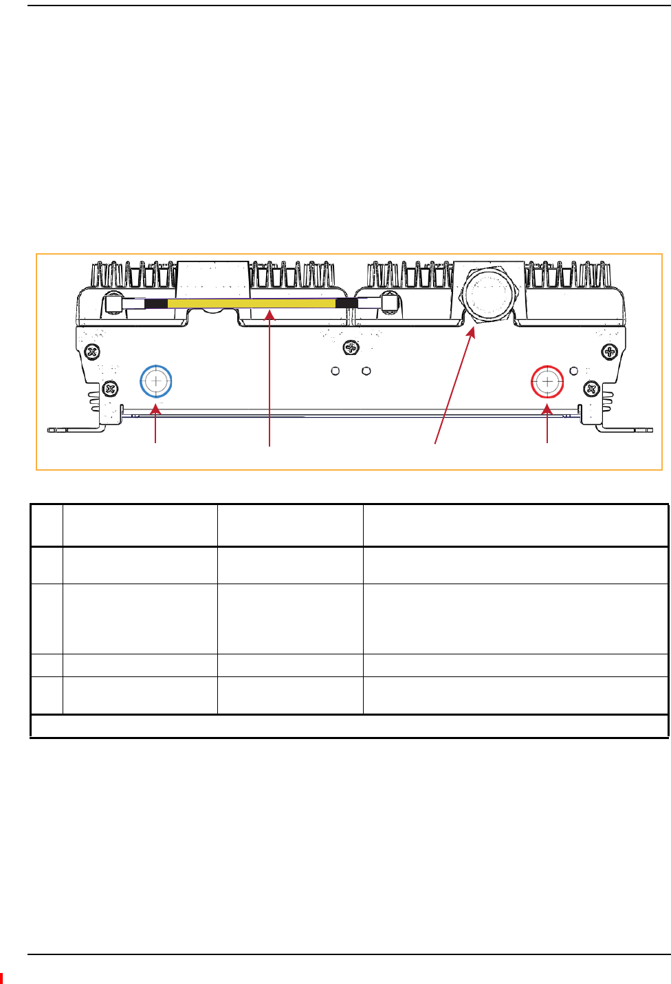
MRAUPorts,Cable,andConnectors
Ref # Component Device Function
1RF SubMiniature version A
(SMA) cable (1)
50 RF SMA-to-SMA cable Connects two RF bands together when there is only one
N-type connector on the RAU.
2Antenna port(s) 50 N-type connector Connects to an antenna. See Table 3 on page 10.
3FWD IF IN connector F connector port Connects to the IFEU FWD Module IF OUT connector via
CATV cable.
4FWD SECONDARY PORTS (1 - 3) F connector ports Connect to a SRAU SECONDARY FWD connector via
CATV cable.
5REV SECONDARY PORTS (1 - 3) F connector ports Connect to a SRAU SECONDARY REV connector via
CATV cable.
6REV IF OUT connector F connector port Connects to the IFEU REV Module IF IN connector via
CATV cable.
(1) The AWS/PCS MRAUs do NOT have an RF SMA cable—they have two Antenna ports.
REV IF OUT REV SECONDARY PORTS
1 2 3
FWD SECONDARY PORTS
1 2 3
FWD IF IN
LINK STATUS
1 2
36 54
Main Remote Access Units
InterReach Spectrum Remote Access Unit Installation Guide Page 7
TECP-77-222 Issue 2 • 300001759666 Rev B • December 2013 © 2013 TE Connectivity Ltd.
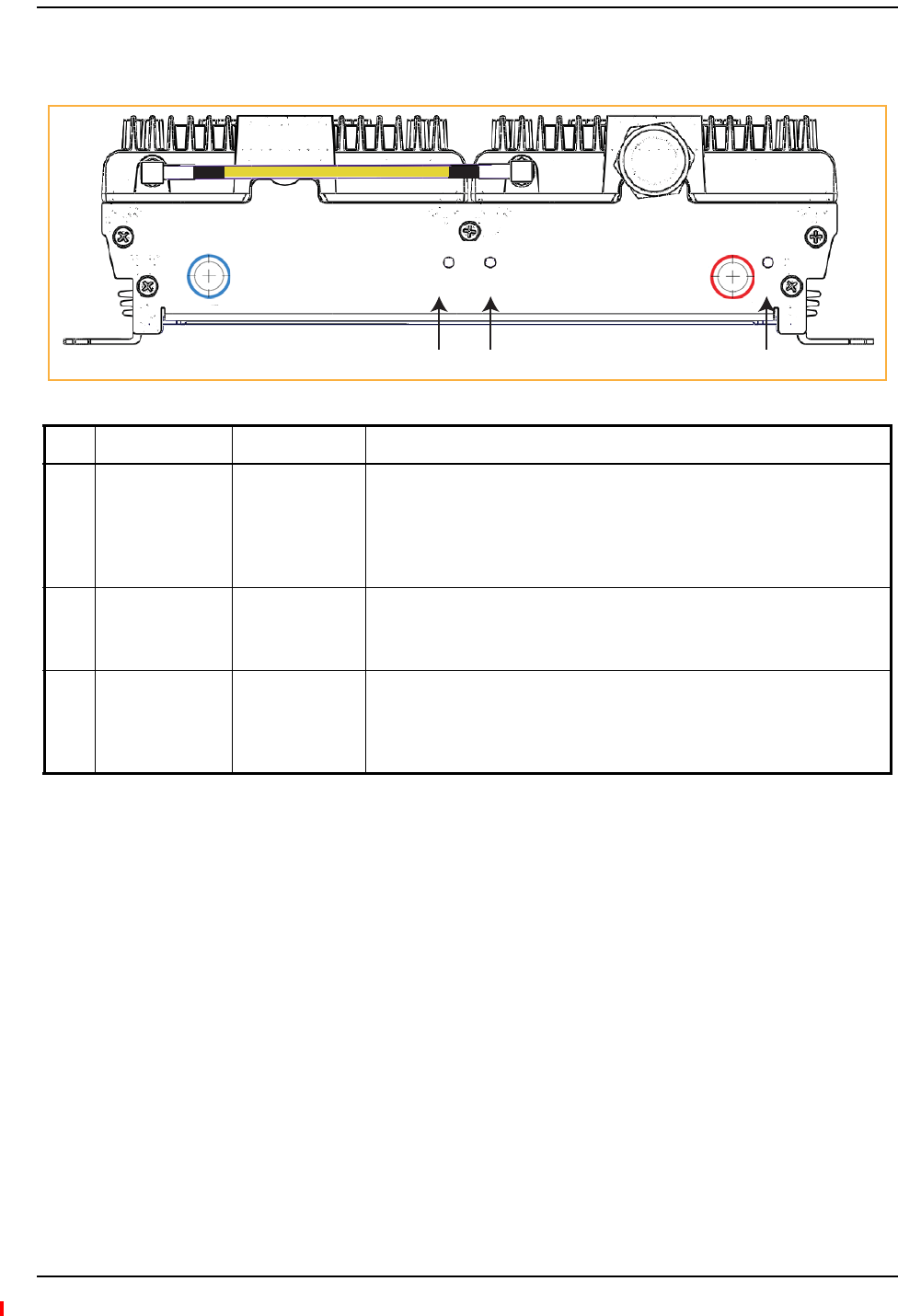
MRAULEDs
Ref # LED LED Color Description
1FWD SECONDARY PORT
(1 - 3)
• Green • Downstream unit correctly connected; unit has no alarms or a
Minor alarm is active.
• Blinking Green • SRAU or band is set out-of-service.
• Yellow • FWD cable connected to SRAU, no REV cable connected.
• Blinking yellow • FWD and REV cables are not connected to the same port number
(incorrectly paired).
• Red • Major alarm in downstream unit, fault lockout, or SRAU
disconnected.
• Off • No SRAU previously connected.
2LINK
•Green •MRAU receiving communications from the IFEU.
• Red • MRAU has not received communications from the IFEU for more
than 90 seconds.
• Off • During initial power up, MRAU is powering up and waiting for IFEU
communications.
3STATUS
• Green • Unit has no alarms or a Minor alarm is active.
• Blinking green • Unit or band is set out-of-service.
• Red • Major alarm detected.
4REV SECONDARY PORT
(1 - 3)
• Green • Downstream unit correctly connected, unit has no alarms or minor
alarm
• Blinking Green • SRAU or band is set out-of-service.
• Blinking Yellow • FWD and REV cables are not connected to the same port number
(incorrectly paired).
• Red • Major alarm in downstream unit, fault lockout, or SRAU
disconnected.
• Off • No SRAU previously connected.
5FWD IF IN
• Green • MRAU is powered on correctly.
•Yellow or
Blinking Yellow
• There is an IFEU FWD connection, but there is no IFEU REV
connection or the IFEU REV connection is paired incorrectly.
• Off • Cable is not connected to the IFEU FWD port.
REV IF OUT REV SECONDARY PORTS
1 2 3
FWD SECONDARY PORTS
1 2 3
FWD IF IN
LINK STATUS
415
2 3
Product Overview
Page 8 InterReach Spectrum Remote Access Unit Installation Guide
© 2013 TE Connectivity Ltd TECP-77-222 Issue 2 • 300001759666 Rev B • December 2013
SecondaryRemoteAccessUnits
ASecondaryRemoteAccessUnit(SRAU)receivesFWDIFsignalsfromtheMRAU,using75
CATVcable.TheSRAUconvertstheIFsignalstoRFandsendsthemtoapassiveRFantennausing
50coaxialcable.TheSRAU,throughtheMRAU,alsoreceivesconfigurationinformationand
powerfromandsendsitsstatusinformationtotheIFEU.
TheSRAUreceivesREVRFsignalsfromapassiveRFantennausing50coaxialcable.Itconverts
thesignalstoIFandsendsthemtotheMRAUusing75CATVcable.
SRAUPorts,Cable,andConnectors
Ref
#
Component Device Function
1SECONDARY REV connector F connector port Connects to one of the MRAU REV SECONDARY ports (1 - 3)
via CATV cable.
2RF SMA cable (1)
50 RF SMA-to-SMA cable
Connects two RF bands together when there is only one
N-type connector on the RAU.
For cases when there is an N-type connector for each RF band
(700MIMO or PCS/AWS), there will not be an SMA cable.
3Antenna port(s) 50 N-type connector Connects to an antenna. See Table 3 on page 10.
4SECONDARY FWD connector F connector port Connects to one of the MRAU FWD SECONDARY ports (1 - 3)
via CATV cable.
(1) The 700 MIMO SRAU does NOT have an RF SMA cable; it has two Antenna ports.
142
3
LINK STATUS
SECONDARY
REV
SECONDARY
FWD
SECONDARY
REV
SECONDARY
FWD
LINK STATUS
Secondary Remote Access Units
InterReach Spectrum Remote Access Unit Installation Guide Page 9
TECP-77-222 Issue 2 • 300001759666 Rev B • December 2013 © 2013 TE Connectivity Ltd.
SRAULEDs
Ref # LED LED Color Description
1 LINK
•Green •SRAU receiving communications from the IFEU.
• Red • SRAU has not received communications from the IFEU for more than 90
seconds.
• Off • During initial power up, SRAU is powering up and waiting for IFEU
communications.
2STATUS
• Green • Unit has no alarms or a Minor alarm is active.
• Blinking Green • Unit or band is set out-of-service.
• Red • Major alarm detected.
3SECONDARY FWD
• Green • SRAU is powered on correctly.
•Yellow or
Blinking Yellow
• There is an MRAU FWD connection, but there is no MRAU REV connection
or the MRAU REV connection is paired incorrectly.
• Off • Cable is not connected to the MRAU FWD port.
LINK STATUS
SECONDARY
REV
SECONDARY
FWD
SECONDARY
REV
SECONDARY
FWD
LINK STATUS
312

Product Overview
Page 10 InterReach Spectrum Remote Access Unit Installation Guide
© 2013 TE Connectivity Ltd TECP-77-222 Issue 2 • 300001759666 Rev B • December 2013
RAUNConnectors
EachRAUalsohasoneortwo50‐N‐typeconnectorsthatconnecttoapassiveantenna.Table3
liststhenumberofN‐typeconnectorsavailableoneachRAUmodel.
Table3.NumberofNConnectorsonRAUs
Catalog Number Description Number of RF
N Connectors*
Standard RAUs
SPT-M1-8519-1 Spectrum, 850-1900 Main RAU 1
SPT-M1-AWS19-11 Spectrum, 2100AWS Path 1-1900 Path 1 Main RAU 2
SPT-S1-2121-1-MIMO Spectrum, 2100AWS MIMO Secondary RAU 2
SPT-S1-7070-1-MIMO Spectrum, 700 MIMO Secondary RAU, UpperC-LowerABC 2
SPT-S1-8019-22 Spectrum, 800 Path 2-1900 Path 2 Secondary RAU 1
SPT-S1-8090-1 Spectrum, 800-900 Path 1 SMR Secondary RAU 1
SPT-S1-80AWS-1 Spectrum, 800-2100AWS Path 1 Secondary RAU 1
SPT-S1-8519-22 Spectrum, 850 Path 2-1900 Path 2 Secondary RAU 1
SPT-S1-AWS19-12 Spectrum, 2100AWS Path 1-1900 Path 2 Secondary RAU 2
SPT-S2-70AWS-1-SISO Spectrum, 700 SISO-2100AWS Path 1 SEC RAU, UpperC-LowerABC 1
SPT-S2-70AWS-22-SISO Spectrum, 700 Path 2 SISO-2100AWS Path 2 SEC RAU, UpperC-LowerABC 1
High Power RAUs
SPT-M3-8519-11-HP Spectrum, 850 Path 1-1900 HP Path 1 Main RAU 1
SPT-S3-2626-12-HP 2600HP Path 1 - 2600HP Path 2 Secondary RAU 2
SPT-S3-8519-22-HP Spectrum, 850 Path 2 - 1900 HP Path 2 Secondary RAU 1
SPT-S3-70AWS-11-HP Spectrum, 700 Path 1 uC/LABC-AWS HP Path 1 Secondary RAU 1
SPT-S3-70AWS-22-HP Spectrum, 700 Path 2 uC/LABC-AWS HP Path 2 Secondary RAU 1
SPT-M3-8019-31-HP Spectrum, 800 Path 3 - 1900 HP Path 1 Main RAU 1
* There are two bands per RAU, which results in two N connectors. When there is one N connector, the two bands are
combined internally and both bands use the single N connector.

Mount the RAUs and Antennas
InterReach Spectrum Remote Access Unit Installation Guide Page 11
TECP-77-222 Issue 2 • 300001759666 Rev B • December 2013 © 2013 TE Connectivity Ltd.
INSTALLTHERAUSANDANTENNAS
FollowthestepsintheorderprovidedtoinstalltheRAUsandantennas.
MounttheRAUsandAntennas
CAUTION! Wetconditionsincreasethepotentialforreceivinganelectricalshockwheninstallingorusing
electricallypoweredequipment.Topreventelectricalshock,neverinstalloruseelectrical
equipmentinawetlocationorduringalightningstorm.
CAUTION! ThissystemisaRFTransmitterandcontinuouslyemitsRFenergy.Maintainaminimum8‐inch
(20cm)clearancefromtheantennawhilethesystemisoperating.Wheneverpossible,shut
downtheRANbeforeservicingtheantenna.
NOTE: RAUsaresuitableforuseinenvironmentalairspaceinaccordancewithSection300‐22(c)ofthe
NationalElectricalCode,andSections2‐128,12‐010(3)and12‐100oftheCanadianElectrical
Code,Part1,CSAC22.1.
CAUTION! InstallRAUsinindoorlocationsonly.Donotconnectanantennainstalledinanoutdoorlocation
toaRAU,unlessitisinanapprovedAOCweatherproofNEMA4housing.
CAUTION! AttachallRAUssecurelytoastationaryobject(thatis,awall,pole,orceilingbrackets).Tomount
aRAUsecurelytoawall,ceilingbracket,orpole,use#6diameterfastenersinthefourslotted
mountingholes.
CAUTION! Dothefollowingtomaintainproperventilation:
•Keepatleast76mm(3‐inch)clearancearoundtheRAU.
•DonotstackRAUsontopofeachother.
•AlwaysmounttheRAUwiththesolidface(containingthemountingholes)againstthe
mountingsurface.
NOTE: YoucanplacetheRAU,withoutitsfasteninghardware,onaflatsurface,suchasashelf,desk,
cabinet,oranyotherhorizontalsurfacethatallowsstableplacement,withthemountingbase
facingdowntothemountingsurface.
CAUTION! IfinstallingtheRAUonaflatsurface,thesurfacemustbeabletoholdaminimum7‐poundload
securely.
Install the RAUs and Antennas
Page 12 InterReach Spectrum Remote Access Unit Installation Guide
© 2013 TE Connectivity Ltd TECP-77-222 Issue 2 • 300001759666 Rev B • December 2013
Dothefollowing,intheorderpresented,tomounttheRAUsandantennas:
1MountallMRAUandSRAUsinthelocationsmarkedonthefloorplans.
2Installthepassiveantennasaccordingtothemanufacturer’sinstallationinstructions.
NOTE: Itiscommonpracticetoinstallpassiveantennasbelowtheceiling.Ifyouinstallapassive
antennaabovetheceiling,whenestimatingtheantennacoveragearea,accountforadditional
lossduetotheceilingmaterial.
3Connectapassivemulti‐bandantennatotheNconnectoroneachRAUusingcoaxialcable
withtheleastamountoflosspossible.(See“AppendixC:OmniAntenna”onpage27for
informationontheOmniAntennaports.)
CAUTION! Firmlyhand‐tightentheNconnector.DONOTover‐tightentheconnector.
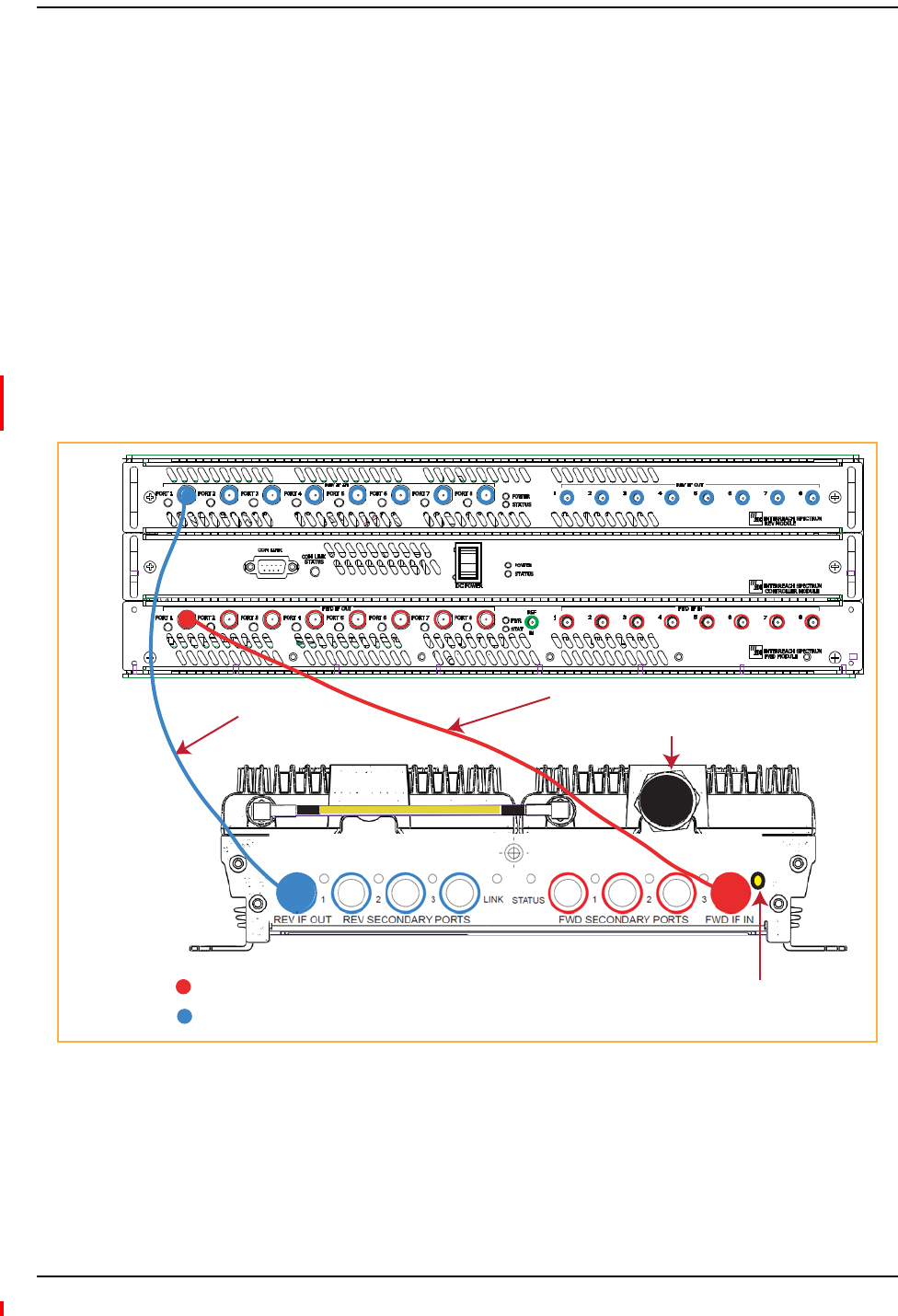
ConnecttheIFEUtotheMRAU
NOTE: TheIFEUshouldbepoweredupbeforestartingthisprocedure;seetheInterReachSpectrum
ExpansionModuleGroupInstallationGuide(TECP‐77‐167).
4FollowtheserulesfortheCATVcableswhenconnectingtheIFEUtotheMRAU:
•TheFWDandREVcablesshouldbeclosetothesamelength.
•TheFWDandREVcablesshouldbethesamecabletype(bothRG6orbothRG11).
•ApairofCATVcablesconnectseachMRAUtotheIFEU.TheIFEUREVModuleIFINport
andtheIFEUFWDModuleIFOUTportmustmatch.Forexample,ifIFEUREVModuleIF
INPort3isused,useIFEUFWDModuleIFOUTPort3.
•Referto“AppendixB:75‐OhmCATVCable”onpage22forinformationonmaximumRG‐6
orRG‐11CATVcablelengths.
5TestthecableterminationforeachCATVcablebeforeinstallingit.
Omni Antenna
False Ceiling
SRAU N1
REV IF OUT REV SECONDARY PORTS
1 2 3
FWD SECONDARY PORTS
1 2 3
FWD IF IN
LINK STATUS
LINK STATUS
SECONDARY
REV
SECONDARY
FWD
MRAU N1
Coaxial cable
Coaxial cable
Connect the IFEU to the MRAU
InterReach Spectrum Remote Access Unit Installation Guide Page 13
TECP-77-222 Issue 2 • 300001759666 Rev B • December 2013 © 2013 TE Connectivity Ltd.
6ConnectFconnectorCATVcablesontheIFEUandMRAU,intheordergivenbelow.
IftheLEDsdonotperformasdescribedinthisprocedure,referto“MRAULEDs”onpage7.
aConnectaCATVcablefromoneoftheIFEUFWDModuleIFOUTconnectors(1‐8)tothe
MRAUFWDIFINconnector.
bConfirmthattheMRAUFWDIFINLEDisyellow,whichindicatesacorrectphysical
connection.
cConnectaCATVcablefromtheIFEUREVModuleIFINconnector(1‐8)totheMRAUREV
IFOUTconnector,makingsurethatyoupairtheportusedtothesameportnumber
selectedinStep6a.
Iftheconnectioniscorrect,theMRAUpowersupandtheMRAUFWDIFINLEDturns
green.
NOTE: TorqueappliedtotheFconnectorCATVcablesshouldbe7±5%in‐lbs.
Step 6a
IFEU
REV IF OUT REV SECONDARY PORTS
1 2 3
FWD SECONDARY PORTS
1 2 3
FWD IF IN
LINK STATUS
MRAU
To an antenna
Step 6c
KEY: IFEU FWD Module IF OUT connector to MRAU FWD IF IN connector
IFEU REV Module IF IN connector to MRAU REV IF OUT connector
Step 6b

Install the RAUs and Antennas
Page 14 InterReach Spectrum Remote Access Unit Installation Guide
© 2013 TE Connectivity Ltd TECP-77-222 Issue 2 • 300001759666 Rev B • December 2013
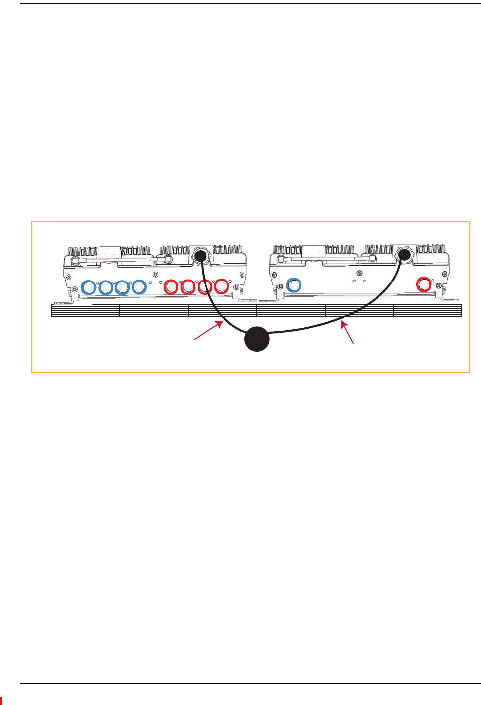
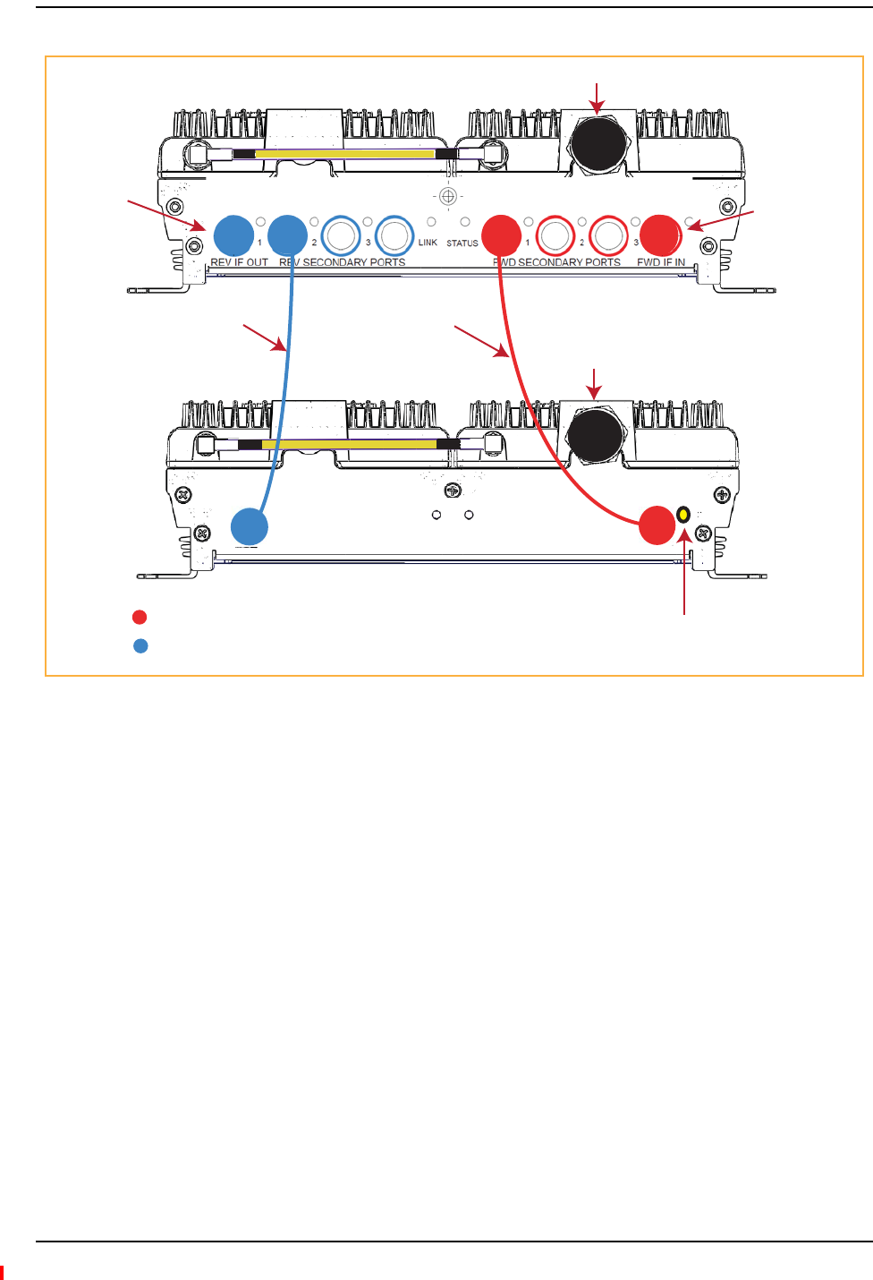
ConnecttheMRAUtoSRAUs
CAUTION! Topreventinterference,donotinstallan850/1900MRAUantennanearan800/900SRAU.The
850MHzbandmustbe20feetawayfromthe800/1900SRAU’spassiveantenna.
7Useoneofthefollowing6’and20’CATVRG6jumpers,availableforpurchasefromTE
Connectivity,toconnectanMRAUtoSRAUs.
8TestthecableterminationforeachCATVcablebeforeinstallingit.
9ConnectFconnectorCATVcablesfromtheMRAUtoanSRAU,intheordergivenbelow.Ifthe
LEDsdonotperformasdescribedinthisprocedure,referto“SRAULEDs”onpage9.
aConnectaCATVcablefromanMRAUFWDSECONDARYPORT(1,2,or3)Fconnectorto
theSRAUSECONDARYFWDFconnector.
bConfirmthattheSRAUSECONDARYFWDLEDisyellow,whichindicatesacorrect
physicalconnection.
cConnectaCATVcablefromanMRAUREVSECONDARYPORT(1,2,or3)Fconnectorto
theSRAUSECONDARYREVFconnector,matchingthesameportnumberselectedinStep
9a.Thatis,ifinStep9ayouconnectedanFconnectortotheMRAUFWDSECONDARY
PORT1,thepairedCATVcablemustconnecttotheMRAUREVSECONDARYPORT1.
Iftheconnectioniscorrect,theSRAUpowersupandtheSRAUSECONDARYFWDLED
turnsgreen.
NOTE: TorqueappliedtotheFconnectorCATVcablesshouldbe7±5%in‐lbs.
TE Connectivity
Part Number
Description Note
300469-0 6’ RG-6 Cable; F Male to F Male CATV cable that connects the MRAU to SRAUs. Two
cables required per SRAU.
300469-1 20’ RG-6 Cable; F Male to F Male CATV cable that connects the MRAU to SRAUs. Two
cables required per SRAU.
Connect the MRAU to SRAUs
InterReach Spectrum Remote Access Unit Installation Guide Page 15
TECP-77-222 Issue 2 • 300001759666 Rev B • December 2013 © 2013 TE Connectivity Ltd.
MRAU
REV IF OUT REV SECONDARY PORTS
1 2 3
FWD SECONDARY PORTS
1 2 3
FWD IF IN
LINK STATUS
KEY: MRAU FWD Secondary port to SRAU Secondary FWD port
MRAU REV Secondary port to SRAU Secondary REV port
LINK STATUS
SECONDARY
REV
SECONDARY
FWD
SECONDARY
REV
SECONDARY
FWD
LINK STATUS
SRAU
To an antenna
To an antenna
To an IFEU
REV Module
IF IN connector
(1 - 8)
To an IFEU
FWD Module
IF OUT connector
(1 - 8)
Step 9a
Step 9b
Step 9c
Install the RAUs and Antennas
Page 16 InterReach Spectrum Remote Access Unit Installation Guide
© 2013 TE Connectivity Ltd TECP-77-222 Issue 2 • 300001759666 Rev B • December 2013
10 RepeatStep9toinstalluptotwomoreSRAUs,aspersystemdesign.
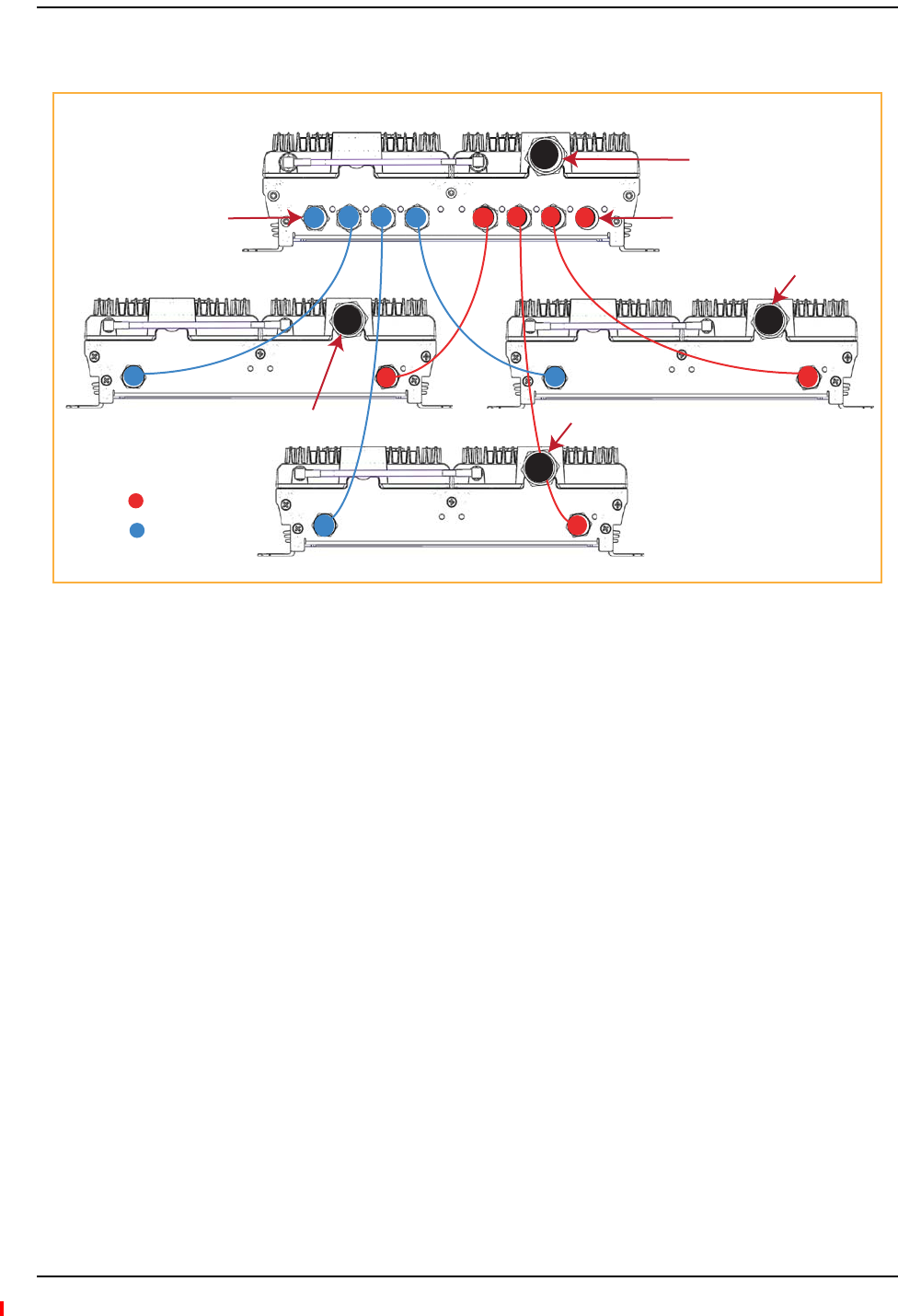
ConfiguretheMRAUsandSRAUs
RefertotheInterReachSpectrum™ElementManagementSystem7.3UserManual(TECP‐77‐200)
forinformationonhowtoconfiguretheMRAUsandSRAUs.
REV IF OUT REV SECONDARY PORTS
1 2 3
FWD SECONDARY PORTS
1 2 3
FWD IF IN
LINK STATUS
LINK STATUS
SECONDARY
REV
SECONDARY
FWD
LINK STATUS
SECONDARY
REV
SECONDARY
FWD
LINK STATUS
SECONDARY
REV
SECONDARY
FWD
MRAU
SRAU1
SRAU2
SRAU3
To an IFEU FWD Module
IF OUT connector (1 - 8)
To an IFEU REV Module
IF IN connector (1 - 8)
To an antenna
To an antenna
To an antenna
To an antenna
KEY: FWD
REV

Remote Access Unit Specifications
InterReach Spectrum Remote Access Unit Installation Guide Page 17
TECP-77-222 Issue 2 • 300001759666 Rev B • December 2013 © 2013 TE Connectivity Ltd.
APPENDIXA:SPECIFICATIONS
RemoteAccessUnitSpecifications
OperatingTemp ‐25°Cto+50°C
StorageTemperature ‐40°Cto+70°C
Humidity 10%to95%non‐condensing
Dimensions 11.50"x9.00"x3.50"
Weight 7.49Pounds
PowerSource +54Vdc(fromIFEU)
SpectrumSystemSpecifications
RFSpecification
SupportedFrequencyBlocks 2perRemoteAntennaUnit;1‐8perHostUnit
Bandwidth 1.5to75MHznon‐contiguous
PropagationDelay
SystemDelay <12microseconds
DelayManagementDigital (ManualorAutomatic)
Appendix A: Specifications
Page 18 InterReach Spectrum Remote Access Unit Installation Guide
© 2013 TE Connectivity Ltd TECP-77-222 Issue 2 • 300001759666 Rev B • December 2013
NominalPassbandBandwidthsandGains
FrequencyBandsSupported 850Cellular;800iDEN;900iDEN;1900PCS;2100AWS;
2600LTE;700UpperC/LowerABC
RF Frequency
TX RX
850 Cell
Bandwidth 869-894 824-849
Gain (dB) 40 30
800 SMR
Bandwidth 851-869 806-824
Gain (dB) 40 30
900 SMR
Bandwidth 935-940 896-901
Gain (dB) 40 30
1900 PCS
Bandwidth 1930-1995 1850-1915
Gain (dB) 40 30
2600 LTE
Bandwidth 2620-2690 2500-2570
Gain (dB) 40 30
700 Upper C
Bandwidth 746-756 776-786
Gain (dB) 40 30
700 Lower ABC
Bandwidth 728-746 698-716
Gain (dB) 40 30
Low/Medium Power
Level
700-900 MHz
Typical
Low/Medium Power
Level
1900-2600 MHz
Typical
High
Power Level
1900-2600 MHz
Typical3
TX RX TX RX TX RX
Average gain with 180 m CATV
at 25°C (77° F) (dB)
401/43230 401/43230 48 30
Ripple with 180 m CATV (dB) 2.5 3.0 3.5 4.0 3.5 4.0
Output IP3 (dBm) 38 38 43
Input IP3 (dBm) -8 -8 -8
Output 1 dB Compression Point (dBm) 26 26 31
Noise Figure 1 HU-1 EMG-8 RAUs (dB) 17 17 17
Noise Figure 1 HU-4 EMG-32 RAUs (dB) 23 23 23
1Low Power is defined here as a Standard MRAU used with
Standard SRAUs; see Table 4 on page 19.
2Medium Power is defined here as a High Power MRAU used
with Standard SRAUs; see Table 5 on page 20.
3High Power is used to define a High Power MRAU used with
High Power SRAUs; see Table 6 on page 21.
Composite Power Out of RAU
InterReach Spectrum Remote Access Unit Installation Guide Page 19
TECP-77-222 Issue 2 • 300001759666 Rev B • December 2013 © 2013 TE Connectivity Ltd.
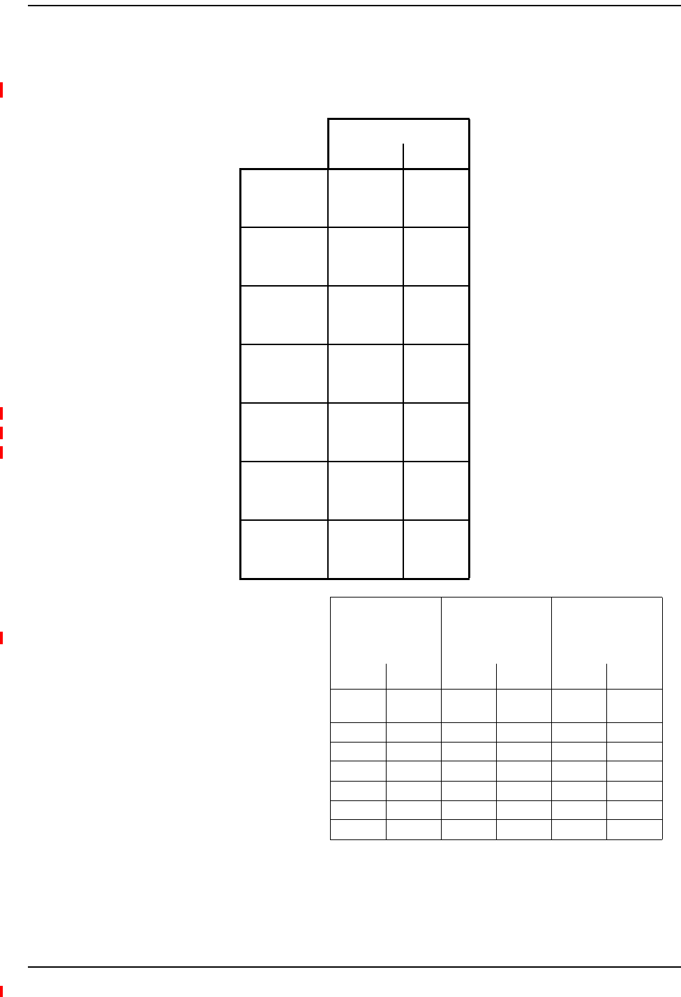
CompositePowerOutofRAU
Table4.LowPowerLevel:StandardMRAUwithSRAUs
Power per Carrier (dBm) per
Band
RF Frequency Number of RF Carriers
TX RX 1
P-out
2
P-out
4
P-Out
8
P-out
Standard MRAUs:
850 Cell 869-894 824-849
26.0 20.0 14.0 9.0 GSM
•SPT-M1-8519-1 23.0 17.5 12.0 8.0 EDGE
•SPT-M1-AWS19-11 15.0 12.0 9.0 6.0 CDMA
15.0 12.0 9.0 6.0 WCDMA
Standard SRAUs 15.0 12.0 9.0 6.0 LTE
•SPT-S1-8090-1
800 SMR 851-869 806-824
17.5 14.0 10.0 6.5 iDEN
•SPT-S1-7070-1-MIMO 26.0 19.5 13.5 8.5 APCO 25 C4FM
•SPT-S1-80AWS-1 15.0 12.0 9.0 6.0 CDMA
•SPT-S2-70AWS-1-SISO 15.0 12.0 9.0 6.0 LTE
•SPT-S2-70AWS-22-SISO 900 SMR 935-940 896-901 17.5 14.0 10.0 6.5 iDEN
•SPT-S1-AWS19-12 26.0 20.0 13.5 9.0 APCO 25 C4FM
•SPT-S1-2121-1-MIMO
1900 PCS 1930-1995 1850-1915
26.0 20.0 14.0 9.0 GSM
•SPT-S1-8019-22 23.0 17.5 12.0 8.0 EDGE
•SPT-S1-8519-22 15.0 12.0 9.0 6.0 CDMA
15.0 12.0 9.0 6.0 WCDMA
15.0 12.0 9.0 6.0 LTE
2100 AWS 2110-2155 1710-1755 15.0 12.0 9.0 6.0 WCDMA
15.0 12.0 9.0 6.0 LTE
700 Upper C 746-756 776-786 15.0 12.0 9.0 6.0 LTE
700 Lower ABC 728-746 698-716

Appendix A: Specifications
Page 20 InterReach Spectrum Remote Access Unit Installation Guide
© 2013 TE Connectivity Ltd TECP-77-222 Issue 2 • 300001759666 Rev B • December 2013
1 SeepowerpercarrierofHPMRAUfromTable6onpage21.
Table5.MediumPowerLevel:HighPowerMRAUs1usedwithStandardSRAUs
Power per Carrier (dBm) per
Band
RF Frequency Number of RF Carriers
TX RX 1
P-out
2
P-out
4
P-Out
8
P-out
850 Cell 869-894 824-849
26.0 20.0 14.0 9.0 GSM
23.0 17.5 12.0 8.0 EDGE
18.0 15.0 12.0 9.0 CDMA
18.0 15.0 12.0 9.0 WCDMA
Standard SRAUs 18.0 15.0 12.0 9.0 LTE
•SPT-S1-8090-1
800 SMR 851-869 806-824
17.5 14.0 10.0 6.5 iDEN
•SPT-S1-7070-1-MIMO 26.0 19.5 13.5 8.5 APCO 25 C4FM
•SPT-S1-80AWS-1 18.0 15.0 12.0 9.0 CDMA
•SPT-S2-70AWS-1-SISO 18.0 15.0 12.0 9.0 LTE
•SPT-S2-70AWS-22-SISO 900 SMR 935-940 896-901 17.5 14.0 10.0 6.5 iDEN
•SPT-S1-AWS19-12 26.0 19.5 13.5 8.5 APCO 25 C4FM
•SPT-S1-2121-1-MIMO
1900 PCS 1930-1995 1850-1915
26.0 20.0 14.0 9.0 GSM
•SPT-S1-8019-22 23.0 17.5 12.0 8.0 EDGE
•SPT-S1-8519-22 18.0 15.0 12.0 9.0 CDMA
18.0 15.0 12.0 9.0 WCDMA
18.0 15.0 12.0 9.0 LTE
2100 AWS 2110-2155 1710-1755 18.0 15.0 12.0 9.0 WCDMA
18.0 15.0 12.0 9.0 LTE
700 Upper C 746-756 776-786 18.0 15.0 12.0 9.0 LTE
700 Lower ABC 728-746 698-716
Composite Power Out of RAU
InterReach Spectrum Remote Access Unit Installation Guide Page 21
TECP-77-222 Issue 2 • 300001759666 Rev B • December 2013 © 2013 TE Connectivity Ltd.
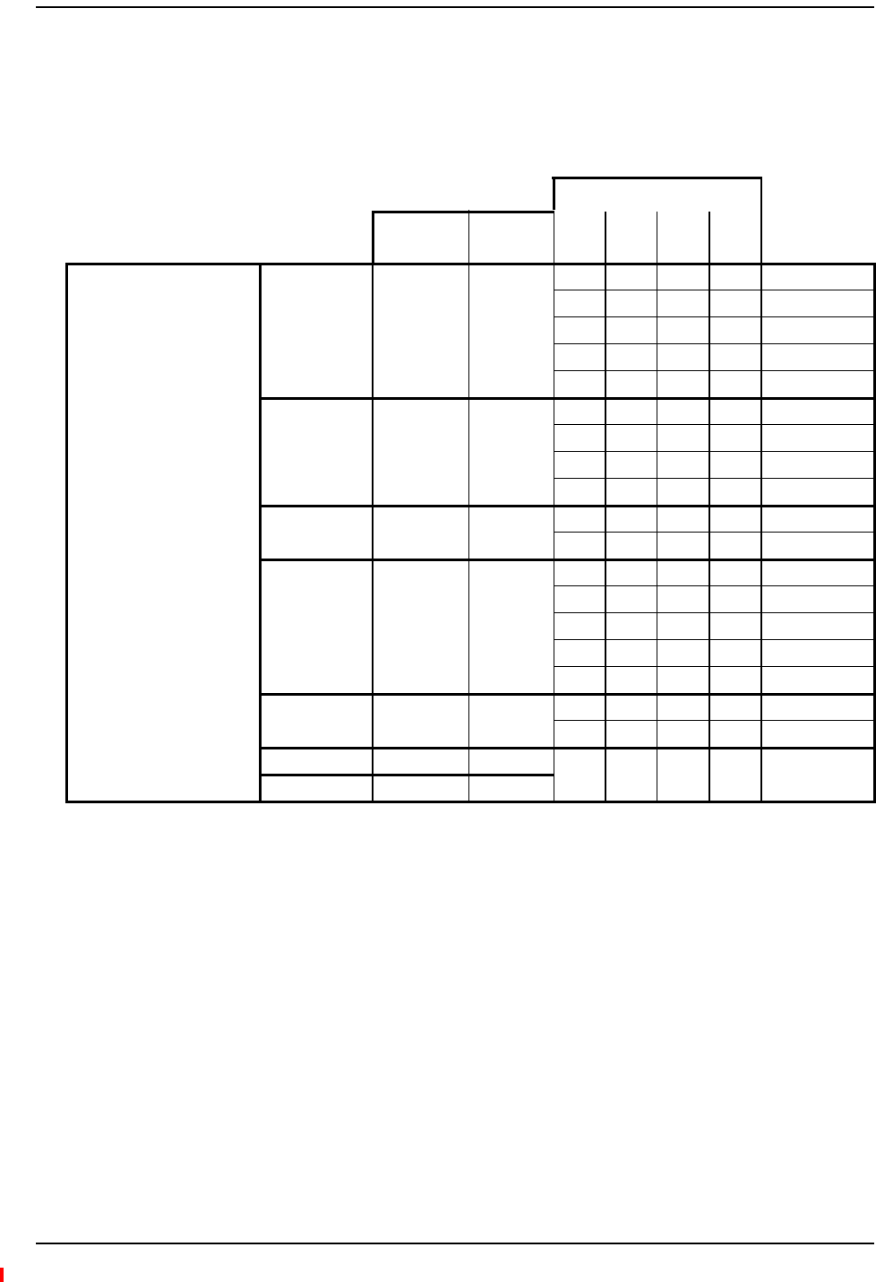
NOTE: Model:SPT‐M3‐8019‐31‐HP‐IndustryCanadaMeanOutputPoweris24.33dBm(800SMR)and
26.83dBm(1900PCS).
Table6.HighPowerLevel:HighPowerMRAUwithHighPowerSRAUs
Power per Carrier (dBm) per
Band
RF Frequency Number of RF Carriers
TX RX 1
P-out
2
P-out
4
P-Out
8
P-out
850 Cell 869-894 824-849
26.0 20.0 14.0 9.0 GSM
High Power MRAU 23.0 17.5 12.0 8.0 EDGE
•SPT-M3-8519-11-HP 18.0 15.0 12.0 9.0 CDMA
•SPT-M3-8019-31-HP 18.0 15.0 12.0 9.0 WCDMA
18.0 15.0 12.0 9.0 LTE
High Power SRAUs
800 SMR 851-869 806-824
17.5 14.0 10.0 6.5 iDEN
•SPT-S3-70AWS-11-HP 26.0 19.5 13.5 8.5 APCO 25 C4FM
•SPT-S3-70AWS-22-HP 18.0 15.0 12.0 9.0 CDMA
•SPT-S3-8519-22-HP 18.0 15.0 12.0 9.0 LTE
•SPT-S3-2626-12-HP 900 SMR 935-940 896-901 17.5 14.0 10.0 6.5 iDEN
26.0 19.5 13.5 8.5 APCO 25 C4FM
1900 PCS 1930-1995 1850-1915
26.0 23.0 19.0 14.0 GSM
26.0 22.5 17.0 13.0 EDGE
23.0 20.0 17.0 14.0 CDMA
23.0 20.0 17.0 14.0 WCDMA
23.0 20.0 17.0 14.0 LTE
2100 AWS 2110-2155 1710-1755 23.0 20.0 17.0 14.0 WCDMA
23.0 20.0 17.0 14.0 LTE
2600 LTE 2620-2690 2500-2570 23.0 20.0 17.0 14.0 WCDMA
23.0 20.0 17.0 14.0 LTE
700 Upper C 746-756 776-786 18.0 15.0 12.0 9.0 LTE
700 Lower ABC 728-746 698-716
Appendix B: 75-Ohm CATV Cable
Page 22 InterReach Spectrum Remote Access Unit Installation Guide
© 2013 TE Connectivity Ltd TECP-77-222 Issue 2 • 300001759666 Rev B • December 2013
APPENDIXB:75‐OHMCATVCABLE
The75‐OhmCATVCable:
•connectstheIFEUtoMRAU(s)andtheMRAU(s)totheSRAU(s)
•transmits(FWD)multibandandreceives(REV)IFsignals
•deliversDCelectricalpowertotheRAUs.TheSpectrumIFEUDCvoltageoutputis+54Vdc
nominal.IftheIFEUreachesitscurrentlimit,acurrent‐limitingcircuitprotectsit.
•carriesconfigurationandstatusinformation
•uses75type‐Fconnectorswithcaptivecenterpins.
CATVCableRequirements
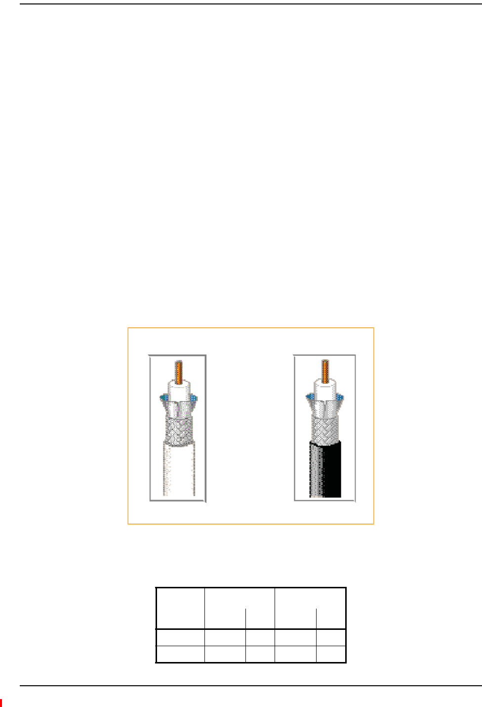
BeldenCATVcableorequivalentisrequired(seeFigure2).
•FortheRG‐6cable,useaBelden1695ACoax.
•FortheRG‐11cable,useaBelden7732ACoax.
NOTE: TEConnectivityrequiressolidcoppercenterconductorCATVcableforproperDCvoltagetothe
RAUandmaximumdistances.
Figure2.Belden 1695A and 7732A Coax Cables
•UseRG‐6orRG‐11CATVcablebetweentheIFEUandMRAU,thetypicallengthsofwhichare
listedbelow.
Cable Type
Minimum Length Maximum Length
Meters Feet Meters Feet
RG-6 0 0 125 410
RG-11 0 0 180 590
RG-11
Belden 1695A Coax
RG-6
Belden 7732A Coax

Belden 1695A Coax Specifications
InterReach Spectrum Remote Access Unit Installation Guide Page 23
TECP-77-222 Issue 2 • 300001759666 Rev B • December 2013 © 2013 TE Connectivity Ltd.
•UseonlyRG‐6CATVcablebetweentheMRAUandSRAU,thelengthsofwhicharelistedbelow.
Belden1695ACoaxSpecifications
Description
RG‐6/Utype,18AWGsolid0.040‐inchbarecopperconductor,plenum,foamFluorinatedEthylene
Propylene(FEP)insulation,Duofoil®+tinnedcopperbraidshield(95%coverage),Flamarrest®
jacket.
OverallPhysicalCharacteristics
Conductor OneCoax
18AWG
Solidstranding
BareCopper(BC)conductormaterial
0.040‐inchdiameter
Insulation Teflon®
FoamFluorinatedEthylenePropylene(FFEP)
0.170‐inchdiameter
OuterShieldLayer1Duofoil
®
Tape
AluminumFoil‐PolyesterTape‐AluminumFoil
100%coverage
OuterShieldLayer2Braid
TinnedCopper(TC)
95%coverage
OuterJacket Flamarrest®
LowSmokePolyvinylChloride(LSPVC)
OverallCabling 0.234‐inchoverallnominaldiameter
RG-6 Cable Meters Feet
Typical 26.56
800/900 iDEN to 850 CELL 619.68
800 AWS to 850 CELL 619.68

Appendix B: 75-Ohm CATV Cable
Page 24 InterReach Spectrum Remote Access Unit Installation Guide
© 2013 TE Connectivity Ltd TECP-77-222 Issue 2 • 300001759666 Rev B • December 2013
OverallNominalElectricalCharacteristics
CharacteristicImpedance 75.000
Inductance 0.103H/ft.
CapacitanceConductortoShield 16.100(pF/ft.)
VelocityofPropagation 82(%)
Delay 1.240(ns/ft.)
ConductorDCResistance 6.400@20°C(/1000ft.)
OuterShieldDCResistance 2.800@20°C(/1000ft.)
Attenuation
Freq. (MHz) Attenuation (dB/100 ft.)
1.000 0.240
3.580 0.450
5.000 0.550
7.000 0.650
10.000 0.750
67.500 1.740
71.500 1.780
88.500 1.940
100.000 2.100
135.000 2.400
143.000 2.500
180.000 2.800
270.000 3.400
360.000 4.000
540.000 5.200
720.000 6.100
750.000 6.200
1000.000 7.300
1500.000 9.200
2000.000 10.900
2250.000 11.600
3000.000 13.700

Belden 7732A Coax Specifications
InterReach Spectrum Remote Access Unit Installation Guide Page 25
TECP-77-222 Issue 2 • 300001759666 Rev B • December 2013 © 2013 TE Connectivity Ltd.
Belden7732ACoaxSpecifications
Description
RG‐11/Utype,14AWGsolid0.064‐inchbarecopperconductor,plenum,foamFEPinsulation,
Duofoil®+tinnedcopperbraidshield(95%coverage),fluorocopolymerjacket.
OverallPhysicalCharacteristics
Conductor OneCoax
18AWG
Solidstranding
BareCopper(BC)conductormaterial
0.064‐inchdiameter
Insulation Teflon®
FoamFluorinatedEthylenePropylene(FFEP)
0.274‐inchdiameter
OuterShieldLayer1Duofoil
®
Tape
AluminumFoil‐PolyesterTape‐AluminumFoil
100%coverage
OuterShieldLayer2Braid
TinnedCopper(TC)
95%coverage
OuterJacket Fluorocopolymer(PVDF)
OverallCabling 0.348‐inchoverallnominaldiameter

Appendix B: 75-Ohm CATV Cable
Page 26 InterReach Spectrum Remote Access Unit Installation Guide
© 2013 TE Connectivity Ltd TECP-77-222 Issue 2 • 300001759666 Rev B • December 2013
OverallNominalElectricalCharacteristics
CharacteristicImpedance 75.000
Inductance 0.091H/ft.
CapacitanceConductortoShield 16.300(pF/ft.)
VelocityofPropagation 83(%)
Delay 1.220(ns/ft.)
ConductorDCResistance 2.500@20°C(/1000ft.)
OuterShieldDCResistance 1.600@20°C(/1000ft.)
Attenuation
Freq. (MHz) Attenuation (dB/100 ft.)
1.000 0.150
3.580 0.260
5.000 0.300
7.000 0.340
10.000 0.400
67.500 1.200
71.500 1.240
88.500 1.400
100.000 1.500
135.000 1.780
143.000 1.840
180.000 2.090
270.000 2.600
360.000 3.100
540.000 3.890
720.000 4.570
750.000 4.680
1000.000 5.500
1500.000 6.910
2000.000 8.130
2250.000 9.200
3000.000 10.200

Belden 7732A Coax Specifications
InterReach Spectrum Remote Access Unit Installation Guide Page 27
TECP-77-222 Issue 2 • 300001759666 Rev B • December 2013 © 2013 TE Connectivity Ltd.
APPENDIXC:OMNIANTENNA
TheOmniAntenna(4214‐0727),showninFigure3,isaroundradomewiththefollowing
specifications:
Figure3.Omni Antenna
NOTE: TwoantennasperRAUisrequiredforMIMOperformance.
WARNING! Maximumgainantennaallowedis3dBi
Port 1 Port 2 Port 3
Gain, typical 2 dBi @ 698-960 MHz 2 dBi @ 698-960 MHz 3 dBi @1710-2170 MHz
3 dBi @ 1710-2170 MHz 3 dBi @ 1710-2170 MHz 3 dBi @ 2496-2690 MHz
Nominal impedance 50 Ohm
Polarization Vertical
VSWR < 2:1
Port-to-port isolation >15 dB min, 22 dB typical
Power rating 5 Watt
Mechanical
Dimension of Antenna (DxH) 215 x 72 mm
Weight Less than or equal to 1.65 lbs (0.75kg), including pigtails
Connector N (male)
Cable (pigtail) length 6 feet, plenum rated cable
Color White, UV protected plastic for outdoor use
Mounting hardware Screws, anchor, and butterfly nut for ceiling tile mount
Environmental
Operating temperature - 40°C to + 65°C
Shipping and Handling ISTA Procedure 1A
Ingress protection IP-42
Flammability UL94V0 (Materials)
Compliance ROHS compliant
Ceiling mount, vertically polarized, omni directional antenna

Appendix D: Contacts and User Documentation
Page 28 InterReach Spectrum Remote Access Unit Installation Guide
© 2013 TE Connectivity Ltd TECP-77-222 Issue 2 • 300001759666 Rev B • December 2013
APPENDIXD:CONTACTSANDUSERDOCUMENTATION
ContactingTEConnectivitybyTelephone
OnlineAccesstoTEConnectivity
InterReachSpectrumUserDocumentation
TheInterReachSpectrumuserdocumentationisintendedforsystemadministrators,engineers
andinstallersresponsibleforplanning,administering,configuring,andmaintainingTE
ConnectivityInterReachSpectrumsystems.Table7onpage29liststhemanualsthatcorrespond
tothisInterReachSpectrumrelease.
Sales
Asia Pacific +65-6294-9948
France 0800 914032
Germany 0180 2232923
Italy 0800 782374
Spain 900 983291
United Kingdom 0800 960236
USA or Canada 1-800-366-3891
Extension 73000
Connectivity Extension 73475
Wireless Extension 73476
Technical Support
USA or Canada 1-800-530-9960
Elsewhere +1-952-917-0761
Customer Portal
https://www.te.com/commerce/uso/myaccount.do
Technical Support for Wireless Products
http://www.te.com/WirelessSupport
Accessing User Documentation on the TE Customer Portal
InterReach Spectrum Remote Access Unit Installation Guide Page 29
TECP-77-222 Issue 2 • 300001759666 Rev B • December 2013 © 2013 TE Connectivity Ltd.
AccessingUserDocumentationontheTECustomerPortal
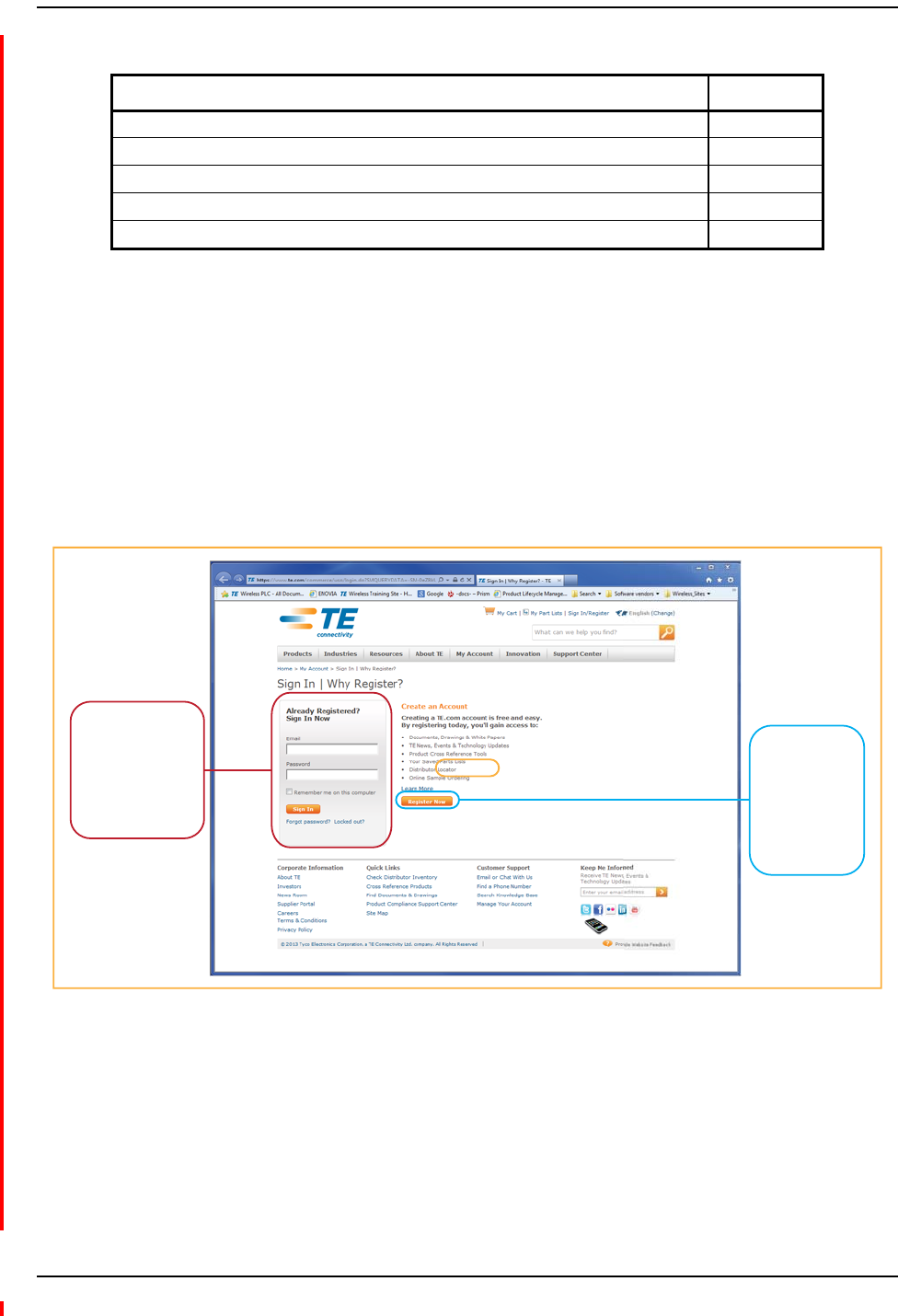
1ClickonthefollowingURLlink:
https://www.te.com/portal/wireless/
(Alternatively,entertheprecedingURLintoyourwebbrowser,andthenpressENTERonyour
keyboard.)
2AccesstotheCustomerPortalrequiresauseraccountandpassword.OntheSignInpage,do
oneofthefollowing:
3OntheWirelessCustomerPortalhomepageintheKnowledgeCenterpanel,clicktheManualsand
DataSheetslink.
4OntheManualsandDataSheetspage,dothefollowing:
aIntheDocumentRepositorypanel,scrolltothesectionfortheproductlineofthedocument
thatyouwanttoaccess.
bClickonthetitleofthemanualthatyouwishtoopen.
c(Optional)SavethePDFtoyourPCorlaptop.
Table7.InterReachSpectrumUserDocumentation
Title TECP Number
InterReach Spectrum Software Release 8.1 System Setup and Provisioning Guide TECP-77-215
InterReach Spectrum Host Unit Installation Guide TECP-77-220
InterReach Spectrum Expansion Module Group Installation Guide TECP-77-221
InterReach Spectrum Remote Access Unit Installation Guide TECP-77-222
FlexWave Prism OADM Splice Box Installation Guide TECP-77-208
If you have an
account, enter
your Email and
Password and
click Sign In.
If you don’t
have an
account, click
Register Now
and follow the
prompts.

Appendix D: Contacts and User Documentation
Page 30 InterReach Spectrum Remote Access Unit Installation Guide
© 2013 TE Connectivity Ltd TECP-77-222 Issue 2 • 300001759666 Rev B • December 2013

www.te.com/wireless