ADC Telecommunications S2782-011 SPT-S3-2323-12-HP User Manual
ADC Telecommunications Inc. SPT-S3-2323-12-HP
User Manual
FlexWave Spectrum
Remote Access Unit
Installation Guide
TECP-77-222 · Issue 3 · March 2015
TE Connectivity, TE and TE connectivity (logo) FlexWave, InterReach, InterReach Fusion and InterReach Unison are trademarks.
All other logos, products and/or company names referred to herein might be trademarks of their respective owners.
The information given herein, including drawings, illustrations and schematics which are intended for illustration purposes only, is believed to be reliable. However, TE
Connectivity makes no warranties as to its accuracy or completeness and disclaims any liability in connection with its use. TE Connectivity's obligations shall only be as
set forth in TE Connectivity's Standard Terms and Conditions of Sale for this product and in no case will TE Connectivity be liable for any incidental, indirect or
consequential damages arising out of the sale, resale, use or misuse of the product. Users of TE Connectivity products should make their own evaluation to determine
the suitability of each such product for the specific application.
This guide provides installation instructions for TE Connectivity FlexWave Spectrum Remote Access Units
(RAUs).
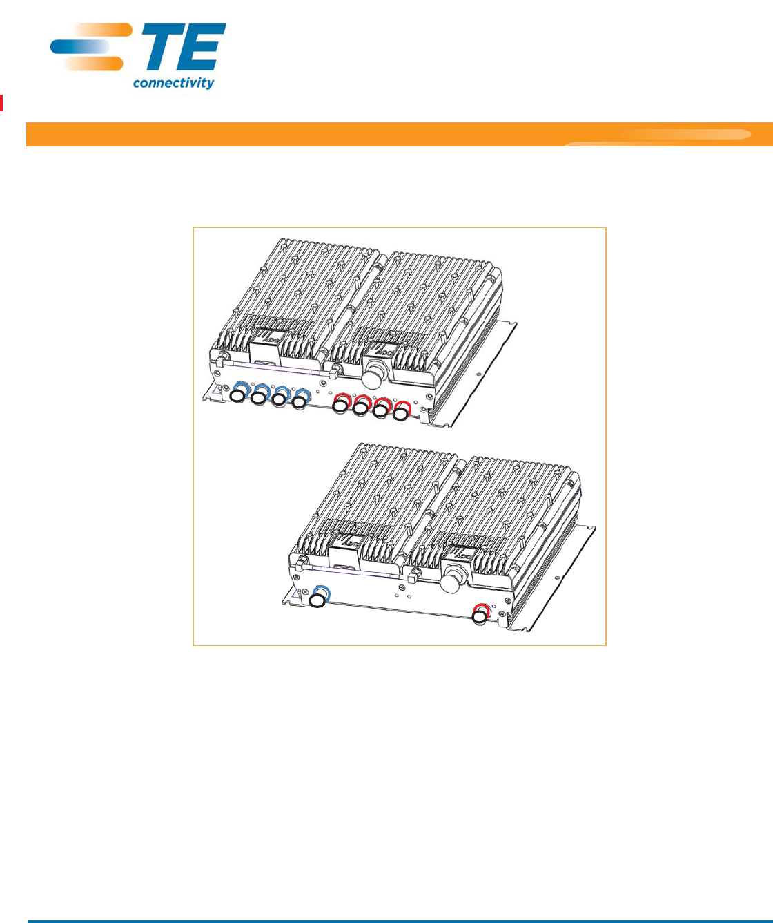
Main Remote Access Unit
Secondary Remote Access Unit

Page 2 FlexWave Spectrum Remote Access Unit Installation Guide
©2015 TE Connectivity TECP-77-222 Issue 3 • 300001759666 Rev C • March 2015
TABLE OF CONTENTS
Document Overview .......................................................................................................................................................................................... 3
Revision History...................................................................................................................................................................................................... 3
Document Cautions and Notes .............................................................................................................................................................................. 4
Abbreviations Used in this Guide ........................................................................................................................................................................... 4
Product Overview .............................................................................................................................................................................................. 5
Main Remote Access Units..................................................................................................................................................................................... 7
MRAU Ports, Cable, and Connectors.............................................................................................................................................................. 7
MRAU LEDs..................................................................................................................................................................................................... 8
Secondary Remote Access Units ............................................................................................................................................................................ 9
SRAU Ports, Cable, and Connectors ............................................................................................................................................................... 9
SRAU LEDs .................................................................................................................................................................................................... 10
RAU N Connectors................................................................................................................................................................................................ 11
Install the RAUs and Antennas ..........................................................................................................................................................................12
Mount the RAUs and Antennas............................................................................................................................................................................ 12
Connect the IFEU to the MRAU............................................................................................................................................................................ 13
Connect the MRAU to SRAUs ............................................................................................................................................................................... 14
Configure the MRAUs and SRAUs ........................................................................................................................................................................ 16
Specifications ....................................................................................................................................................................................................17
Remote Access Unit Specifications ...................................................................................................................................................................... 17
Spectrum System Specifications .......................................................................................................................................................................... 17
RF Specification ............................................................................................................................................................................................ 17
Propagation Delay ........................................................................................................................................................................................ 17
Nominal Passband Bandwidths and Specifications...................................................................................................................................... 17
System Gain Examples.................................................................................................................................................................................. 18
Composite Power Out of RAU .............................................................................................................................................................................. 19
75-Ohm CATV Cable Requirements and Specifications ......................................................................................................................................22
CATV Cable Requirements ................................................................................................................................................................................... 22
Belden 1695A Coax Specifications ....................................................................................................................................................................... 23
Description ................................................................................................................................................................................................... 23
Overall Physical Characteristics.................................................................................................................................................................... 23
Overall Nominal Electrical Characteristics.................................................................................................................................................... 24
Belden 7732A Coax Specifications ....................................................................................................................................................................... 25
Description ................................................................................................................................................................................................... 25
Overall Physical Characteristics.................................................................................................................................................................... 25
Overall Nominal Electrical Characteristics.................................................................................................................................................... 26
Omni Antenna Specifications ............................................................................................................................................................................27
Standards Certification......................................................................................................................................................................................28
Accessing User Documentation on the TE Customer Portal................................................................................................................................30
Contacting TE Connectivity................................................................................................................................................................................31

FlexWave Spectrum Remote Access Unit Installation Guide Page 3
TECP-77-222 Issue 3 • 300001759666 Rev C • March 2015 ©2015 TE Connectivity
DOCUMENT OVERVIEW
Table 1 lists the Standard RAUs that are supported in this document.
Table 1. Supported Spectrum Standard Remote Access Units
Catalog Number Description
Standard RAUs
Spectrum, 700 MIMO Secondary RAU, UpperC-LowerABC
Spectrum, 700 SISO-2100AWS Path 1 SEC RAU, UpperC-LowerABC
Spectrum, 700 Path 2 SISO-2100AWS Path 2 SEC RAU, UpperC-LowerABC
Spectrum, 800 Path 2-1900 Path 2 Secondary RAU
Spectrum, 800-900 SMR Secondary RAU
Spectrum, 800-2100AWS Path 1 Secondary RAU
Spectrum, 850-1900 Main RAU
Spectrum, 850 Path 2-1900 Path 2 Secondary RAU
Spectrum, 2100AWS MIMO Secondary RAU
Spectrum, 2100AWS Path 1-1900 Path 1 Main RAU
Spectrum, 2100AWS Path 1-1900 Path 2 Secondary RAU
High Power RAUs
Spectrum, 700 Path 1 uC/LABC-AWS HP Path 1 Secondary RAU
Spectrum, 700 Path 2 uC/LABC-AWS HP Path 2 Secondary RAU
Spectrum, 800 Path 2-1900 HP Path 2 Secondary RAU
Spectrum, 800 Path 3 - 1900 HP Path 1 Main RAU
Spectrum, 850 Path 1-1900 HP Path 1 Main RAU
Spectrum, 850 Path 2 - 1900 HP Path 2 Secondary RAU
FlexWave Spectrum, 2300 HPp1 - 2300 HPp2 Secondary RAU
Spectrum, 2600HP Path 1 - 2600HP Path 2 Secondary RAU
* This RAU is Class B Signal Booster; see “Part 90 Signal Boosters” on page 28.
Revision History
Issue Document Date Technical Updates
1 February 2013 Initial release.
2 August 2014 Added support for the 2600HP Path 1 - 2600HP Path 2 Secondary RAU, the 800 Path 3 - 1900 HP Path 1 Main RAU, and
the Path 2-1900 HP Path 2 Secondary RAU; added torque data in “Connect the IFEU to the MRAU” on page 13 and
“Connect the MRAU to SRAUs” on page 14.
3 March 2015 Adds support for 2300 HPp1 - 2300 HPp2 Secondary RAU.
SPT-S1-7070-1-MIMO
SPT-S2-70AWS-1-SISO
SPT-S2-70AWS-22-SISO
SPT-S1-8019-22*
SPT-S1-8090-1*
SPT-S1-80AWS-1*
SPT-M1-8519-1
SPT-S1-8519-22
SPT-S1-2121-1-MIMO
SPT-M1-AWS19-11
SPT-S1-AWS19-12
SPT-S3-70AWS-11-HP
SPT-S3-70AWS-22-HP
SPT-S3-8019-22-HP*
SPT-M3-8019-31-HP*
SPT-M3-8519-11-HP
SPT-S3-8519-22-HP
SPT-S3-2323-12-HP
SPT-S3-2626-12-HP

Page 4 FlexWave Spectrum Remote Access Unit Installation Guide
©2015 TE Connectivity TECP-77-222 Issue 3 • 300001759666 Rev C • March 2015
Document Cautions and Notes
Two types of messages, identified below, appear in the text:
CAUTION! Cautions indicate operations or steps that could cause personal injury, induce a safety problem in a managed
device, destroy or corrupt information, or interrupt or stop services.
NOTE: Notes contain information about special circumstances.
Abbreviations Used in this Guide
AWS Advanced Wireless Services
CATV Community Antenna Television
cm Centimeter
CUL Canadian Underwriters Laboratory
DART Digital-Analog Radio Transceiver
dB Decibel
DC Direct Current
DRU DART Remote Unit
F Fahrenheit
FCC Federal Communications Commission
FFEP Foam Fluorinated Ethylene Propylene
Ft Feet
FWD Forward
HP High Power
IC Industry Canada
IF Intermediate Frequency
IFEU IF Expansion Unit
LTE Long-Term Evolution
MHz Megahertz
MIMO Multiple-Input Multiple-Output
mm Millimeter
MRAU Main Remote Access Unit
RAU Remote Access Unit
REV Reverse
RF Radio Frequency
SISO Single-Input Single-Output
SMR Specialized Mobile Radio
SRAU Secondary Remote Access Unit
UL Underwriters' Laboratories, Inc.
Vdc Volts, direct current
WCS Wireless Communications Service

FlexWave Spectrum Remote Access Unit Installation Guide Page 5
TECP-77-222 Issue 3 • 300001759666 Rev C • March 2015 ©2015 TE Connectivity
PRODUCT OVERVIEW
Spectrum supports up to 8 bands in a single system. Each antenna location supports those bands in modular,
group pairings. Each location includes a Main Remote Access Unit (MRAU) that can power up to three additional
Secondary RAUs (SRAUs), each of which support two power amplifier pairs for a total of eight amplifiers. MRAUs
and SRAUs are grouped logically based on common service provider groupings and include: 850/1900, 700/700
MIMO, 800/900 SMR, 700 SISO/AWS, and so forth (see Table 1 on page 3). Adding frequency is as simple as
plugging in an SRAU to the existing MRAU (see Table 3 on page 19 through Table 5 on page 21 in “Specifications”).
RAUs are available in two different output power options: Standard and High Power. These can be “mixed and
matched” on a system to meet the specific needs of a venue.
Since Spectrum can be configured to support as many as four cascaded runs of sixteen total Expansion Module
Groups, the system configuration possibilities are seemingly endless and can scale to single systems that include
as many as 128 MRAU locations, with each of those locations supporting between one and eight RF bands. And
each of those band locations offers 26 dBm (P1dB) or 31 dBm (P1dB) of output power based on selecting
Standard or High Power (HP) RAUs.
The system may be scaled to add new bands or RAU location sites as-needed and offers great service flexibility
and performance relative to shared, wide-band amplifier systems. Each service provider may control their band
of interest and enjoy the predictability in consistent service at each RAU location independent of what other
operators are doing or the length the signal travels to the service area.
The RAUs are typically mounted above ceiling tiles or in out-of-sight locations as close as possible to the service
area.
Page 6 FlexWave Spectrum Remote Access Unit Installation Guide
©2015 TE Connectivity TECP-77-222 Issue 3 • 300001759666 Rev C • March 2015
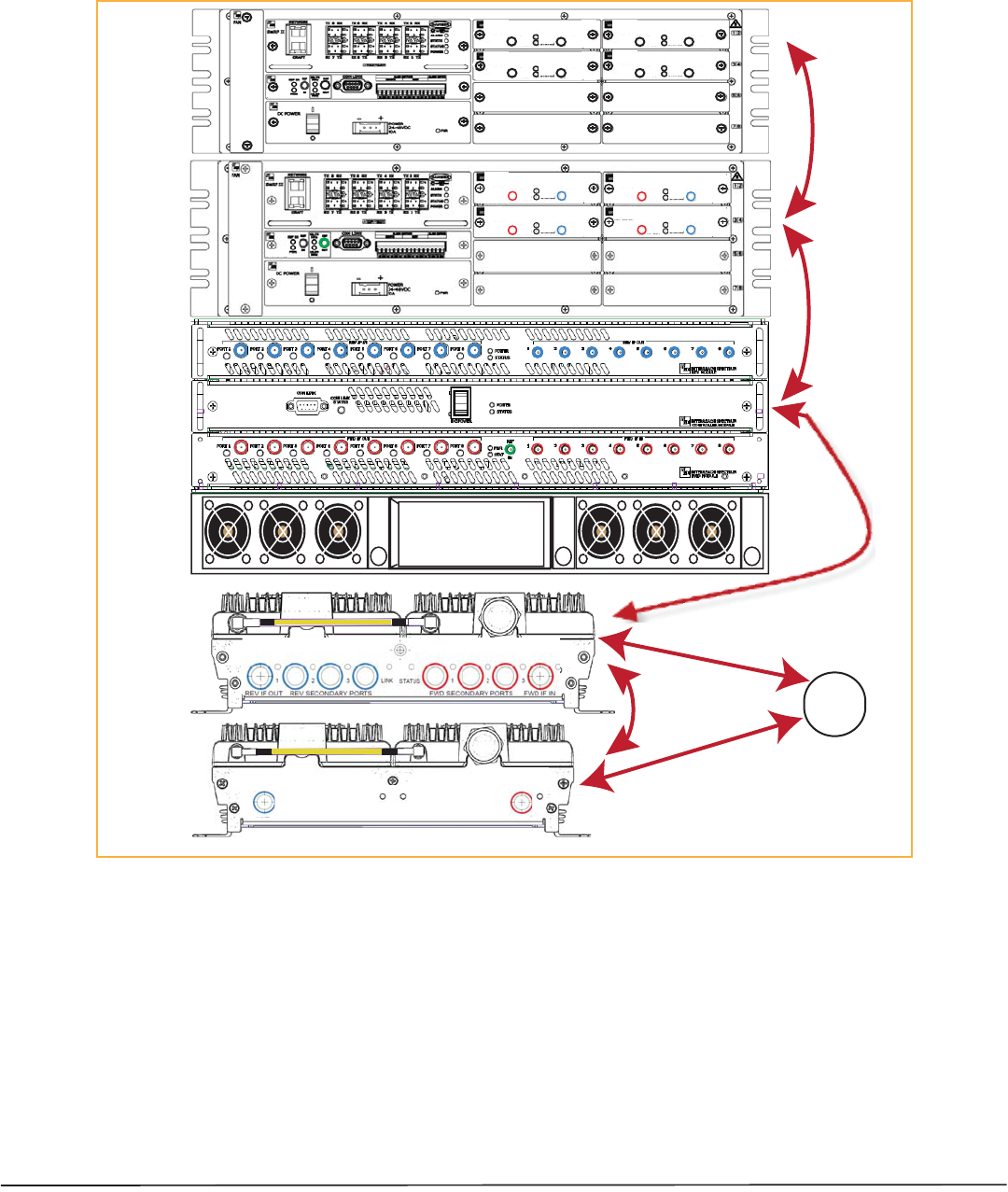
Figure 1 illustrates how RF and IF signals are sent between Spectrum units and modules.
LINK STATUS
SECONDARY
REV
SECONDARY
FWD
SECONDARY
REV
SECONDARY
FWD
LINK STATUS
REV IF OUT REV SECONDARY PORTS
1 2 3
FWD SECONDARY PORTS
1 2 3
FWD IF IN
LINK STATUS
Host
SRAU
MRAU
Power
Supply
IFEU
DRU
IF
RF
Omni
Antenna
R
F
R
F
x
x x
xx
x x
xx
x x
xx
x
x x
xx
x x
xx
x x
xx
x
REMOTE
SYSTEM II
IF DART
XXXXXXXXXX
BW XX MHz
FWD
IF OUT
REV
IF IN
PWR
STATUS
REMOTE
IF DART
XXXXXXXXXX
BW XX MHz
FWD
IF OUT
REV
IF IN
PWR
STATUS
REMOTE
IF DART
XXXXXXXXXX
BW XX MHz
FWD
IF OUT
REV
IF IN
PWR
STATUS
REMOTE
IF DART
XXXXXXXXXX
BW XX MHz
FWD
IF OUT
REV
IF IN
PWR
STATUS
REMOTE
IF
IF
HOST
SYSTEM II
RF DART
SMR900
FWD 935-940
REV 896-901
REV
RF OUT
FWD
RF IN
FWD NOT TO
EXCEED +5 dBm
PWR
STATUS
HOST
RF DART
SMR900
FWD 935-940
REV 896-901
REV
RF OUT
FWD
RF IN
FWD NOT TO
EXCEED +5 dBm
PWR
STATUS
HOST
RF DART
SMR900
FWD 935-940
REV 896-901
REV
RF OUT
FWD
RF IN
FWD NOT TO
EXCEED +5 dBm
PWR
STATUS
HOST
RF DART
SMR900
FWD 935-940
REV 896-901
REV
RF OUT
FWD
RF IN
FWD NOT TO
EXCEED +5 dBm
PWR
STATUS
HOST
NOTE: Units shown are not to scale.
NOTE: All FWD ports on all Modules are color-coded red and all REV ports are color-coded blue, which makes the DART
Remote Unit (DRU), IFEU, and RAU cabling process easier to complete.
Figure 1. REV and FWD Signals for the RAU
NOTE: This book refers to the Omni Antenna (4214-0727), which is the antenna that TE Connectivity recommends. Other
antennas may be used. For further information on the Omni Antenna, see “Omni Antenna Specifications” on
page 27.
FlexWave Spectrum Remote Access Unit Installation Guide Page 7
TECP-77-222 Issue 3 • 300001759666 Rev C • March 2015 ©2015 TE Connectivity
Main Remote Access Units
The Main Remote Access Unit (MRAU) receives FWD IF signals from an IF Expansion Unit (IFEU), which is part
of the Spectrum Expansion Module Group, using 75 CATV cable. The MRAU converts the IF signals to RF and
sends them to a passive RF antenna using 50 coaxial cable. The MRAU also receives configuration information
and power from and sends its status information to the IFEU.
The MRAU receives REV RF signals from a passive RF antenna using 50 coaxial cable. It converts the signals to
IF and sends them to the IFEU using 75 CATV cable.
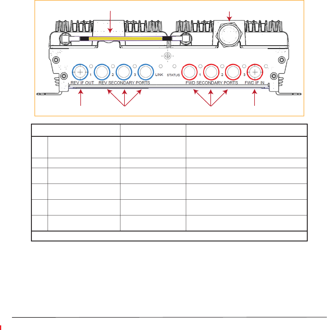
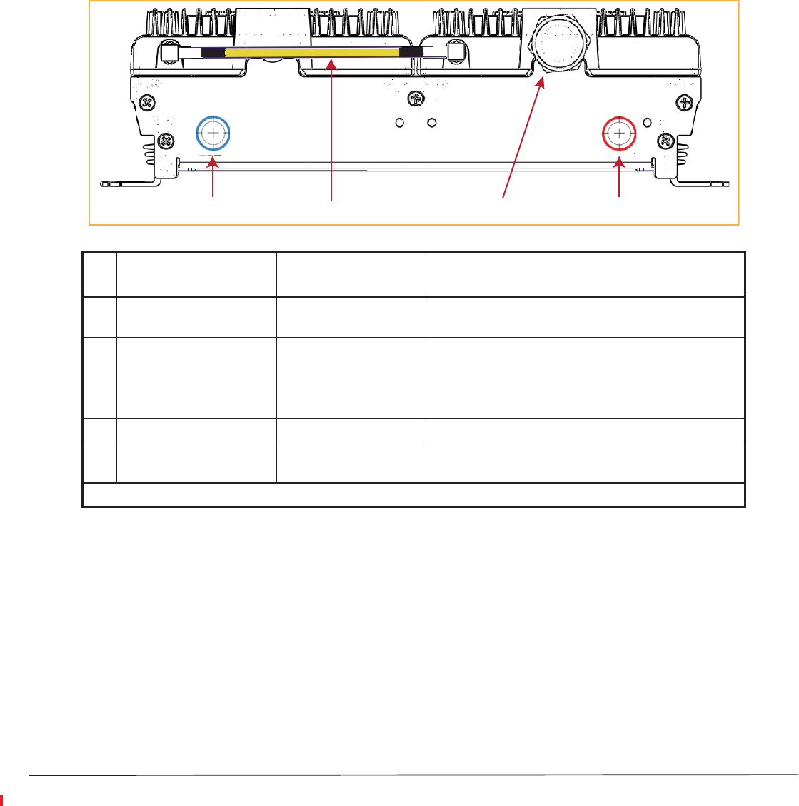
MRAU Ports, Cable, and Connectors
REV IF OUT REV SECONDARY PORTS
1 2 3
FWD SECONDARY PORTS
1 2 3
FWD IF IN
LINK STATUS
1 2
36 54
Ref # Component Device Function
1 RF jumper cable to connect
Band 1 to the diplexer on Band
2 RF module(1)
50 RF SMA-to-SMA cable
(or 50 RF N-to-SMA cable)
Connects two RF bands together so there is only one
N-type connector on the RAU to connect to an antenna.
2 Antenna port(s) 50 N-type connector Connects to an antenna. See Table 2 on page 11.
3 FWD IF IN connector F connector port Connects to the IFEU FWD Module IF OUT connector
via CATV cable.
4 FWD SECONDARY PORTS (1 - 3) F connector ports Connect to a SRAU SECONDARY FWD connector via
CATV cable.
5 REV SECONDARY PORTS (1 - 3) F connector ports Connect to a SRAU SECONDARY REV connector via
CATV cable.
6 REV IF OUT connector F connector port Connects to the IFEU REV Module IF IN connector via
CATV cable.
(1) The AWS/PCS MRAUs do NOT have an RF SMA cable—they have two Antenna ports.
Page 8 FlexWave Spectrum Remote Access Unit Installation Guide
©2015 TE Connectivity TECP-77-222 Issue 3 • 300001759666 Rev C • March 2015
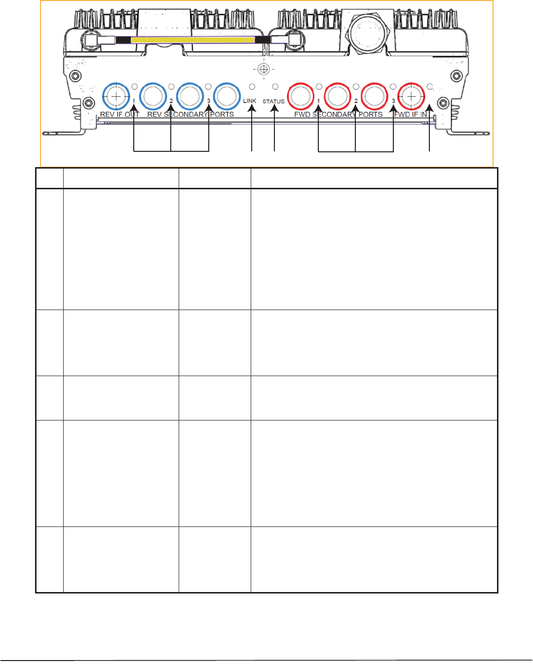
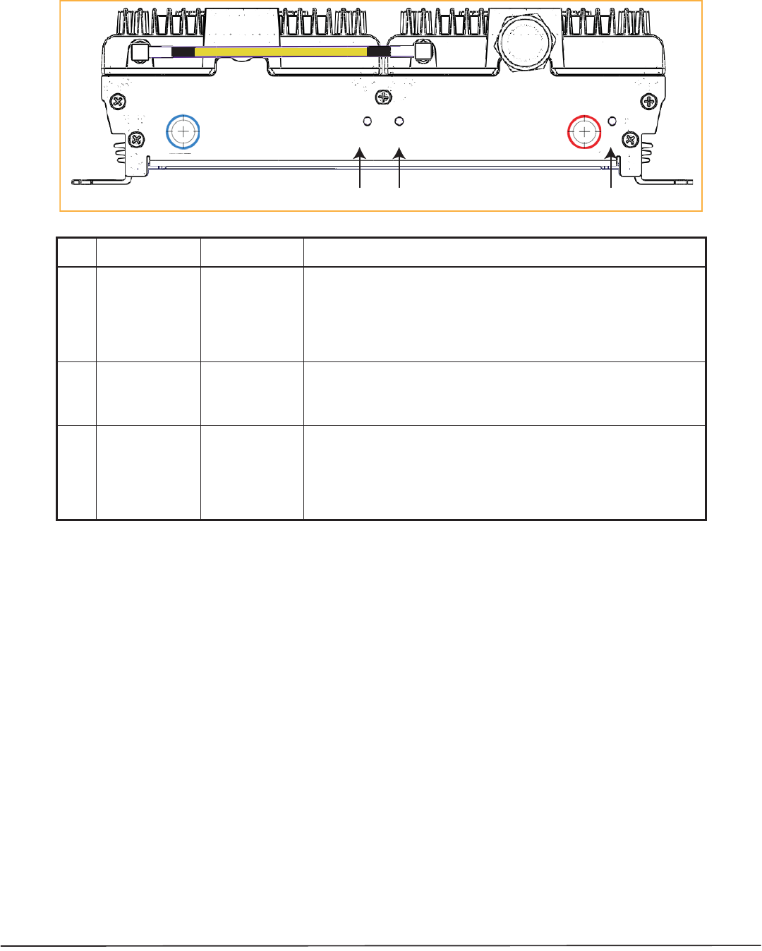
MRAU LEDs
REV IF OUT REV SECONDARY PORTS
1 2 3
FWD SECONDARY PORTS
1 2 3
FWD IF IN
LINK STATUS
415
2 3
Ref # LED LED Color Description
1FWD SECONDARY PORT
(1 - 3)
2 LINK
3 STATUS
4REV SECONDARY PORT
(1 - 3)
5 FWD IF IN
• Green • Downstream unit correctly connected; unit has no alarms or a
Minor alarm is active.
•Blinking Green • SRAU or band is set out-of-service.
• Yellow • FWD cable connected to SRAU, no REV cable connected.
• Blinking
yellow
• FWD and REV cables are not connected to the same port
number (incorrectly paired).
• Red • Major alarm in downstream unit, fault lockout, or SRAU
disconnected.
• Off • No SRAU previously connected.
• Green • MRAU receiving communications from the IFEU.
•Red • MRAU has not received communications from the IFEU for more
than 90 seconds.
• Off • During initial power up, MRAU is powering up and waiting for
IFEU communications.
• Green • Unit has no alarms or a Minor alarm is active.
•Blinking green • Unit or band is set out-of-service.
• Red • Major alarm detected.
• Green • Downstream unit correctly connected, unit has no alarms or
minor alarm
•Blinking Green • SRAU or band is set out-of-service.
• Blinking
Yellow
• FWD and REV cables are not connected to the same port
number (incorrectly paired).
• Red • Major alarm in downstream unit, fault lockout, or SRAU
disconnected.
• Off • No SRAU previously connected.
• Green • MRAU is powered on correctly.
•Yellow or
Blinking
Yellow
• There is an IFEU FWD connection, but there is no IFEU REV
connection or the IFEU REV connection is paired incorrectly.
• Off • Cable is not connected to the IFEU FWD port.
FlexWave Spectrum Remote Access Unit Installation Guide Page 9
TECP-77-222 Issue 3 • 300001759666 Rev C • March 2015 ©2015 TE Connectivity
Secondary Remote Access Units
A Secondary Remote Access Unit (SRAU) receives FWD IF signals from the MRAU, using 75 CATV cable. The
SRAU converts the IF signals to RF and sends them to a passive RF antenna using 50 coaxial cable. The SRAU,
through the MRAU, also receives configuration information and power from and sends its status information to
the IFEU.
The SRAU receives REV RF signals from a passive RF antenna using 50 coaxial cable. It converts the signals to
IF and sends them to the MRAU using 75 CATV cable.
SRAU Ports, Cable, and Connectors
142
3
LINK STATUS
SECONDARY
REV
SECONDARY
FWD
SECONDARY
REV
SECONDARY
FWD
LINK STATUS
Ref
#
Component Device Function
1 SECONDARY REV connector F connector port Connects to one of the MRAU REV SECONDARY ports (1 - 3)
via CATV cable.
2 RF SMA cable (1)
50 RF SMA-to-SMA cable
Connects two RF bands together when there is only one
N-type connector on the RAU.
For cases when there is an N-type connector for each RF
band (700MIMO or PCS/AWS), there will not be an SMA
cable.
3 Antenna port(s) 50 N-type connector Connects to an antenna. See Table 2 on page 11.
4 SECONDARY FWD connector F connector port Connects to one of the MRAU FWD SECONDARY ports (1 -
3) via CATV cable.
(1) The 700 MIMO SRAU does NOT have an RF SMA cable; it has two Antenna ports.
Page 10 FlexWave Spectrum Remote Access Unit Installation Guide
©2015 TE Connectivity TECP-77-222 Issue 3 • 300001759666 Rev C • March 2015
SRAU LEDs
LINK STATUS
SECONDARY
REV
SECONDARY
FWD
SECONDARY
REV
SECONDARY
FWD
LINK STATUS
312
Ref # LED LED Color Description
1 LINK
2 STATUS
3 SECONDARY FWD
• Green • SRAU receiving communications from the IFEU.
•Red • SRAU has not received communications from the IFEU for more than 90
seconds.
• Off • During initial power up, SRAU is powering up and waiting for IFEU
communications.
• Green • Unit has no alarms or a Minor alarm is active.
•Blinking Green • Unit or band is set out-of-service.
• Red • Major alarm detected.
• Green • SRAU is powered on correctly.
•Yellow or
Blinking
Yellow
• There is an MRAU FWD connection, but there is no MRAU REV connection
or the MRAU REV connection is paired incorrectly.
• Off • Cable is not connected to the MRAU FWD port.

FlexWave Spectrum Remote Access Unit Installation Guide Page 11
TECP-77-222 Issue 3 • 300001759666 Rev C • March 2015 ©2015 TE Connectivity
RAU N Connectors
Each RAU also has one or two 50- N-type connectors that connect to a passive antenna. Table 2 lists the number
of N-type connectors available on each RAU model.
Table 2. Number of N Connectors on RAUs
Catalog Number Description Number of RF
N
Connectors*
Standard RAUs
Spectrum, 700 MIMO Secondary RAU, UpperC-LowerABC 2
Spectrum, 700 SISO-2100AWS Path 1 SEC RAU, UpperC-LowerABC 1
Spectrum, 700 Path 2 SISO-2100AWS Path 2 SEC RAU, UpperC-LowerABC 1
Spectrum, 800 Path 2-1900 Path 2 Secondary RAU 1
Spectrum, 800-900 SMR Secondary RAU 1
Spectrum, 800-2100AWS Path 1 Secondary RAU 1
Spectrum, 850-1900 Main RAU 1
Spectrum, 850 Path 2-1900 Path 2 Secondary RAU 1
Spectrum, 2100AWS MIMO Secondary RAU 2
Spectrum, 2100AWS Path 1-1900 Path 1 Main RAU 2
Spectrum, 2100AWS Path 1-1900 Path 2 Secondary RAU 2
High Power RAUs
Spectrum, 700 Path 1 uC/LABC-AWS HP Path 1 Secondary RAU 1
Spectrum, 700 Path 2 uC/LABC-AWS HP Path 2 Secondary RAU 1
Spectrum, 800 Path 2-1900 HP Path 2 Secondary RAU 1
Spectrum, 800 Path 3 - 1900 HP Path 1 Main RAU 1
Spectrum, 850 Path 1-1900 HP Path 1 Main RAU 1
Spectrum, 850 Path 2 - 1900 HP Path 2 Secondary RAU 1
FlexWave Spectrum, 2300 HPp1 - 2300 HPp2 Secondary RAU 2
Spectrum, 2600HP Path 1 - 2600HP Path 2 Secondary RAU 2
* There are two bands per RAU, which results in two N connectors. When there is one N connector, the two bands are
combined internally and both bands use the single N connector.
SPT-S1-7070-1-MIMO
SPT-S2-70AWS-1-SISO
SPT-S2-70AWS-22-SISO
SPT-S1-8019-22*
SPT-S1-8090-1*
SPT-S1-80AWS-1*
SPT-M1-8519-1
SPT-S1-8519-22
SPT-S1-2121-1-MIMO
SPT-M1-AWS19-11
SPT-S1-AWS19-12
SPT-S3-70AWS-11-HP
SPT-S3-70AWS-22-HP
SPT-S3-8019-22-HP*
SPT-M3-8019-31-HP*
SPT-M3-8519-11-HP
SPT-S3-8519-22-HP
SPT-S3-2323-12-HP
SPT-S3-2626-12-HP

Page 12 FlexWave Spectrum Remote Access Unit Installation Guide
©2015 TE Connectivity TECP-77-222 Issue 3 • 300001759666 Rev C • March 2015
INSTALL THE RAUS AND ANTENNAS
Follow the steps in the order provided to install the RAUs and antennas.
Mount the RAUs and Antennas
CAUTION! Wet conditions increase the potential for receiving an electrical shock when installing or using electrically
powered equipment. To prevent electrical shock, never install or use electrical equipment in a wet location or
during a lightning storm.
CAUTION! This system is a RF Transmitter and continuously emits RF energy. Maintain a minimum 8-inch (20 cm) clearance
from the antenna while the system is operating. Whenever possible, shut down the RAN before servicing the
antenna.
NOTE: RAUs are suitable for use in environmental air space in accordance with Section 300-22(c) of the National Electrical
Code, and Sections 2-128, 12-010(3) and 12-100 of the Canadian Electrical Code, Part 1, CSA C22.1.
CAUTION! Install RAUs in indoor locations only. Do not connect an antenna installed in an outdoor location to a RAU, unless
it is in an approved AOC weatherproof NEMA4 housing.
CAUTION! Attach all RAUs securely to a stationary object (that is, a wall, pole, or ceiling brackets). To mount a RAU securely
to a wall, ceiling bracket, or pole, use #6 diameter fasteners in the four slotted mounting holes.
CAUTION! Do the following to maintain proper ventilation:
•Keep at least 76 mm (3-inch) clearance around the RAU.
•Do not stack RAUs on top of each other.
•Always mount the RAU with the solid face (containing the mounting holes) against the mounting surface.
NOTE: You can place the RAU, without its fastening hardware, on a flat surface, such as a shelf, desk, cabinet, or any other
horizontal surface that allows stable placement, with the mounting base facing down to the mounting surface.
CAUTION! If installing the RAU on a flat surface, the surface must be able to hold a minimum 7-pound load securely.
Do the following, in the order presented, to mount the RAUs and antennas:
1Mount all MRAU and SRAUs in the locations marked on the floor plans.
2Install the passive antennas according to the manufacturer’s installation instructions.
NOTE: It is common practice to install passive antennas below the ceiling. If you install a passive antenna above the
ceiling, when estimating the antenna coverage area, account for additional loss due to the ceiling material.
FlexWave Spectrum Remote Access Unit Installation Guide Page 13
TECP-77-222 Issue 3 • 300001759666 Rev C • March 2015 ©2015 TE Connectivity
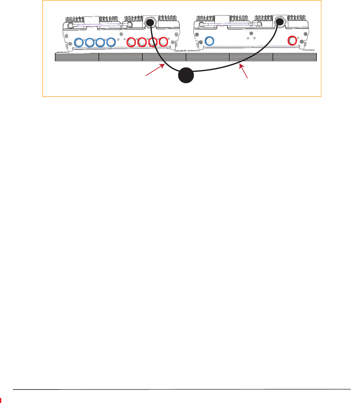
3Connect a passive multi-band antenna to the N connector on each RAU using coaxial cable with the least
amount of loss possible. (See “Omni Antenna Specifications” on page 27 for information on the Omni Antenna
ports.)
Omni Antenna
False Ceiling
SRAU N1
REV IF OUT REV SECONDARY PORTS
1 2 3
FWD SECONDARY PORTS
1 2 3
FWD IF IN
LINK STATUS
LINK STATUS
SECONDARY
REV
SECONDARY
FWD
MRAU N1
Coaxial cable
Coaxial cable
CAUTION! Firmly hand-tighten the N connector. DO NOT over-tighten the connector.
Connect the IFEU to the MRAU
NOTE: The IFEU should be powered up before starting this procedure; see the InterReach Spectrum Expansion Module
Group Installation Guide (TECP-77-167).
4Follow these rules for the CATV cables when connecting the IFEU to the MRAU:
•The FWD and REV cables should be close to the same length.
•The FWD and REV cables should be the same cable type (both RG6 or both RG11).
•A pair of CATV cables connects each MRAU to the IFEU. The IFEU REV Module IF IN port and the IFEU
FWD Module IF OUT port must match. For example, if IFEU REV Module IF IN Port 3 is used, use IFEU
FWD Module IF OUT Port 3.
•Refer to “75-Ohm CATV Cable Requirements and Specifications” on page 22 for information on maximum
RG-6 or RG-11 CATV cable lengths.
5Test the cable termination for each CATV cable before installing it.
Page 14 FlexWave Spectrum Remote Access Unit Installation Guide
©2015 TE Connectivity TECP-77-222 Issue 3 • 300001759666 Rev C • March 2015
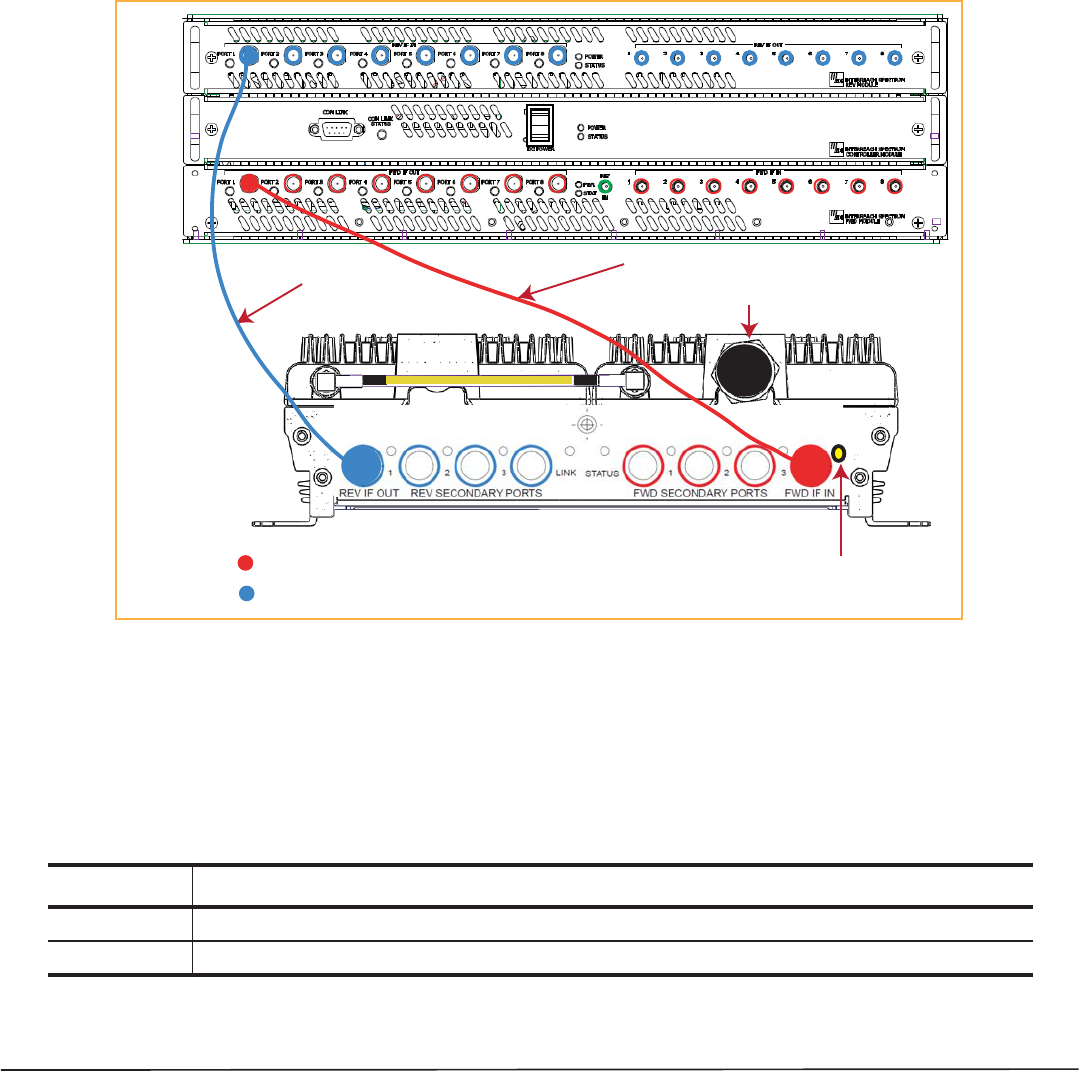
6Connect F connector CATV cables on the IFEU and MRAU, in the order given below.
If the LEDs do not perform as described in this procedure, refer to “MRAU LEDs” on page 8.
aConnect a CATV cable from one of the IFEU FWD Module IF OUT connectors (1 - 8) to the MRAU FWD IF
IN connector.
bConfirm that the MRAU FWD IF IN LED is yellow, which indicates a correct physical connection.
cConnect a CATV cable from the IFEU REV Module IF IN connector (1 - 8) to the MRAU REV IF OUT
connector, making sure that you pair the port used to the same port number selected in Step 6a.
If the connection is correct, the MRAU powers up and the MRAU FWD IF IN LED turns green.
Step 6a
IFEU
REV IF OUT REV SECONDARY PORTS
1 2 3
FWD SECONDARY PORTS
1 2 3
FWD IF IN
LINK STATUS
MRAU
To an antenna
Step 6c
KEY: IFEU FWD Module IF OUT connector to MRAU FWD IF IN connector
IFEU REV Module IF IN connector to MRAU REV IF OUT connector
Step 6b
NOTE: Torque applied to the F connector CATV cables should be 7 ±5% in-lbs.
Connect the MRAU to SRAUs
CAUTION! To prevent interference, do not install an 850/1900 MRAU passive antenna element near an 800/900 SRAU passive
antenna element. The 850 MHz band must be ~20 feet away from the 800/1900 SRAU’s passive antenna.
7Use one of the following 6’ and 20’ CATV RG6 jumpers, available for purchase from TE Connectivity, to
connect an MRAU to SRAUs.
TE Part Number Description Note
300469-0 6’ RG-6 Cable; F Male to F Male CATV cable that connects the MRAU to SRAUs. Two cables required per SRAU.
300469-1 20’ RG-6 Cable; F Male to F Male CATV cable that connects the MRAU to SRAUs. Two cables required per SRAU.
FlexWave Spectrum Remote Access Unit Installation Guide Page 15
TECP-77-222 Issue 3 • 300001759666 Rev C • March 2015 ©2015 TE Connectivity
8Test the cable termination for each CATV cable before installing it.
9Connect F connector CATV cables from the MRAU to an SRAU, in the order given below. If the LEDs do not
perform as described in this procedure, refer to “SRAU LEDs” on page 10.
aConnect a CATV cable from an MRAU FWD SECONDARY PORT (1, 2, or 3) F connector to the SRAU
SECONDARY FWD F connector.
bConfirm that the SRAU SECONDARY FWD LED is yellow, which indicates a correct physical connection.
cConnect a CATV cable from an MRAU REV SECONDARY PORT (1, 2, or 3) F connector to the SRAU
SECONDARY REV F connector, matching the same port number selected in Step 9a. That is, if in Step 9a
you connected an F connector to the MRAU FWD SECONDARY PORT 1, the paired CATV cable must
connect to the MRAU REV SECONDARY PORT 1.
If the connection is correct, the SRAU powers up and the SRAU SECONDARY FWD LED turns green.
MRAU
REV IF OUT REV SECONDARY PORTS
1 2 3
FWD SECONDARY PORTS
1 2 3
FWD IF IN
LINK STATUS
KEY: MRAU FWD Secondary port to SRAU Secondary FWD port
MRAU REV Secondary port to SRAU Secondary REV port
LINK STATUS
SECONDARY
REV
SECONDARY
FWD
SECONDARY
REV
SECONDARY
FWD
LINK STATUS
SRAU
To an antenna
To an antenna
To an IFEU
REV Module
IF IN connector
(1 - 8)
To an IFEU
FWD Module
IF OUT connector
(1 - 8)
Step 9a
Step 9b
Step 9c
NOTE: Torque applied to the F connector CATV cables should be 7 ±5% in-lbs.
Page 16 FlexWave Spectrum Remote Access Unit Installation Guide
©2015 TE Connectivity TECP-77-222 Issue 3 • 300001759666 Rev C • March 2015
10 Repeat Step 9 to install up to two more SRAUs, as per system design.
REV IF OUT REV SECONDARY PORTS
1 2 3
FWD SECONDARY PORTS
1 2 3
FWD IF IN
LINK STATUS
LINK STATUS
SECONDARY
REV
SECONDARY
FWD
LINK STATUS
SECONDARY
REV
SECONDARY
FWD
LINK STATUS
SECONDARY
REV
SECONDARY
FWD
MRAU
SRAU1
SRAU2
SRAU3
To an IFEU FWD Module
IF OUT connector (1 - 8)
To an IFEU REV Module
IF IN connector (1 - 8)
To an antenna
To an antenna
To an antenna
To an antenna
KEY: FWD
REV
Configure the MRAUs and SRAUs
Refer to the InterReach Spectrum™ Element Management System 7.3 User Manual (TECP-77-200) for information
on how to configure the MRAUs and SRAUs.

FlexWave Spectrum Remote Access Unit Installation Guide Page 17
TECP-77-222 Issue 3 • 300001759666 Rev C • March 2015 ©2015 TE Connectivity
SPECIFICATIONS
Remote Access Unit Specifications
Operating Temp -25°C to +50°C
Storage Temperature -40°C to +70°C
Humidity 10% to 95% non-condensing
Dimensions 11.50" W x 3.50" H x 9.00" D
Weight 7.49 Pounds
Power Source +54Vdc (from IFEU)
Spectrum System Specifications
RF Specification
Supported Frequency Blocks 2 per Remote Antenna Unit; 1-8 per Host Unit
Bandwidth 1.5 to 75 MHz non-contiguous
Propagation Delay
System Delay <12 microseconds per DART Remote Unit (DRU) link
(For example, in a cascade of 3 DRUs, the overall System Delay could be
up to 36 microseconds. This does not include Fiber Delay, just System
Delay along each segment of the cascade.)
Delay Management Digital (Manual or Automatic)
Nominal Passband Bandwidths and Specifications
Bandwidth
RF Frequency
TX RX
700 Lower ABC 728-746 698-716
700 Upper C 746-756 776-786
800 SMR 851-869 806-824
850 Cell 869-894 824-849
900 SMR 935-940 896-901
1900 PCS 1930-1995 1850-1915
2300 WCS 2350 - 2360 2305 - 2315
2100 AWS 2110-2155 1710-1755
2600 LTE 2620-2690 2500-2570

Low/Medium Power Level
700-900 MHz
Typical
Low/Medium Power Level
1900-2600 MHz
Typical
High
Power Level
1900-2600 MHz
Typical 3
TX RX TX RX TX RX
Average system gain with 180 m CATV 4 at 25°C (77° F) (dB) 9 to 401/432-1 to 30 9 to 401/432-1 to 30 9 to 48 -1 to 30
Ripple with 180 m CATV (dB) 2.5 3.0 3.5 4.0 3.5 4.0
Output IP3 (dBm) 38 38 43
Input IP3 (dBm) -8 -8 -8
Output 1 dB Compression Point (dBm) 26 26 31
Noise Figure 1 HU-1 EMG-8 RAUs (dB) 17 17 17
Noise Figure 1 HU-4 EMG-32 RAUs (dB) 23 23 23
1 Low Power is defined here as a Standard MRAU used with Standard SRAUs; see Table 3 on page 19.
2 Medium Power is defined here as a High Power MRAU used with Standard SRAUs; see Table 4 on page 20.
3 High Power is used to define a High Power MRAU used with High Power SRAUs; see Table 5 on page 21.
4 See “System Gain Examples” on page 18.
Page 18 FlexWave Spectrum Remote Access Unit Installation Guide
©2015 TE Connectivity TECP-77-222 Issue 3 • 300001759666 Rev C • March 2015
System Gain Examples
System Gain is the addition of the RF DART gain + the RAU gain. This section provides examples of system gain,
based on the following specifications:
1All Standard and High Power (HP) MRAUs and SRAUs have 0 db of RX gain
2Standard MRAU and SRAUs have 0 dB of TX gain
3The HP MRAU adds 3 dB of TX gain on its bands and all bands of Standard and HP SRAUs connected to it
4HP MRAUs and HP SRAUs add an additional 5 dB of TX gain on the 1900, 2100, and 2600 RF bands
Example A: All RAUs RX Configuration
RX Gain 850 MHz band: -1 to 30 dB (RF DART gain) + 0 dB (Standard MRAU and SRAU gain) = -1 to 30 dB
Example B: Low Power Level Configuration: SPT-M1-8519-1 + SPT-S2-70AWS-1-SISO
TX Gain 850 MHz band: 9 to 40 dB (RF DART gain) + 0 dB (Standard MRAU gain) = 9 to 40 dB
TX Gain 1900 MHz band: 9 to 40 dB (RF DART gain) +0 dB (Standard MRAU gain) = 9 to 40 dB
TX Gain 700 MHz band: 9 to 40 dB (RF DART gain) + 0 dB (Standard SRAU with Standard MRAU gain) = 9 to 40 dB
TX Gain 2100 MHz band: 9 to 40 dB (RF DART gain) + 0 dB (Standard SRAU with Standard MRAU gain) = 9 to 40
dB

FlexWave Spectrum Remote Access Unit Installation Guide Page 19
TECP-77-222 Issue 3 • 300001759666 Rev C • March 2015 ©2015 TE Connectivity
Example C: Medium Power Level Configuration: SPT-M3-8519-11-HP + SPT-S2-70AWS-1-SISO
TX Gain 850 MHz band: 9 to 40 dB (RF DART gain) + 3 dB (HP MRAU gain) = 12 to 43 dB
TX Gain 1900 MHz band: 9 to 40 dB (RF DART gain) + 3 dB + 5 dB (HP MRAU gain + added HP 1900 band gain) =
17 to 48 dB
TX Gain 700 MHz band: 9 to 40 dB (RF DART gain) + 3 dB (Standard SRAU with MRAU gain) = 12 to 43 dB
TX Gain 2100 MHz band: 9 to 40 dB (RF DART gain) + 3 dB (Standard SRAU with MRAU gain) = 12 to 43 dB
Example D: High Power Level Configuration: SPT-M3-8519-11-HP + SPT-S3-70AWS-11-HP
TX Gain 850 MHz band: 9 to 40 dB (RF DART gain) + 3 dB (HP MRAU gain) = 12 to 43 dB
TX Gain 1900 MHz band: 9 to 40 dB (RF DART gain) + 3 dB + 5 dB (HP MRAU gain + added HP 1900 band gain) =
17 to 48 dB
TX Gain 700 MHz band: 9 to 40 dB (RF DART gain) + 3 dB (HP SRAU with HP MRAU gain) = 12 to 43 dB
TX Gain 2100 MHz band: 9 to 40 dB (RF DART gain) + 3 dB + 5 dB (HP SRAU with HP MRAU gain + added HP 2100
band gain) = 17 to 48 dB
Composite Power Out of RAU
Table 3. Low Power Level: Standard MRAU with SRAUs
Power per Carrier (dBm) per Band
RF Frequency Number of RF Carriers
TX RX 1 P-out 2 P-out 4 P-Out 8 P-out
Standard MRAUs: 700 Upper C 746-756 776-786 15.0 12.0 9.0 6.0 LTE
•SPT-M1-8519-1 700 Lower ABC 728-746 698-716
•SPT-M1-AWS19-11
800 SMR 851-869 806-824
17.5 14.0 10.0 6.5 iDEN
26.0 19.5 13.5 8.5 APCO 25 C4FM
Standard SRAUs 15.0 12.0 9.0 6.0 CDMA
•SPT-S1-8090-1 15.0 12.0 9.0 6.0 LTE
•SPT-S1-7070-1-MIMO
850 Cell 869-894 824-849
26.0 20.0 14.0 9.0 GSM
•SPT-S1-80AWS-1 23.0 17.5 12.0 8.0 EDGE
•SPT-S2-70AWS-1-SISO 15.0 12.0 9.0 6.0 CDMA
•SPT-S2-70AWS-22-SISO 15.0 12.0 9.0 6.0 WCDMA
•SPT-S1-AWS19-12 15.0 12.0 9.0 6.0 LTE
•SPT-S1-2121-1-MIMO 900 SMR 935-940 896-901 17.5 14.0 10.0 6.5 iDEN
•SPT-S1-8019-22 26.0 20.0 13.5 9.0 APCO 25 C4FM
•SPT-S1-8519-22
1900 PCS 1930-1995 1850-1915
26.0 20.0 14.0 9.0 GSM
23.0 17.5 12.0 8.0 EDGE
15.0 12.0 9.0 6.0 CDMA
15.0 12.0 9.0 6.0 WCDMA
15.0 12.0 9.0 6.0 LTE
2100 AWS 2110-2155 1710-1755 15.0 12.0 9.0 6.0 WCDMA
15.0 12.0 9.0 6.0 LTE

Table 4. Medium Power Level: High Power MRAUs1 used with Standard SRAUs
Power per Carrier (dBm) per Band
RF Frequency Number of RF Carriers
TX RX 1 P-out 2 P-out 4 P-Out 8 P-out
700 Upper C 746-756 776-786 18.0 15.0 12.0 9.0 LTE
700 Lower ABC 728-746 698-716
800 SMR 851-869 806-824
17.5 14.0 10.0 6.5 iDEN
26.0 19.5 13.5 8.5 APCO 25 C4FM
Standard SRAUs 18.0 15.0 12.0 9.0 CDMA
•SPT-S1-8090-1 18.0 15.0 12.0 9.0 LTE
•SPT-S1-7070-1-MIMO
850 Cell 869-894 824-849
26.0 20.0 14.0 9.0 GSM
•SPT-S1-80AWS-1 23.0 17.5 12.0 8.0 EDGE
•SPT-S2-70AWS-1-SISO 18.0 15.0 12.0 9.0 CDMA
•SPT-S2-70AWS-22-SISO 18.0 15.0 12.0 9.0 WCDMA
•SPT-S1-AWS19-12 18.0 15.0 12.0 9.0 LTE
•SPT-S1-2121-1-MIMO 900 SMR 935-940 896-901 17.5 14.0 10.0 6.5 iDEN
•SPT-S1-8019-22 26.0 19.5 13.5 8.5 APCO 25 C4FM
•SPT-S1-8519-22
1900 PCS 1930-1995 1850-1915
26.0 20.0 14.0 9.0 GSM
23.0 17.5 12.0 8.0 EDGE
18.0 15.0 12.0 9.0 CDMA
18.0 15.0 12.0 9.0 WCDMA
18.0 15.0 12.0 9.0 LTE
2100 AWS 2110-2155 1710-1755 18.0 15.0 12.0 9.0 WCDMA
18.0 15.0 12.0 9.0 LTE
1 See power per carrier of HP MRAU from Table 5 on page 21.
Page 20 FlexWave Spectrum Remote Access Unit Installation Guide
©2015 TE Connectivity TECP-77-222 Issue 3 • 300001759666 Rev C • March 2015

Table 5. High Power Level: High Power MRAU with High Power SRAUs
Power per Carrier (dBm) per Band
RF Frequency Number of RF Carriers
TX RX 1 P-out 2 P-out 4 P-Out 8 P-out
700 Upper C 746-756 776-786 18.0 15.0 12.0 9.0 LTE
High Power MRAU 700 Lower ABC 728-746 698-716
•SPT-M3-8519-11-HP
800 SMR 851-869 806-824
17.5 14.0 10.0 6.5 iDEN
•SPT-M3-8019-31-HP 26.0 19.5 13.5 8.5 APCO 25 C4FM
18.0 15.0 12.0 9.0 CDMA
High Power SRAUs 18.0 15.0 12.0 9.0 LTE
•SPT-S3-70AWS-11-HP
850 Cell 869-894 824-849
26.0 20.0 14.0 9.0 GSM
•SPT-S3-70AWS-22-HP 23.0 17.5 12.0 8.0 EDGE
•SPT-S3-8019-22-HP
•SPT-S3-8519-22-HP
18.0 15.0 12.0 9.0 CDMA
•SPT-S3-2323-12-HP
•SPT-S3-2626-12-HP
18.0 15.0 12.0 9.0 WCDMA
18.0 15.0 12.0 9.0 LTE
900 SMR 935-940 896-901 17.5 14.0 10.0 6.5 iDEN
26.0 19.5 13.5 8.5 APCO 25 C4FM
1900 PCS 1930-1995 1850-1915
26.0 23.0 19.0 14.0 GSM
26.0 22.5 17.0 13.0 EDGE
23.0 20.0 17.0 14.0 CDMA
23.0 20.0 17.0 14.0 WCDMA
23.0 20.0 17.0 14.0 LTE
2100 AWS 2110-2155 1710-1755 23.0 20.0 17.0 14.0 WCDMA
23.0 20.0 17.0 14.0 LTE
2300 WCS 2350 - 2360 2305 - 2315 23.0 20.0 17.0 14.0 LTE
2600 LTE 2620-2690 2500-2570 23.0 20.0 17.0 14.0 WCDMA
23.0 20.0 17.0 14.0 LTE
FlexWave Spectrum Remote Access Unit Installation Guide Page 21
TECP-77-222 Issue 3 • 300001759666 Rev C • March 2015 ©2015 TE Connectivity
NOTE: Models SPT-M3-8019-31-HP and SPT-S3-8019-22-HP - Industry Canada Mean Output Power is 24.33 dBm (800
SMR) and 26.83 dBm (1900 PCS).
Page 22 FlexWave Spectrum Remote Access Unit Installation Guide
©2015 TE Connectivity TECP-77-222 Issue 3 • 300001759666 Rev C • March 2015
75-OHM CATV CABLE REQUIREMENTS AND SPECIFICATIONS
The 75-Ohm CATV Cable:
•connects the IFEU to MRAU(s) and the MRAU(s) to the SRAU(s)
•transmits (FWD) multiband and receives (REV) IF signals
•delivers DC electrical power to the RAUs. The Spectrum IFEU DC voltage output is +54Vdc nominal. If the
IFEU reaches its current limit, a current-limiting circuit protects it.
•carries configuration and status information
•uses 75 type-F connectors with captive center pins.
CATV Cable Requirements
Belden CATV cable or equivalent is required (see Figure 2).
•For the RG-6 cable, use a Belden 1695A Coax.
•For the RG-11 cable, use a Belden 7732A Coax.
RG-11
Belden 1695A Coax
RG-6
Belden 7732A Coax
NOTE: TE Connectivity requires solid copper center conductor CATV cable for proper DC voltage to the RAU and maximum
distances.
Figure 2. Belden 1695A and 7732A Coax Cables
•Use RG-6 or RG-11 CATV cable between the IFEU and MRAU, the typical lengths of which are listed below.
Cable Type
Minimum
Length
Maximum
Length
Meters Feet Meters Feet
RG-6 0 0 125 410
RG-11 0 0 180 590

FlexWave Spectrum Remote Access Unit Installation Guide Page 23
TECP-77-222 Issue 3 • 300001759666 Rev C • March 2015 ©2015 TE Connectivity
•Use only RG-6 CATV cable between the MRAU and SRAU, the lengths of which are listed below.
RG-6 Cable Meters Feet
Typical 2 6.56
800/900 iDEN to 850 CELL 6 19.68
800 AWS to 850 CELL 6 19.68
Belden 1695A Coax Specifications
Description
RG-6/U type, 18 AWG solid 0.040-inch bare copper conductor, plenum, foam Fluorinated Ethylene Propylene (FEP)
insulation, Duofoil® + tinned copper braid shield (95% coverage), Flamarrest® jacket.
Overall Physical Characteristics
Conductor One Coax
18 AWG
Solid stranding
Bare Copper (BC) conductor material
0.040-inch diameter
Insulation Teflon®
Foam Fluorinated Ethylene Propylene (FFEP)
0.170-inch diameter
Outer Shield Layer 1 Duofoil®
Tape
Aluminum Foil-Polyester Tape-Aluminum Foil
100% coverage
Outer Shield Layer 2 Braid
Tinned Copper (TC)
95% coverage
Outer Jacket Flamarrest®
Low Smoke Polyvinyl Chloride (LS PVC)
Overall Cabling 0.234-inch overall nominal diameter

Page 24 FlexWave Spectrum Remote Access Unit Installation Guide
©2015 TE Connectivity TECP-77-222 Issue 3 • 300001759666 Rev C • March 2015
Overall Nominal Electrical Characteristics
Characteristic Impedance 75.000
Inductance 0.103 H/ft.
Capacitance Conductor to Shield 16.100 (pF/ft.)
Velocity of Propagation 82 (%)
Delay 1.240 (ns/ft.)
Conductor DC Resistance 6.400 @ 20°C (/1000 ft.)
Outer Shield DC Resistance 2.800 @ 20°C (/1000 ft.)
Attenuation
Freq. (MHz) Attenuation (dB/100 ft.)
1.000 0.240
3.580 0.450
5.000 0.550
7.000 0.650
10.000 0.750
67.500 1.740
71.500 1.780
88.500 1.940
100.000 2.100
135.000 2.400
143.000 2.500
180.000 2.800
270.000 3.400
360.000 4.000
540.000 5.200
720.000 6.100
750.000 6.200
1000.000 7.300
1500.000 9.200
2000.000 10.900
2250.000 11.600
3000.000 13.700

FlexWave Spectrum Remote Access Unit Installation Guide Page 25
TECP-77-222 Issue 3 • 300001759666 Rev C • March 2015 ©2015 TE Connectivity
Belden 7732A Coax Specifications
Description
RG-11/U type, 14 AWG solid 0.064-inch bare copper conductor, plenum, foam FEP insulation, Duofoil® + tinned
copper braid shield (95% coverage), fluorocopolymer jacket.
Overall Physical Characteristics
Conductor One Coax
18 AWG
Solid stranding
Bare Copper (BC) conductor material
0.064-inch diameter
Insulation Teflon®
Foam Fluorinated Ethylene Propylene (FFEP)
0.274-inch diameter
Outer Shield Layer 1 Duofoil®
Tape
Aluminum Foil-Polyester Tape-Aluminum Foil
100% coverage
Outer Shield Layer 2 Braid
Tinned Copper (TC)
95% coverage
Outer Jacket Fluorocopolymer (PVDF)
Overall Cabling 0.348-inch overall nominal diameter

Page 26 FlexWave Spectrum Remote Access Unit Installation Guide
©2015 TE Connectivity TECP-77-222 Issue 3 • 300001759666 Rev C • March 2015
Overall Nominal Electrical Characteristics
Characteristic Impedance 75.000
Inductance 0.091 H/ft.
Capacitance Conductor to Shield 16.300 (pF/ft.)
Velocity of Propagation 83 (%)
Delay 1.220 (ns/ft.)
Conductor DC Resistance 2.500 @ 20°C (/1000 ft.)
Outer Shield DC Resistance 1.600 @ 20°C (/1000 ft.)
Attenuation
Freq. (MHz) Attenuation (dB/100 ft.)
1.000 0.150
3.580 0.260
5.000 0.300
7.000 0.340
10.000 0.400
67.500 1.200
71.500 1.240
88.500 1.400
100.000 1.500
135.000 1.780
143.000 1.840
180.000 2.090
270.000 2.600
360.000 3.100
540.000 3.890
720.000 4.570
750.000 4.680
1000.000 5.500
1500.000 6.910
2000.000 8.130
2250.000 9.200
3000.000 10.200

FlexWave Spectrum Remote Access Unit Installation Guide Page 27
TECP-77-222 Issue 3 • 300001759666 Rev C • March 2015 ©2015 TE Connectivity
OMNI ANTENNA SPECIFICATIONS
The Omni Antenna (4214-0727 or the Low PIM 4214-0727-P), shown in Figure 3, is a round radome with the
following specifications:
Ceiling mount, vertically polarized, omni directional antenna
Figure 3. Omni Antenna
Port 1 Port 2 Port 3
Gain, typical 2 dBi @ 698-960 MHz 2 dBi @ 698-960 MHz 3 dBi @1710-2170 MHz
3 dBi @ 1710-2170 MHz 3 dBi @ 1710-2170 MHz 3 dBi @ 2496-2690 MHz
Nominal impedance 50 Ohm
Polarization Vertical
VSWR < 2:1
Port-to-port isolation >15 dB min, 22 dB typical
PIM (@2x43 dBm) -153 dBc
Power rating 5 Watt
Mechanical
Dimension of Antenna (DxH) 215 x 72 mm
Weight Less than or equal to 1.65 lbs (0.75kg), including pigtails
Connector N (male)
Cable (pigtail) length 6 feet, plenum rated cable
Color White, UV protected plastic for outdoor use
Mounting hardware Screws, anchor, and butterfly nut for ceiling tile mount
Environmental
Operating temperature - 40°C to + 65°C
Shipping and Handling ISTA Procedure 1A
Ingress protection IP-42
Flammability UL94V0 (Materials)
Compliance ROHS compliant
NOTE: Two antennas per RAU is required for MIMO performance.
CAUTION! Maximum gain antenna allowed is 3dBi

Page 28 FlexWave Spectrum Remote Access Unit Installation Guide
©2015 TE Connectivity TECP-77-222 Issue 3 • 300001759666 Rev C • March 2015
STANDARDS CERTIFICATION
Federal Communications Commission (FCC)
This equipment complies with the applicable sections of Title 47 CFR, Part 22 (800 MHz Cellular), Part 24 (1900 MHz - PCS),
Part 90 (800/900 - SMR), and Part 27 (700 MHz, 2100 MHz - AWS).
Signal Boosters
WARNING. This is NOT a CONSUMER device. It is designated for installation by FCC LICENSEES and QUALIFIED
INSTALLERS. You MUST have an FCC LICENSE or express Consent of an FCC Licensee to operate this device. Unauthorized
use may result in Significant forfeiture penalties, including penalties in excess of $100,000 for each continuing violation.
Part 90 Signal Boosters
The following statement is applicable to the following RAUs that are documented in this installation guide:
SPT-M3-8019-31-HP, SPT-S1-8019-22, SPT-S1-8090-1, SPT-S1-80AWS-1, SPT-S3-8019-22-HP.
WARNING. This is NOT a CONSUMER device. It is designated for installation by FCC LICENSEES and QUALIFIED
INSTALLERS. You MUST have an FCC LICENSE or express Consent of an FCC Licensee to operate this device. You MUST
register Class B signal boosters (as defined in 47 CFR 90.219) online at http://www.fcc.gov/signal-boosters/registration.
Unauthorized use may result in Significant forfeiture penalties, including penalties in excess of $100,000 for each continuing
violation.
Industry Canada (IC)
This equipment complies with the applicable sections of RSS-131- Zone Enhancers for the Land Mobile Service. The term
“IC:” before the radio certification number only signifies that Industry Canada Technical Specifications were met.
The Manufacturer's rated output power of this equipment is for single carrier operation. For situations when multiple
carrier signals are present, the rating would have to be reduced by 3.5 dB, especially where the output signal is re-radiated
and can cause interference to adjacent band users. This power reduction is to be by means of input power or gain reduction
and not by an attenuator at the output of the device.
NOTE: The U. S. Federal Communications Commission (FCC) has developed guidelines for evaluation of human exposure
to RF emissions. The guidelines incorporate limits for Maximum Permissible Exposure (MPE) for power density of
transmitter operating at frequencies between 300 kHz and 100 GHz. Limits have been set for portable, mobile, and
fixed equipment. TE Connectivity products fall in the category of fixed equipment; products intended to be
permanently secured and exposures are evaluated for distances greater than 40cm (15.75”). Portable devices fall
into exposures of less than 20cm, where SAR evaluations are used.
Antenna gain is restricted to 1.5 W ERP (2.49 W EIRP) in order to satisfy RF exposure compliance requirements.
If higher than 1.5 W ERP, routine MPE evaluation is needed. The antennas should be installed to provide at
least 40cm from all persons to satisfy MPE requirements of FCC Part 2, 2.1091.
This device complies with Industry Canada licence-exempt RSS standard(s). Operation is subject to the following two
conditions: (1) this device may not cause interference, and (2) this device must accept any interference, including
interference that may cause undesired operation of the device.
Le présent appareil est conforme aux CNR d’Industrie Canada applicables aux appareils radio exempts de licence.
L’exploitation est autorisée aux deux conditions suivantes: (1) l’appareil ne doit pas produire de brouillage, et (2)
l’utilisateur de l’appareil doit accepter tout brouillage radioélectrique subi, même si le brouillage est susceptible d’en
compromettre le fonctionnement.
The device meets the exemption from the routine evaluation limits in section 2.5 of RSS 102 and compliance with RSS-102
RF exposure, users can obtain Canadian information on RF exposure and compliance.
Le dispositif rencontre l'exemption des limites courantes d'évaluation dans la section 2.5 de RSS 102 et la conformité à
l'exposition de RSS-102 rf, utilisateurs peut obtenir l'information canadienne sur l'exposition et la conformité de rf.

FlexWave Spectrum Remote Access Unit Installation Guide Page 29
TECP-77-222 Issue 3 • 300001759666 Rev C • March 2015 ©2015 TE Connectivity
UL/CUL
This equipment will be installed in a restricted access location. This equipment complies, per UL and CUL 50, Standard for
Enclosures for Electrical Equipment.
This equipment complies with UL and CUL 60950-1 Standard for Safety for Information Technology Equipment, including
Electrical Business Equipment.
All InterReach Spectrum RAUs are Plenum rated and suitable for use in environmental air space in accordance with Section
300-22(C) of the National Electrical Code, and Sections 2-128, 12-010(3) and 12-100 of the Canadian Electrical Code, Part
1, CSA C22.1.
This equipment is UL Plenum rated under UL 2043.
CAUTION! Modifications not expressly approved by the party responsible for compliance could void the user's authority to
operate the equipment.

Page 30 FlexWave Spectrum Remote Access Unit Installation Guide
©2015 TE Connectivity TECP-77-222 Issue 3 • 300001759666 Rev C • March 2015
ACCESSING USER DOCUMENTATION ON THE TE CUSTOMER PORTAL
You can access additional user documentation on the TE Customer Portal, as described below.
1Click on the following URL link:
https://www.te.com/portal/wireless/
(Alternatively, enter the preceding URL into your web browser, and then press ENTER on your keyboard.)
2Access to the Customer Portal requires a user account and password. On the Sign In page, do one of the
following:
•If you have an account, in the Already Registered? Sign In Now panel, enter your Email and Password, and
then click Sign In.
•If you don’t have an account, under Create an Account, click Register Now and follow the prompts.
3On the Wireless Customer Portal home page in the Knowledge Center panel, click the Manuals and Data Sheets
link.
4On the Manuals and Data Sheets page, do the following:
aIn the Document Repository panel, scroll to the section for the product line of the document that you want
to access.
bClick on the title of the manual that you wish to open.
c(Optional) Save the PDF to your computer.

FlexWave Spectrum Remote Access Unit Installation Guide Page 31
TECP-77-222 Issue 3 • 300001759666 Rev C • March 2015 ©2015 TE Connectivity
CONTACTING TE CONNECTIVITY
Telephone Numbers
Sales
Asia Pacific +65-6294-9948
France 0800 914032
Germany 0180 2232923
Italy 0800 782374
Spain 900 983291
United Kingdom 0800 960236
USA or Canada 1-800-366-3891
Extension 73000
Connectivity Extension 73475
Wireless Extension 73476
Technical Support
USA or Canada 1-800-530-9960
Elsewhere +1-952-917-0761
Online Access
Customer Portal
https://www.te.com/portal/wireless/
Technical Support for Wireless Products
http://www.te.com/WirelessSupport
www.te.com/wireless