ADC Telecommunications SP00AWSH URH Host Card User Manual 75348p1
ADC Telecommunications Inc URH Host Card 75348p1
Users Manual
ADC FlexWave™ Universal
Radio Head (URH) Host Unit
Installation Instructions
ADCP-75-348 • Issue 1 • 04/2008ADCP-75-348 • Issue 1 • 04/2008
1427955 Rev A
22408-A

ADCP-75-348 • Issue 1 • 04/2008 • Preface
Page ii
COPYRIGHT
© 2008, ADC Telecommunications, Inc.
All Rights Reserved
REVISION HISTORY
TRADEMARK INFORMATION
ADC is a registered trademark of ADC Telecommunications, Inc., FlexWave is a trademark of ADC Telecommunications, Inc.
DISCLAIMER OF LIABILITY
Contents herein are current as of the date of publication. ADC reserves the right to change the contents without prior notice. In no
event shall ADC be liable for any damages resulting from loss of data, loss of use, or loss of profits and ADC further
disclaims any and all liability for indirect, incidental, special, consequential or other similar damages. This disclaimer of
liability applies to all products, publications and services during and after the warranty period.
This publication may be verified at any time by contacting ADC’s Technical Assistance Center at 1-800-366-3891, extension 73475
(in U.S.A. or Canada) or 952-917-3475 (outside U.S.A. and Canada), or by e-mail to connectivity_tac@adc.com.
ISSUE DATE REASON FOR CHANGE
1 04/2008 Original
ADC Telecommunications, Inc.
P.O. Box 1101, Minneapolis, Minnesota 55440-1101
In U.S.A. and Canada: 1-800-366-3891
Outside U.S.A. and Canada: (952) 938-8080
Fax: (952) 917-1717

ADCP-75-348 • Issue 1 • 04/2008 • Preface
Page iii
© 2008, ADC Telecommunications, Inc.
TABLE OF CONTENTS
Content Page
About This Manual . . . . . . . . . . . . . . . . . . . . . . . . . . . . . . . . . . . . . . . . . . . . . . . . . . . . . . . . . . . . . . . . . . . . . . . . . . . v
Related Publications . . . . . . . . . . . . . . . . . . . . . . . . . . . . . . . . . . . . . . . . . . . . . . . . . . . . . . . . . . . . . . . . . . . . . . . . . . v
Admonishments . . . . . . . . . . . . . . . . . . . . . . . . . . . . . . . . . . . . . . . . . . . . . . . . . . . . . . . . . . . . . . . . . . . . . . . . . . . . . v
General Safety Precautions . . . . . . . . . . . . . . . . . . . . . . . . . . . . . . . . . . . . . . . . . . . . . . . . . . . . . . . . . . . . . . . . . . . . . v
STANDARDS CERTIFICATION . . . . . . . . . . . . . . . . . . . . . . . . . . . . . . . . . . . . . . . . . . . . . . . . . . . . . . . . . . . . . . . . . . . . vi
List of Acronyms and Abbreviations . . . . . . . . . . . . . . . . . . . . . . . . . . . . . . . . . . . . . . . . . . . . . . . . . . . . . . . . . . . . . . . vii
1 GENERAL . . . . . . . . . . . . . . . . . . . . . . . . . . . . . . . . . . . . . . . . . . . . . . . . . . . . . . . . . . . . . . . . . . . . . . . . . . . . . 1
2 INTRODUCTION. . . . . . . . . . . . . . . . . . . . . . . . . . . . . . . . . . . . . . . . . . . . . . . . . . . . . . . . . . . . . . . . . . . . . . . . . 2
3 HOST UNIT DESCRIPTION. . . . . . . . . . . . . . . . . . . . . . . . . . . . . . . . . . . . . . . . . . . . . . . . . . . . . . . . . . . . . . . . . . 2
3.1 Mounting . . . . . . . . . . . . . . . . . . . . . . . . . . . . . . . . . . . . . . . . . . . . . . . . . . . . . . . . . . . . . . . . . . . . . . . 3
3.2 SeRF Card . . . . . . . . . . . . . . . . . . . . . . . . . . . . . . . . . . . . . . . . . . . . . . . . . . . . . . . . . . . . . . . . . . . . . . 3
3.2.1 Network Interface Connection . . . . . . . . . . . . . . . . . . . . . . . . . . . . . . . . . . . . . . . . . . . . . . . . . . 3
3.2.2 Craft Interface Connection . . . . . . . . . . . . . . . . . . . . . . . . . . . . . . . . . . . . . . . . . . . . . . . . . . . . 4
3.2.3 Optical Interface . . . . . . . . . . . . . . . . . . . . . . . . . . . . . . . . . . . . . . . . . . . . . . . . . . . . . . . . . . . 4
3.3 DART Card . . . . . . . . . . . . . . . . . . . . . . . . . . . . . . . . . . . . . . . . . . . . . . . . . . . . . . . . . . . . . . . . . . . . . . 4
3.3.1 RF Signal Connections . . . . . . . . . . . . . . . . . . . . . . . . . . . . . . . . . . . . . . . . . . . . . . . . . . . . . . . 5
3.4 System Card . . . . . . . . . . . . . . . . . . . . . . . . . . . . . . . . . . . . . . . . . . . . . . . . . . . . . . . . . . . . . . . . . . . . . 5
3.5 Power Supply . . . . . . . . . . . . . . . . . . . . . . . . . . . . . . . . . . . . . . . . . . . . . . . . . . . . . . . . . . . . . . . . . . . . 5
3.6 User Interface . . . . . . . . . . . . . . . . . . . . . . . . . . . . . . . . . . . . . . . . . . . . . . . . . . . . . . . . . . . . . . . . . . . . 5
4 HOST UNIT ACCESSORIES . . . . . . . . . . . . . . . . . . . . . . . . . . . . . . . . . . . . . . . . . . . . . . . . . . . . . . . . . . . . . . . . . 7
4.1 Wavelength Division Multiplexer System . . . . . . . . . . . . . . . . . . . . . . . . . . . . . . . . . . . . . . . . . . . . . . . . . 8
5 SPECIFICATIONS. . . . . . . . . . . . . . . . . . . . . . . . . . . . . . . . . . . . . . . . . . . . . . . . . . . . . . . . . . . . . . . . . . . . . . . . 9
6 INSTALLATION . . . . . . . . . . . . . . . . . . . . . . . . . . . . . . . . . . . . . . . . . . . . . . . . . . . . . . . . . . . . . . . . . . . . . . . . . 9
6.1 Before Starting Installation . . . . . . . . . . . . . . . . . . . . . . . . . . . . . . . . . . . . . . . . . . . . . . . . . . . . . . . . . . . 9
6.1.1 Tools and Materials. . . . . . . . . . . . . . . . . . . . . . . . . . . . . . . . . . . . . . . . . . . . . . . . . . . . . . . . 10
6.2 Unpacking and Inspection. . . . . . . . . . . . . . . . . . . . . . . . . . . . . . . . . . . . . . . . . . . . . . . . . . . . . . . . . . . 10
6.3 OSP Fiber Cable Installation Guidelines . . . . . . . . . . . . . . . . . . . . . . . . . . . . . . . . . . . . . . . . . . . . . . . . . 11
6.4 WDM Host Module Mounting Shelf and WDM Host Module Installation Procedure . . . . . . . . . . . . . . . . . . . . 12
6.5 HU Mounting Procedure . . . . . . . . . . . . . . . . . . . . . . . . . . . . . . . . . . . . . . . . . . . . . . . . . . . . . . . . . . . . 13
6.6 Chassis Ground Connection. . . . . . . . . . . . . . . . . . . . . . . . . . . . . . . . . . . . . . . . . . . . . . . . . . . . . . . . . . 15
6.7 Coaxial Cable Connections . . . . . . . . . . . . . . . . . . . . . . . . . . . . . . . . . . . . . . . . . . . . . . . . . . . . . . . . . . 16
6.8 Optical Connections . . . . . . . . . . . . . . . . . . . . . . . . . . . . . . . . . . . . . . . . . . . . . . . . . . . . . . . . . . . . . . . 17
6.8.1 Optical Connections Without WDM System . . . . . . . . . . . . . . . . . . . . . . . . . . . . . . . . . . . . . . . . 18
6.8.2 Optical Connections For Systems With a WDM . . . . . . . . . . . . . . . . . . . . . . . . . . . . . . . . . . . . . 19
6.9 EXT REF Connections . . . . . . . . . . . . . . . . . . . . . . . . . . . . . . . . . . . . . . . . . . . . . . . . . . . . . . . . . . . . . . 21
6.10 Computer Connection (CRAFT). . . . . . . . . . . . . . . . . . . . . . . . . . . . . . . . . . . . . . . . . . . . . . . . . . . . . . . . 22
6.11 Network Connection. . . . . . . . . . . . . . . . . . . . . . . . . . . . . . . . . . . . . . . . . . . . . . . . . . . . . . . . . . . . . . . 23
6.12 System Alarm System Connections . . . . . . . . . . . . . . . . . . . . . . . . . . . . . . . . . . . . . . . . . . . . . . . . . . . . 24
6.13 Power Connections . . . . . . . . . . . . . . . . . . . . . . . . . . . . . . . . . . . . . . . . . . . . . . . . . . . . . . . . . . . . . . . 25
6.13.1 DC Power Connections . . . . . . . . . . . . . . . . . . . . . . . . . . . . . . . . . . . . . . . . . . . . . . . . . . . . . . 25
6.14 Installation Complete. . . . . . . . . . . . . . . . . . . . . . . . . . . . . . . . . . . . . . . . . . . . . . . . . . . . . . . . . . . . . . 27

ADCP-75-348 • Issue 1 • 04/2008 • Preface
Page iv
© 2008, ADC Telecommunications, Inc.
TABLE OF CONTENTS
Content Page
7 MAINTENANCE . . . . . . . . . . . . . . . . . . . . . . . . . . . . . . . . . . . . . . . . . . . . . . . . . . . . . . . . . . . . . . . . . . . . . . . . 27
7.1 Host Unit Fan Replacement Procedure . . . . . . . . . . . . . . . . . . . . . . . . . . . . . . . . . . . . . . . . . . . . . . . . . . 28
7.2 Power Supply Replacement Procedure. . . . . . . . . . . . . . . . . . . . . . . . . . . . . . . . . . . . . . . . . . . . . . . . . . 29
7.3 System Card Replacement Procedure . . . . . . . . . . . . . . . . . . . . . . . . . . . . . . . . . . . . . . . . . . . . . . . . . . 30
7.4 SeRF Card Replacement Procedure . . . . . . . . . . . . . . . . . . . . . . . . . . . . . . . . . . . . . . . . . . . . . . . . . . . . 31
7.5 DART Card Replacement/Installation Procedure . . . . . . . . . . . . . . . . . . . . . . . . . . . . . . . . . . . . . . . . . . . 33
7.5.1 Replacement . . . . . . . . . . . . . . . . . . . . . . . . . . . . . . . . . . . . . . . . . . . . . . . . . . . . . . . . . . . . 33
7.5.2 Install New DART Card . . . . . . . . . . . . . . . . . . . . . . . . . . . . . . . . . . . . . . . . . . . . . . . . . . . . . 34
8 CUSTOMER INFORMATION AND ASSISTANCE. . . . . . . . . . . . . . . . . . . . . . . . . . . . . . . . . . . . . . . . . . . . . . . . . . . 36

ADCP-75-348 • Issue 1 • 04/2008 • Preface
Page v
© 2008, ADC Telecommunications, Inc.
ABOUT THIS MANUAL
This manual describes how to install and cable a URH Host chassis within a non-condensing
indoor environment such as inside a wiring closet or an outdoor controlled environment cabinet.
RELATED PUBLICATIONS
Listed below are related manuals, their content, and their publication numbers. Copies of these
publications can be ordered by contacting the Technical Assistance Center at 1-800-366-3891,
extension 73476 (in U.S.A. or Canada) or 952-917-3476 (outside U.S.A. and Canada). All ADC
technical publications are available for downloading from the ADC web site at www.adc.com.
ADC FlexWave™ Universal Radio Head (URH) Remote Installation Instructions 78-347
ADC FlexWave™ Universal Radio Head (URH) System User Manual 75-349
ADC FlexWave™ Universal Radio Head (URH) System EMS User Manual 75-350
ADC FlexWave™ URH Remote Unit Mounting Kit Installation Instructions 75-351
ADMONISHMENTS
Important safety admonishments are used throughout this manual to warn of possible hazards to
persons or equipment. An admonishment identifies a possible hazard and then explains what
may happen if the hazard is not avoided. The admonishments — in the form of Dangers,
Warnings, and Cautions — must be followed at all times.
These warnings are flagged by use of the triangular alert icon (seen below), and are listed in
descending order of severity of injury or damage and likelihood of occurrence.
GENERAL SAFETY PRECAUTIONS
-
Title/Description ADCP Number
Danger: Danger is used to indicate the presence of a hazard that will cause severe personal
injury, death, or substantial property damage if the hazard is not avoided.
Warning: Warning is used to indicate the presence of a hazard that can cause severe personal
injury, death, or substantial property damage if the hazard is not avoided.
Caution: Caution is used to indicate the presence of a hazard that will or can cause minor
personal injury or property damage if the hazard is not avoided.
Warning: Wet conditions increase the potential for receiving an electrical shock when
installing or using electrically-powered equipment. To prevent electrical shock, never install or
use electrical equipment in a wet location or during a lightning storm.

ADCP-75-348 • Issue 1 • 04/2008 • Preface
Page vi
© 2008, ADC Telecommunications, Inc.
STANDARDS CERTIFICATION
FCC: This equipment complies with the applicable sections of Title 47 CFR Part 15 (Host
unit), Part 22 (800 MHz Cellular), Part 24 (1900 MHz - PCS), and Part 90 (800/900 - SMR).
IC:
This equipment complies with the applicable sections of RSS-131. The term “IC:” before the
radio certification number only signifies that Industry Canada Technical Specifications were met.
The Manufacturer's rated output power of this equipment is for single carrier operation. For
situations when multiple carrier signals are present, the rating would have to be reduced by 3.5
dB, especially where the output signal is re-radiated and can cause interference to adjacent band
users. This power reduction is to be by means of input power or gain reduction and not by an
attenuator at the output of the device.
Caution: Modifications not expressly approved by the party responsible for compliance could
void the user's authority to operate the equipment.
Note: To comply with Maximum Permissible Exposure (MPE) requirements, the maximum
composite output form the antenna cannot exceed 1000 Watts ERP (Cellular and SMR), the
antenna cannot exceed 1640 Watts EIRP (PCS), and the antenna must be permanently installed
in a fixed location that provides at least 6 meters (20 feet) of separation from all persons.
UL/CUL:
This will be installed in a restricted access location. This equipment complies with
NEMA Type 6, per UL and CUL 50, Standard for Enclosures for Electrical Equipment. This
equipment provides the degree of protection specified by IP67 as defined in IEC Publication 529.
Conforms to ANSI/UL Std. 60950. Certified to CAN/CSA STD C22.2 No 60950
UL/CUL: This Host equipment complies with UL and CUL 60950 Standard for Safety for
Information Technology Equipment, including Electrical Business Equipment.
FDA/CDRH: This equipment uses a Class 1 LASER according to FDA/CDRH Rules. This
product conforms to all applicable standards of 21 CFR Part 1040.
Danger: This equipment uses a Class 1 Laser according to FDA/CDRH rules. Laser radiation
can seriously damage the retina of the eye. Do not look into the ends of any optical fiber. Do not
look directly into the optical transceiver of any digital unit or exposure to laser radiation may
result. An optical power meter should be used to verify active fibers. A protective cap or hood
MUST be immediately placed over any radiating transceiver or optical fiber connector to avoid
the potential of dangerous amounts of radiation exposure. This practice also prevents dirt
particles from entering the adapter or connector.
Caution: This system is a RF Transmitter and continuously emits RF energy. Maintain 3 foot
(91.4 cm) minimum clearance from the antenna while the system is operating. Wherever
possible, shut down the RAN before servicing the antenna.
Caution: Always allow sufficient fiber length to permit routing of patch cords and pigtails
without severe bends. Fiber optic patch cords or pigtails may be permanently damaged if bent
or curved to a radius of less than 2 inches (5.1 cm).
Caution: Exterior surfaces of the RU may be hot. Use caution during servicing.

ADCP-75-348 • Issue 1 • 04/2008 • Preface
Page vii
© 2008, ADC Telecommunications, Inc.
LIST OF ACRONYMS AND ABBREVIATIONS
The acronyms and abbreviations used in this manual are detailed in the following list:
AC Alternating Current
BTS Base Transceiver Station
CCentigrade
CM Centimeter
CPU Central Processing Unit
DART Digital/Analog Radio Transceiver (DART board)
DAS Distributed Antenna System
dB decibel
dBc The ratio (in dB) of the sideband power of a “signal” measured in a given band-
width at a given frequency offset from the center frequency of the same signal,
to the total inband power of the signal.
dB(FS) decibals (Full Scale – digital reading)
dBm deciBels relative to 1mW
DC Direct Current
Div Diversity
EMS Element Management System
ESD Electrostatic Discharge
FFahrenheit
FCC Federal Communications Commission
GPS Global Positioning System
GUI Graphical User Interface
HU Host Unit
IC Industry Canada
IF Intermediate Frequency
IP Internet Protocol
LED Light Emitting Diode
LNA Low Noise Amplifier
LPA Linear Power Amplifier
LSE Location Services Equipment
LVD Low Voltage Disconnect
MUX Multiplexer
OSP Outside Plant
PA Power Amplifier
PC Personal Computer
PCI Peripheral Component Interconnect bus
QMA Quick disconnect version of Sub Miniature version A
RAN Radio Access Node
RDI Remote DART Interface (RDI board)
RF Radio Frequency

ADCP-75-348 • Issue 1 • 04/2008 • Preface
Page viii
© 2008, ADC Telecommunications, Inc.
RU Remote Unit
SeRF Serialized RF (SeRF board)
SFP Small Form-Factor Pluggable Optical Transceiver
SMA Subminiature version A; Small form factor coaxial connector
UL Underwriters Laboratories
VAC Volts Alternating Current
VDC Volts Direct Current
VSWR Voltage Standing Wave Ratio
WDM Wave Division Multiplex
WSP Wireless Service Provider
ADCP-75-348 • Issue 1 • 04/2008
Page 1
© 2008, ADC Telecommunications, Inc.
1 GENERAL
The FlexWave URH product family of products is intended as a “next generation” distributed
antenna system (DAS). DAS products provide bidirectional transport of digitized RF spectrum.
Each link consists of a host unit (providing the interface between the base station RF ports and the
optical fiber) and at least one remote unit (providing the interface between the optical fiber and the
remote antenna). The difference in this product is the high-speed digitalization of a wideband
portion of spectrum, that allows for transport of RF signals over extended distances, without the
RF degradation that normally results when analog systems are impacted by optical effects.
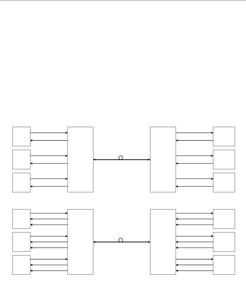
The basic function of the FlexWave URH platform is to transport via fiber optic cable RF
signals form a Base Transceiver Station (BTS) to an antenna interface allowing communication
to a mobile device. Multiple BTS communication paths are allowed over a single URH system.
Diversity receive is supported. A block diagram of the system is shown in Figure 1.
Figure 1. FlexWave URH Block Diagram
The basic function of the FlexWave URH simulcast (point-to-point) platform is to transport, via
fiber optic cable, RF signals form a Base Transceiver Station (BTS) to multiple antenna interfaces
allowing communication to a mobile device. Up to 8 simulcast remotes are supported.
Flexwave
URH
HOST
FWD RF IN
REV RF OUT
BTS 1
Flexwave
URH
REMOTE
ANTENNA
INTERFACE
BTS 1
BTS 2
BTS 3
ANTENNA
INTERFACE
BTS 2
ANTENNA
INTERFACE
BTS 3
NON-DIVERSITY
Flexwave
URH
HOST
FWD RF IN
REV RF OUT
BTS 1
Flexwave
URH
REMOTE
ANTENNA
INTERFACE
BTS 1
BTS 2
BTS 3
ANTENNA
INTERFACE
BTS 2
ANTENNA
INTERFACE
BTS 3
DIVERSITY
REV DIV RF OUT
FWD RF OUT
REV RF IN
REV DIV RF IN
FWD RF OUT
REV RF IN
REV DIV RF IN
FWD RF OUT
REV RF IN
REV DIV RF IN
FWD RF IN
REV RF OUT
REV DIV RF OUT
FWD RF IN
REV RF OUT
REV DIV RF OUT
FWD RF IN
REV RF OUT
FWD RF IN
REV RF OUT
FWD RF OUT
REV RF IN
FWD RF OUT
REV RF IN
FWD RF OUT
REV RF IN
22380-A
ADCP-75-348 • Issue 1 • 04/2008
Page 2
© 2008, ADC Telecommunications, Inc.
2 INTRODUCTION
The front access URH Host Unit interfaces with the BTS and performs the analog to digital and
electrical to optical conversions for transport to the URH Remote Units. A typical URH system
consists of a Host Unit (HU) and a Remote Unit (RU).
The HU is designed for maximum RF flexibility to address Carriers changing and evolving
spectrum needs, making the most use of cost efficient resources for serving multiple remotes
such as simulcast architecture and sharing of common functions such as power, control and
management over multiple host units. These features are designed into a compact package that
reduces the amount of overall rack space required within a BTS Hotel. Each host chassis can
support up to eight RUs.
The HU is a three rack-unit high single-unit assembly that mounts in a standard equipment rack.
The RU consists of an outdoor enclosure that houses various electronic components. The RU is
a modular self-contained enclosure. Together the HU and the RU together comprise an URH
system. Various accessory items are also available for use with each system. All items
referenced as “accessory items” are not furnished and must be purchased separately.
3 HOST UNIT DESCRIPTION
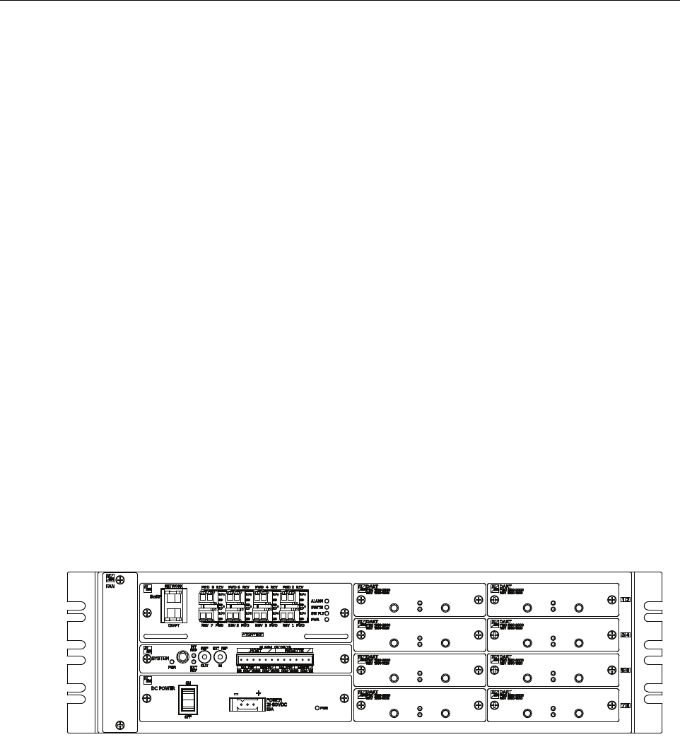
A front view of the HU, shown in
Figure 2
, consists of an electronic circuit board assembly and a
fan assembly that are mounted within a powder-paint coated sheet metal enclosure. The enclosure
provides a mounting point for the circuit board and fan assembly and controls RF emissions. Fan
assembly can be replaced in the field. Host Unit may be upgraded once it is installed to support
additional URH Remote Units. This can be performed without disrupting service.
Figure 2. Front View Host Unit
The HU is designed for use within a non-condensing indoor environment such as inside a wiring
closet or controlled environment cabinet. All controls, connectors, and indicators (except the
grounding point) are mounted on the HU front panel. Current versions of the HU allow vertical
cable guides to be installed over the mounting brackets on either side of the HU.
REV
RF OUT
REV
RF IN
STATUS
PWR
REV
RF OUT
REV
RF IN
STATUS
PWR
REV
RF OUT
REV
RF IN
STATUS
PWR
REV
RF OUT
REV
RF IN
STATUS
PWR
REV
RF OUT
REV
RF IN
STATUS
PWR
REV
RF OUT
REV
RF IN
STATUS
PWR
REV
RF OUT
REV
RF IN
STATUS
PWR
REV
RF OUT
REV
RF IN
STATUS
PWR
22381-A
ADCP-75-348 • Issue 1 • 04/2008
Page 3
© 2008, ADC Telecommunications, Inc.
3.1 Mounting
The HU is intended for rack-mount applications. A pair of reversible mounting brackets is
provided that allow the HU to be mounted in either a 19-inch or 23-inch EIA or WECO
equipment rack. When installed, the front panel of the HU is flush with the front of the rack.
Screws are provided for securing the HU to the equipment rack.
3.2 SeRF Card
3.2.1 Network Interface Connection
SeRF front panel has an Ethernet port allowing interface communication with the internal
processor and transfer of data to the optical protocol allowing IP transport between the HU and
the remote(s). The network interface allows the HU to be controlled through a network.
Network interface connection between the HU and the network is supported by a RJ-45 jack 10/
100Base-T (IEEE802.3 compliant) with integrated green ACTIVITY and LINK LEDs. The
Ethernet port supports a maximum cable length of 100 meters (328 feet) to a hub or back-to-
back nodes. CAT5 or better cable should be used when making this connection. The Ethernet
connection should not be connected to an Ethernet circuit used outside the building.
1. The IEEE Specification for Ethernet 100BaseT requires that two twisted pairs be used and that
one pair is connected to pins 1 and 2, and that the second pair is connected to pins 3 and 6.
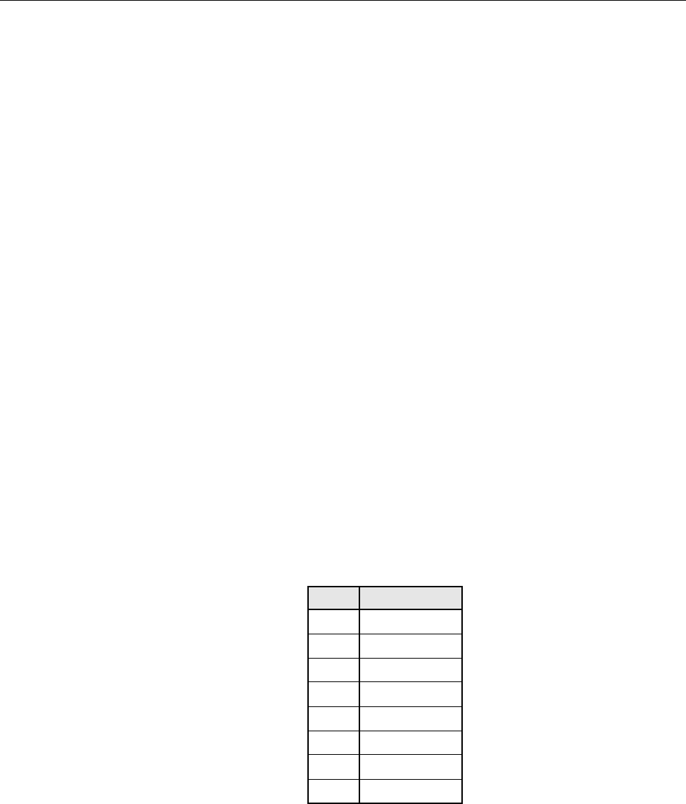
2. Pinout information is shown in Table 1. See Figure 3 for RJ45 connector wiring
information.
Table 1. 100BaseT Ethernet RJ45 Connector
PIN # DESCRIPTION
1TRD0+
2TRD0–
3TRD1+
4TRD2+
5TRD2–
6TRD1–
7TRD3–
8TRD3+

ADCP-75-348 • Issue 1 • 04/2008
Page 4
© 2008, ADC Telecommunications, Inc.
Figure 3. RJ45 Connector Wiring
3.2.2 Craft Interface Connection
SeRF front panel provides a craft port that can be used to provision remote units through the
optical protocol supported by a single RJ-45 connector. The Craft connector provides an
Ethernet interface.
Craft interface connection between the HU and the network is supported by a RJ-45 jack 10/
100Base-T (IEEE802.3 compliant) with integrated green ACTIVITY and LINK LEDs. The
Ethernet port supports a maximum cable length of 100 meters (328 feet) to a hub or back-to-
back nodes. CAT5 or better cable should be used when making this connection.
1. The IEEE Specification for Ethernet 100BaseT requires that two twisted pairs be used and that
one pair is connected to pins 1 and 2, and that the second pair is connected to pins 3 and 6.
2. Pinout information is shown in Table 1. See Figure 3 for RJ45 connector wiring
information.
3.2.3 Optical Interface
Optical connections between the HU SeRF card and the RU are supported through Small Form-
factor Pluggable (SFP) transceivers. The optical interfaces are standard single-mode duplex LC
(flat polished UPC). There are 8 duplex optical interfaces, one for each simulcast remote.
3.3 DART Card
The host DART provides the interface between base station equipment and the SeRF. It is a
band specific assembly and exists in the following versions:
• Cellular
•SMR 800
•SMR 900
•PCS
The following features and capabilities are available on the DART Card:
• Amplifies, down-converts, filters and digitizes from a 1.5MHz to 35MHz band of the
incoming RF signal
RJ-JACK
PIN 1
PIN 8
11899-A

ADCP-75-348 • Issue 1 • 04/2008
Page 5
© 2008, ADC Telecommunications, Inc.
• Converts incoming digital signal to analog, filters, amplifies and up-converts
• Provides bi-directional interface between parallel digital RF (to D/A and from A/D) and
Serial RF (SeRF) to/from SeRF board
• Performs digital up/down conversion and adjustable delay processing
• Non-contiguous bands and receive diversity is implemented with multiple DART Cards
3.3.1 RF Signal Connections
The RF signal connections between the HU DART cards and the BTS are supported through
two (FWD RF IN and REV RF OUT) QMA-Type female connectors. One connector is used for
the forward path RF signal. The other connector is used for the reverse path RF signal. In some
installations, it may be necessary to install a Conditioning Panel and/or Duplexing Panel
(accessory items) to support the interface between the HU and the BTS. The HU should be as
close as possible to the BTS to minimize cable losses.
3.4 System Card
The System Interface Card gives additional front panel space for the SeRF card. The System
Card front panel also provides connections for alarm outputs, 10 MHz output, and status LEDs.
This card may be used to provide a 10 MHz clock reference to which the SeRF's Master clock is
frequency locked from the internal crystal oscillator. When the internal clock is not used the
clock can be obtained from an external 10 MHz input.
3.5 Power Supply
HU is powered by a modular DC to DC power supply located on the lower left side of the
chassis. An On/Off switch is provided on the HU power supply module front panel.
HU is powered by ± 20 to ± 60 VDC power (nominal ± 24 or ± 48 VDC), power is fed to the HU
through a connector located on the front of the module. Power to the HU must be supplied
through a fuse panel (available separately). Each HU must be protected with a fuse.
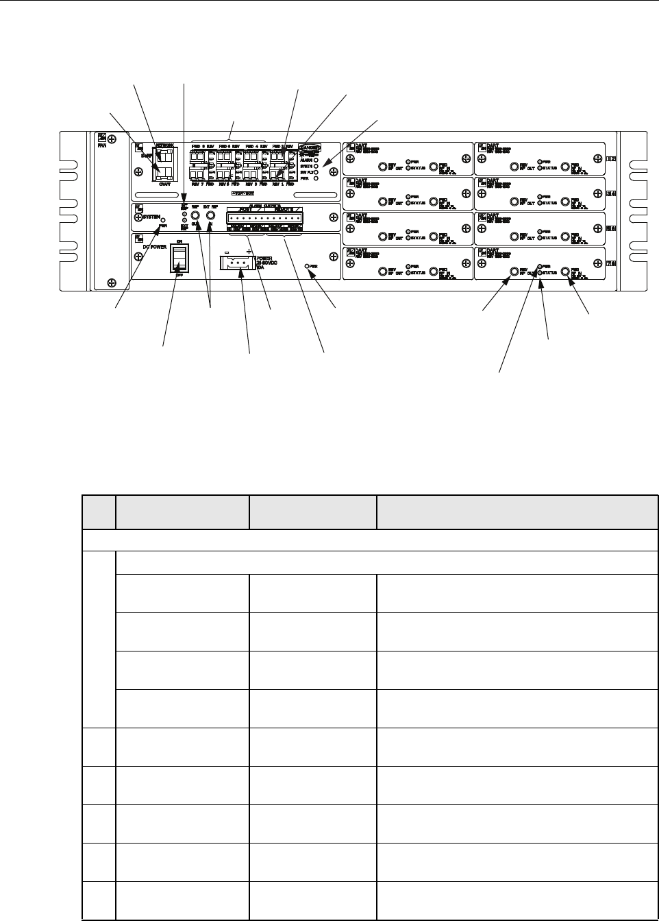
3.6 User Interface
The HU user interface consists of the various connectors, switches, terminals, and LEDs that are
provided on the HU front panel. The HU user interface points are indicated in Figure 4 and
described in Table 2.
ADCP-75-348 • Issue 1 • 04/2008
Page 6
© 2008, ADC Telecommunications, Inc.
Figure 4. Host Unit User Interface
Table 2. Host Unit User Interface
REF
NO
USER INTERFACE
DESIGNATION DEVICE FUNCTIONAL DESCRIPTION
SeRF CARD
1SeRF Card LEDs
ALARM GREEN
RED
No alarms
Alarms present
SYNTH GREEN
RED
Locked
Unlocked
SW FLT GREEN
RED
Software operating OK
Software fault present
PWR GREEN
OFF
Power OK and operating properly
No power present
2PORT 1 or FWD LC connector
(single-mode)
Output connection point for the forward path
optical fiber.
3PORT 2 or REV LC connector
(single-mode)
Input connection point for the reverse path pri-
mary optical fiber.
4PORT 3 –8 LC connector
(single-mode)
Input/output connection points for the remaining
optical fibers.
5NETWORK RJ-45 jack (female) Connection point for the NETWORK interface
input cable.
6CRAFT RJ-45 jack (female) Connection point for the CRAFT interface input
cable.
(6) CRAFT
INTERFACE
(5) NETWORK
INTERFACE
(4) OPTICAL PORT
CONNECTORS 3 - 8
(2) PORT 1
FWD
CONNECTOR
(3) PORT 2
REV
CONNECTOR
(1) SeRF CARD
ALARM LEDS
(10) SYSTEM CARD
POWER LED
INDICATOR
(8) DC POWER
ON/OFF SWITCH
(13) REF LED
INDICATORS
(14 & 15)
REF OUT
AND IN JACKS
(11) HOST
ALARM
OUTPUTS
(9) POWER
CONNECTOR
(12) REMOTE
ALARM
OUTPUTS
(7) POWER
LED INDICATOR
(18) REV RF
OUT JACK
(17) DART STATUS
LED INDICATOR
(16) DART POWER
LED INDICATOR
(19) FWD RF
IN JACK
22382-B

ADCP-75-348 • Issue 1 • 04/2008
Page 7
© 2008, ADC Telecommunications, Inc.
4 HOST UNIT ACCESSORIES
This section provides a brief description of various accessory items that are available separately.
The accessory items may or may not be required depending on the application.
POWER SUPPLY
7PWR (LED) GREEN
RED
DC Power Supply OK
DC Power Supply Fault
8ON/OFF On/Off rocker switch Provides HU power on/off control.
9POWER 20–60 VDC Three position
connector
Connection point for the DC power wiring.
SYSTEM CARD
10 PWR (LED) GREEN
RED
System Card Power Supply OK
System Card Power Supply Fault
11 ALARM OUTPUTS
HOST
Twelve position ter-
minal block. Screw-
type terminal
connector (14–26
AWG)
Connection points for an major and minor dry
alarm contacts. Includes normally open (NO),
normally closed (NC), and common (COM) wir-
ing connections.
12 ALARM OUTPUTS
REMOTE
13 INT REF (LED)
EXT REF (LED)
GREEN
OFF
GREEN
OFF
Internal 10 MHz reference selected as the as Ref-
erence Clock.
Internal 10 MHz reference not selected.
External 10 MHz reference selected as the as
Reference Clock.
External 10 MHz reference not selected
14 REF OUT QMA-Type female
RF coaxial connector
Ref Clock
15 EXT REF IN QMA-Type female
RF coaxial connector
Ref Clock
DART CARD
16 PWR (LED) GREEN
OFF
Card is powered.
No power present at card.
17 STATUS (LED) GREEN
RED
YELLOW
OK
Fault
Unlocked
18 REV RF OUT QMA-Type female
RF coaxial connector
Output connection point for the primary reverse
path RF coaxial cable.
19 FWD RF IN QMA-Type female
RF coaxial connector
Input connection point for the forward path RF
coaxial cable.
Table 2. Host Unit User Interface, continued
REF
NO
USER INTERFACE
DESIGNATION DEVICE FUNCTIONAL DESCRIPTION
ADCP-75-348 • Issue 1 • 04/2008
Page 8
© 2008, ADC Telecommunications, Inc.
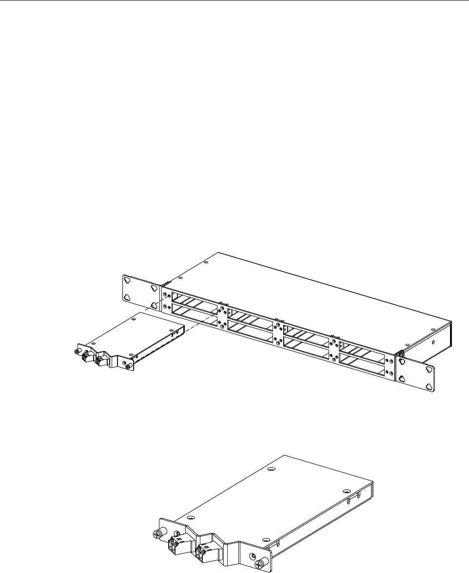
4.1 Wavelength Division Multiplexer System
The Wavelength Division Multiplexer (WDM) system is an accessory product that is used when
it is desirable or necessary to combine the forward and reverse path optical signals from one
URH system onto a single optical fiber. Each WDM system consists of a host module and a
remote module.
Both the host unit WDM module and the RU WDM module consist of a bi-directional wavelength
division multiplexer. The host unit WDM module is mounted within a powder-paint coated sheet
metal enclosure. A straight LC-type optical connector port is provided for connecting the forward/
reverse path optical fiber to the WDM module. A pair of pigtail leads with LC-type connectors are
provided for connecting the WDM module to the forward and reverse path optical ports on the HU
SeRF card.
The WDM host module mounting shelf and host module are shown in Figure 5. The WDM
module is shown in Figure 6.
Figure 5. WDM Host Module and Host Module Mounting Shelf
Figure 6. Host Unit WDM Module
22390-A
22391-A

ADCP-75-348 • Issue 1 • 04/2008
Page 9
© 2008, ADC Telecommunications, Inc.
5 SPECIFICATIONS
The specifications for the host unit are provided in Table 3.
6 INSTALLATION
This section provides the installation procedures for the HU and the WDM host module
(accessory item). Installation of the RU components may proceed separately from installation of
the HU.
6.1 Before Starting Installation
Before beginning the installation, review the system design plan with the system engineer.
Make sure each equipment installation site is identified and located and all cable runs are
mapped out. Also identify all tools and materials that are required to complete the installation.
Table 3. Host Unit Nominal Specifications
PARAMETER SPECIFICATION REMARKS
Dimensions (H×W×D) 5.17 × 17.26 × 9.5 inches
(131.3 × 438.4 × 241.3 mm)
Dimension for width does not
include the mounting brackets
which can be installed for either
19- or 23-inch racks.
Mounting 19- or 23-inch rack EIA or WECO
Weight 20 lbs. (9.1 kg)
Weather resistance Indoor installation only Environmentally controlled out-
door cabinet.
Operating temperature 0º to 55º C (32º to 131º F)
Storage temperature –40º to 70º C (–40º to 158ºF)
Humidity 10% to 90% No condensation
Optical ports SFP pluggable transceivers LC (UPC)
Transceivers Fujitsu FIM32151 or FIM32141 Available from ADC
External alarm connector Screw-type terminals NO, COM, and NC relay contacts
Voltage input
DC Power ±20 – ±60 VDC
Power consumption 320 Watts (Maximum) 202 Watts nominal
Current rating 4.2 Amps
7.2 Amps
At –48VDC
At +28VDC
RF coaxial cable connectors 50 ohm QMA – type (female) 50 ohms input/output impedance
Network and Craft connectors RJ–45 jack
Reliability at 25ºC MTBF 100,000 hours Including fans

ADCP-75-348 • Issue 1 • 04/2008
Page 10
© 2008, ADC Telecommunications, Inc.
6.1.1 Tools and Materials
The following tools are required to complete the procedures in this section:
• Box cutter
• Pencil or scribe
• Medium size flat-bladed screwdriver
• Phillips screwdriver (#2)
•Pliers
• Wire cutters
• Wire stripper
• Tool kit for attaching QMA-Type male connectors to coaxial cable
• Multimeter
•Optical power meter
The following materials are required to complete the procedures in this section:
• #18 AWG (1.0 mm) insulated stranded copper wire (for chassis grounding wire)
• #18 AWG (1.0 mm) red and black insulated copper wire (for DC power wires)
• Category 3 or 5 cable (for external alarm system wires)
• Category 5 cable with RJ45 connectors for the Network and Craft port
• #6 ring terminal (1) for #18 wire (for chassis ground wire connection)
• #6 fork terminals (2) for #18 wire (for DC power wiring connection)
• Single-mode patch cord(s) with LC connectors (1 – 8 depending on the application)
• High performance, flexible, low-loss 50-ohm coaxial cable
• QMA-type male connectors
• Wire ties
6.2 Unpacking and Inspection
This section provides instructions for opening the shipping boxes, verifying that all parts have
been received, and verifying that no shipping damage has occurred. Use the following
procedure to unpack and inspect the HU and any accessories:
Unpack and inspect the various components as follows:
1. Inspect the exterior of the shipping container(s) for evidence of rough handling that may
have damaged the components in the container.
2. Unpack each container while carefully checking the contents for damage and verify with
the packing slip.
3. If damage is found or parts are missing, file a claim with the commercial carrier and notify
ADC Customer Service. Save the damaged cartons for inspection by the carrier.
4. Refer to Section 8 if you need to contact ADC.
5. Save all shipping containers for use if the equipment requires shipment at a future date.
ADCP-75-348 • Issue 1 • 04/2008
Page 11
© 2008, ADC Telecommunications, Inc.
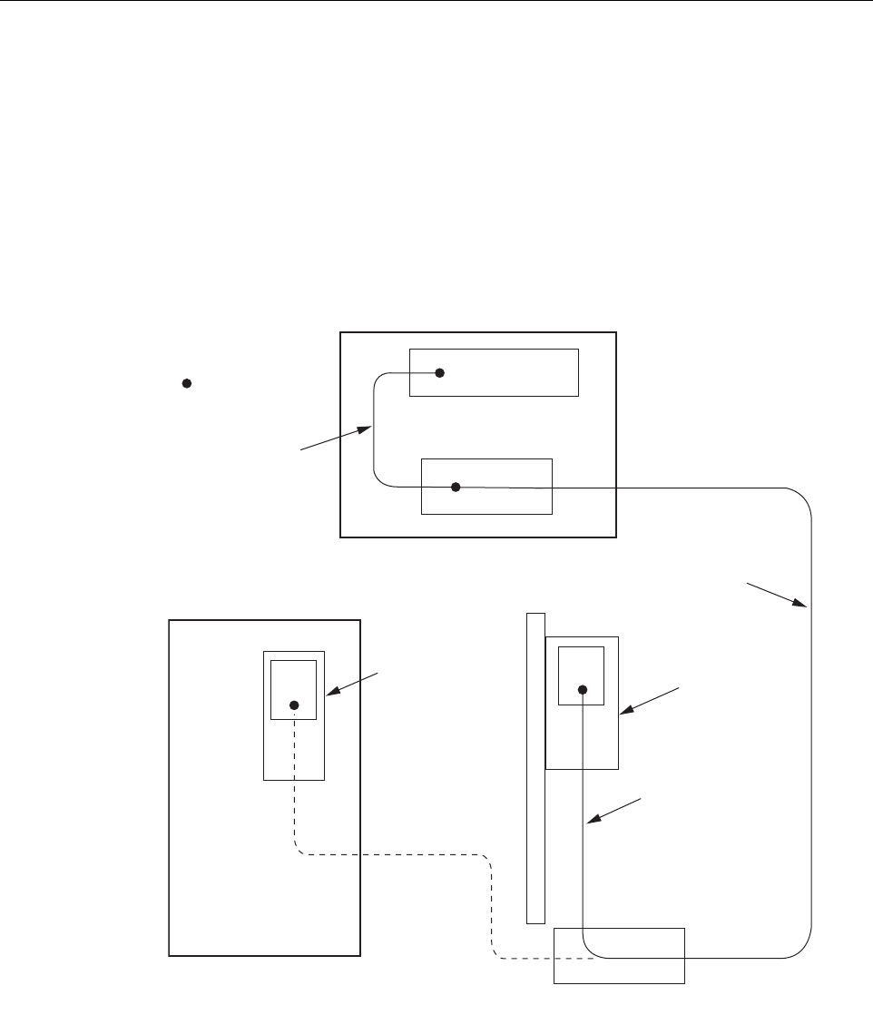
6.3 OSP Fiber Cable Installation Guidelines
The outside plant (OSP) fiber optic cables should be routed between the HU distribution panel
and RU outside plant cabinet and terminated before the equipment is installed. A diagram of a
typical OSP cable routing is shown in Figure 7. At the HU, the OSP cable should be terminated
at a fiber distribution panel and spliced to pigtails. Jumper patch cords may then be used to link
the HU optical ports to the OSP cable terminations. Whenever possible, a guideway such as the
FiberGuide system should be provided to protect the fiber optic patch cords from damage and to
prevent excessive bending. The procedures for connecting the OSP cable optical fibers to the
HU is provided in Section 6.8.
Figure 7. Typical Fiber Optic Cable Routing
HOST UNIT
FIBER DISTRIBUTION
PANEL
OUTDOOR
REMOTE SITE
HOST SITE
PATCH
CORDS
SPLICE
INDOOR/OUTDOOR
QUAD CABLE WITH
PRE-TERMINATED
CONNECTOR
OUTSIDE PLANT
CABLE
URH
REMOTE
UNIT
22383-A
INDOOR
REMOTE SITE
X
TERMINATION
X
URH
REMOTE
UNIT
OUTSIDE PLANT
CABINET
X
ADCP-75-348 • Issue 1 • 04/2008
Page 12
© 2008, ADC Telecommunications, Inc.
6.4 WDM Host Module Mounting Shelf and WDM Host Module Installation Procedure
A bi-directional wavelength division multiplexer (WDM) system is available as an accessory
item for the URH system. If the application does not require the use of a WDM system, skip this
section and proceed to Section 6.5.
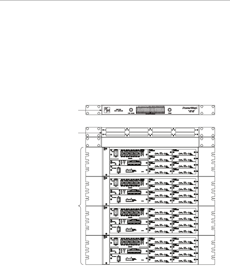
The WDM host module mounting shelf installs in the equipment rack with the HU. Each host
module mounting shelf can hold multiple modules and each host module can support two HU’s.
When multiple HU’s require connection to a WDM system, the host module mounting shelf and
the HU’s should be mounted in the equipment rack as shown in Figure 8. This configuration
allows the pigtail leads from the two host modules to be connected directly to the optical ports
on any one of the four HU’s.
Figure 8. Typical WDM and HU Configuration
The WDM host module mounting shelf may be mounted in either a 19-inch or 23-inch EIA or
WECO equipment rack. Four #12-24 screws are provided for securing the mounting shelf to the
rack. Use the following procedure to install the WDM host module mounting shelf in the
equipment rack and to mount the WDM modules in the WDM host module mounting shelf:
WDM MOUNTING
SHELF
(WITHOUT MODULES)
22392-A
POWERWORX
FUSE PANEL
HOST UNITS
HOST SLACK FIBER STORAGE
ADCP-75-348 • Issue 1 • 04/2008
Page 13
© 2008, ADC Telecommunications, Inc.
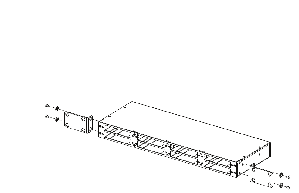
1. The WDM host module mounting shelf is shipped with the mounting brackets installed for
23-inch rack installations. If installing the mounting shelf in a 23-inch rack, proceed to
Step 4. If installing the mounting shelf in a 19-inch rack proceed to Step 2.
2. Remove both mounting brackets from the mounting shelf (requires Phillips screwdriver)
and save screws for reuse.
3. Reinstall both mounting brackets so the short side of the bracket is flush with the front
panel as shown in as shown in Figure 9. Use the screws removed in Step 2 to attach the
new brackets to the mounting shelf.
Figure 9. Installing the Replacement Mounting Brackets
4. Position the mounting shelf in the designated mounting space in the rack (per system
design plan) and then secure the mounting brackets to the rack using the four #12-24
machine screws provided.
5. Install each WDM host module in the mounting shelf. A rail on the side of the module fits
into a guide within the mounting.
6. Secure each host module to the mounting shelf by twisting the handle on each quarter-turn
fastener 90º.
7. Carefully store the pigtail leads from each host module. The routing and connection
procedures for the pigtails are provided in Section 6.8.
6.5 HU Mounting Procedure
The HU may be mounted in either a 19-inch or 23-inch EIA or WECO equipment rack. Both
US standard and metric machine screws are included for rack mounting the HU. When loading
the HU in a rack, make sure the mechanical loading of the rack is even to avoid a hazardous
condition such as a severely unbalanced rack. The rack should safely support the combined
weight of all the equipment it holds. In addition, maximum recommended ambient temperature
for the HU is 55º C (131º F). Allow sufficient air circulation or space between units when the
HU is installed in a multi-rack assembly because the operating ambient temperature of the rack
environment might be greater than room ambient.
22393-A
ADCP-75-348 • Issue 1 • 04/2008
Page 14
© 2008, ADC Telecommunications, Inc.
Use the following procedure to install the HU in the equipment rack:
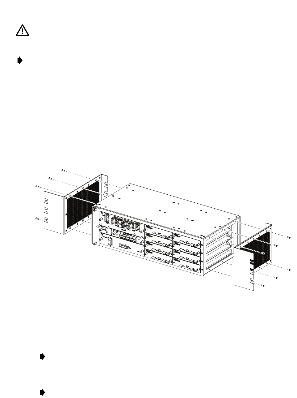
1. The HU is shipped with the mounting brackets installed for 19-inch rack installations. If
mounting the HU in a 19-inch rack, proceed to Step 4. If mounting the HU in a 23-inch
rack, proceed to Step 2.
2. Remove both mounting brackets from the HU (requires TORX screwdriver with T20 bit)
and save screws (six-screws on each side) for reuse.
3. Reinstall both mounting brackets so the short side of the bracket is flush with the HU front
panel as shown in Figure 10. Use the screws removed in Step 2 to re-attach the brackets to
the HU chassis.
Figure 10. Installing the Mounting Brackets for 23-Inch Rack Installations
4. Position the HU in the designated mounting space in the rack (per system design plan) and
then secure (but do not tighten) the HU to the rack using the four machine screws provided
(use #12-24 or M6 x 10 screws, whichever is appropriate).
5. Locate two vertical cable guides, not provided with the HU.
Warning: Wet conditions increase the potential for receiving an electrical shock when
installing or using electrically powered equipment. To prevent electrical shock, never install or
use electrical equipment in a wet location or during a lightning storm.
Note: To insure that all optical connectors remain dust-free during installation, leave all dust
caps and dust protectors in place until directed to remove them for connection.
Note: Provide a minimum of 3 inches (76 mm) of clearance space on both the left and
right sides of the HU for air intake and exhaust.
Note: A vertical cable guide kit is available separately as an accessory.
INSTALL MOUNTING
BRACKETS AS SHOWN FOR
INSTALLATION IN 23-INCH RACKS
22394-A
ADCP-75-348 • Issue 1 • 04/2008
Page 15
© 2008, ADC Telecommunications, Inc.
6. Back out the HU mounting screws just enough to provide clearance for installation of the
cable guides.
7. Slide each cable guide into position for installation and then securely tighten the
corresponding mounting screws.
6.6 Chassis Ground Connection
A stud is provided on the rear side of the chassis for connecting a grounding wire to the chassis.
Use the following procedure to connect the grounding wire to the chassis and to route the
grounding wire to an approved earth ground source.
1. Obtain a length of #18 AWG (1.00 mm) insulated stranded copper wire for use as a
chassis grounding wire.
2. Terminate one end of the wire with a ring terminal.
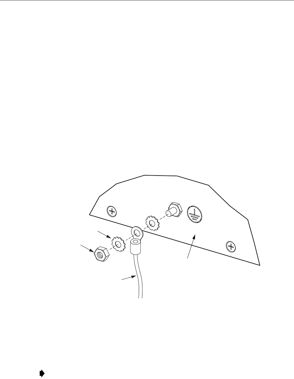
3. Locate the chassis ground stud at the rear of the HU as shown in Figure 11.
4. Attach the ring end of the wire to the chassis ground stud (see Figure 11).
Figure 11. Chassis Ground Stud
5. Route the free end of the chassis grounding wire to an approved (per local code or
practice) earth ground source.
6. Cut the chassis grounding wire to length and connect it to the approved ground source as
required by local code or practice.
Note: Be sure to maintain reliable grounding. Pay particular attention to ground source
connections.
22395-A
REAR OF
CHASSIS
STAR
WASHER
HEX
NUT
GROUND
WIRE

ADCP-75-348 • Issue 1 • 04/2008
Page 16
© 2008, ADC Telecommunications, Inc.
6.7 Coaxial Cable Connections
The RF interface between the HU DART card and the EBTS/BTS is supported through two type
QMA female connectors mounted on each DART front panel. One connector provides the
coaxial cable connection for the forward path (downlink) signal and the other connector
provides the coaxial cable connection for the reverse path (uplink) signal.
In most installations, it is usually necessary to insert an
external attenuator
into the forward path
link between the HU and the BTS. A signal level that is greater than –9 dBm will overdrive and
possibly damage the HU receiver. Before completing the forward path connection at the BTS,
verify that the composite forward path RF signal level at the HU is between
–25 and +5 dBm
.
The HU should be mounted as close as possible to the EBTS/BTS to minimize cable losses. Use
the following procedure to route and connect the forward and reverse path coaxial cables to the
HU DART cards:
1. Obtain the required lengths of high performance, flexible, low loss 50-ohm coaxial
communications cable (RG-400 or equivalent) for all coaxial connections.
2. Route the forward and reverse path coaxial cables between the HU and the BTS interface
(per system design plan) and cut to the required length. Allow sufficient slack for dressing
and organizing cables at the HU and for installing an external attenuator in the forward
path link.
3. Terminate each cable with an QMA-Type male connector following the connector
supplier’s recommendations.
4. If required, install an external attenuator in the forward path.
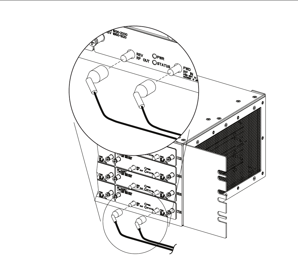
5. Connect the forward path cable to the FWD RF IN connector on the HU DART front
panel as shown in Figure 12.
6. Connect the reverse path cable to the REV RF OUT connector on the HU DART front
panel (see Figure 12).
7. Repeat this procedure for the remaining DART cards in the HU.
8. Dress and secure cables at the right side of the HU.
9. Complete all remaining coaxial connections as specified in the system design plan.
Note: The composite forward path RF signal level at the HU must be between –25 and
+5 dBm. Do not connect the forward path cable until the composite forward path RF
signal level is measured and the amount of external attenuation required is determined.
ADCP-75-348 • Issue 1 • 04/2008
Page 17
© 2008, ADC Telecommunications, Inc.
Figure 12. Forward and Reverse Path Coaxial Cable Connections
6.8 Optical Connections
The optical interface between the HU and the RU is supported by optical ports. Each optical
port consists of an SFP with LC optical transceivers mounted on the SeRF card front panel.
Each FWD port provides an optical connection for the forward path (downlink) signal. Each
REV port provide an optical connection for the reverse path (uplink) signal. Each REV port can
also provide the optical connection for the diversity reverse path (uplink) signal.
The optical connections are dependent on whether or not a WDM host module (accessory) is
installed:
• If the installation does not include a WDM module, proceed to Section 6.8.1 for the
optical connections procedure.
• If the installation includes a WDM module, proceed to Section 6.8.2 for the optical
connections procedure.
22411-A

ADCP-75-348 • Issue 1 • 04/2008
Page 18
© 2008, ADC Telecommunications, Inc.
6.8.1 Optical Connections Without WDM System
Use the following procedure to connect the optical fibers when there is no WDM installed with the
HU:
1. Obtain two patch cords that are of sufficient length to reach from the HU to the fiber
distribution panel.
2. Designate one of the patch cords as the forward path link and the other as the reverse
path link and attach an identification label or tag next to the connector.
3. Remove the dust caps from the HU SeRF SFP optical ports and from the patch cord
connectors that will be connected to the SeRF SFP optical ports.
4. Clean each patch cord connector following the patch cord supplier’s recommendations.
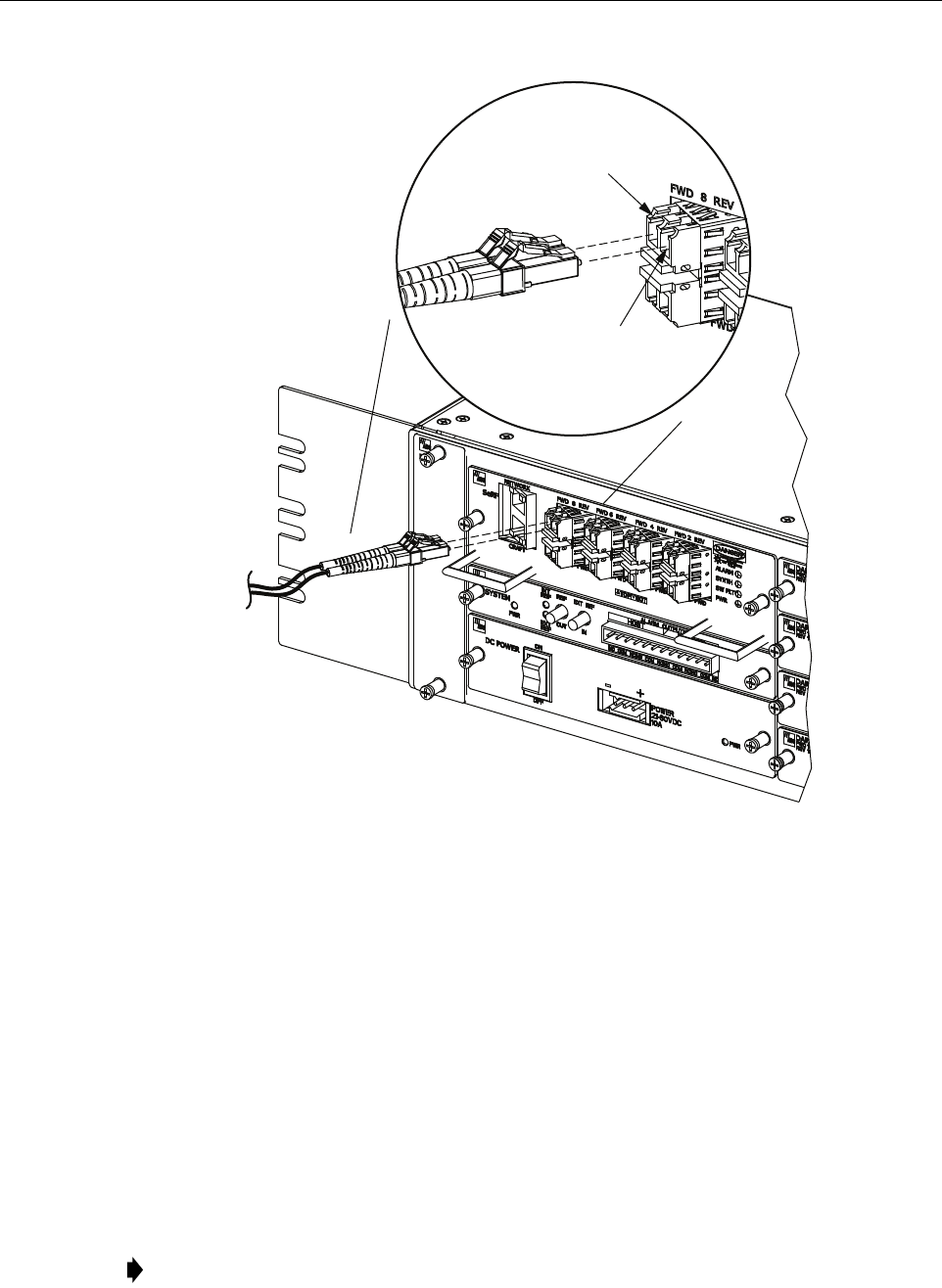
5. Insert each patch cord connector into the appropriate optical port as shown in Figure 13
and as specified by the following:
PORT 1 FWD - Forward path patch cord
PORT 1 REV - Reverse path patch cord
6. Route the patch cords from the HU to the fiber distribution panel.
7. At the fiber distribution panel, identify the OSP cable optical fiber terminations that
correspond to the forward and reverse paths.
8. Remove the dust caps from the OSP cable optical fiber adapters and from the patch cord
connectors.
9. Clean each patch cord connector (follow patch cord supplier’s recommendations) and then
mate the connector with the appropriate OSP cable adapter.
Danger: This equipment uses a Class 1 Laser according to FDA/CDRH rules. Laser radiation
can seriously damage the retina of the eye. Do not look into the ends of any optical fiber. Do not
look directly into the optical transmitter of any unit or exposure to laser radiation may result.
An optical power meter should be used to verify active fibers. A protective cap or hood MUST
be immediately placed over any radiating transmitter or optical fiber connector to avoid the
potential of dangerous amounts of radiation exposure. This practice also prevents dirt particles
from entering the connector.
Note: To protect the optical receivers, insert a 15 dB attenuator in each optical path. When
the system is turned-up and tested, the attenuator may be resized or removed.
Caution:
Improper handling can damage fiber optic cables. Do not bend fiber optic cable more
sharply than the minimum recommended bend radius specified by the cable manufacturer. Do not
apply more pulling force to the cable than specified.
Note: The HU optical adapters are angled to the left. Therefore, always route patch cords
to the HU from the left side of the rack. Routing patch cords to the HU from the right may
exceed the bend radius limitations for the optical fiber.
ADCP-75-348 • Issue 1 • 04/2008
Page 19
© 2008, ADC Telecommunications, Inc.
Figure 13. Fiber Optic Cable Connections To Host Unit
10. Repeat this procedure for the remaining SeRF SFPs in the HU.
11. Store any excess patch cord slack at the fiber distribution panel or storage panel.
6.8.2 Optical Connections For Systems With a WDM
Use the following procedure to connect the optical fibers when a WDM module is installed with
the HU:
1. Obtain a patch cord that is of sufficient length to reach from the WDM module to the fiber
distribution panel.
2. Remove the dust cap from WDM Port or Port 4 on the WDM module and from the patch
cord connector that will be connected to the WDM module.
Note: WDM module ports are labeled FWD, REV, TEST, and WDM.
22410 -A
PORT 8 FWD
(FORWARD PATH)
PORT 8 REV
(REVERSE PATH)
ADCP-75-348 • Issue 1 • 04/2008
Page 20
© 2008, ADC Telecommunications, Inc.
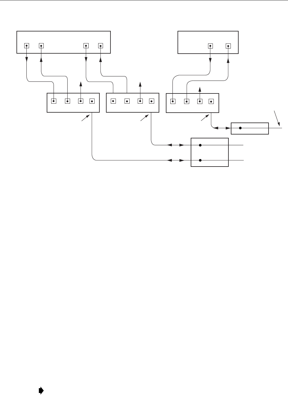
Figure 14. Fiber Optic Connections To WDM Module
3. Clean the patch cord connector (follow patch cord supplier’s recommendations).
4. Insert the connector into the WDM module optical WDM port (port 4).
5. Route the patch cord from the WDM to the fiber distribution panel or storage panel.
6. Identify the OSP cable optical fiber termination that corresponds to the RU.
7. Remove the dust cap from the OSP cable optical adapter and from the patch cord
connector.
8. Clean the patch cord connector (follow patch cord supplier’s recommendations) and then
mate the connector with the appropriate OSP cable adapter.
9. Store any excess patch cord slack at the fiber distribution panel.
10. Obtain two patch cords that are of sufficient length to reach from the WDM module to the HU.
11. Designate one of the patch cords as the forward path link and the other as the reverse
path link and attach an identification label or tag next to the connector.
12. Remove the dust caps from the HU SeRF SFP optical ports and from the patch cord
connectors that will be connected to the SeRF SFP optical ports.
13. Clean each pigtail connector (follow the procedures provided with the WDM module) and
then insert the connector into the appropriate optical port on the HU as shown in Figure 13
and as diagramed in Figure 14.
Note: To protect the optical receivers, insert a 15 dB attenuator in each optical path. When
the system is turned-up and tested, the attenuator may be resized or removed.
FIBER DISTRIBUTION
PANEL (FDP)
X
X
HOST UNIT 1
PORT 8
FWD
PORT 8
REV
REVERSE
PATH
FORWARD
PATH
WAVELENGTH
DIVISION
MULTIPLEXERS
1234
PORT 1
FWD
PORT 1
REV
HOST UNIT 2
REVERSE
PATH
FORWARD
PATH
22416-A
TO/FROM
REMOTE UNIT 1
TO/FROM
REMOTE UNIT 1
HOST UNIT 1
(BI-DIRECTIONAL FIBER
LINK WITH REMOTE UNIT)
HOST UNIT 1
(BI-DIRECTIONAL FIBER
LINK WITH REMOTE UNIT)
PORT 1
FWD
PORT 1
REV
REVERSE
PATH
FORWARD
PATH
1234
TESTTEST
1234
TEST
FIBER DISTRIBUTION
PANEL (FDP)
X
TO/FROM
REMOTE UNIT 2
HOST UNIT 2
(BI-DIRECTIONAL FIBER
LINK WITH REMOTE UNIT)
ADCP-75-348 • Issue 1 • 04/2008
Page 21
© 2008, ADC Telecommunications, Inc.
6.9 EXT REF Connections
EXT REF connections between multiple HU’s is supported through two QMA type female
connectors mounted on the System card. One of the jacks is designated as the IN port and the
other jack is designated as the OUT port. The EXT REF interface allows HU’s to be connected
together (in daisy-chain fashion) and clocked through a single source. Use the following
procedure to connect EXT REF interface cables between multiple HU’s:
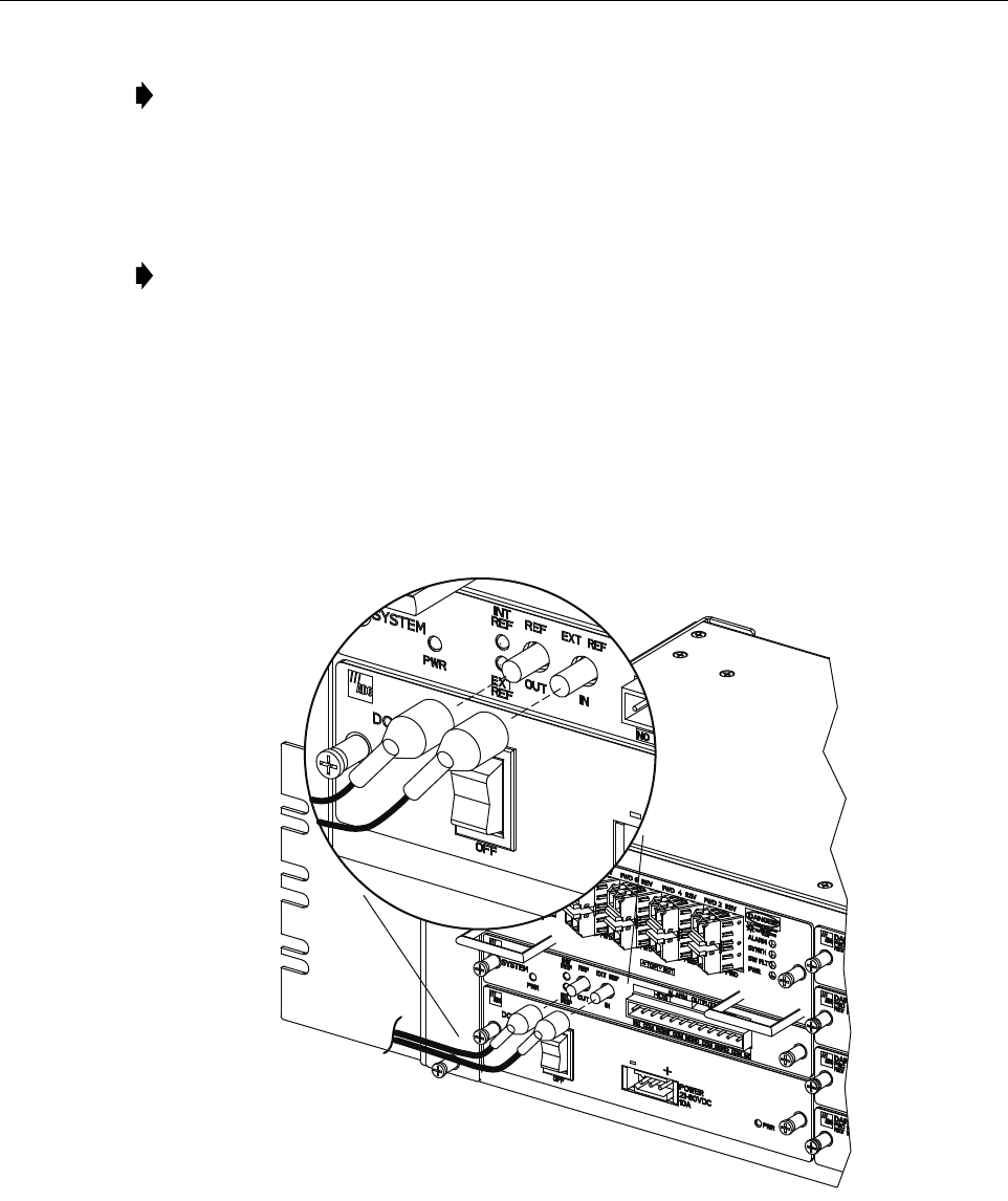
1. Connect one end of the EXT REF interface cable (accessory) to either the IN or OUT port
on HU #1 as shown in Figure 15.
Figure 15. EXT REF Connections
2. Route the EXT REF interface cable to HU #2 and connect the cable’s free end to the port
that is the logical opposite of the EXT REF interface connection at HU #1.
Note: The HU SeRF SFP optical adapters are angled to the left. Therefore, pigtails should
always be routed to the HU from the left side of the rack. Routing pigtails to the HU from
the right side of the rack may exceed the bend radius limitations for the optical fiber.
Note: When using the 10 MHz external reference clock the signal must be connected to
the HU before enabling the clock source in the software.
22407-A
ADCP-75-348 • Issue 1 • 04/2008
Page 22
© 2008, ADC Telecommunications, Inc.
3. If a third HU will be connected to the network, connect a second EXT REF interface cable
to the remaining network port on HU #2.
4. Route the second EXT REF interface cable to HU #3 and connect the cable’s free end to
the port that is the logical opposite of the EXT REF interface connection at HU #2.
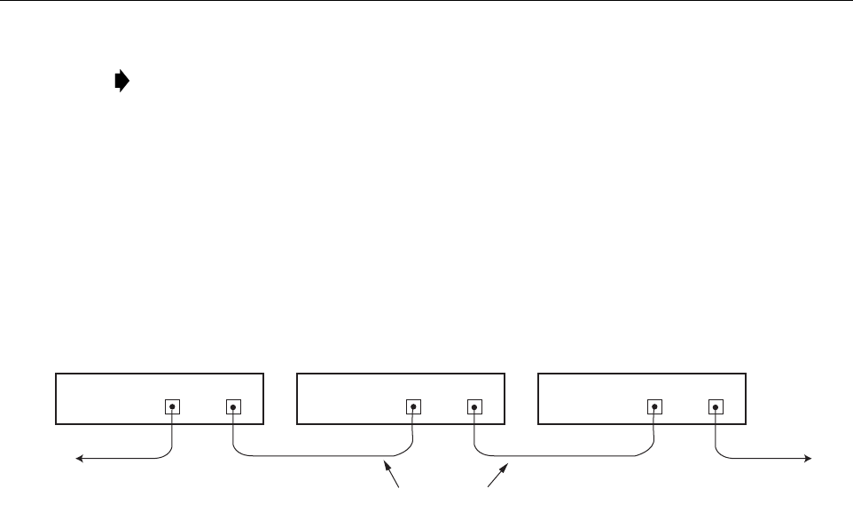
5. Repeat steps 3 and 4 for each additional HU that is added to the network. A diagram of
typical EXT REF interface connections is shown in Figure 16.
Figure 16. Configuring EXT REF Connections with Multiple Host Units
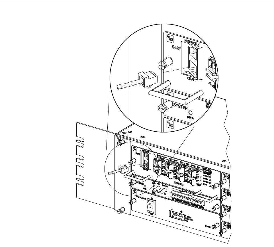
6.10 Computer Connection (CRAFT)
The service interface connection between the HU and the computer is supported by a single RJ-
45 connector. Use the following procedure to install the service interface cable:
1. Connect one end of the service interface cable (accessory) to the CRAFT port as shown in
Figure 17.
2. Route the service interface cable to the computer and connect the free end of the cable to
the computer’s port. Refer to the user manual provided with the computer to locate and
configure the specified port.
Note: Connect OUT to IN and IN to OUT. If connected to a EXT REF OUT port at HU
#1, connect to the EXT REF IN port at HU #2. If connected to a EXT REF IN port at HU
#1, connect to a EXT REF OUT port at HU #2.
HOST UNIT 3 HOST UNIT 2 HOST UNIT 1
OUT EXT IN NET IN NET OUT NET IN NET OUT
22414-A
COAXIAL
INTERFACE CABLES
TO NEXT HOST UNIT
(NOTE: LAST HOST HAS NO
CONNECTION AT EXT OUT)
OUT EXT IN OUT EXT IN
REF CLOCK
INPUT
ADCP-75-348 • Issue 1 • 04/2008
Page 23
© 2008, ADC Telecommunications, Inc.
Figure 17. Craft Interface and Network Interface Connections
6.11 Network Connection
A network connection between the HU and the network is used to monitor and configure the
FlexWave URH system through a single IP connection. Use the following procedure to install
the network interface cable:
1. Connect one end of the cable (accessory) to the NETWORK port as shown in Figure 17.
2. Route the cable to the computer and connect the free end of the cable to the computer’s
port. Refer to the user manual provided with the computer to locate and configure the
specified port.
22403-A
RJ-45
CONNECTOR
DETAIL

ADCP-75-348 • Issue 1 • 04/2008
Page 24
© 2008, ADC Telecommunications, Inc.
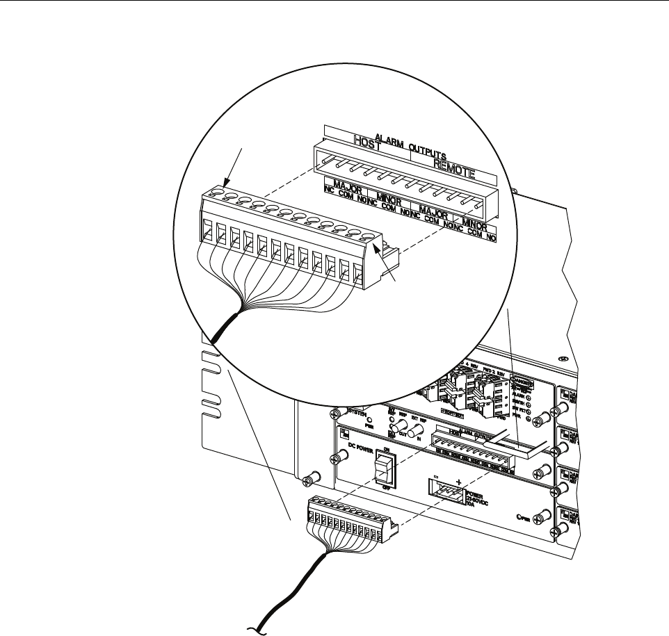
6.12 System Alarm System Connections
The alarm interface between the HU and an alarm system is supported by twelve-terminal plug
(with screw-type terminals) that connects to a receptacle mounted on the HU System card front
panel. The terminal plug provides connections to normally open (NO) and normally closed
(NC) dry type alarm contacts for both major and minor alarms. A category 3 or 5 cable is
typically used to connect the HU System card to the alarm system. Use the following procedure
to install the alarm wiring and connect it to the HU:
1. Obtain the required length of category 3 or 5 cable.
2. Route the cable between the HU System card and the alarm system (if not already routed)
and then cut to the required length. Allow sufficient slack for dressing and organizing the
cable at the HU.
3. Strip back the outer cable sheath and insulation to expose the wires at both ends of the
cable and strip back 0.2 inches (5 mm) of insulation from each wire.
4. Connect the Major alarm wire pair to the MAJOR COM/NC or MAJOR COM/NO
terminals (whichever is required by the alarm system) on the HU System card alarm
terminal connector (supplied with HU System card) as shown in Figure 18.
5. Connect the Minor alarm wire pair to the MINOR COM/NC or MINOR COM/NO
terminals (whichever is required by the alarm system) on the HU System card alarm
terminal connector (see Figure 18 and Table 4).
6. Connect the Major and Minor alarm wire pairs to the appropriate terminals on the external
alarm system.
7. Dress and secure cable per standard industry practice.
Table 4. System Card Alarm Pin Designations
PIN DESCRIPTION
1Host Minor Normally Closed
2Host Minor Common
3Host Minor Normally Open
4Host Major Normally Closed
5Host Major Common
6Host Major Normally Open
7Remote Minor Normally Closed
8Remote Minor Common
9Remote Minor Normally Open
10 Remote Major Normally Closed
11 Remote Major Common
12 Remote Major Normally Open
ADCP-75-348 • Issue 1 • 04/2008
Page 25
© 2008, ADC Telecommunications, Inc.
Figure 18. Alarm System Connections
6.13 Power Connections
HU is powered by a modular power supply located on the lower left side of the chassis. An On/
Off switch is provided on the HU power supply module front panel.
6.13.1 DC Power Connections
The HU is powered by ± 20 to 60 VDC power (nominal ± 24 or ± 48 VDC), install DC Power
Supply in the lower left side of the HU chassis. Secure in place by turning screws clock-wise
until tight.
22406-A
PIN 12
PIN 1

ADCP-75-348 • Issue 1 • 04/2008
Page 26
© 2008, ADC Telecommunications, Inc.
A three position terminal block is provided for connecting the power wires. The power is fed to
the HU Power Supply module through a connector located on the front of the unit. Power to the
HU must be supplied through a fuse panel such as the 20 position PowerWorx GMT Fuse Panel
(available separately) and the power must be protected with a 15 Amp GMT fuse.
Use the following procedure to install the power wiring:
1. Obtain the items listed below:
• Wire stripper and screwdriver
•Wire,
#18 AWG (1.00 mm) red and black insulated copper wire
. Recommended wire size
for the power leads, when fused in the same bay.
2.
Turn power switch on power supply OFF.
3. Connect the wires to the designated terminals on the fuse panel.
4. Dress and secure the wires to the rack following local practice. Route wiring away from
sharp edges and secure in place to prevent chaffing and provide strain relief.
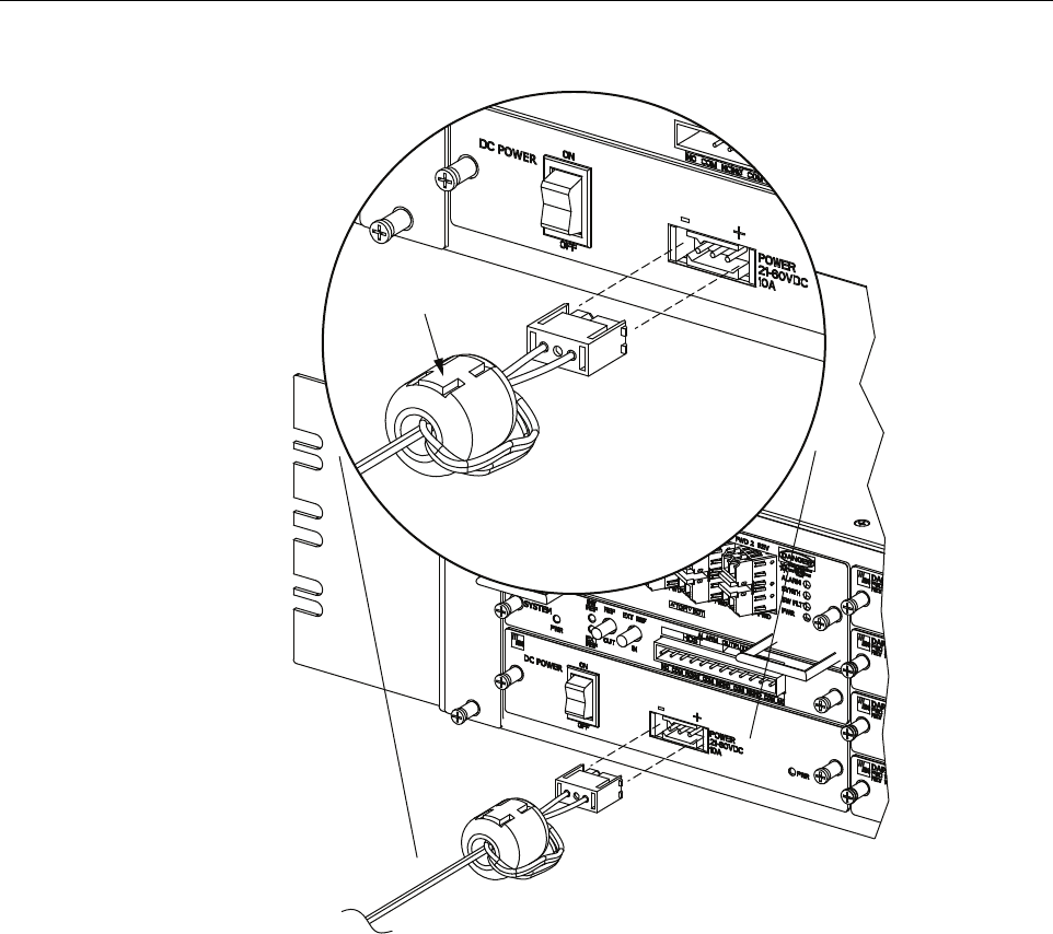
5. Route the wires to the terminal block (Figure 19) on the HU Power Supply and cut them to
length, allowing sufficient length for termination.
6. Loop both power wires around and through the Ferrite as shown in Figure 19.
7. Strip 1.27 cm (0.5 inch) of insulation from the end of each wire.
8. Insert one end of each wire into the terminal block, one into + and the other into the – position.
9. The terminal block must plug into the three-pin receptacle on the front of the HU Power
Supply.
10. Install fuses in the fuse panel. Update office records as required.
11.
Turn power switch on power supply ON.
12. The procedure for checking the voltage level and verifying that the HU is ready to power up
is provided in the applicable System Operation and Maintenance Manual (see Related
Publications section).
Note: All DC input wiring should be routed away from any sharp edges and properly
secured in place to prevent chafing and to provide strain relief. This may be achieved by
tie-wrapping wires to the rack frame or by a similar means.
Note: When connecting the equipment to the supply circuit, be sure to check equipment
nameplate ratings to avoid overloading circuits which may cause damage to over-current
protection devices and supply wiring.
ADCP-75-348 • Issue 1 • 04/2008
Page 27
© 2008, ADC Telecommunications, Inc.
Figure 19. DC Power Connections
6.14 Installation Complete
When the installation is complete, refer to the applicable System User Manual (see Related
Publications section) for the system turn-up and test procedures.
7 MAINTENANCE
This section provides the HU maintenance procedures. Refer to this section when scheduled
maintenance is required. The fault isolation and troubleshooting procedures are provided in the
applicable System Operation and Maintenance Manual (see Related Publications section). Host
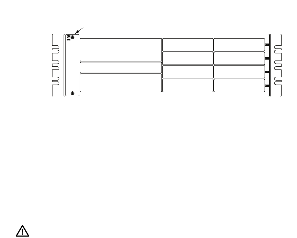
Unit card locations are shown in Figure 20.
22405-A
FERRITE
ADCP-75-348 • Issue 1 • 04/2008
Page 28
© 2008, ADC Telecommunications, Inc.
Figure 20. Host Unit Card Locations
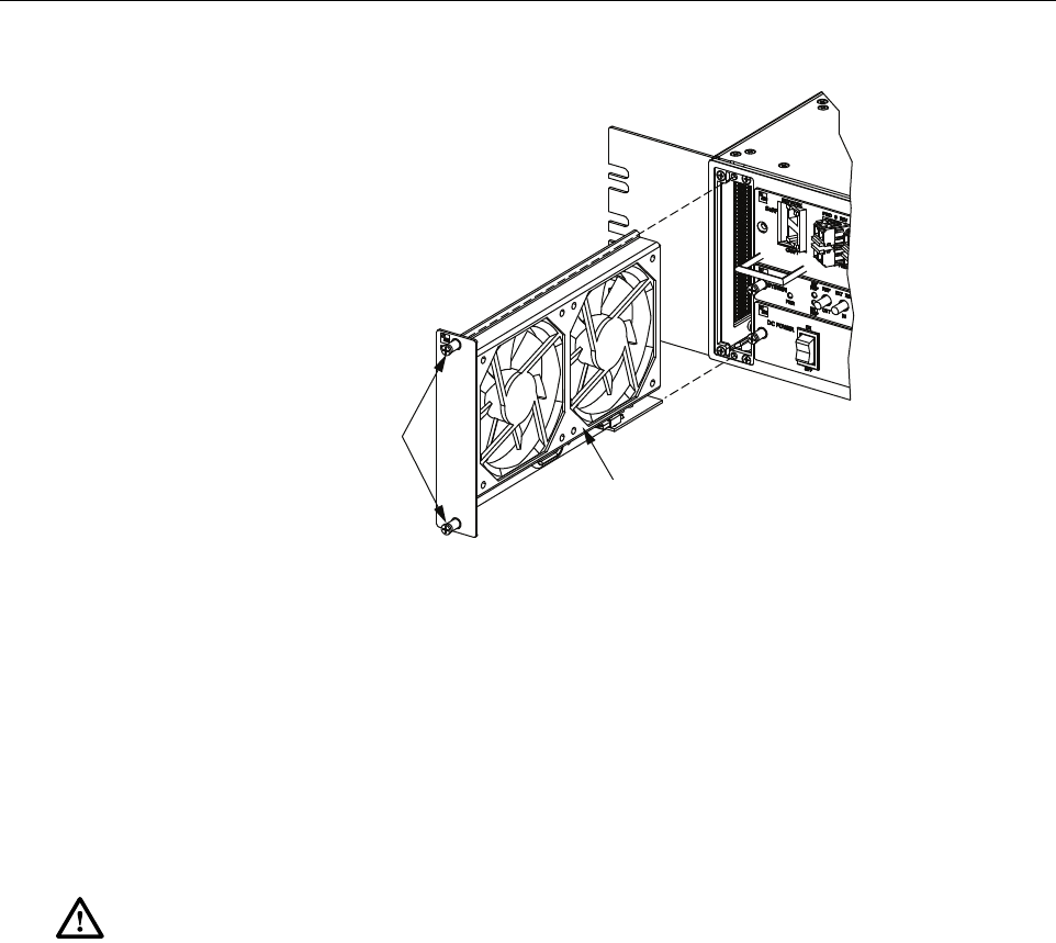
7.1 Host Unit Fan Replacement Procedure
The HU is equipped with a fan assembly consisting of two cooling fans which is located on the
left side of the HU enclosure. The cooling fans blow cool air into the enclosure. Heated air is
exhausted through the vent openings on the right side of the enclosure. Replacement of fan
assembly does not require that the HU be turned off. The recommended replacement interval is
60 months. Use the following procedure to remove and replace the HU cooling fans:
1. Before working on the HU or handling a fan, slip on an Electro-Static Discharge (ESD)
wrist strap and connect the ground wire to an earth ground source. Wear the ESD wrist
strap while completing each section of the fan installation procedure.
2. Notify the NOC or alarm monitoring system operator that the fan is being replaced.
3. Loosen the two thumb screws that secure the fan/grill assembly to the front of the HU
enclosure as shown in Figure 21.
4. Carefully withdraw the fan/grill assembly from the enclosure.
5. Slide the new fan assembly into the HU chassis until it is firmly seated.
6. Secure the fan/grill assembly to the front of the enclosure (see Figure 21) using the two
screws loosened in Step 3.
7. Verify that the fans run properly following power-up.
8. Notify the NOC or alarm monitoring system operator that the fans are back in operation.
Warning: Electronic components can be damaged by static electrical discharge. To prevent
ESD damage, always wear an ESD wrist strap when working on the HU and when handling
electronic components.
SeRF CARD
SYSTEM CARD
POWER SUPPLY
DART CARD
DART CARD
DART CARD
DART CARD
DART CARD
DART CARD
DART CARD
DART CARD
FAN ASSEMBLY
22402-A
ADCP-75-348 • Issue 1 • 04/2008
Page 29
© 2008, ADC Telecommunications, Inc.
Figure 21. Host Unit Fan Assembly Removal
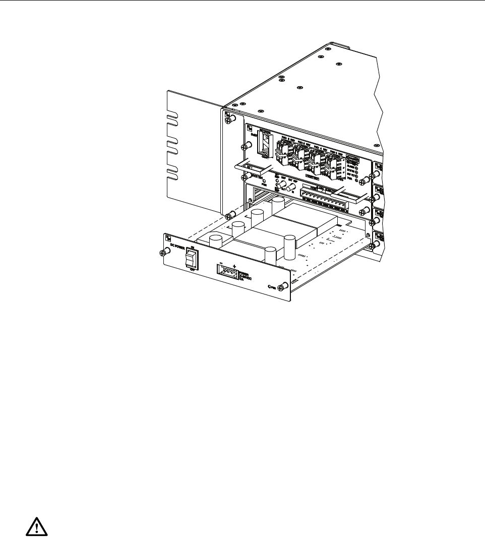
7.2 Power Supply Replacement Procedure
Removing the power supply will disable the Host Unit and interrupt service. Notify the NOC or
alarm monitoring system operator that the system will be out of service for a period of time.
1. Before working on the HU or handling a power supply, slip on an Electro-Static Discharge
(ESD) wrist strap and connect the ground wire to an earth ground source. Wear the ESD
wrist strap while completing each section of the fan installation procedure.
2. Turn power switch to the OFF position.
3. Unplug power plug by applying pressure to the left and right side of the connector and
pulling it straight out.
4. Loosen the two thumb screws that secure the Power Supply to the front of the HU
enclosure. See Figure 22.
5. Carefully withdraw the Power Supply from the enclosure.
6. Slide replacement Power Supply into the HU chassis until it is firmly seated.
7. Secure the Power Supply to the front of the enclosure using the two thumb screws
loosened in Step 4.
8. Plug power plug into the power connector on the front of the Power Supply. Make certain
that it is fully seated.
Warning: Electronic components can be damaged by static electrical discharge. To prevent
ESD damage, always wear an ESD wrist strap when working on the HU and when handling
electronic components.
22396-A
FAN
ASSEMBLY
THUMB
SCREWS
ADCP-75-348 • Issue 1 • 04/2008
Page 30
© 2008, ADC Telecommunications, Inc.
Figure 22. Power Supply Replacement
9. Turn power switch to the ON position.
10. Notify the NOC or alarm monitoring system operator that the system is back in operation.
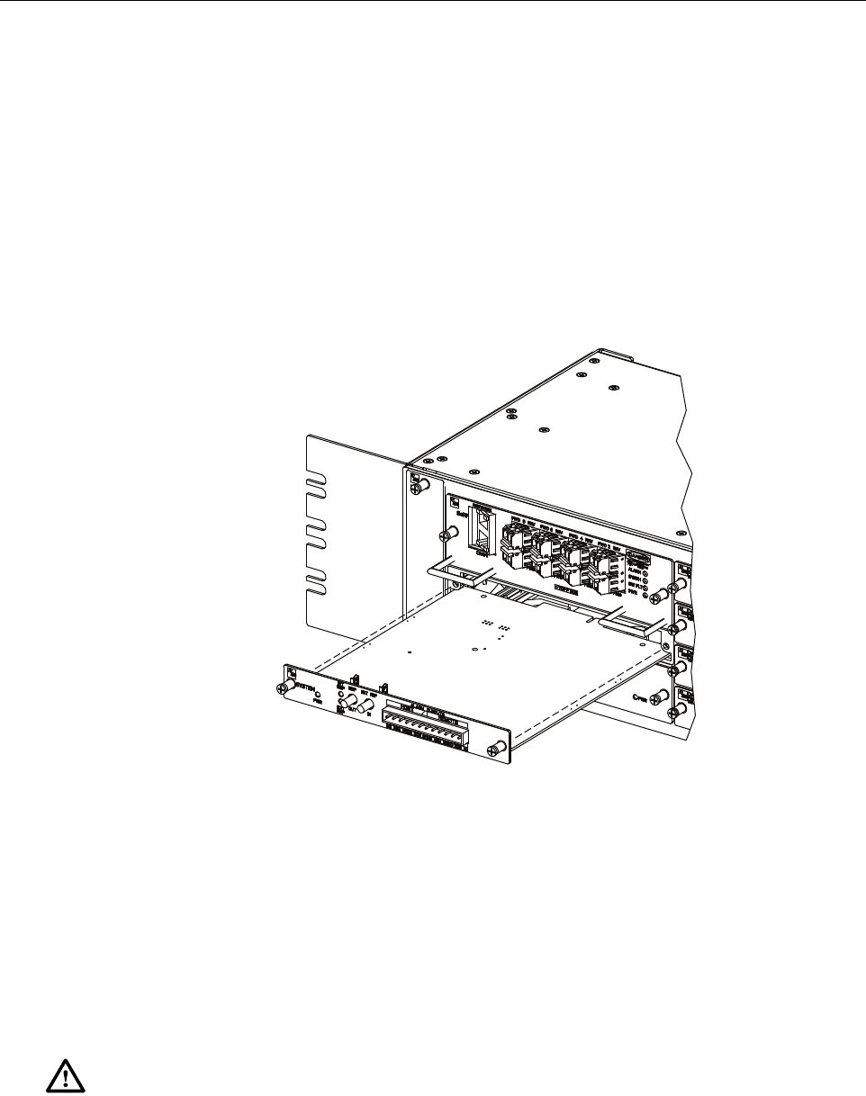
7.3 System Card Replacement Procedure
System Card can be replaced without disrupting service. If the EXT REF is being used
communications to other HU’s will be disrupted.
1. Before working on the HU or handling a System Card, slip on an Electro-Static Discharge
(ESD) wrist strap and connect the ground wire to an earth ground source. Wear the ESD
wrist strap while completing each section of the fan installation procedure.
2. Notify the NOC or alarm monitoring system operator that the System Card is being
replaced.
3. If used, disconnect EXT REF cables from the front of the System Card.
4. Remove alarm plug from the front of the System Card by pressing on the lock tabs.
5. Loosen the two thumb screws that secure the System Card to the front of the HU
enclosure. See Figure 23.
Warning: Electronic components can be damaged by static electrical discharge. To prevent
ESD damage, always wear an ESD wrist strap when working on the HU and when handling
electronic components.
22400-A
ADCP-75-348 • Issue 1 • 04/2008
Page 31
© 2008, ADC Telecommunications, Inc.
6. Carefully withdraw the System Card from the enclosure.
7. Slide replacement System Card into the HU chassis until it is firmly seated.
8. Secure the System Card to the front of the enclosure using the two thumb screws loosened
in Step 5.
9. If used, connect EXT REF cables to the front of the System Card.
10. Plug alarm plug into the connector on the System Card.
11. On the Power Supply turn the power switch OFF and then back ON to reset the System Card.
12. Notify the NOC or alarm monitoring system operator that the system is back in operation.
Figure 23. System Card Replacement
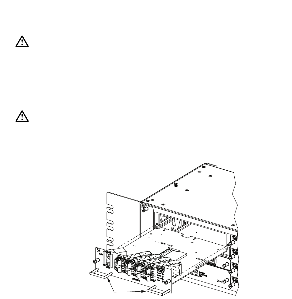
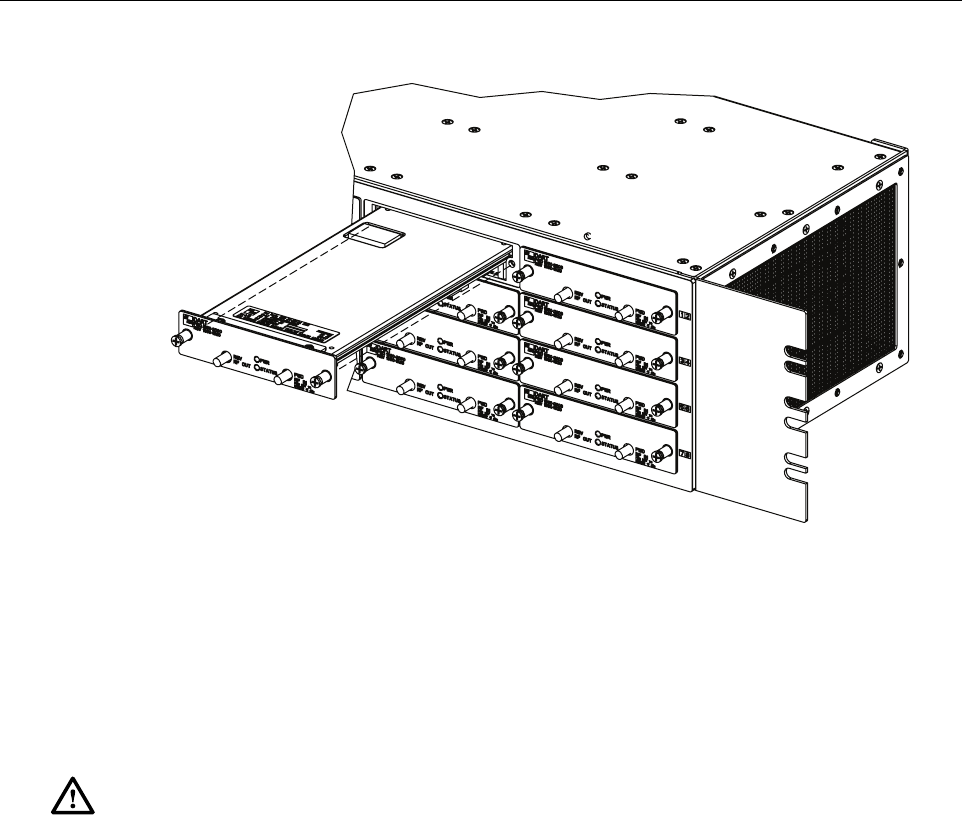
7.4 SeRF Card Replacement Procedure
Removing the SeRF Card will disable the Host Unit and interrupt service. Notify the NOC or
alarm monitoring system operator that the system will be out of service for a period of time.
1. Before working on the HU or handling a SeRF Card, slip on an Electro-Static Discharge
(ESD) wrist strap and connect the ground wire to an earth ground source. Wear the ESD
wrist strap while completing each section of the fan installation procedure.
Warning: Electronic components can be damaged by static electrical discharge. To prevent
ESD damage, always wear an ESD wrist strap when working on the HU and when handling
electronic components.
22398-A
ADCP-75-348 • Issue 1 • 04/2008
Page 32
© 2008, ADC Telecommunications, Inc.
2. Remove Network and Craft RJ-45 plugs from the front of the SeRF Card.
3. Remove fiber pigtails from the SFP’s. Note the location of the pigtails.
4. Loosen the two thumb screws that secure the System Card to the front of the HU
enclosure. See Figure 24.
Figure 24. SeRF Card Replacement
5. Use the two handles to carefully withdraw the SeRF Card from the enclosure.
6. Slide replacement SeRF Card into the HU chassis until it is firmly seated.
7. Secure the SeRF Card to the front of the enclosure using the two thumb screws loosened in
Step 4.
8. If necessary install new SFP’s or remove them from the SeRF card removed in Step 5 and
install them in the new SeRF Card.
9. Plug fiber pigtails back into the SFP’s.
Danger: This equipment uses a Class 1 Laser according to FDA/CDRH rules. Laser radiation
can seriously damage the retina of the eye. Do not look into the ends of any optical fiber. Do not
look directly into the optical transmitter of any unit or exposure to laser radiation may result.
An optical power meter should be used to verify active fibers. A protective cap or hood MUST
be immediately placed over any radiating transmitter or optical fiber connector to avoid the
potential of dangerous amounts of radiation exposure. This practice also prevents dirt particles
from entering the connector.
Caution:
Improper handling can damage fiber optic cables. Do not bend fiber optic cable more
sharply than the minimum recommended bend radius specified by the cable manufacturer. Do not
apply more pulling force to the cable than specified.
22397-A
HANDLES

ADCP-75-348 • Issue 1 • 04/2008
Page 33
© 2008, ADC Telecommunications, Inc.
10. Plug Network and Craft RJ-45 plugs into the connector on the SeRF Card. Make certain
the pigtails are inserted in the correct SFP.
11. Notify the NOC or alarm monitoring system operator that the system is back in operation.
7.5 DART Card Replacement/Installation Procedure
Each DART Card provides an interface between the SeRF and the Power Amplifier they are
spectrum specific. When additional service is needed another DART Card can be added to the
HU and the corresponding cover added to a Remote Unit. Individual DART Cards may be
replaced without disrupting service to the entire remote system. Only the RF spectrum of the
DART Card being removed is affected. Refer to Figure 25.
7.5.1 Replacement
1. Before working on the HU or handling a DART Card, slip on an Electro-Static Discharge
(ESD) wrist strap and connect the ground wire to an earth ground source. Wear the ESD
wrist strap while completing each section of the fan installation procedure.
2. Notify the NOC or alarm monitoring system operator that the DART Card is being
replaced.
3. Disconnect REF IN and OUT cables from the front of the DART Card.
4. Loosen the two thumb screws that secure the DART Card to the front of the HU enclosure.
5. Carefully withdraw the DART Card from the enclosure.
6. Slide replacement DART Card into the HU chassis until it is firmly seated.
7. Secure the DART Card to the front of the enclosure using the two thumb screws loosened
in Step 4.
8. Connect REF IN and OUT cables to the front of the DART Card.
9. Notify the NOC or alarm monitoring system operator that the system is back in operation.
Warning: Electronic components can be damaged by static electrical discharge. To prevent
ESD damage, always wear an ESD wrist strap when working on the HU and when handling
electronic components.
ADCP-75-348 • Issue 1 • 04/2008
Page 34
© 2008, ADC Telecommunications, Inc.
Figure 25. DART Card Replacement/Installation
7.5.2 Install New DART Card
1. Before working on the HU or handling a DART Card, slip on an Electro-Static Discharge
(ESD) wrist strap and connect the ground wire to an earth ground source. Wear the ESD
wrist strap while completing each section of the fan installation procedure.
2. Notify the NOC or alarm monitoring system operator that another DART Card is being
added the HU.
3. Determine slot location of the new DART Card. Remove blank panel from the front of the
HU.
4. Slide DART Card into the HU chassis until it is firmly seated.
5. Secure the DART Card to the front of the enclosure using the two thumb screws.
6. Obtain the required lengths of high performance, flexible, low loss 50-ohm coaxial
communications cable (RG-400 or equivalent) for all coaxial connections.
7. Route the forward and reverse path coaxial cables between the HU and the BTS interface
(per system design plan) and cut to the required length. Allow sufficient slack for dressing
and organizing cables at the HU and for installing an external attenuator in the forward
path link.
8. Terminate each cable with an QMA-type male connector following the connector
supplier’s recommendations.
9. If required, install an external attenuator in the forward path.
Warning: Electronic components can be damaged by static electrical discharge. To prevent
ESD damage, always wear an ESD wrist strap when working on the HU and when handling
electronic components.
22401-A

ADCP-75-348 • Issue 1 • 04/2008
Page 35
© 2008, ADC Telecommunications, Inc.
10. Connect the forward path cable to the FWD RF IN connector on the HU DART front
panel as shown in Figure 12.
11. Connect the reverse path cable to the REV RF OUT connector on the HU DART front
panel (see Figure 12).
12. Dress and secure cables at the right side of the HU.
13. Complete all remaining coaxial connections as specified in the system design plan.
14. Notify the NOC or alarm monitoring system operator that the DART Card is in operation.
Note: The composite forward path RF signal level at the HU must be between –25 and
+5 dBm. Do not connect the forward path cable until the composite forward path RF
signal level is measured and the amount of external attenuation required is determined.
ADCP-75-348 • Issue 1 • 04/2008
Page 36
© 2008, ADC Telecommunications, Inc.
8 CUSTOMER INFORMATION AND ASSISTANCE
13944-Q
Contents herein are current as of the date of publication. ADC reserves the right to change the contents
without prior notice. In no event shall ADC be liable for any damages resulting from loss of data,
loss of use, or loss of profits and ADC further disclaims any and all liability for indirect, incidental,
special, consequential or other similar damages. This disclaimer of liability applies to all products,
publications and services during and after the warranty period.
REPRINTS:
www.adc.com/manuals
PDF copies of manuals are available
for downloading at the following link:
PRODUCT INFORMATION AND TECHNICAL ASSISTANCE:
connectivity.tac@adc.com
wireless.tac@adc.com
euro.tac@adc.com
asiapacific.tac@adc.com
ADCP Number:
WRITE:
ADC Telecommunications (S’PORE) PTE, LTD;
100 Beach Road, #18-01, Shaw Towers.
Singapore 189702.
ADC Telecommunications, INC
PO Box 1101,
Minneapolis, MN 55440-1101, USA
ADC European Customer Service, INC
Belgicastraat 2,
1930 Zaventem, Belguim
PHONE:
U.S.A. or CANADA
Sales: 1-800-366-3891
Extension 73000
Technical Assistance: 1-800-366-3891
Connectivity Extension: 73475
Wireless Extension: 73476
EUROPE
Sales Administration: +32-2-712-65 00
Technical Assistance: +32-2-712-65 42
EUROPEAN TOLL FREE NUMBERS
Germany: 0180 2232923
UK: 0800 960236
Spain: 900 983291
France: 0800 914032
Italy: 0800 782374
ASIA/PACIFIC
Sales Administration: +65-6294-9948
Technical Assistance: +65-6393-0739
ELSEWHERE
Sales Administration: +1-952-917-3000
Technical Assistance: +1-952-917-3475
75-348