ADC Telecommunications U0559-011 InterReach Unison 700 MHz LTE Main HUB, Expansion HUB and Remote Access Unit User Manual unison
ADC Telecommunications Inc. InterReach Unison 700 MHz LTE Main HUB, Expansion HUB and Remote Access Unit unison
Users Manual
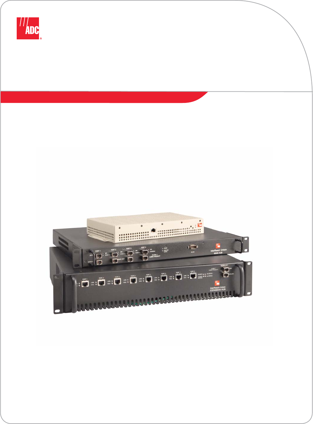
InterReach Unison®
Installation, Operation,
and Reference Manual
ADCP-77-053 • Issue 2 • 9/2009
D-620003-0-20 Rev M

ADCP-77-053 • Issue 2 • 9/2009 • Preface
Page ii
COPYRIGHT
© 2009, ADC Telecommunications, Inc.
All Rights Reserved
REVISION HISTORY
LIST OF CHANGES
The technical changes incorporated into this issue are listed below.
TRADEMARK INFORMATION
ADC is a registered trademark and InterReach, InterReach Unison, InterReach Fusion, WAVEXchange, FlexWave are registered
trademarks and trademarks of ADC Telecommunications, Inc. All other products, company names, service marks, and trademarks
mentioned in this document or website are used for identification purposes only and may be owned by other companies.
DISCLAIMER OF LIABILITY
Contents herein are current as of the date of publication. ADC reserves the right to change the contents without prior notice. In no
event shall ADC be liable for any damages resulting from loss of data, loss of use, or loss of profits and ADC further
disclaims any and all liability for indirect, incidental, special, consequential or other similar damages. This disclaimer of
liability applies to all products, publications and services during and after the warranty period.
This publication may be verified at any time by contacting ADC’s Technical Assistance Center at 1-800-366-3891, extension 73476
(in U.S.A. or Canada) or 952-917-3476 (outside U.S.A. and Canada), or by e-mail to wireless.tac@adc.com.
ISSUE DATE REASON FOR CHANGE
1 7/2008 First ADC release
2 9/2009 Add Unison 700 LTE product content
PAGE IDENTIFIER DESCRIPTION OF CHANGE
- Add Unison 700 LTE product content
ADC Telecommunications, Inc.
P.O. Box 1101, Minneapolis, Minnesota 55440-1101
In U.S.A. and Canada: 1-800-366-3891
Outside U.S.A. and Canada: (952) 938-8080
Fax: (952) 917-1717
ADC Telecommunications, Inc.
541 E. Trimble Road, San Jose, California 95131-1224 USA
In U.S.A. and Canada: 1-800-530-9960
Outside U.S.A. and Canada: 1-408-952-2400
Fax: 1-408-952-2410

InterReach Unison Installation, Operation, and Reference Manual i
D-620003-0-20 Rev M CONFIDENTIAL
Table of Contents
SECTION 1 General Information . . . . . . . . . . . . . . . . . . . . . . 1-1
1.1 Firmware Release . . . . . . . . . . . . . . . . . . . . . . . . . . . . . . . . . . 1-2
1.2 Purpose and Scope . . . . . . . . . . . . . . . . . . . . . . . . . . . . . . . . . 1-2
1.3 Conventions in this Manual . . . . . . . . . . . . . . . . . . . . . . . . . . 1-3
1.4 Acronyms in this Manual . . . . . . . . . . . . . . . . . . . . . . . . . . . . 1-4
1.5 Standards Conformance . . . . . . . . . . . . . . . . . . . . . . . . . . . . . 1-6
1.6 Related Publications . . . . . . . . . . . . . . . . . . . . . . . . . . . . . . . . 1-6
SECTION 2 InterReach Unison System Description . . . . . . 2-1
2.1 System Hardware . . . . . . . . . . . . . . . . . . . . . . . . . . . . . . . . . . 2-3
2.2 System OA&M Capabilities . . . . . . . . . . . . . . . . . . . . . . . . . . 2-4
2.2.1 OA&M Software . . . . . . . . . . . . . . . . . . . . . . . . . . . . . . . . . . . 2-7
2.2.2 Using Alarm Contacts . . . . . . . . . . . . . . . . . . . . . . . . . . . . . . . 2-9
2.3 System Connectivity . . . . . . . . . . . . . . . . . . . . . . . . . . . . . . . 2-11
2.4 System Operation . . . . . . . . . . . . . . . . . . . . . . . . . . . . . . . . . 2-12
2.5 System Specifications . . . . . . . . . . . . . . . . . . . . . . . . . . . . . . 2-13
2.5.1 InterReach Unison Wavelength and Laser Power . . . . . . . . . 2-14
2.5.2 Environmental Specifications . . . . . . . . . . . . . . . . . . . . . . . . 2-14
2.5.3 Operating Frequencies . . . . . . . . . . . . . . . . . . . . . . . . . . . . . . 2-15
2.5.4 RF End-to-End Performance . . . . . . . . . . . . . . . . . . . . . . . . . 2-16
SECTION 3 Unison Main Hub . . . . . . . . . . . . . . . . . . . . . . . . 3-1
3.1 Main Hub Front Panel . . . . . . . . . . . . . . . . . . . . . . . . . . . . . . 3-2
3.1.1 Optical Fiber Uplink/Downlink Ports . . . . . . . . . . . . . . . . . . . 3-3
3.1.2 Communications RS-232 Serial Connector . . . . . . . . . . . . . . 3-3
3.1.3 LED Indicators . . . . . . . . . . . . . . . . . . . . . . . . . . . . . . . . . . . . 3-4
3.2 Main Hub Rear Panel . . . . . . . . . . . . . . . . . . . . . . . . . . . . . . . 3-7
3.2.1 Main Hub Rear Panel Connectors . . . . . . . . . . . . . . . . . . . . . . 3-8
3.3 Main Hub Specifications . . . . . . . . . . . . . . . . . . . . . . . . . . . . 3-9
3.4 Faults, Warnings, and Status Messages . . . . . . . . . . . . . . . . 3-10
3.4.1 Description . . . . . . . . . . . . . . . . . . . . . . . . . . . . . . . . . . . . . . 3-10

ii InterReach Unison Installation, Operation, and Reference Manual
CONFIDENTIAL D-620003-0-20 Rev M
3.4.2 View Preference . . . . . . . . . . . . . . . . . . . . . . . . . . . . . . . . . . . 3-10
SECTION 4 Unison Expansion Hub . . . . . . . . . . . . . . . . . . . . 4-1
4.1 Expansion Hub Front Panel . . . . . . . . . . . . . . . . . . . . . . . . . . 4-2
4.1.1 RJ-45 Connectors . . . . . . . . . . . . . . . . . . . . . . . . . . . . . . . . . . . 4-3
4.1.2 Optical Fiber Uplink/Downlink Connectors . . . . . . . . . . . . . . 4-3
4.1.3 LED Indicators . . . . . . . . . . . . . . . . . . . . . . . . . . . . . . . . . . . . . 4-3
4.2 Expansion Hub Rear Panel . . . . . . . . . . . . . . . . . . . . . . . . . . . 4-6
4.3 Faults, Warnings, and Status Messages . . . . . . . . . . . . . . . . . . 4-7
4.4 Expansion Hub Specifications . . . . . . . . . . . . . . . . . . . . . . . . 4-8
SECTION 5 Unison Remote Access Unit . . . . . . . . . . . . . . . 5-1
5.1 Remote Access Unit Connectors . . . . . . . . . . . . . . . . . . . . . . . 5-4
5.1.1 SMA Connector . . . . . . . . . . . . . . . . . . . . . . . . . . . . . . . . . . . . 5-4
5.1.2 RJ-45 Connector . . . . . . . . . . . . . . . . . . . . . . . . . . . . . . . . . . . 5-4
5.2 LED Indicators . . . . . . . . . . . . . . . . . . . . . . . . . . . . . . . . . . . . 5-4
5.3 Faults, Warnings, and Status Messages . . . . . . . . . . . . . . . . . . 5-6
5.4 Remote Access Unit Specifications . . . . . . . . . . . . . . . . . . . . 5-6
5.5 RAUs in a Dual Band System . . . . . . . . . . . . . . . . . . . . . . . . . 5-7
SECTION 6 Designing a Unison Solution . . . . . . . . . . . . . . . 6-1
6.1 Maximum Output Power Per Carrier at RAU . . . . . . . . . . . . . 6-3
6.1.1 700 MHz LTE . . . . . . . . . . . . . . . . . . . . . . . . . . . . . . . . . . . . . 6-4
6.1.2 800 MHz Cellular . . . . . . . . . . . . . . . . . . . . . . . . . . . . . . . . . . 6-5
6.1.3 800 MHz iDEN/SMR . . . . . . . . . . . . . . . . . . . . . . . . . . . . . . . 6-6
6.1.4 900 MHz GSM and EDGE . . . . . . . . . . . . . . . . . . . . . . . . . . . 6-7
6.1.5 1800 MHz DCS . . . . . . . . . . . . . . . . . . . . . . . . . . . . . . . . . . . . 6-8
6.1.6 1900 MHz PCS . . . . . . . . . . . . . . . . . . . . . . . . . . . . . . . . . . . . 6-9
6.1.7 2.1 GHz UMTS . . . . . . . . . . . . . . . . . . . . . . . . . . . . . . . . . . . 6-10
6.1.8 1.7/2.1 GHz AWS . . . . . . . . . . . . . . . . . . . . . . . . . . . . . . . . . 6-10
6.1.9 700 MHz Public Safety . . . . . . . . . . . . . . . . . . . . . . . . . . . . . 6-11
6.2 Estimating RF Coverage . . . . . . . . . . . . . . . . . . . . . . . . . . . . 6-13
6.2.1 Path Loss Equation . . . . . . . . . . . . . . . . . . . . . . . . . . . . . . . . 6-14
6.2.2 Coverage Distance . . . . . . . . . . . . . . . . . . . . . . . . . . . . . . . . . 6-15
6.2.3 Examples of Design Estimates . . . . . . . . . . . . . . . . . . . . . . . 6-21
6.3 System Gain . . . . . . . . . . . . . . . . . . . . . . . . . . . . . . . . . . . . . 6-25
6.3.1 System Gain (Loss) Relative to ScTP Cable Length . . . . . . . 6-25
6.4 Link Budget Analysis . . . . . . . . . . . . . . . . . . . . . . . . . . . . . . 6-26
6.4.1 Elements of a Link Budget for Narrowband Standards . . . . . 6-26
6.4.2 Narrowband Link Budget Analysis
for a Microcell Application . . . . . . . . . . . . . . . . . . . . . . . . . . 6-29
6.4.3 Elements of a Link Budget for CDMA Standards . . . . . . . . . 6-31
6.4.4 CDMA Link Budget Analysis for a Microcell Application . 6-34
6.4.5 Considerations for Re-Radiation (Over-the-Air) Systems . . . 6-37
6.5 Optical Power Budget . . . . . . . . . . . . . . . . . . . . . . . . . . . . . . 6-38

InterReach Unison Installation, Operation, and Reference Manual iii
D-620003-0-20 Rev M CONFIDENTIAL
6.6 Connecting a Main Hub to a Base Station . . . . . . . . . . . . . . 6-39
6.6.1 Attenuation . . . . . . . . . . . . . . . . . . . . . . . . . . . . . . . . . . . . . . 6-40
6.6.2 Uplink Attenuation . . . . . . . . . . . . . . . . . . . . . . . . . . . . . . . . 6-41
6.6.3 RAU Attenuation and ALC . . . . . . . . . . . . . . . . . . . . . . . . . . 6-43
6.7 Designing for a Neutral Host System . . . . . . . . . . . . . . . . . . 6-46
SECTION 7 Installing Unison . . . . . . . . . . . . . . . . . . . . . . . . . 7-1
7.1 Installation Requirements . . . . . . . . . . . . . . . . . . . . . . . . . . . . 7-1
7.1.1 Component Location Requirements . . . . . . . . . . . . . . . . . . . . 7-2
7.1.2 Cable and Connector Requirements . . . . . . . . . . . . . . . . . . . . 7-2
7.1.3 Multiple Operator System Recommendations . . . . . . . . . . . . 7-2
7.1.4 Distance Requirements . . . . . . . . . . . . . . . . . . . . . . . . . . . . . . 7-2
7.2 Safety Precautions . . . . . . . . . . . . . . . . . . . . . . . . . . . . . . . . . 7-4
7.2.1 Installation Guidelines . . . . . . . . . . . . . . . . . . . . . . . . . . . . . . . 7-4
7.2.2 General Safety Precautions . . . . . . . . . . . . . . . . . . . . . . . . . . . 7-4
7.2.3 Fiber Port Safety Precautions . . . . . . . . . . . . . . . . . . . . . . . . . 7-5
7.3 Preparing for System Installation . . . . . . . . . . . . . . . . . . . . . . 7-6
7.3.1 Pre-Installation Inspection . . . . . . . . . . . . . . . . . . . . . . . . . . . . 7-6
7.3.2 Installation Checklist . . . . . . . . . . . . . . . . . . . . . . . . . . . . . . . . 7-6
7.3.3 Tools and Materials Required . . . . . . . . . . . . . . . . . . . . . . . . . 7-9
7.3.4 Optional Accessories . . . . . . . . . . . . . . . . . . . . . . . . . . . . . . . . 7-9
7.4 Unison Component Installation Procedures . . . . . . . . . . . . . 7-11
7.4.1 Installing a Main Hub . . . . . . . . . . . . . . . . . . . . . . . . . . . . . . 7-13
7.4.2 Installing Expansion Hubs . . . . . . . . . . . . . . . . . . . . . . . . . . . 7-18
7.4.3 Installing RAUs . . . . . . . . . . . . . . . . . . . . . . . . . . . . . . . . . . . 7-23
7.4.4 Installing a Dual-Band RAU Configuration . . . . . . . . . . . . . 7-27
7.4.5 Using a Cat-5 Extender . . . . . . . . . . . . . . . . . . . . . . . . . . . . . 7-29
7.4.6 Configuring the System . . . . . . . . . . . . . . . . . . . . . . . . . . . . . 7-30
7.5 Splicing Fiber Optic Cable . . . . . . . . . . . . . . . . . . . . . . . . . . 7-33
7.5.1 Fusion Splices . . . . . . . . . . . . . . . . . . . . . . . . . . . . . . . . . . . . 7-33
7.6 Interfacing a Main Hub to a Base Station
or a Roof-top Antenna . . . . . . . . . . . . . . . . . . . . . . . . . . . . . 7-35
7.6.1 Connecting Multiple Main Hubs . . . . . . . . . . . . . . . . . . . . . . 7-38
7.7 Connecting Contact Alarms to a Unison System . . . . . . . . . 7-42
7.7.1 Alarm Source . . . . . . . . . . . . . . . . . . . . . . . . . . . . . . . . . . . . . 7-43
7.7.2 Alarm Sense . . . . . . . . . . . . . . . . . . . . . . . . . . . . . . . . . . . . . 7-46
7.7.3 Alarm Cables . . . . . . . . . . . . . . . . . . . . . . . . . . . . . . . . . . . . . 7-49
7.8 Alarm Monitoring Connectivity Options . . . . . . . . . . . . . . . 7-51
7.8.1 Direct Connection . . . . . . . . . . . . . . . . . . . . . . . . . . . . . . . . . 7-51
7.8.2 Modem Connection . . . . . . . . . . . . . . . . . . . . . . . . . . . . . . . . 7-52
7.8.3 RS-232 Port Expander Connection . . . . . . . . . . . . . . . . . . . . 7-53
7.8.4 POTS Line Sharing Switch Connection . . . . . . . . . . . . . . . . 7-54
7.8.5 Ethernet and ENET/RS-232 Serial Hub Connection . . . . . . 7-55
7.8.6 Network Interface Unit (NIU) . . . . . . . . . . . . . . . . . . . . . . . . 7-56

iv InterReach Unison Installation, Operation, and Reference Manual
CONFIDENTIAL D-620003-0-20 Rev M
SECTION 8 Replacing Unison Components . . . . . . . . . . . . . 8-1
8.1 Replacing an RAU . . . . . . . . . . . . . . . . . . . . . . . . . . . . . . . . . 8-1
8.2 Replacing an Expansion Hub . . . . . . . . . . . . . . . . . . . . . . . . . 8-3
8.3 Replacing a Main Hub . . . . . . . . . . . . . . . . . . . . . . . . . . . . . . 8-4
SECTION 9 Maintenance, Troubleshooting,
and Technical Assistance . . . . . . . . . . . . . . . . . 9-1
9.1 Service . . . . . . . . . . . . . . . . . . . . . . . . . . . . . . . . . . . . . . . . . . . 9-1
9.2 Maintenance . . . . . . . . . . . . . . . . . . . . . . . . . . . . . . . . . . . . . . 9-2
9.3 Troubleshooting . . . . . . . . . . . . . . . . . . . . . . . . . . . . . . . . . . . 9-3
9.3.1 Troubleshooting using AdminManager . . . . . . . . . . . . . . . . . . 9-4
9.3.2 Troubleshooting using LEDs . . . . . . . . . . . . . . . . . . . . . . . . . 9-27
9.4 Troubleshooting CAT-5/5E/6 . . . . . . . . . . . . . . . . . . . . . . . . 9-31
9.5 Technical Assistance . . . . . . . . . . . . . . . . . . . . . . . . . . . . . . . 9-33
APPENDIX A Cables and Connectors . . . . . . . . . . . . . . . . . . . A-1
A.1 CAT-5E/6 Cable (ScTP) . . . . . . . . . . . . . . . . . . . . . . . . . . . . .A-1
A.2 Fiber Optical Cables . . . . . . . . . . . . . . . . . . . . . . . . . . . . . . . .A-3
A.3 Coaxial Cable . . . . . . . . . . . . . . . . . . . . . . . . . . . . . . . . . . . . .A-3
A.4 Standard Modem Cable . . . . . . . . . . . . . . . . . . . . . . . . . . . . .A-3
A.5 DB-9 to DB-9 Null Modem Cable . . . . . . . . . . . . . . . . . . . . .A-4
A.6 DB-25 to DB-9 Null Modem Cable . . . . . . . . . . . . . . . . . . . .A-5
APPENDIX B Compliance . . . . . . . . . . . . . . . . . . . . . . . . . . . . . B-1
B.1 Unison System Approval Status . . . . . . . . . . . . . . . . . . . . . . . B-1
B.2 Human Exposure to RF . . . . . . . . . . . . . . . . . . . . . . . . . . . . .B-3
APPENDIX C Changes and New Capabilities . . . . . . . . . . . . . C-1
C.1 New in Rev. M of Manual . . . . . . . . . . . . . . . . . . . . . . . . . . . C-1
C.2 New in Rev. L of Manual . . . . . . . . . . . . . . . . . . . . . . . . . . . . C-1
C.3 New in Rev. K of Manual . . . . . . . . . . . . . . . . . . . . . . . . . . . . C-1
C.4 New in Rev. J of Manual . . . . . . . . . . . . . . . . . . . . . . . . . . . .C-1
C.5 New in Rev. H. of Manual . . . . . . . . . . . . . . . . . . . . . . . . . . . C-2
C.6 New in Rev. G of Manual . . . . . . . . . . . . . . . . . . . . . . . . . . . . C-2
C.7 New in Rev. F of Manual . . . . . . . . . . . . . . . . . . . . . . . . . . . . C-2
C.8 New in Rev. E of Manual . . . . . . . . . . . . . . . . . . . . . . . . . . . . C-2
C.9 New in Rev. D of Manual . . . . . . . . . . . . . . . . . . . . . . . . . . . . C-3
C.10 New in Rev. C of Manual . . . . . . . . . . . . . . . . . . . . . . . . . . . C-3
C.11 New in Rev. B of Manual . . . . . . . . . . . . . . . . . . . . . . . . . . .C-3
APPENDIX D Glossary . . . . . . . . . . . . . . . . . . . . . . . . . . . . . . . . D-1

InterReach Unison Installation, Operation, and Reference Manual v
D-620003-0-20 Rev M CONFIDENTIAL
List of Figures
Figure 2-1 Unison System Hardware . . . . . . . . . . . . . . . . . . . . . . . . . . . . . . . . . . . . 2-3
Figure 2-2 OA&M Communications . . . . . . . . . . . . . . . . . . . . . . . . . . . . . . . . . . . . 2-4
Figure 2-3 Local System Monitoring and Reporting . . . . . . . . . . . . . . . . . . . . . . . 2-7
Figure 2-4 Remote System Monitoring and Reporting . . . . . . . . . . . . . . . . . . . . . . 2-8
Figure 2-5 Alarm Source . . . . . . . . . . . . . . . . . . . . . . . . . . . . . . . . . . . . . . . . . . . . . 2-9
Figure 2-6 Alarm Sense. . . . . . . . . . . . . . . . . . . . . . . . . . . . . . . . . . . . . . . . . . . . . 2-10
Figure 2-7 Unison’s Double Star Architecture . . . . . . . . . . . . . . . . . . . . . . . . . . . 2-11
Figure 2-8 Downlink (Base Station to Wireless Devices) . . . . . . . . . . . . . . . . . . . 2-12
Figure 2-9 Uplink (Wireless Devices to Base Station) . . . . . . . . . . . . . . . . . . . . . 2-12
Figure 3-1 Main Hub in a Unison System . . . . . . . . . . . . . . . . . . . . . . . . . . . . . . . . 3-1
Figure 3-2 Main Hub Block Diagram . . . . . . . . . . . . . . . . . . . . . . . . . . . . . . . . . . . 3-1
Figure 3-3 Main Hub Front Panel . . . . . . . . . . . . . . . . . . . . . . . . . . . . . . . . . . . . . . 3-2
Figure 3-4 Main Hub Rear Panel . . . . . . . . . . . . . . . . . . . . . . . . . . . . . . . . . . . . . . . 3-7
Figure 4-1 Expansion Hub in a Unison System . . . . . . . . . . . . . . . . . . . . . . . . . . . . 4-1
Figure 4-2 Expansion Hub Block Diagram . . . . . . . . . . . . . . . . . . . . . . . . . . . . . . . 4-1
Figure 4-3 Expansion Hub Front Panel . . . . . . . . . . . . . . . . . . . . . . . . . . . . . . . . . . 4-2
Figure 4-4 Expansion Hub Rear Panel . . . . . . . . . . . . . . . . . . . . . . . . . . . . . . . . . . . 4-6
Figure 5-1 Remote Access Unit in a Unison System . . . . . . . . . . . . . . . . . . . . . . . . 5-1
Figure 5-2 Remote Access Unit Block Diagram . . . . . . . . . . . . . . . . . . . . . . . . . . . 5-2
Figure 5-3 Dual-Port Antenna Configuration . . . . . . . . . . . . . . . . . . . . . . . . . . . . . 5-7
Figure 6-1 Determining Path Loss between the Antenna and the Wireless Device 6-13
Figure 6-2 Connecting Main Hubs to a Simplex Base Station . . . . . . . . . . . . . . . 6-39
Figure 6-3 Main Hub to Duplex Base Station or Repeater Connections . . . . . . . . 6-40
Figure 6-4 ALC Operation . . . . . . . . . . . . . . . . . . . . . . . . . . . . . . . . . . . . . . . . . . . 6-43
Figure 7-1 Mounting Bracket Detail . . . . . . . . . . . . . . . . . . . . . . . . . . . . . . . . . . . 7-13
Figure 7-2 Mounting Bracket Installation . . . . . . . . . . . . . . . . . . . . . . . . . . . . . . . 7-19
Figure 7-3 800 MHz Spectrum . . . . . . . . . . . . . . . . . . . . . . . . . . . . . . . . . . . . . . . 7-24
Figure 7-4 Guideline for Unison RAU Antenna Placement . . . . . . . . . . . . . . . . . 7-24

vi InterReach Unison Installation, Operation, and Reference Manual
CONFIDENTIAL D-620003-0-20 Rev M
Figure 7-5 Dual Band RAU Configuration . . . . . . . . . . . . . . . . . . . . . . . . . . . . . . 7-28
Figure 7-6 Dual-Port Antenna Configuration . . . . . . . . . . . . . . . . . . . . . . . . . . . . 7-29
Figure 7-7 Simplex Base Station to a Main Hub . . . . . . . . . . . . . . . . . . . . . . . . . . 7-35
Figure 7-8 Duplex Base Station to a Main Hub . . . . . . . . . . . . . . . . . . . . . . . . . . . 7-36
Figure 7-9 Connecting a Main Hub to Multiple Base Stations . . . . . . . . . . . . . . . 7-37
Figure 7-10 Connecting Two Main Hubs to a Simplex Repeater or Base Station . . 7-39
Figure 7-11 Connecting Two Main Hubs to a Duplex Repeater or Base Station . . 7-41
Figure 7-12 Connecting FlexWave to Unison . . . . . . . . . . . . . . . . . . . . . . . . . . . . . 7-43
Figure 7-13 Using a BTS to Monitor Unison . . . . . . . . . . . . . . . . . . . . . . . . . . . . . . 7-44
Figure 7-14 Using a BTS and OpsConsole to Monitor Unison . . . . . . . . . . . . . . . . 7-45
Figure 7-15 Connecting LGCell to Unison . . . . . . . . . . . . . . . . . . . . . . . . . . . . . . . 7-46
Figure 7-16 Alarm Sense Contacts . . . . . . . . . . . . . . . . . . . . . . . . . . . . . . . . . . . . . . 7-46
Figure 7-17 5-port Alarm Daisy-Chain Cable . . . . . . . . . . . . . . . . . . . . . . . . . . . . . 7-49
Figure 7-18 Alarm Sense Adapter Cable . . . . . . . . . . . . . . . . . . . . . . . . . . . . . . . . . 7-50
Figure 7-19 OA&M Direct Connection . . . . . . . . . . . . . . . . . . . . . . . . . . . . . . . . . . 7-51
Figure 7-20 OA&M Modem Connection . . . . . . . . . . . . . . . . . . . . . . . . . . . . . . . . . 7-52
Figure 7-21 OA&M Connection using an RS-232 Port Expander . . . . . . . . . . . . . . 7-53
Figure 7-22 OA&M Connection using a POTS Line Sharing Switch . . . . . . . . . . . 7-54
Figure 7-23 Cascading Line Sharing Switches . . . . . . . . . . . . . . . . . . . . . . . . . . . . 7-54
Figure 7-24 OA&M Connection using Ethernet and ENET/232 Serial Hub . . . . . . 7-55
Figure 7-25 Network Interface Unit (NIU) Configuration Options . . . . . . . . . . . . . 7-56
Figure 7-26 Multiple Unison Systems Monitored
by a Single Network Management System . . . . . . . . . . . . . . . . . . . . . . . . . . . . . . . . 7-57
Figure A-1 Wiring Map for Cat-5E/6 Cable . . . . . . . . . . . . . . . . . . . . . . . . . . . . . .A-2
Figure A-2 Standard Modem Cable Pinout . . . . . . . . . . . . . . . . . . . . . . . . . . . . . . .A-3
Figure A-3 DB-9 Female to DB-9 Female Null Modem Cable Diagram . . . . . . . .A-4
Figure A-4 DB-25 Male to DB-9 Female Null Modem Cable Diagram . . . . . . . . .A-5

InterReach Unison Installation, Operation, and Reference Manual vii
D-620003-0-20 Rev M CONFIDENTIAL
List of Tables
Table 1-1 Type Style Conventions . . . . . . . . . . . . . . . . . . . . . . . . . . . . . . . . . . . . . 1-3
Table 2-1 AdminManager and OpsConsole Functional Differences . . . . . . . . . . 2-5
Table 2-2 AdminManager and OpsConsole Connectivity Differences . . . . . . . . . 2-6
Table 2-3 System Specifications . . . . . . . . . . . . . . . . . . . . . . . . . . . . . . . . . . . . . 2-13
Table 2-4 InterReach Unison Wavelength and Laser Power . . . . . . . . . . . . . . . . 2-14
Table 2-5 Environmental Specifications . . . . . . . . . . . . . . . . . . . . . . . . . . . . . . . 2-14
Table 2-6 Operating Frequencies . . . . . . . . . . . . . . . . . . . . . . . . . . . . . . . . . . . . . 2-15
Table 2-7 Cellular RF End-to-End Performance . . . . . . . . . . . . . . . . . . . . . . . . . 2-16
Table 2-8 iDEN RF End-to-End Performance . . . . . . . . . . . . . . . . . . . . . . . . . . . 2-16
Table 2-9 GSM/EGSM RF End-to-End Performance . . . . . . . . . . . . . . . . . . . . . 2-17
Table 2-10 DCS RF End-to-End Performance . . . . . . . . . . . . . . . . . . . . . . . . . . . 2-17
Table 2-11 PCS RF End-to-End Performance . . . . . . . . . . . . . . . . . . . . . . . . . . . . 2-18
Table 2-12 UMTS RF End-to-End Performance** . . . . . . . . . . . . . . . . . . . . . . . . 2-18
Table 2-13 AWS RF End-to-End Performance . . . . . . . . . . . . . . . . . . . . . . . . . . . 2-19
Table 2-14 Public Safety 700 MHz RF End-to-End Performance . . . . . . . . . . . . 2-19
Table 2-15 700 MHz (Upper C) RF End-to-End Performance . . . . . . . . . . . . . . . 2-20
Table 3-1 Main Hub Status LED States . . . . . . . . . . . . . . . . . . . . . . . . . . . . . . . . . 3-5
Table 3-2 Main Hub Port LED States . . . . . . . . . . . . . . . . . . . . . . . . . . . . . . . . . . 3-6
Table 3-3 9-pin D-sub Connector Functions . . . . . . . . . . . . . . . . . . . . . . . . . . . . . 3-8
Table 3-4 Main Hub Specifications . . . . . . . . . . . . . . . . . . . . . . . . . . . . . . . . . . . . 3-9
Table 4-1 Expansion Hub Unit Status and DL/UL Status LED States . . . . . . . . . 4-4
Table 4-2 Expansion Hub Port LED States . . . . . . . . . . . . . . . . . . . . . . . . . . . . . . 4-5
Table 4-3 DB-9 Pin Connectors . . . . . . . . . . . . . . . . . . . . . . . . . . . . . . . . . . . . . . 4-6
Table 4-4 Expansion Hub Specifications . . . . . . . . . . . . . . . . . . . . . . . . . . . . . . . 4-8
Table 5-1 Frequency Bands covered by Unison RAUs . . . . . . . . . . . . . . . . . . . . . 5-3
Table 5-2 Remote Access Unit LED States . . . . . . . . . . . . . . . . . . . . . . . . . . . . . . 5-5
Table 5-3 Remote Access Unit Specifications . . . . . . . . . . . . . . . . . . . . . . . . . . . 5-6
Table 6-1 700 MHz Power per Carrier . . . . . . . . . . . . . . . . . . . . . . . . . . . . . . . . . 6-4

viii InterReach Unison Installation, Operation, and Reference Manual
CONFIDENTIAL D-620003-0-20 Rev M
Table 6-2 Cellular Power per Carrier . . . . . . . . . . . . . . . . . . . . . . . . . . . . . . . . . . . 6-5
Table 6-3 iDEN/SMR Power per Carrier . . . . . . . . . . . . . . . . . . . . . . . . . . . . . . . . 6-6
Table 6-4 GSM and EDGE Power per Carrier . . . . . . . . . . . . . . . . . . . . . . . . . . . 6-7
Table 6-5 DCS Power per Carrier . . . . . . . . . . . . . . . . . . . . . . . . . . . . . . . . . . . . . 6-8
Table 6-6 PCS Power per Carrier . . . . . . . . . . . . . . . . . . . . . . . . . . . . . . . . . . . . . 6-9
Table 6-7 UMTS Power per Carrier** . . . . . . . . . . . . . . . . . . . . . . . . . . . . . . . . 6-10
Table 6-8 AWS Power per Carrier . . . . . . . . . . . . . . . . . . . . . . . . . . . . . . . . . . . . 6-10
Table 6-9 Public Safety 700 MHz Power per Carrier . . . . . . . . . . . . . . . . . . . . . 6-11
Table 6-10 900 MHz Paging/SMR/iDEN . . . . . . . . . . . . . . . . . . . . . . . . . . . . . . . 6-11
Table 6-11 800 MHz Cellular/1900 MHz PCS Power per Carrier . . . . . . . . . . . . 6-12
Table 6-12 Coaxial Cable Losses (Lcoax) . . . . . . . . . . . . . . . . . . . . . . . . . . . . . . . 6-13
Table 6-13 Average Signal Loss of Common Building Materials . . . . . . . . . . . . . 6-14
Table 6-14 Estimated Path Loss Slope for Different In-Building Environments . 6-15
Table 6-15 Frequency Bands and the Value of the first Term in Equation (3) . . . 6-16
Table 6-16 Approximate Radiated Distance from Antenna
for 700 MHz LTE Applications . . . . . . . . . . . . . . . . . . . . . . . . . . . . . . 6-16
Table 6-17 Approximate Radiated Distance from Antenna
for 800 MHz Cellular Applications . . . . . . . . . . . . . . . . . . . . . . . . . . . 6-17
Table 6-18 Approximate Radiated Distance from Antenna
for 800 MHz iDEN Applications . . . . . . . . . . . . . . . . . . . . . . . . . . . . . 6-17
Table 6-19 Approximate Radiated Distance from Antenna
for 900 MHz GSM Applications . . . . . . . . . . . . . . . . . . . . . . . . . . . . . 6-17
Table 6-20 Approximate Radiated Distance from Antenna
for 900 MHz EGSM Applications . . . . . . . . . . . . . . . . . . . . . . . . . . . . 6-17
Table 6-21 Approximate Radiated Distance from Antenna
for 1800 MHz DCS Applications . . . . . . . . . . . . . . . . . . . . . . . . . . . . 6-19
Table 6-22 Approximate Radiated Distance from Antenna
for 1800 MHz CDMA (Korea) Applications . . . . . . . . . . . . . . . . . . . 6-19
Table 6-23 Approximate Radiated Distance from Antenna
for 1900 MHz PCS Applications . . . . . . . . . . . . . . . . . . . . . . . . . . . . . 6-19
Table 6-24 Approximate Radiated Distance from Antenna
for 2.1 GHz UMTS Applications . . . . . . . . . . . . . . . . . . . . . . . . . . . . 6-19
Table 6-25 Approximate Radiated Distance from Antenna
for 1.7/2.1 GHz AWS Applications . . . . . . . . . . . . . . . . . . . . . . . . . . . 6-20
Table 6-26 Approximate Radiated Distance from Antenna
for 700 MHz Public Safety Applications . . . . . . . . . . . . . . . . . . . . . . 6-20
Table 6-27 System Gain (Loss) Relative to ScTP Cable Length . . . . . . . . . . . . . . 6-25
Table 6-28 Link Budget Considerations for Narrowband Systems . . . . . . . . . . . . 6-27
Table 6-29 Narrowband Link Budget Analysis: Downlink . . . . . . . . . . . . . . . . . . 6-29
Table 6-30 Narrowband Link Budget Analysis: Uplink . . . . . . . . . . . . . . . . . . . . 6-30

InterReach Unison Installation, Operation, and Reference Manual ix
D-620003-0-20 Rev M CONFIDENTIAL
Table 6-31 Distribution of Power within a CDMA Signal . . . . . . . . . . . . . . . . . . 6-31
Table 6-32 Additional Link Budget Considerations for CDMA . . . . . . . . . . . . . . 6-32
Table 6-33 CDMA Link Budget Analysis: Downlink . . . . . . . . . . . . . . . . . . . . . . 6-34
Table 6-34 CDMA Link Budget Analysis: Uplink . . . . . . . . . . . . . . . . . . . . . . . . 6-36
Table 6-35 Frequency Bands Adjacent to System Configured Bands . . . . . . . . . 6-45
Table 6-36 Unison Capacity: Equal Coverage Areas . . . . . . . . . . . . . . . . . . . . . . 6-48
Table 7-1 Unison Distance Requirements . . . . . . . . . . . . . . . . . . . . . . . . . . . . . . . 7-3
Table 7-2 Installation Checklist . . . . . . . . . . . . . . . . . . . . . . . . . . . . . . . . . . . . . . . 7-6
Table 7-3 Tools and Materials Required for Component Installation . . . . . . . . . . 7-9
Table 7-4 Optional Accessories for Component Installation . . . . . . . . . . . . . . . . 7-9
Table 7-5 Troubleshooting Main Hub LEDs During Installation . . . . . . . . . . . . 7-16
Table 7-6 Troubleshooting Expansion Hub LEDs During Installation . . . . . . . . 7-22
Table 7-7 Troubleshooting RAU LEDs During Installation . . . . . . . . . . . . . . . . 7-26
Table 7-8 Maximum/Minimum Cable Lengths . . . . . . . . . . . . . . . . . . . . . . . . . . 7-30
Table 7-9 Alarm Types . . . . . . . . . . . . . . . . . . . . . . . . . . . . . . . . . . . . . . . . . . . . 7-42
Table 7-10 Pin Connections . . . . . . . . . . . . . . . . . . . . . . . . . . . . . . . . . . . . . . . . . . 7-47
Table 7-11 Input Electrical Characteristics . . . . . . . . . . . . . . . . . . . . . . . . . . . . . 7-47
Table 7-12 Output Electrical Characteristics . . . . . . . . . . . . . . . . . . . . . . . . . . . . 7-48
Table 9-1 Faults Reported by the Main Hub . . . . . . . . . . . . . . . . . . . . . . . . . . . . . 9-6
Table 9-2 Faults Reported by the Expansion Hub . . . . . . . . . . . . . . . . . . . . . . . . 9-10
Table 9-3 Faults Reported by the RAU . . . . . . . . . . . . . . . . . . . . . . . . . . . . . . . . 9-16
Table 9-4 Warnings Reported by the Main Hub . . . . . . . . . . . . . . . . . . . . . . . . . 9-17
Table 9-5 Warnings Reported by the Expansion Hub . . . . . . . . . . . . . . . . . . . . . 9-20
Table 9-6 Warnings Reported by the RAU . . . . . . . . . . . . . . . . . . . . . . . . . . . . . 9-21
Table 9-7 Status Messages Reported by the Main Hub . . . . . . . . . . . . . . . . . . . . 9-22
Table 9-8 Status Messages Reported by the Expansion Hub . . . . . . . . . . . . . . . 9-24
Table 9-9 Status Messages Reported by the RAU . . . . . . . . . . . . . . . . . . . . . . . . 9-26
Table 9-10 Troubleshooting Main Hub Port LEDs During Normal Operation . . . 9-27
Table 9-11 Troubleshooting Main Hub Status LEDs During Normal Operation . 9-28
Table 9-12 Troubleshooting Expansion Hub Port LEDs
During Normal Operation . . . . . . . . . . . . . . . . . . . . . . . . . . . . . . . . . . 9-29
Table 9-13 Troubleshooting Expansion Hub Status LEDs
During Normal Operation . . . . . . . . . . . . . . . . . . . . . . . . . . . . . . . . . . 9-30
Table 9-14 Summary of Cat-5/5E/6 Cable Wiring Problems . . . . . . . . . . . . . . . . 9-31
Table A-1 CAT-5E/6 Twisted Pair Assignment . . . . . . . . . . . . . . . . . . . . . . . . . . . A-1
Table A-2 DB-9 Female to DB-9 Female Null Modem Cable Pinout . . . . . . . . . . A-4
Table A-3 DB-25 Male to DB-9 Female Null Modem Cable Pinout . . . . . . . . . . . A-5

xInterReach Unison Installation, Operation, and Reference Manual
CONFIDENTIAL D-620003-0-20 Rev M
This page is intentionally left blank.

InterReach Unison Installation, Operation, and Reference Manual 1-1
D-620003-0-20 Rev M CONFIDENTIAL
SECTION 1 General Information
This section contains the following subsections:
• Section 1.1 Firmware Release . . . . . . . . . . . . . . . . . . . . . . . . . . . . . . . . . . . . . 1-2
• Section 1.2 Purpose and Scope . . . . . . . . . . . . . . . . . . . . . . . . . . . . . . . . . . . . 1-2
• Section 1.3 Conventions in this Manual . . . . . . . . . . . . . . . . . . . . . . . . . . . . . 1-3
• Section 1.4 Acronyms in this Manual . . . . . . . . . . . . . . . . . . . . . . . . . . . . . . . 1-4
• Section 1.5 Standards Conformance . . . . . . . . . . . . . . . . . . . . . . . . . . . . . . . . 1-6
• Section 1.6 Related Publications . . . . . . . . . . . . . . . . . . . . . . . . . . . . . . . . . . . 1-6

Firmware Release
1-2 InterReach Unison Installation, Operation, and Reference Manual
CONFIDENTIAL D-620003-0-20 Rev M
1.1 Firmware Release
For the latest Firmware Release and associated documentation, access the ADC cus-
tomer portal at adc.com.
1.2 Purpose and Scope
This document describes the InterReach Unison system components.
• Section 2 InterReach Unison System Description
This section provides an overview of the Unison hardware and OA&M capabili-
ties. It also contains system specifications and RF end-to-end performance tables.
• Section 3 Unison Main Hub
This section illustrates and describes the Main Hub. This section also includes con-
nector and LED descriptions, communication cable (serial and null modem) pin
outs, and unit specifications.
• Section 4 Unison Expansion Hub
This section illustrates and describes the Expansion Hub, as well as connector and
LED descriptions, and unit specifications.
• Section 5 Unison Remote Access Unit
This section illustrates and describes the Remote Access Unit, as well as connector
and LED descriptions, and unit specifications.
• Section 6 Designing a Unison Solution
This section provides tools to aid you in designing your Unison system, including
tables of the maximum output power per carrier at the RAU and formulas and
tables for calculating path loss, coverage distance, and link budget.
• Section 7 Installing Unison
This section contains installation procedures, requirements, safety precautions, and
checklists. The installation procedures include guidelines for troubleshooting using
the LEDs as you install the units.
• Section 8 Replacing Unison Components
This section provides installation procedures and considerations when you are
replacing a Unison component in an operating system.
• Section 9 Maintenance, Troubleshooting, and Technical Assistance
This section contains contact information and troubleshooting tables.

Help Hot Line (U.S. only): 1-800-530-9960 1-3
D-620003-0-20 Rev M CONFIDENTIAL
Conventions in this Manual
• Appendix A Cables and Connectors
This appendix contains connector and cable descriptions and requirements, as well
as cable pin outs and diagrams.
Appendix B Compliance
This appendix lists safety and Radio/EMC approvals.
• Appendix C Changes and New Capabilities1
This appendix contains a hardware/firmware/software compatibility.
• Appendix D Glossary
The Glossary provides definitions of commonly-used RF and wireless networking
terms.
1.3 Conventions in this Manual
Table 1-1lists the type style conventions used in this manual.
Table 1-1 Type Style Conventions
Measurements are listed first in metric units, followed by U.S. Customary System of
units in parentheses. For example:
0° to 45°C (32° to 113°F)
The following symbols highlight certain information as described.
NOTE: This format emphasizes text with special significance or impor-
tance, and provides supplemental information.
1. For Japan, refer to the separate addendum: Japan Specification Document
Convention Description
bold Used for emphasis
BOLD CAPS Labels on equipment
SMALL CAPS AdminManager window buttons
Acronyms in this Manual
1-4 InterReach Unison Installation, Operation, and Reference Manual
CONFIDENTIAL D-620003-0-20 Rev M
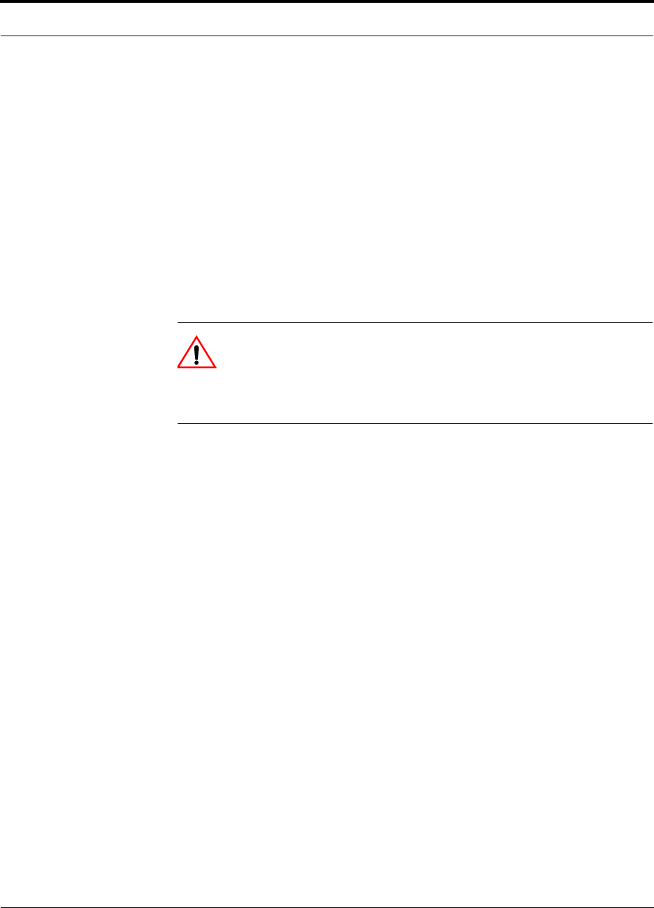
CAUTION: This format is used when a given action or omitted
action can cause or contribute to a hazardous condition. Damage to
the equipment can occur.
WARNING: This format is used when a given action or omitted action
can result in catastrophic damage to the equipment or cause injury to
the user.
Procedure
This format highlights a procedure.
1.4 Acronyms in this Manual
Acronym Definition
AGC automatic gain control
ALC automatic level control
AMPS Advanced Mobile Phone Service
AWS Advanced Wireless Services
BTS base transceiver station
Cat-5/6 Category 5 or Category 6 (twisted pair cable)
CDMA code division multiple access
CDPD cellular digital packet data
DAS distributed antenna system
dB decibel
dBm decibels relative to 1 milliwatt
DC direct current
DCS Digital Communications System
DL downlink
EDGE Enhanced Data Rates for Global Evolution
EGSM Extended Global Standard for Mobile Communications
EH Expansion Hub
GHz gigahertz
GPRS General Packet Radio Service

Help Hot Line (U.S. only): 1-800-530-9960 1-5
D-620003-0-20 Rev M CONFIDENTIAL
Acronyms in this Manual
GSM Groupe Speciale Mobile (now translated in English as Global Standard
for Mobile Communications)
Hz hertz
IF intermediate frequency
iDEN Integrated Digital Enhanced Network (Motorola variant of TDMA
wireless)
LAN local area network
LO local oscillator
LTE Long Term Evolution
mA milliamps
MBS microcellular base station
MH Main Hub
MHz megahertz
MMF multi-mode fiber
MTBF mean time between failures
NF noise figure
nm nanometer
OA&M operation, administration, and maintenance
PCS Personal Communication Services
PLL phase-locked loop
PLS path loss slope
PS Public Safety
RAU Remote Access Unit
RF radio frequency
RSSI received signal strength indicator
SC/APC fiber optic connector complying with NTT SC standard, angle-polished
SMA sub-miniature A connector (coaxial cable connector type)
SMF single-mode fiber
ST straight tip (fiber optic cable connector type)
ScTP screened twisted pair
TDMA time division multiple access
UL uplink; Underwriters Laboratories
uW microwatts
UMTS Universal Mobile Telecommunications System
UPS uninterruptable power supply
Wwatt
WCDMA wideband code division multiple access
Acronym Definition

Standards Conformance
1-6 InterReach Unison Installation, Operation, and Reference Manual
CONFIDENTIAL D-620003-0-20 Rev M
1.5 Standards Conformance
• Utilizes the TIA/EIA 568-A Ethernet cabling standards for ease of installation.
• Refer to Appendix B for compliance information.
1.6 Related Publications
• AdminManager User Manual, ADC part number 8810-10
•OpsConsole User Manual; ADC part number 8800-10
•FlexWave Focus Configuration, Installation, and Reference Manual; ADC part
number 8500-10
•LGCell Version 4.0 Installation, Operation, and Reference Manual; ADC part
number 8100-50
•Neutral Host System Planning Guide; ADC part number 9000-10
•Unison Release 5.1 Field Note, ADC FN03-007 (formerly, FN-024)
•Unison Release 5.4 Field Note, ADC FN04-002
•Unison Release 5.5 Field Note, ADC FN04-004
•Unison Release 5.6 Field Note, ADC FN05-001
•Unison Release 5.7.1 Field Note, ADC FN06-001
•Unison Release 5.8 Field Note, ADC FN08-001
•Cat-5/5E/6 Cabling Requirements for Unison Family Field Note, ADC FN04-001.

InterReach Unison Installation, Operation, and Reference Manual 2-1
D-620003-0-20 Rev M CONFIDENTIAL
SECTION 2 InterReach Unison System
Description
InterReach Unison is an intelligent fiber optic/Cat-5/5E/6 wireless networking system
designed to handle both wireless voice and data communications and provide
high-quality, ubiquitous, seamless access to the wireless network in any public or pri-
vate facility, including:
• Campus environments
• Airports
• Office buildings
• Shopping malls
• Hospitals
• Subways
• Public facilities (convention centers, sports venues, and so on.)
Unlike other wireless distribution alternatives, Unison is an intelligent, active system,
using microprocessors to enable key capabilities such as software-selectable band set-
tings, automatic gain control, ability to incrementally adjust downlink/uplink gain,
end-to-end alarming of all components and the associated cable infrastructure, and a
host of additional capabilities.
The Unison system supports major wireless standards and air interface protocols in
use around the world, including:
• Frequencies: 700 MHz, 800 MHz, 900 MHz, 1700 MHz, 1800 MHz, 1900 MHz,
2100 MHz
• Voice Protocols: AMPS, TDMA, CDMA, GSM, iDEN, LTE
• Data Protocols: CDPD, EDGE, GPRS, WCDMA, CDMA2000, 1xRTT, EV-DO,
LTE, and Paging

2-2 InterReach Unison Installation, Operation, and Reference Manual
CONFIDENTIAL D-620003-0-20 Rev M
Key System Features
•Superior RF performance, particularly in the areas of IP3 and noise figure.
•High downlink composite power and low uplink noise figure for support of a
large number of channels and larger coverage footprint per antenna.
•Software configurable Main and Expansion Hubs. Thus, the frequency band can
be configured in the field.
•Either single-mode or multi-mode fiber can be used, supporting flexible cabling
alternatives (in addition to standard Cat-5, Cat-5E, or Cat-6 screened twisted pair
[ScTP]). You can select the cabling type to meet the resident cabling infrastructure
of the facility and unique building topologies.
•Extended system “reach.” Using single-mode fiber, fiber runs can be as long as
6 kilometers (creating a total system “wingspan” of 12 kilometers). Alternately,
with multi-mode fiber, fiber runs can be as long as 1.5 kilometers. The Cat-5/5E/6
ScTP cable run can be up to 100 meters recommended maximum, or up to 170
meters when using a Cat-5 Extender.
•Flexible RF configuration capabilities, including:
• System gain:
– Ability to manually set gain in 1 dB steps, from 0 to 15 dB, on both down-
link and uplink.
•RAU:
– RAU uplink and downlink gain can be independently attenuated 10 dB.
– Uplink level control protects the system from input overload and can be
optimized for either a single operator or multiple operators/protocols.
– VSWR check on RAU reports if there is a disconnected antenna (all RAUs
except UMTS-1).
•Firmware Updates are downloaded (either locally or remotely) to operating sys-
tems when any modifications are made to the product, including the addition of
new software capabilities/services.
•Extensive OA&M capabilities, including fault isolation to the field replaceable
unit, automatic reporting of all fault and warning conditions, and user-friendly
graphical-user interface OA&M software packages.

Help Hot Line (U.S. only): 1-800-530-9960 2-3
D-620003-0-20 Rev M CONFIDENTIAL
System Hardware
2.1 System Hardware
The InterReach Unison system consists of three modular components:
• 19" rack-mountable Main Hub (connects to up to 4 Expansion Hubs)
• RF signal conversion to optical on the downlink; optical to RF on the uplink
• Microprocessor controlled (for alarms, monitoring, and control)
• Software configurable band
• Simplex interface to RF source
• System master – periodically polls all downstream units (Expansion
Hubs/RAUs) for system status, and automatically reports any fault or warning
conditions
• 19" rack-mountable Expansion Hub (connects to up to 8 Remote Access Units)
• Optical signal conversion to electrical on the downlink; electrical to optical on
the uplink
• Microprocessor controlled (for alarms, monitoring, and control)
• Software configurable band (based on command from Main Hub)
• Supplies DC power to RAU
•Remote Access Unit (RAU)
• Electrical signal conversion to RF on the downlink; RF to electrical on the
uplink
• Microprocessor controlled (for alarms, monitoring, and control)
• Protocol/band specific units
The minimum configuration of a Unison system is one Main Hub, one Expansion
Hub, and one RAU (1-1-1). The maximum configuration of a system is one Main
Hub, four Expansion Hubs, and 32 RAUs (1-4-32). You can combine multiple sys-
tems to provide larger configurations.
Figure 2-1 Unison System Hardware
System OA&M Capabilities
2-4 InterReach Unison Installation, Operation, and Reference Manual
CONFIDENTIAL D-620003-0-20 Rev M
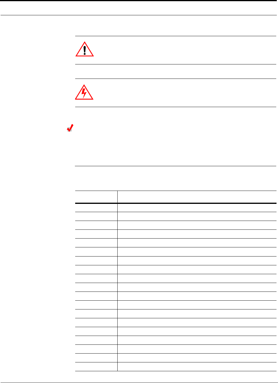
2.2 System OA&M Capabilities
The InterReach Unison is microprocessor controlled and contains firmware which
enables much of the OA&M functionality.
Complete alarming, down to the field replaceable unit (that is, Main Hub, Expansion
Hub, Remote Access Unit) and the cabling infrastructure, is available. All events
occurring in a system, defined as a Main Hub and all of its associated Expansion
Hubs and Remote Access Units, are automatically reported to the Main Hub. The
Main Hub monitors system status and communicates that status using the following
methods:
• Normally closed (NC) or normally open (NO) alarm contacts can be tied to stan-
dard alarm monitoring systems or directly to a base station for alarm monitoring.
• The Main Hub’s front panel serial port connects directly to a PC (for local access)
or to a modem (for remote access).
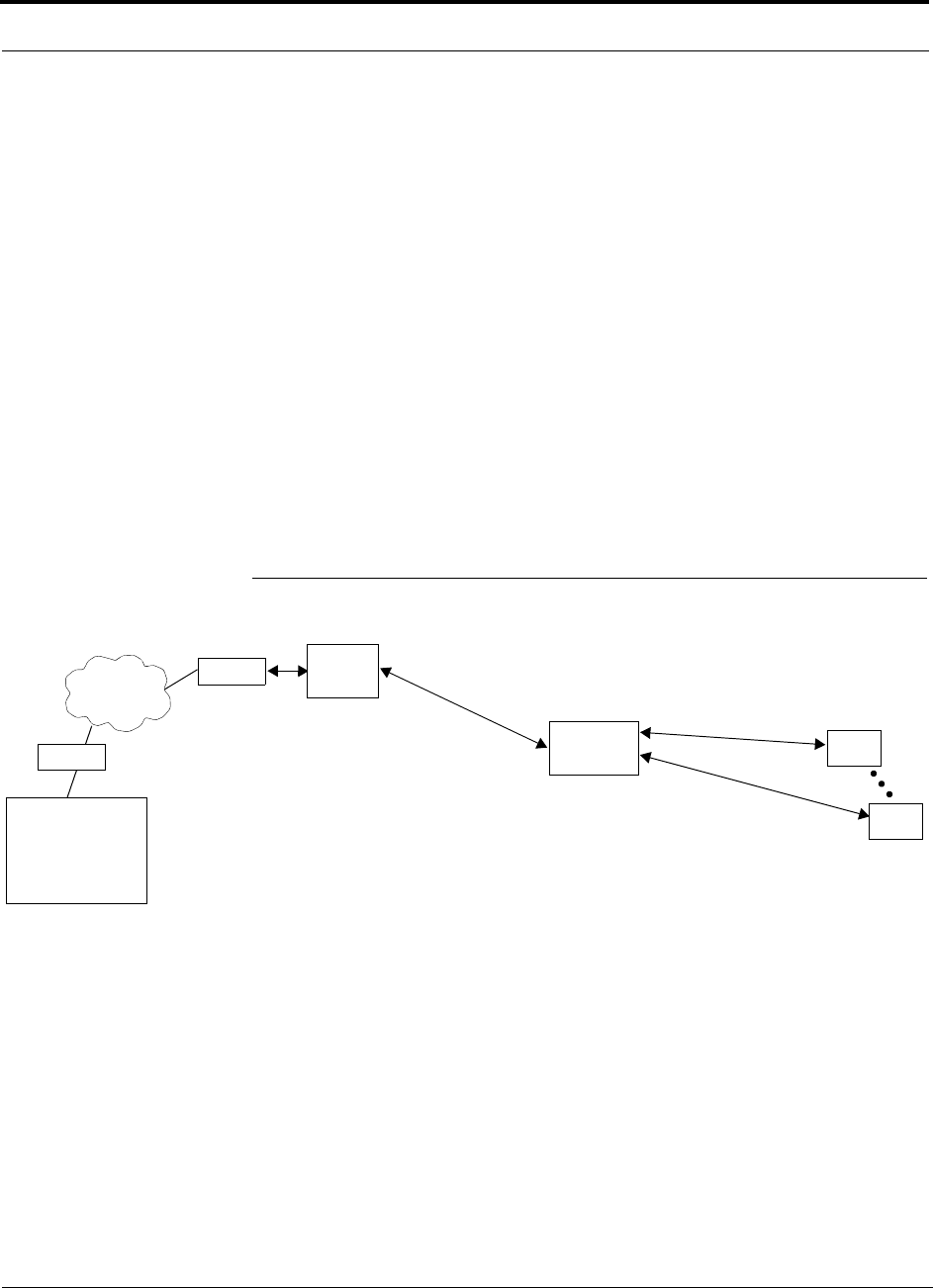
Figure 2-2 OA&M Communications
PSTN
RS-232
RS-232 Ethernet
PC/Laptop
running
Modem
Main Hub
Modem
Main Hub
RS-232
ENET/232
Converter
Cat-5/6
RS-232
SC/APC
Main Hub
SC/APC
RJ-45
Expansion Hub
RJ-45
Remote Access Unit
Fiber
Main Hub
AdminManager
or OpsConsole
Use AdminManager to configure
Use OpsConsole to monitor
and receive communications from
remote or local Unison systems.
or monitor a local Unison system.
Remotely, AdminManager can only
check system status. It cannot
receive modem calls.
TCP/IP

Help Hot Line (U.S. only): 1-800-530-9960 2-5
D-620003-0-20 Rev M CONFIDENTIAL
System OA&M Capabilities
ADC offers two OA&M packages: AdminManager and OpsConsole. Both run on a
PC/laptop.
• AdminManager communicates with one Main Hub, and its downstream units, at a
time. Using AdminManager connected locally or remotely, you can configure a
newly installed system, change system parameters, perform an end-to-end system
test, or query system status.
Refer to the AdminManager User Manual (PN 8810-10) for information about
installing and using the AdminManager software.
• OpsConsole lets you manage, monitor, and maintain multiple sites and systems
from a centralized remote location. This software is described in the OpsConsole
User Guide (PN 8800-10).
Table 2-1 lists the functional differences between AdminManager and OpsConsole.
Table 2-1 AdminManager and OpsConsole Functional Differences
Feature AdminManager OpsConsole
Installation Wizard Yes No
Local System Configuration Yes Yes
Remote System Configuration Yes Yes
Local Firmware Updating Yes No
Save unit information in a database No Yes
Network view of installed systems Yes Yes
Send dispatch message No Yes
Monitor multiple units No Yes
Scheduled polling No Yes
Windows-based GUI application Yes Yes
Runs on Windows 98 SE Yes No
Runs on Windows 2000 Yes Yes
Installation and configuration tool Yes No
Operation, Administration, and Management tool No Yes

System OA&M Capabilities
2-6 InterReach Unison Installation, Operation, and Reference Manual
CONFIDENTIAL D-620003-0-20 Rev M
Table 2-2 lists connectivity differences between AdminManager and OpsConsole.
Table 2-2 AdminManager and OpsConsole Connectivity Differences
Connectivity AdminManager OpsConsole
Direct RS-232 Yes (COM1 through
COM16) Yes
RS-232 Expansion Board Yes, if the expansion port
is in the range of COM1
through COM16
Yes
Modem (including RF modem) Yes Yes
Ethernet/232 serial hub Yes, if the remote COM
port is in the range of
COM1 through COM16
Yes
Line Sharing Switch after POTS Yes Yes
Help Hot Line (U.S. only): 1-800-530-9960 2-7
D-620003-0-20 Rev M CONFIDENTIAL
System OA&M Capabilities
2.2.1 OA&M Software
2.2.1.1 Configuring, Maintaining, and Monitoring Unison Locally
Each Main Hub, Expansion Hub, and RAU in the system constantly monitors itself
and its downstream units for internal fault and warning conditions. The results of this
monitoring are stored in memory and compared against new results.
The Expansion Hubs monitor their RAUs and store their status in memory. The Main
Hub monitors its Expansion Hubs and stores their status and the status of the RAUs in
its memory. When a unit detects a change in status, a fault or warning is reported.
Faults are indicated locally by red status LEDs, and both faults and warnings are
reported to the Main Hub and displayed on a PC/laptop, using the Main Hub’s serial
port, that is running the AdminManager software. Passive antennas connected to the
RAUs are not monitored automatically. Perform the System Test in order to retrieve
status information about antennas.
Using AdminManager locally, you can install a new system or new components,
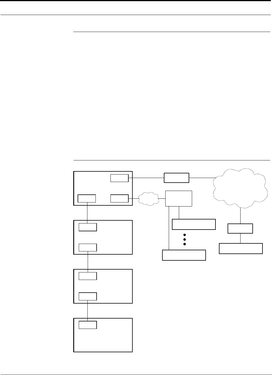
change system parameters, and query system status. Figure 2-3 illustrates how the
system reports its status to AdminManager.
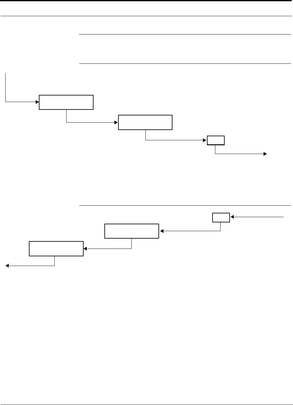
Figure 2-3 Local System Monitoring and Reporting
Main
Hub
Expansion
Hub
The Main Hub checks its own status and queries each
Expansion Hub for its status, which includes RAU status.
The Expansion Hub queries its own status
and polls each RAU for its status.
Each RAU passes its status to
the Expansion Hub.
• If a fault is detected, the
ALARM LED is red. If no fault
is detected, the LED is green.
The Expansion Hub queries status
of each RAU and compares it to
previously stored status.
• If a fault is detected, LEDs on
the front panel turn red.
The Main Hub queries
status of each Expansion Hub
and each RAU and compares
it to previously stored status.
• If a fault is detected, LEDs
on the front panel turn red.
PC/Laptop
running
AdminManager
Use AdminMan-
ager to query units
for their status or to
get current fault or
warning conditions.
RAU
RAU
System OA&M Capabilities
2-8 InterReach Unison Installation, Operation, and Reference Manual
CONFIDENTIAL D-620003-0-20 Rev M
2.2.1.2 Monitoring and Maintaining Unison Remotely
• Using AdminManager Remotely
You can use AdminManager remotely to call into the Main Hub and query current
status, change parameters, or command system end-to-end test. You cannot use
AdminManager to continuously monitor system state changes.
•Using OpsConsole Remotely
When monitoring the system remotely, any change of state within the system
causes the Main Hub to initiate an automatic call-out and report the system status
to the OpsConsole. The Main Hub calls out three times, each with a 45 second
interval. If the call is not acknowledged in these three tries, the Main Hub waits 15
minutes and continues the above sequence until the call is acknowledged.
Refer to the OpsConsole User Manual (PN 8800-10) for more information about
using OpsConsole for remote system monitoring.
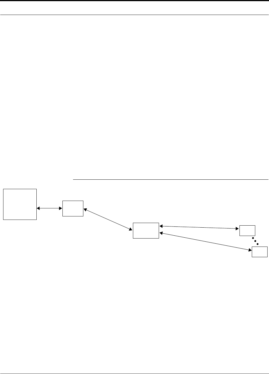
Figure 2-4 illustrates how the system reports its status to AdminManager and the
OpsConsole.
Figure 2-4 Remote System Monitoring and Reporting
Expansion
Hub
The Expansion Hub queries its own status
and polls each RAU for its status.
Each RAU passes its status to
the Expansion Hub.
• If a fault is detected, the
ALARM LED lights red. If no
fault is detected, the LED is
green.
The Expansion Hub queries
status of each RAU and com-
pares it to previously stored
status.
• If a fault is detected, LEDs on
the front panel turn red.
The Main Hub queries
status of each Expansion
Hub and each RAU and
compares it to previously
stored status.
• If a fault is detected,
LEDs on the front panel
turn red.
Use OpsConsole to com-
municate with one or more
remotely or locally installed
systems.
If a fault or warning condi-
tion is reported, the
OpsConsole graphical user
interface indicates the
problem. OpsConsole can
also send an e-mail and/or
page notification to desig-
nated recipients.
RAU
RAU
Modem
Modem
Main
Hub
PC
running
OpsConsole
The Main Hub checks its own status and queries each
Expansion Hub for its status, which includes RAU status.
PSTN
Help Hot Line (U.S. only): 1-800-530-9960 2-9
D-620003-0-20 Rev M CONFIDENTIAL
System OA&M Capabilities
2.2.2 Using Alarm Contacts
You can connect the DB-9 female connector on the rear panel of the Main Hub to a
local base station or to a daisy-chained series of Unison, LGCell, and/or FlexWave
Focus systems.
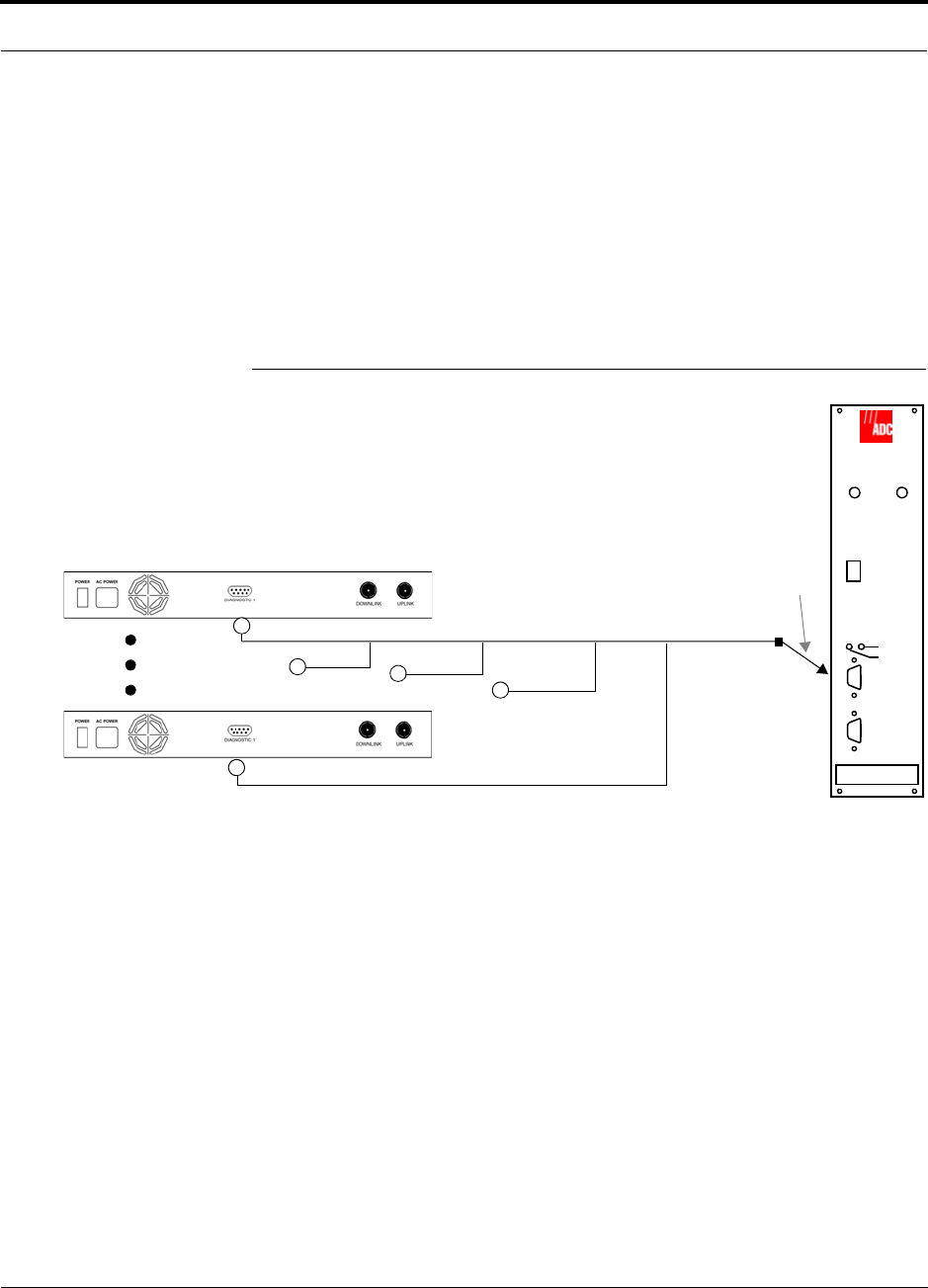
• When you connect FlexWave Focus or a BTS to Unison, the Unison Main Hub is
the output of the alarms (alarm source) and FlexWave Focus or the BTS is the
input (alarm sense). This is described in Section 7.7.1 on page 7-43. The following
figure shows using FlexWave Focus as the input of Unison contact closures.
Figure 2-5 Alarm Source
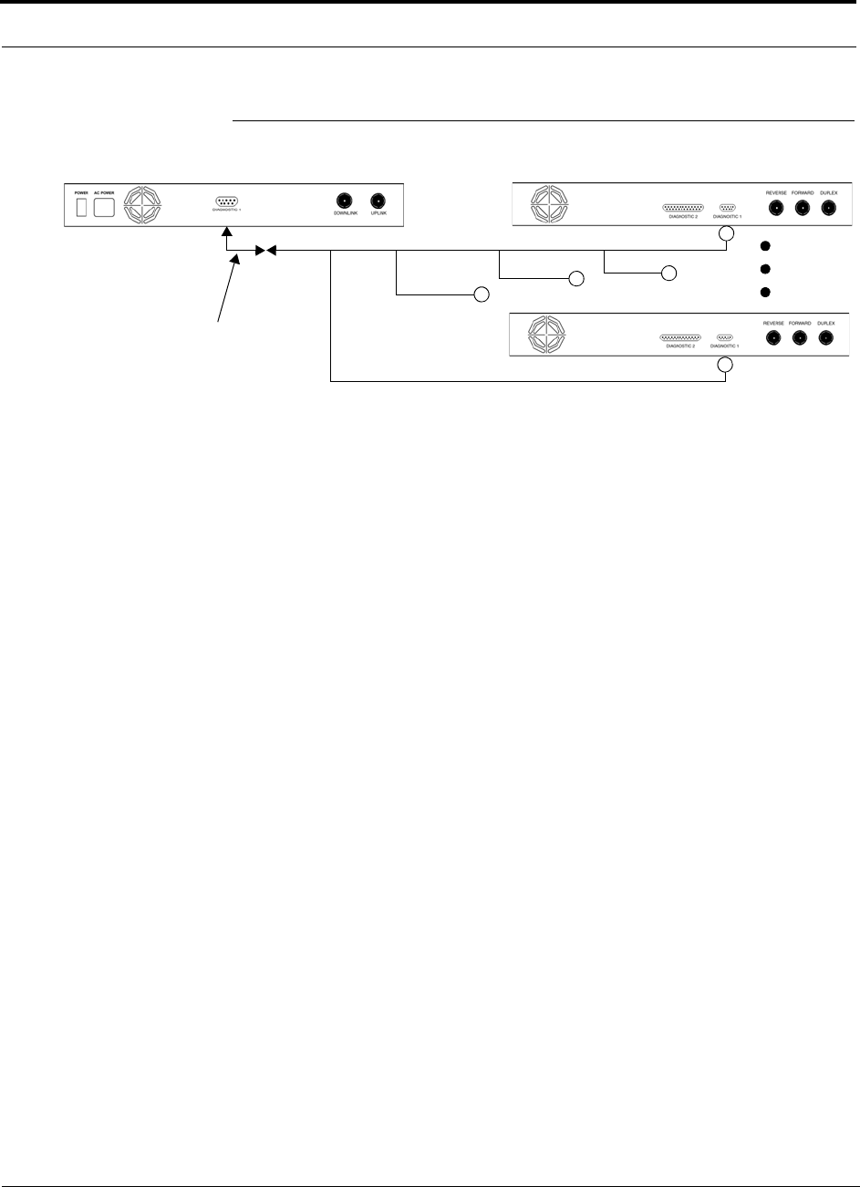
• When you connect LGCell to Unison, the Unison Main Hub is the input of the
alarms (alarm sense) and LGCell is the output (alarm source). This is described in
Section 7.7.2 on page 7-46
Unison Main Hub
RF OUT
DOWNLINK RF IN
UPLINK
FIBER
UPLINK
DOWNLINK
ALARM
RS-232C
FlexWave
Focus
RFM
Alarm
Sense
Alarm
Source
Alarm
Source
5-port Alarm Daisy-Chain Cable
9-pin Adapter
System OA&M Capabilities
2-10 InterReach Unison Installation, Operation, and Reference Manual
CONFIDENTIAL D-620003-0-20 Rev M
Figure 2-6 Alarm Sense.
Up to 5 LGCell Main HubsUnison Main Hub
Alarm
Sense Alarm
Source
Alarm
Source
Alarm Sense
Adapter Cable
5-port Alarm Daisy-Chain Cable
Help Hot Line (U.S. only): 1-800-530-9960 2-11
D-620003-0-20 Rev M CONFIDENTIAL
System Connectivity
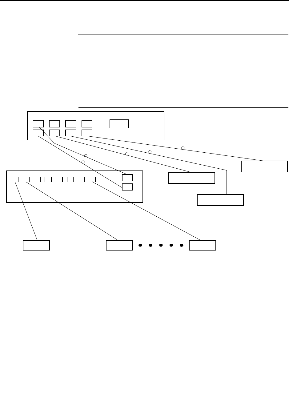
2.3 System Connectivity
The double star architecture of the Unison system, illustrated in Figure 2-7, provides
excellent system scalability and reliability. The system requires only one pair of
fibers for eight antenna points. This makes any system expansion, such as adding an
extra antenna for additional coverage, potentially as easy as pulling an extra twisted
pair.
Figure 2-7 Unison’s Double Star Architecture
Main Hub
RS-232
PORT 1 PORT 2 PORT 3 PORT 4
Expansion Hub Expansion Hub
Fiber
Expansion Hub
Expansion Hub
Cat-5/5E/6Cat-5/5E/6 Cat-5/5E/6
up to 8 RAUs per Expansion Hub
RAU RAU RAU
System Operation
2-12 InterReach Unison Installation, Operation, and Reference Manual
CONFIDENTIAL D-620003-0-20 Rev M
2.4 System Operation
Figure 2-8 Downlink (Base Station to Wireless Devices)
Figure 2-9 Uplink (Wireless Devices to Base Station)
Main Hub
RAU
The Main Hub receives downlink RF signals
from a base station using coaxial cable.
The Main Hub converts the RF signals to IF, then
to optical signals and sends them to Expansion
Hubs (up to four) using optical fiber cable.
The Expansion Hub converts the optical sig-
nals to electrical signals and sends them to
RAUs (up to eight) using Cat-5/5E/6 ScTP
The RAU converts the IF signals
to RF and sends them to passive
antennas using coaxial cable.
Expansion Hub
Main Hub
RAU
The Main Hub sends
uplink RF signals to a
base station via coaxial
cable.
The Main Hub receives
the optical signals from
the Expansion Hubs (up
to four) via optical fiber
cable and converts
them to RF signals.
The Expansion Hub
receives the IF signals
from the RAUs (up to
eight) via Cat-5/5E/6
ScTP cable and con-
verts them to optical
The RAU receives uplink RF
signals from the passive
antenna via coaxial cable and
converts them to IF signals.
Expansion Hub

Help Hot Line (U.S. only): 1-800-530-9960 2-13
D-620003-0-20 Rev M CONFIDENTIAL
System Specifications
2.5 System Specifications
Table 2-3 System Specifications
Parameter Main Hub Expansion Hub Remote Access Unit
RF Connectors 2 N-type, female 8 shielded RJ-45, female
(Cat-5/5E/6) 1 shielded RJ-45, female
(Cat-5/5E/6)
1 SMA, male (coaxial)
External Alarm Con-
nector
(contact closure)
1 9-pin D-sub, female 1 9-pin D-sub, female
(UNS-EH-2 only) —
Serial Interface Con-
nector 1 RS-232 9-pin D-sub, male — —
Fiber Connectors* 4 Pair, SC/APC 1 Pair, SC/APC —
LED Alarm and
Status Indicators Unit Status (1 pair):
•Power
• Main Hub Status
Downstream Unit Status
(1 pair per fiber port):
•Link
• E-Hub/RAU
Unit Status (1 pair):
•Power
• E-Hub Status
Fiber Link Status (1 pair):
•DL Status
•UL Status
RAU/Link Status
(1 pair per RJ-45 port):
•Link
•RAU
Unit Status (1 pair):
•Link
•Alarm
AC Power (Volts)** Rating: 100–240V, 0.5A,
50–60 Hz
Operating Range: 85–250V,
2.4–0.8A, 47–63 Hz
Rating: 115/230V, 5/2.5A,
50–60 Hz
Operating Range:
90–132V/170–250V
auto-ranging,
2.2–1.5A/1.2–0.8A, 47–63 Hz
—
DC Power (Volts) — — 36V (from the Expansion Hub)
Power Consumption
(W)** 30 4 RAUs: 120 typ/148 max
4 RAUs & 4 Extenders:
137 typ/172 max
8 RAUs: 170 typ/212 max
8 RAUs & 8 Extenders:
204 typ/260 max
16 max (from Expansion Hub)
Enclosure Dimensions†
(height × width ×
depth)
44.5 mm × 438 mm × 305 mm
(1.75 in. × 17.25 in. × 12 in.)
I U
89 mm × 438 mm × 305 mm
(3.5 in. × 17.25 in. × 12 in.)
2 U
44 mm × 305 mm × 158 mm
(1.7 in. × 12 in. × 6.2 in.)
Weight < 3 kg (< 6.5 lb) < 5 kg (< 11 lb) < 1 kg (< 2 lb)
MTBF 106,272 hours 92,820 hours 282,207 hours

System Specifications
2-14 InterReach Unison Installation, Operation, and Reference Manual
CONFIDENTIAL D-620003-0-20 Rev M
2.5.1 InterReach Unison Wavelength and Laser Power
Table 2-4 shows wavelength and laser power according to UL testing per IEC 60
825-1.
Table 2-4 InterReach Unison Wavelength and Laser Power
2.5.2 Environmental Specifications
Table 2-5 Environmental Specifications
*It is critical to system performance that only SC/APC fiber connectors are used throughout the fiber network, including fiber distribution panels.
** For Japan, see separate addendum – Japan Specification Document.
†Excluding angle-brackets for 19'' rack mounting of hubs.
Note: Expansion Hub typical power consumption assumes that the Cat-5/6 cable length is no more than 100 meters without a Cat-5 Extender and
no more than 170 meters with a Cat-5 Extender.
Wavelength
Measured Output Power
Main Hub Expansion Hub
1310 nm ±20 nm 458 uW 1.8 mW
Parameter Main Hub and Expansion Hub RAU
Operating Temperature 0° to +45°C (+32° to +113°F) –25° to +45°C (–13° to +113°F)
Non-operating Temperature –20° to +85°C (–4° to +185°F) –25° to +85°C (–13° to +185°F)
Operating Humidity; non-condensing 5% to 95% 5% to 95%

Help Hot Line (U.S. only): 1-800-530-9960 2-15
D-620003-0-20 Rev M CONFIDENTIAL
System Specifications
2.5.3 Operating Frequencies
Table 2-6 Operating Frequencies
Freq.
Band Unison
Band Description
RF Passband
Downlink (MHz) Uplink (MHz)
PCS PCS6 A, D & B Band
(35 MHz)
1930–1965 1850–1885
PCS PCS7 D,B,E & F Band
(30 MHz)
1945–1975 1865–1895
PCS PCS8 E, F & C Band
(25 MHz)
1965–1990 1885–1910
PCS PCS9 A4/A5/D/B/E 1935-1970 1855-1890
PCS PCS10 A5/D/B/E/F 1940-1975 1860-1895
PCS PCS11 D/B/E/F/C2 1945-1982.5 1865-1902.5
PCS PCS12 B4/B5/E/F/C 1955-1990 1875-1910
DCS DCS1 DCS1 Band 1805–1842.5 1710–1747.5
DCS DCS2 DCS2 Band 1842.5–1880 1747.5–1785
DCS DCS4 DCS4 Band 1815–1850 1720–1755
Cellular CELL – 869–894 824–849
iDEN iDEN – 851–869 806–824
UMTS UMTS1 – 2110–2145 1920–1955
UMTS UMTS2 – 2125–2160 1935–1970
UMTS UMTS3 – 2135–2170 1945–1980
UMTS UMTS1 Japan 2110–2130 1920–1940
UMTS UMTS2 Japan 2130–2150 1940–1960
UMTS UMTS 3 Japan 2150–2170 1960–1980
AWS AWS1 – 2110-2145 1710-1745
AWS AWS2 – 2120-2155 1720-1755
PS 700 PS700 – 763-776 793-806
700 LTE 700 UC 700 (Upper C)
Band 746-757 776-787

System Specifications
2-16 InterReach Unison Installation, Operation, and Reference Manual
CONFIDENTIAL D-620003-0-20 Rev M
2.5.4 RF End-to-End Performance
Table 2-7 through Table 2-12 list the RF end-to-end performance of each protocol
when using 2 km of single-mode fiber or 1 km of multi-mode fiber.
Cellular 800 MHz
iDEN 800 MHz
Table 2-7 Cellular RF End-to-End Performance
Parameter
2 km of SMF 1 km of MMF
Typical Typical
Downlink Uplink Downlink Uplink
Average gain with 75 m Cat-5/5E/6 at 25°C (77°F)*
*The system gain is adjustable in 1 dB steps from 0 to 15 dB, and the gain of each RAU can be attenuated 10 dB in one step.
15 dB 15 dB 15 dB 15 dB
Ripple with 75 m Cat-5/5E/6 3 dB 3.5 dB 3 dB 3.5 dB
Output IP3 40 dBm 37 dBm
Input IP3 –7 dBm –10 dBm
Output 1 dB Compression Point 27 dBm 27 dBm
Noise Figure with 1 MH – 1 EH – 8 RAUs configuration 15 dB 15 dB
Noise Figure with 1 MH – 4 EHs – 32 RAUs configuration 21 dB 21 dB
Table 2-8 iDEN RF End-to-End Performance
Parameter
2 km of SMF 1 km of MMF
Typical Typical
Downlink Uplink Downlink Uplink
Average gain with 75 m Cat-5/5E/6 at 25°C (77°F)*
*The system gain is adjustable in 1 dB steps from 0 to 15 dB, and the gain of each RAU can be attenuated 10 dB in one step.
15 dB 15 dB 15 dB 15 dB
Ripple with 75 m Cat-5/5E/6 2 dB 3 dB 2 dB 3 dB
Output IP3 38 dBm 38 dBm
Input IP3 –7 dBm –10 dBm
Output 1 dB Compression Point 26 dBm 26 dBm
Noise Figure with 1 MH – 1 EH – 8 RAUs configuration 17 dB 17 dB
Noise Figure with 1 MH – 4 EHs – 32 RAUs configuration 23 dB 23 dB

Help Hot Line (U.S. only): 1-800-530-9960 2-17
D-620003-0-20 Rev M CONFIDENTIAL
System Specifications
GSM/EGSM 900 MHz
DCS 1800 MHz
Table 2-9 GSM/EGSM RF End-to-End Performance
Parameter
2 km of SMF 1 km of MMF
Typical Typical
Downlink Uplink Downlink Uplink
Average gain with 75 m Cat-5/5E/6 at 25°C (77°F)*
*The system gain is adjustable in 1 dB steps from 0 to 15 dB, and the gain of each RAU can be attenuated 10 dB in one step.
15 dB 15 dB 15 dB 15 dB
Ripple with 75 m Cat-5/5E/6 3 dB 4 dB 3 dB 4 dB
Output IP3 38 dBm 38 dBm
Input IP3 –7 dBm –10 dBm
Output 1 dB Compression Point 26 dBm 26 dBm
Noise Figure with 1 MH – 1 EH – 8 RAU configuration 16 dB 16 dB
Noise Figure with 1 MH – 4 EH – 32 RAU configuration 22 dB 22 dB
Table 2-10 DCS RF End-to-End Performance
Parameter
2 km of SMF 1 km of MMF
Typical Typical
Downlink Uplink Downlink Uplink
Average gain with 75 m Cat-5/5E/6 at 25°C (77°F)*
*The system gain is adjustable in 1 dB steps from 0 to 15 dB, and the gain of each RAU can be attenuated 10 dB in one step. UNS-UMTS-2 has a 1 dB attenuator in the RAU.
15 dB 15 dB 15 dB 15 dB
Downlink ripple with 75 m Cat-5/5E/6 2 dB 2 dB
Uplink ripple for center 35 MHz of DCS1 and DCS2,
Full band for DCS3 & DCS4 with 75 m Cat-5/5E/6 2 dB 2 dB
Uplink gain roll off for Full band of DCS1 and DCS2 with
75 m Cat-5/5E/6 2 dB 2 dB
Output IP3 38 dBm 37 dBm
Input IP3 –12 dBm –14 dBm
Output 1 dB Compression Point 26 dBm 26 dBm
Noise Figure with 1 MH – 1 EH – 8 RAU configuration 17 dB 17 dB
Noise Figure with 1 MH – 4 EH – 32 RAU configuration 23 dB 23 dB

System Specifications
2-18 InterReach Unison Installation, Operation, and Reference Manual
CONFIDENTIAL D-620003-0-20 Rev M
PCS 1900 MHz
UMTS 2.1 GHz
Table 2-11 PCS RF End-to-End Performance
Parameter
2 km of SMF 1 km of MMF
Typical Typical
Downlink Uplink Downlink Uplink
Average gain with 75 m Cat-5/5E/6 at 25°C (77°F)*
*The system gain is adjustable in 1 dB steps from 0 to 15 dB, and the gain of each RAU can be attenuated 10 dB in one step.
15 dB 15 dB 15 dB 15 dB
Ripple with 75 m Cat-5/5E/6 2.5 dB 3 dB 2.5 dB 3 dB
Output IP3 38 dBm 36.5 dBm
Input IP3 –12 dBm –14 dBm
Output 1 dB Compression Point 26 dBm 26 dBm
Noise Figure with 1 MH – 1 EH – 8 RAUs configuration 16 dB 16 dB
Noise Figure with 1 MH – 4 EHs – 32 RAUs configuration 22 dB 22 dB
Table 2-12 UMTS RF End-to-End Performance**
Parameter
2 km of SMF 1 km of MMF
Typical Typical
Downlink Uplink Downlink Uplink
Average gain with 75 m Cat-5/5E/6 at 25°C (77°F) *
*The system gain is adjustable in 1 dB steps from 0 to 15 dB, and the gain of each RAU can be attenuated 10 dB in one step.
** For Japan, see separate addendum – Japan Specification Document.
15 dB 15 dB 15 dB 15 dB
Ripple with 75 m Cat-5/5E/6 2.5 dB 4 dB 2.5 dB 4 dB
Output IP3 37 dBm 36 dBm
Input IP3 –12 dBm –12 dBm
Output 1 dB Compression Point 26 dBm 26 dBm
Noise Figure with 1 MH – 1 EH – 8 RAUs configuration 16 dB 16 dB
Noise Figure with 1 MH – 4 EHs – 32 RAUs configuration 22 dB 22 dB

Help Hot Line (U.S. only): 1-800-530-9960 2-19
D-620003-0-20 Rev M CONFIDENTIAL
System Specifications
AWS 1.7/2.1 GHz
Public Safety 700 MHz
Table 2-13 AWS RF End-to-End Performance
Parameter
2 km of SMF 1 km of MMF
Typical Typical
Downlink Uplink Downlink Uplink
Average gain with 75 m Cat-5/5E/6 at 25°C (77°F) *
*The system gain is adjustable in 1 dB steps from 0 to 15 dB, and the gain of each RAU can be attenuated 10 dB in one step.
15 dB 15 dB 15 dB 15 dB
Ripple with 75 m Cat-5/5E/6 2 dB 2 dB 2 dB 2 dB
Output IP3 38 dBm 36 dBm
Input IP3 –12 dBm –14 dBm
Output 1 dB Compression Point 26 dBm 26 dBm
Noise Figure with 1 MH – 1 EH – 8 RAUs configuration 17 dB 17 dB
Noise Figure with 1 MH – 4 EHs – 32 RAUs configuration 23 dB 23 dB
Table 2-14 Public Safety 700 MHz RF End-to-End Performance
Parameter
2 km of SMF 1 km of MMF
Typical Typical
Downlink Uplink Downlink Uplink
Average gain with 75 m Cat-5/5E/6 at 25°C (77°F) *
*The system gain is adjustable in 1 dB steps from 0 to 15 dB, and the gain of each RAU can be attenuated 10 dB in one step.
15 dB 15 dB 15 dB 15 dB
Ripple with 75 m Cat-5/5E/6 2 dB 3 dB 2 dB 3 dB
Output IP3 38 dBm 36 dBm
Input IP3 –7 dBm –10 dBm
Output 1 dB Compression Point 26 dBm 26 dBm
Noise Figure with 1 MH – 1 EH – 8 RAUs configuration 16 dB 16 dB
Noise Figure with 1 MH – 4 EHs – 32 RAUs configuration 22 dB 22 dB

System Specifications
2-20 InterReach Unison Installation, Operation, and Reference Manual
CONFIDENTIAL D-620003-0-20 Rev M
700 MHz LTE
Table 2-15 700 MHz (Upper C) RF End-to-End Performance
Parameter
2 km of SMF 1 km of MMF
Typical Typical
Downlink Uplink Downlink Uplink
Average gain with 75 m Cat-5/5E/6 at 25°C (77°F) *
*The system gain is adjustable in 1 dB steps from 0 to 15 dB, and the gain of each RAU can be attenuated 10 dB in one step.
15 dB 15 dB 15 dB 15 dB
Ripple with 75 m Cat-5/5E/6 2 dB 3 dB 2 dB 3 dB
Output IP3 38 dBm 36 dBm
Input IP3 –7 dBm –10 dBm
Output 1 dB Compression Point 26 dBm 26 dBm
Noise Figure with 1 MH – 1 EH – 8 RAUs configuration 16 dB 16 dB
Noise Figure with 1 MH – 4 EHs – 32 RAUs configuration 22 dB 22 dB
InterReach Unison Installation, Operation, and Reference Manual 3-1
D-620003-0-20 Rev M CONFIDENTIAL
SECTION 3 Unison Main Hub
The Main Hub distributes downlink RF signals from a base station, repeater, or Flex-
Wave Focus system to up to four Expansion Hubs, which in turn distribute the signals
to up to 32 Remote Access Units. The Main Hub also combines uplink signals from
the associated Expansion Hubs.
Figure 3-1 Main Hub in a Unison System
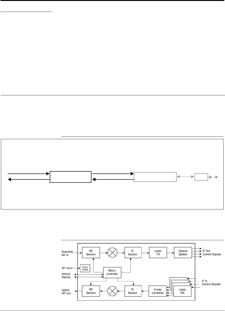
Figure 3-2 shows a detailed view of the major RF and optical functional blocks of the
Main Hub.
Figure 3-2 Main Hub Block Diagram
Unison Main Hub Unison Expansion Hub RAU
Downlink Path: The Main Hub receives downlink RF signals from a base station, repeater, or FlexWave Focus system via
coaxial cable. It converts the signals to IF then to optical and sends them to up to four Expansion Hubs via fiber optic cable.
The Main Hub also sends OA&M communication to the Expansion Hubs via the fiber optic cable. The Expansion Hubs, in
turn, communicate the OA&M information to the RAUs via Cat-5/5E/6 cable.
Uplink Path: The Main Hub receives uplink optical signals from up to four Expansion Hubs via fiber optic cables. It converts
the signals to IF then to RF and sends them to a base station, repeater, or FlexWave Focus system via coaxial cable.
The Main Hub also receives status information from the Expansion Hubs and all RAUs via the fiber optic cable.
Downlink to Main Hub
Uplink from Main Hub
Downlink from Main Hub
Uplink to Main Hub
Main Hub Front Panel
3-2 InterReach Unison Installation, Operation, and Reference Manual
CONFIDENTIAL D-620003-0-20 Rev M
3.1 Main Hub Front Panel
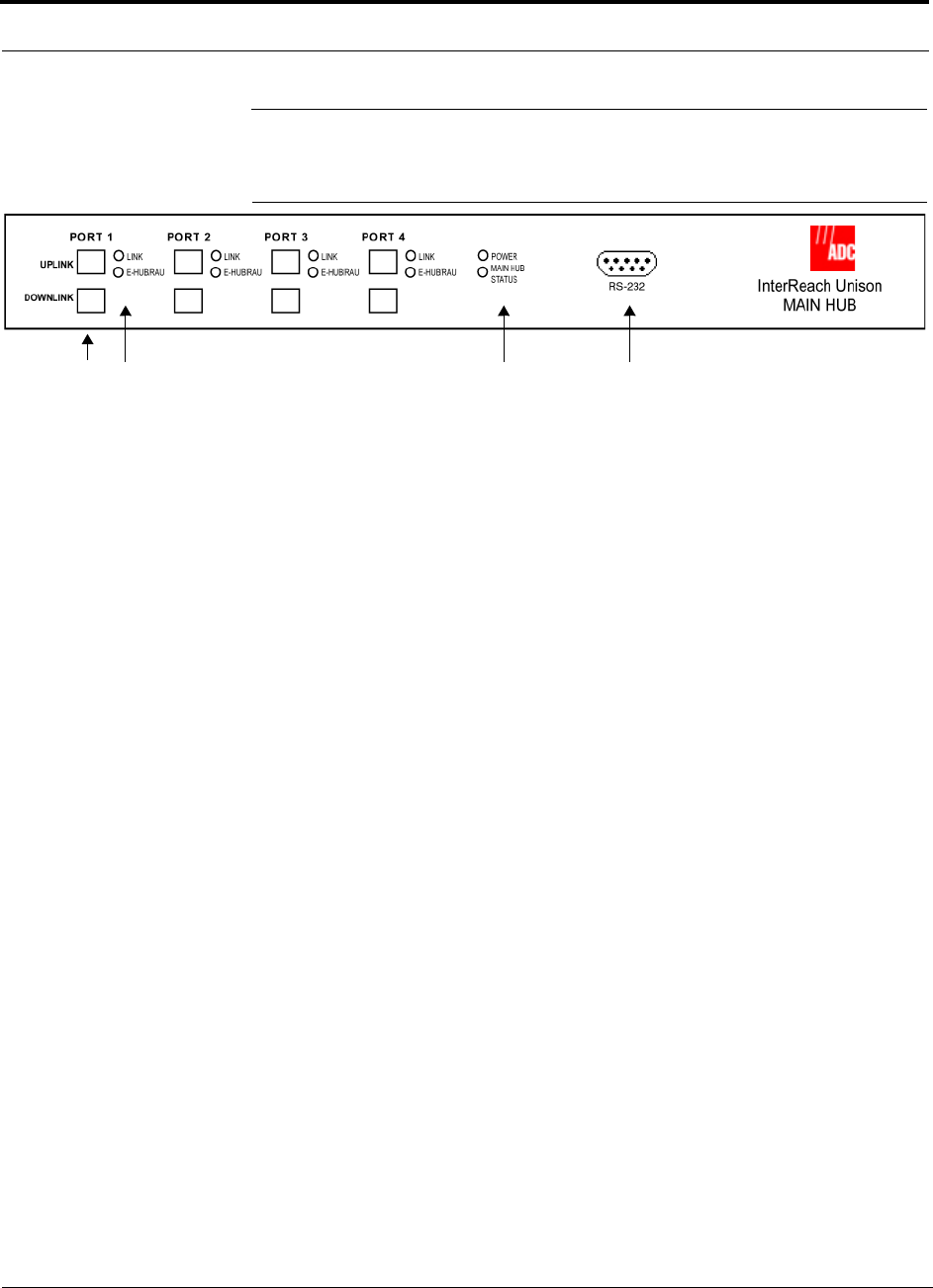
Figure 3-3 Main Hub Front Panel
1. Four fiber optic ports (labeled PORT 1, PORT 2, PORT 3, PORT 4)
• One standard female SC/APC connector per port for MMF/SMF input (labeled
UPLINK)
• One standard female SC/APC connector per port for MMF/SMF output
(labeled DOWNLINK)
2. Four sets of fiber port LEDs (one set per port)
• One LED per port for port link status (labeled LINK)
• One LED per port for downstream unit status (labeled E-HUB/RAU)
3. One set of unit status LEDs
• One LED for unit power status (labeled POWER)
• One LED for unit status (labeled MAIN HUB STATUS)
4. One 9-pin D-sub male connector for system communication and diagnostics using
a PC/laptop or modem (labeled RS-232)
1234
Help Hot Line (U.S. only): 1-800-530-9960 3-3
D-620003-0-20 Rev M CONFIDENTIAL
Main Hub Front Panel
3.1.1 Optical Fiber Uplink/Downlink Ports
The optical fiber uplink/downlink ports transmit and receive optical signals between
the Main Hub and up to four Expansion Hubs using industry-standard SMF or MMF
cable. There are four fiber ports on the front panel of the Main Hub; one port per
Expansion Hub. Each fiber port has two female SC/APC connectors:
• Optical Fiber Uplink Connector
This connector (labeled UPLINK) is used to receive the uplink optical signals from
an Expansion Hub.
• Optical Fiber Downlink Connector
This connector (labeled DOWNLINK) is used to transmit the downlink optical sig-
nals to an Expansion Hub.
CAUTION: To avoid damaging the Main Hub’s fiber connector ports,
use only SC/APC fiber cable connectors when using either single-mode
or multi-mode fiber. Additionally, it is critical to system performance
that only SC/APC fiber connectors are used throughout the fiber network, includ-
ing fiber distribution panels.
3.1.2 Communications RS-232 Serial Connector
Remote Monitoring
Use a standard serial cable to connect a modem to the 9-pin D-sub male serial con-
nector for remote monitoring or configuring. The cable typically has a DB-9 female
and a DB-25 male connector. Refer to Appendix A.4 on page A-3 for the cable pin-
out.
Local Monitoring
Use a null modem cable to connect a laptop or PC to the 9-pin D-sub male serial con-
nector for local monitoring or configuring. The cable typically has a DB-9 female
connector on both ends. Refer to Appendix A.5 on page A-4 for the cable pinout.

Main Hub Front Panel
3-4 InterReach Unison Installation, Operation, and Reference Manual
CONFIDENTIAL D-620003-0-20 Rev M
3.1.3 LED Indicators
The unit’s front panel LEDs indicate faults and commanded or fault lockouts. The
LEDs do not indicate warnings or whether the system test has been performed. Only
use the LEDs to provide basic information or as a backup when you are not using
AdminManager.
Upon power up, a Main Hub goes through a five-second test to check the LED lamps.
During this time, the LEDs blink through the states shown in Table 3-2, letting you
visually verify that the LED lamps and the firmware are functioning properly.
Main Hubs ship without a band programmed into them. After the equipment is
installed, cables connected, and powered up, an unprogrammed Main Hub LEDs dis-
plays as follows:
•MAIN HUB STATUS LED: Red
•LINK LED: Green
•E-HUB/RAU LED: Red
If the LEDs do not display as above, refer to Table 3-1 on page 3-5, Table 3-2 on
page 3-6, and/or Section 9 for troubleshooting using the LEDs.
Help Hot Line (U.S. only): 1-800-530-9960 3-5
D-620003-0-20 Rev M CONFIDENTIAL
Main Hub Front Panel
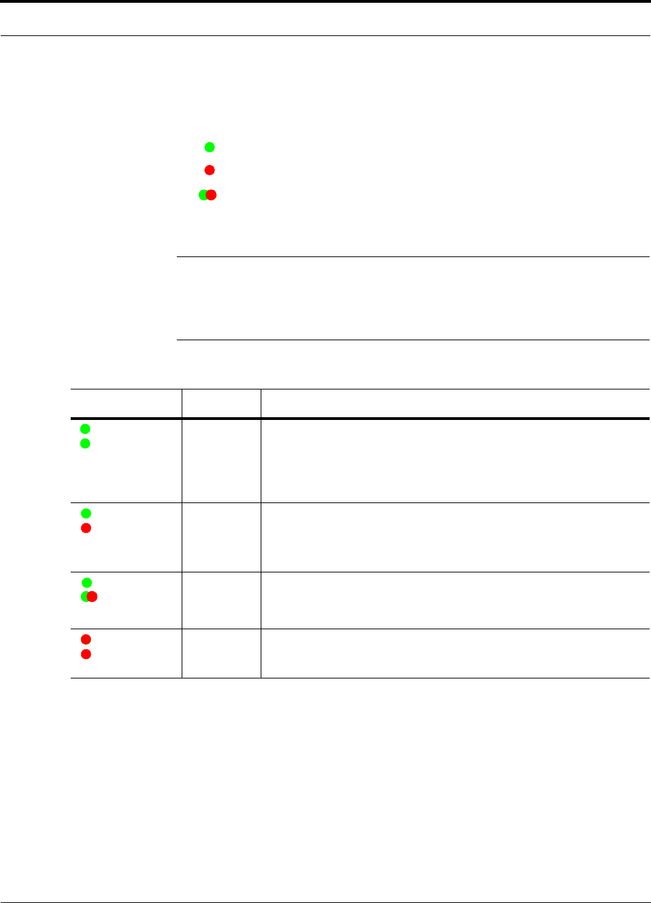
Unit Status LEDs
The Main Hub status LEDs can be in one of the states shown in Table 3-1. These
LEDs can be:
steady green
steady red
blinking green/red (alternating green/red)
There is no off state when the unit’s power is on.
NOTE: AdminManager or OpsConsole must be used for troubleshooting
the system. Only use LEDs as backup or for confirmation. However, if there
are communications problems within the system, the LEDs may provide
additional information that is not available using AdminManager.
l
Table 3-1 Main Hub Status LED States
LED State Indicates
Green
Green
• The Main Hub is connected to power and all power supplies are operat-
ing.
• The Main Hub is not reporting a fault; but the system test may need to
be performed or a warning could exist (use AdminManager to deter-
mine).
Green
Red
• The Main Hub is connected to power and all power supplies are operat-
ing.
• The Main Hub is reporting a fault or lockout condition, or the band is
not programmed.
Green
Alternating
Green/Red
• The Main Hub is connected to power and all power supplies are operat-
ing.
• The Main Hub input signal level is too high.
Red
Red
• One or more power supplies in the hub are out-of-specification.
POWER
MAIN HUB
STATUS
POWER
MAIN HUB
STATUS
POWER
MAIN HUB
STATUS
POWER
MAIN HUB
STATUS
Main Hub Front Panel
3-6 InterReach Unison Installation, Operation, and Reference Manual
CONFIDENTIAL D-620003-0-20 Rev M
Port LEDs
The Main Hub has one pair of fiber port LEDs for each of the four fiber optic ports.
The LED pairs can be in one of the states shown in Table 3-2. These LEDs can be:
off
steady green
steady red
The port LEDs indicate the status of the Expansion Hub and RAUs; however, they do
not indicate which particular unit has a fault (that is, the Expansion Hub vs. one of its
RAUs).
Table 3-2 Main Hub Port LED States
LED State Indicates
Off
Off • The Expansion Hub is not connected.
Green
Green • The Expansion Hub is connected, communications are normal.
• There are no faults from Expansion Hub or any connected RAU.
Red
Off • There was a loss of communications with the Expansion Hub.
• The Expansion Hub is disconnected.
Green
Red • The Expansion Hub is connected.
• A fault or lockout was reported by the Expansion Hub or any connected RAU.
LINK
E-HUB/RAU
LINK
E-HUB/RAU
LINK
E-HUB/RAU
LINK
E-HUB/RAU
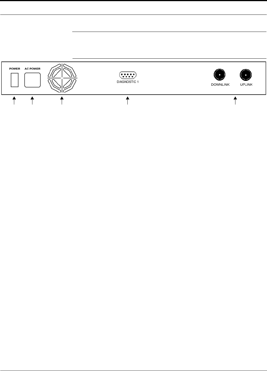
Help Hot Line (U.S. only): 1-800-530-9960 3-7
D-620003-0-20 Rev M CONFIDENTIAL
Main Hub Rear Panel
3.2 Main Hub Rear Panel
Figure 3-4 Main Hub Rear Panel
1. Power On/Off switch
2. AC power cord connector
3. Fan exhaust vent
4. One 9-pin D-sub female connector for alarm contact monitoring (labeled
DIAGNOSTIC 1)
5. Two N-type, female connectors:
• Downlink (labeled DOWNLINK)
• Uplink (labeled UPLINK)
1 2 3 4 5

Main Hub Rear Panel
3-8 InterReach Unison Installation, Operation, and Reference Manual
CONFIDENTIAL D-620003-0-20 Rev M
3.2.1 Main Hub Rear Panel Connectors
3.2.1.1 9-pin D-sub Connector
The 9-pin D-sub connector (labeled DIAGNOSTIC 1) provides contacts for fault and
warning system alarm monitoring.
Table 3-3 lists the function of each pin on the 9-pin D-sub connector.
Table 3-3 9-pin D-sub Connector Functions
This interface can both generate contact alarms and sense a single external alarm con-
tact.
3.2.1.2 N-type Female Connectors
There are two N-type female connectors on the rear panel of the Main Hub:
• The DOWNLINK connector receives downlink RF signals from a repeater, local
base station, or FlexWave Focus system.
• The UPLINK connector transmits uplink RF signals to a repeater, local base sta-
tion, or FlexWave Focus system.
CAUTION:The UPLINK and DOWNLINK ports cannot handle a DC power
feed from the base station. If DC power is present, a DC block must be used
or the hub may be damaged.
Pin Function
1 Alarm Input Ground
2 Reserved
3 Reserved
4 Warning Contact (positive connection)
5 Warning Contact (negative connection)
6 DC Ground (common)
7 Fault Contact (positive connection)
8 Alarm Input
9 Fault Contact (negative connection)

Help Hot Line (U.S. only): 1-800-530-9960 3-9
D-620003-0-20 Rev M CONFIDENTIAL
Main Hub Specifications
3.3 Main Hub Specifications
Table 3-4 Main Hub Specifications
Specification** Description
Enclosure Dimensions (H × W × D): 44.5 mm × 438 mm × 305 mm (1.75 in. × 17.25 in. × 12 in.)
1 U
Weight < 3 kg (< 6.5 lb)
Operating Temperature** 0° to +45°C (+32° to +113°F)
Non-operating Temperature** –20° to +85°C (–4° to +185°F)
Operating Humidity, non-condensing 5% to 95%
External Alarm Connector
(contact closure) 1 9-pin D-sub, female
Maximum: 40 mA @ 40V DC
Typical: 4 mA @ 12V DC
Serial Interface Connector 1 RS-232 9-pin D-sub, male
Fiber Connectors 4 Pair, SC/APCa
a. It is critical to system performance that only SC/APC fiber connectors are used throughout the fiber network, including
fiber distribution panels.
** For Japan, refer to separate addendum - Japan Specification Document.
RF Connectors 2 N-type, female
LED Fault and Status Indicators Unit Status (1 pair):
•Power
• Main Hub Status
Downstream Unit/Link Status (1 pair per fiber port):
•Link
• E-Hub/RAU
AC Power Rating: 100–240V, 0.5A, 50–60 Hz
Operating Range: 85–250V, 2.4–0.8A, 47–63 Hz
Power Consumption (W) 30
MTBF 106,272 hours

Faults, Warnings, and Status Messages
3-10 InterReach Unison Installation, Operation, and Reference Manual
CONFIDENTIAL D-620003-0-20 Rev M
3.4 Faults, Warnings, and Status Messages
3.4.1 Description
The Main Hub monitors and reports changes or events in system performance to:
• Ensure that the fiber receivers, amplifiers, and IF/RF path in the Main Hub are
functioning properly.
• Ensure that Expansion Hubs and Remote Access Units are connected and function-
ing properly.
An event is classified as a fault, warning, or status message.
• Faults are service impacting.
• Warnings indicate a possible service impact.
• Status messages are generally not service impacting.
The Main Hub periodically queries attached Expansion Hubs and their Remote
Access Units for their status. Both faults and warnings are reported to a connected
PC/laptop running the AdminManager software or to the optional remote OpsCon-
sole. Only faults are indicated by LEDs.
For more information, refer to:
• page 9-6 for Main Hub faults.
• page 9-17 for Main Hub warnings.
• page 9-22 for Main Hub status messages.
• page 9-27 for troubleshooting Main Hub LEDs.
3.4.2 View Preference
AdminManager 2.04 or higher allows you to select what type of events to be dis-
played.

Help Hot Line (U.S. only): 1-800-530-9960 3-11
D-620003-0-20 Rev M CONFIDENTIAL
Faults, Warnings, and Status Messages
To modify the setting, select View J Preference and select the desired choice. You
can change the setting either while connected to a system or offline. If there is a con-
nection to a system, after the you click OK, AdminManager refreshes and updates the
tree view according to the new setting. Note that the setting is strictly visual and only
in AdminManager. There is no affect on the hardware itself. The same setting is car-
ried with AdminManager and applied to any hardware AdminManager is connected
to. By default, event filtering is set to “Enable viewing of Faults only”.
The only exception when the vent filtering is ignored is during the Install/Configure
command. All events are displayed regardless of the event filtering setting. This
ensures a smooth installation.

Faults, Warnings, and Status Messages
3-12 InterReach Unison Installation, Operation, and Reference Manual
CONFIDENTIAL D-620003-0-20 Rev M
This page is intentionally left blank.
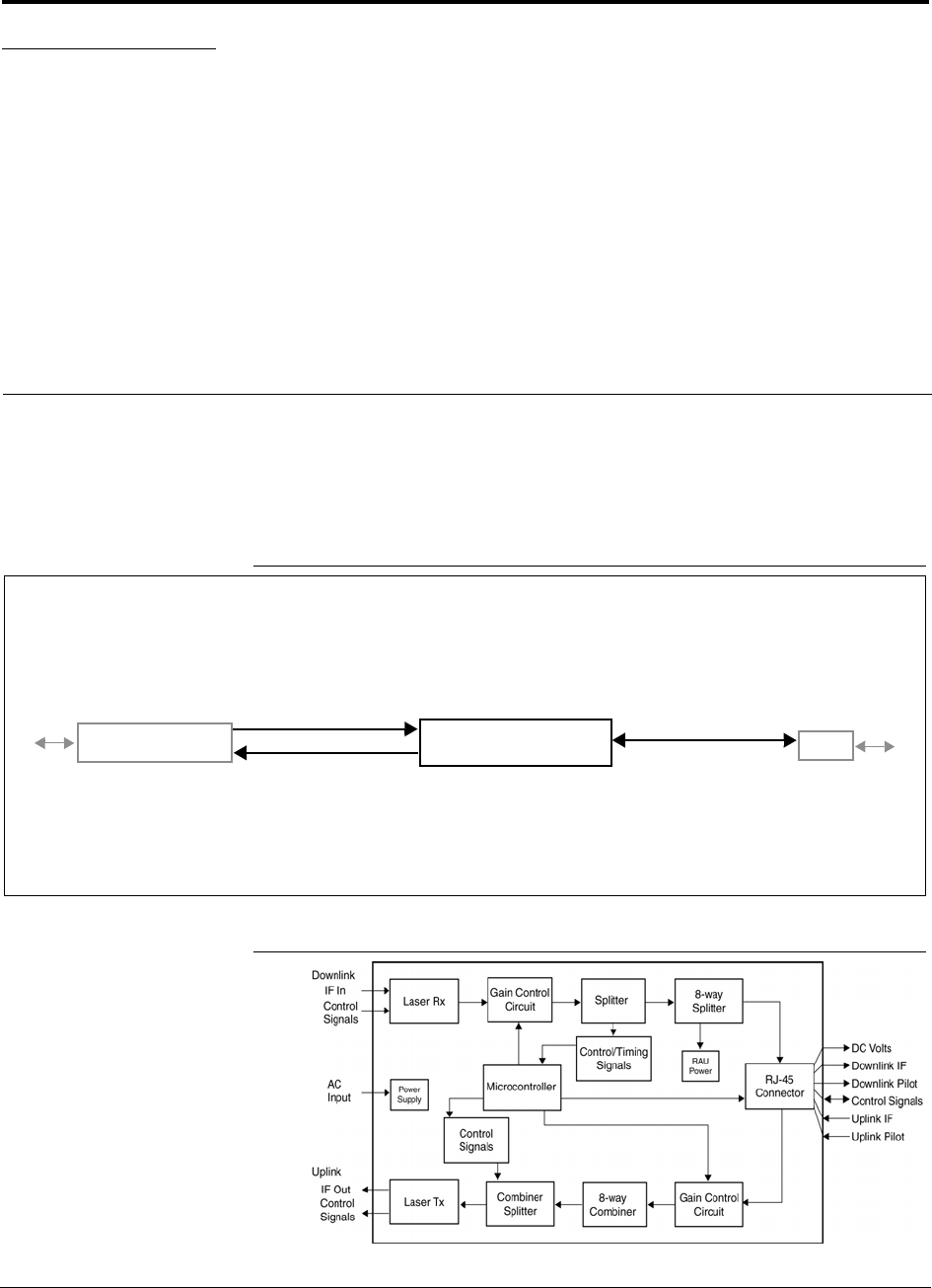
InterReach Unison Installation, Operation, and Reference Manual 4-1
D-620003-0-20 Rev M CONFIDENTIAL
SECTION 4 Unison Expansion Hub
The Expansion Hub interfaces between the Main Hub and the Remote Access Unit(s)
by converting optical signals to electrical signals and vice versa. It also supplies con-
trol signals and DC power to operate the Remote Access Unit(s) as well as passes sta-
tus information from the RAUs to the Main Hub.
Figure 4-1 Expansion Hub in a Unison System
Figure 4-2 Expansion Hub Block Diagram
Unison Expansion Hub
Unison Main Hub RAU
Downlink Path: The Expansion Hub receives downlink optical signals from the Main Hub via fiber optic cable. It converts
the signals to electrical and sends them to up to eight Remote Access Units (RAUs) via Cat-5/5E/6 cables.
Also, the Expansion Hub receives configuration information from the Main Hub via the fiber optic cable and relays it to the
RAUs via the Cat-5/5E/6 cable.
Uplink Path: The Expansion Hub receives uplink IF signals from up to eight RAUs via Cat-5/5E/6 cables. It converts the
signals to optical and sends them to a Main Hub via fiber optic cable.
Also, the Expansion Hub receives RAU status information via the Cat-5/5E/6 cable and sends it and its own status informa-
tion to the Main Hub via the fiber optic cable.
Downlink to Expansion Hub
Uplink from Expansion Hub
Downlink from Expansion Hub
Uplink to Expansion Hub
From
Main Hub
To RAU
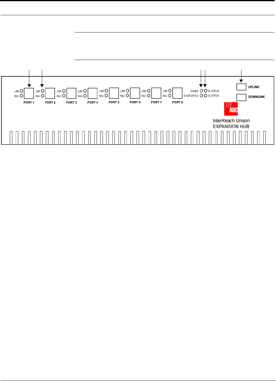
Expansion Hub Front Panel
4-2 InterReach Unison Installation, Operation, and Reference Manual
CONFIDENTIAL D-620003-0-20 Rev M
4.1 Expansion Hub Front Panel
Figure 4-3 Expansion Hub Front Panel
1. Eight standard Cat-5/5E/6 ScTP cable, RJ-45 shielded connectors (labeled PORT
1, 2, 3, 4, 5, 6, 7, 8)
2. Eight sets of RJ-45 port LEDs (one set per port)
• One LED per port for link status (labeled LINK)
• One LED per port for downstream unit status (labeled RAU)
3. One set of unit status LEDs
• One LED for unit power status (labeled POWER)
• One LED for unit status (labeled E-HUB STATUS)
4. One set of fiber connection status LEDs
• One LED for fiber downlink status (labeled DL STATUS)
• One LED for fiber uplink status (labeled UL STATUS)
5. One fiber optic port which has two connectors
• One standard female SC/APC connector for MMF/SMF output (labeled
UPLINK)
• One standard female SC/APC connector for MMF/SMF input (labeled
DOWNLINK)
1 2 3 4 5
Help Hot Line (U.S. only): 1-800-530-9960 4-3
D-620003-0-20 Rev M CONFIDENTIAL
Expansion Hub Front Panel
4.1.1 RJ-45 Connectors
The eight RJ-45 connectors on the Expansion Hub are for the Cat-5/5E/6 ScTP cables
used to transmit and receive signals to and from RAUs. Use shielded RJ-45 connec-
tors on the Cat-5/5E/6 cable.
NOTE: For system performance, it is important to use only Cat-5/5E/6 ScTP
(screened twisted pair) cable with shielded RJ-45 connectors.
Cat-5/5E/6 cable also delivers DC electrical power to the RAUs. The Expansion
Hub’s DC voltage output is 36V DC nominal. A current limiting circuit protects the
Expansion Hub if any port draws excessive power.
4.1.2 Optical Fiber Uplink/Downlink Connectors
The optical fiber uplink/downlink port transmits and receives optical signals between
the Expansion Hub and the Main Hub using industry-standard SMF or MMF cable.
The fiber port has two female SC/APC connectors:
• Optical Fiber Uplink Connector
This connector (labeled UPLINK) is used to transmit (output) uplink optical signals
to the Main Hub.
• Optical Fiber Downlink Connector
This connector (labeled DOWNLINK) is used to receive (input) downlink optical sig-
nals from the Main Hub.
CAUTION: To avoid damaging the Expansion Hub’s fiber connector
ports, use only SC/APC fiber cable connectors. Additionally, use only
SC/APC fiber connectors throughout the fiber network, including fiber
distribution panels. This is critical for ensuring system performance.
4.1.3 LED Indicators
The unit’s front panel LEDs indicate fault conditions and commanded or fault lockouts.
The LEDs do not indicate warnings or whether the system test has been performed.
Only use the LEDs to provide basic information or as a backup when you are not using
AdminManager.
Upon power up, the Expansion Hub goes through a five-second test to check the LED
lamps. During this time, the LEDs blink through the states shown in Table 4-2, letting
you visually verify that the LED lamps and the firmware are functioning properly.
NOTE: Refer to Section 9 for troubleshooting using the LEDs.
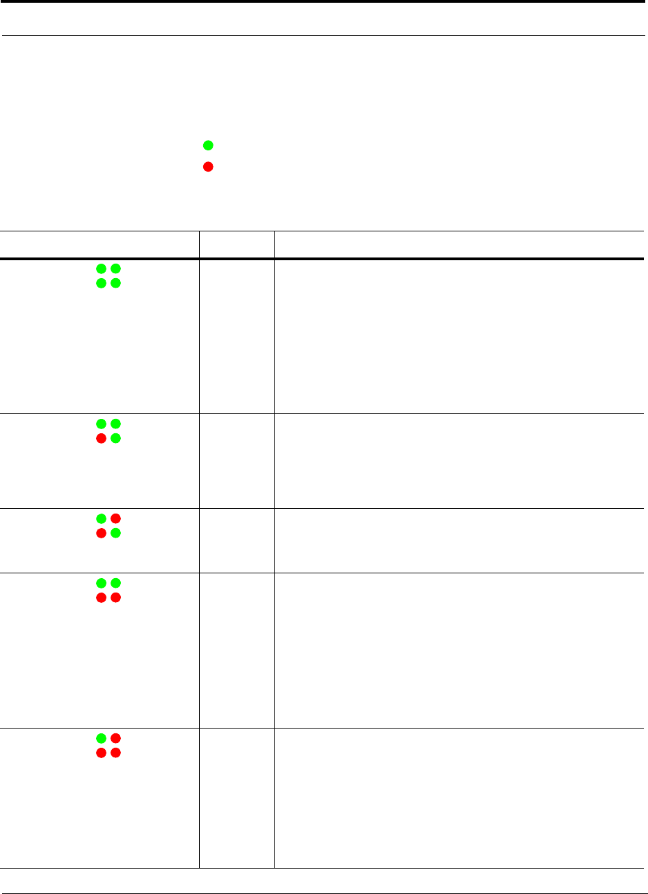
Expansion Hub Front Panel
4-4 InterReach Unison Installation, Operation, and Reference Manual
CONFIDENTIAL D-620003-0-20 Rev M
Unit Status and DL/UL Status LEDs
The Expansion Hub unit status and DL/UL status LEDs can be in one of the states
shown in Table 4-1. These LEDs can be:
steady green
steady red
There is no off state when the unit’s power is on.
Table 4-1 Expansion Hub Unit Status and DL/UL Status LED States
LED State Indicates
Green / Green
Green / Green
• The Expansion Hub is connected to power and all power supplies are
operating.
• The Expansion Hub is not reporting a fault or lockout condition; but
the system test may need to be performed or a warning condition
could exist (use AdminManager to determine this).
• Optical power in is above minimum (the Main Hub is connected)
although the cable optical loss may be greater than recommended
maximum.
• Optical power out (uplink laser) is normal and communications with
the Main Hub are normal.
Green / Green
Red / Green
• Optical power in is above minimum (the Main Hub is connected)
although the cable optical loss may be greater than recommended
maximum.
• Optical power out (uplink laser) is normal and communications with
the Main Hub are normal.
• The Expansion Hub is reporting a fault or commanded lockout.
Green / Red
Red / Green
• A fault condition was detected, optical power in is below minimum.
(the Main Hub is not connected, is not powered, or the Main Hub’s
downlink laser has failed, or the downlink fiber is disconnected or
damaged.)
Green / Green
Red / Red
• The Expansion Hub is reporting a fault condition.
• Optical power in is above minimum (Main Hub is connected)
although the cable optical loss may be greater than recommended
maximum.
• Optical power out is below minimum (Expansion Hub uplink laser
has failed; unable to communicate with Main Hub). UL STATUS LED
state must be checked within the first 90 seconds after power on. If
initially green, then red after 90 seconds, it means that there is no
communication with the Main Hub. If red on power up, replace the
Expansion Hub.
Green / Red
Red / Red
• Optical power in is below minimum (the Main Hub is not connected,
is not powered, or the Main Hub’s downlink laser has failed, or the
downlink fiber is disconnected or damaged.)
• Optical power out is below minimum (the Expansion Hub uplink
laser has failed; is unable to communicate with the Main Hub).
UL STATUS LED state must be checked within the first 90 seconds
after power on. If initially green, then red after 90 seconds, it means
that there is no communication with the Main Hub. If red on power
up, the uplink laser has failed, replace the Expansion Hub.
POWER
E-HUB STATUS DL STATUS
UL STATUS
POWER
E-HUB STATUS DL STATUS
UL STATUS
POWER
E-HUB STATUS DL STATUS
UL STATUS
POWER
E-HUB STATUS DL STATUS
UL STATUS
POWER
E-HUB STATUS DL STATUS
UL STATUS
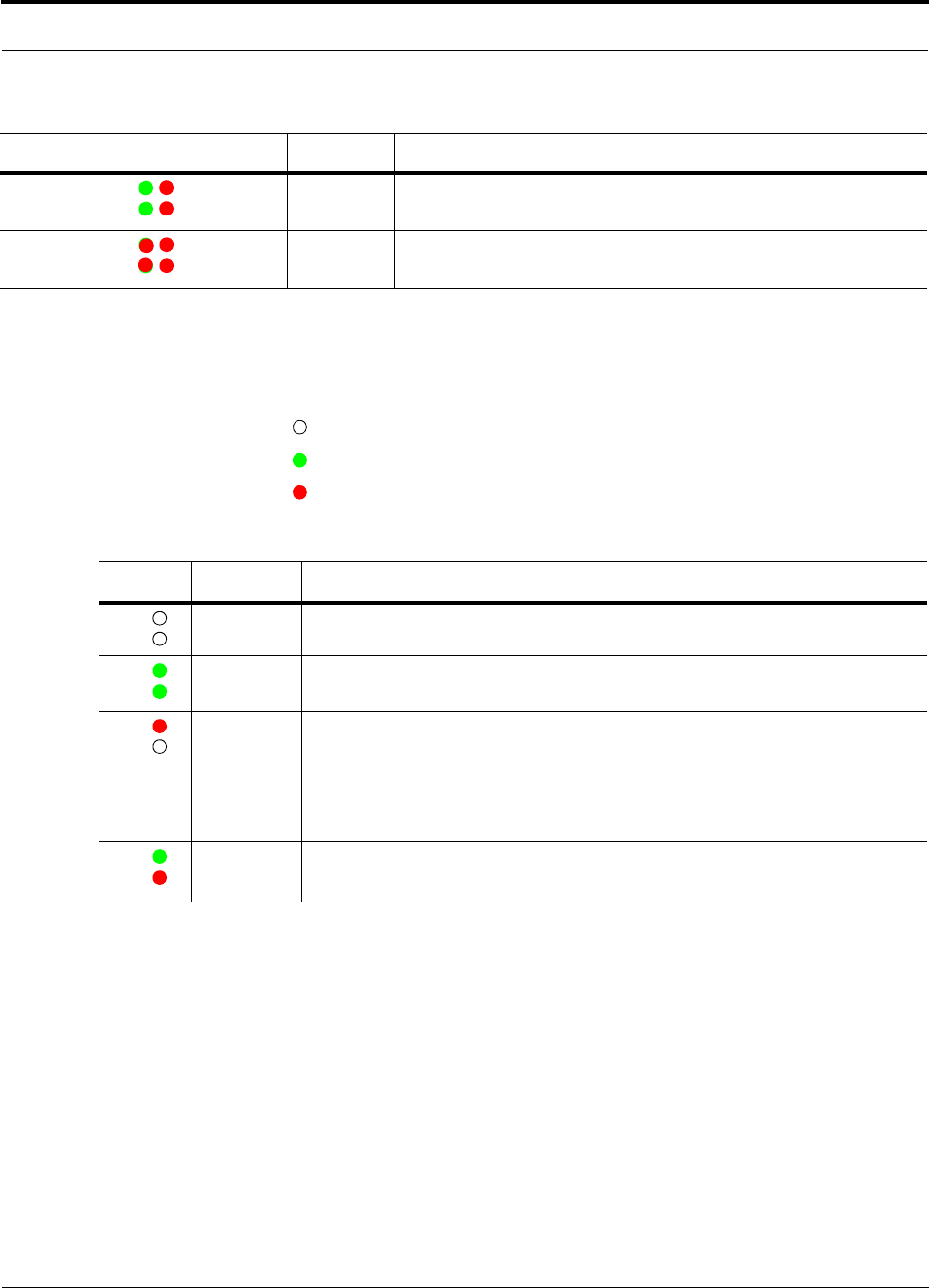
Help Hot Line (U.S. only): 1-800-530-9960 4-5
D-620003-0-20 Rev M CONFIDENTIAL
Expansion Hub Front Panel
Port LEDs
The Expansion Hub has one pair of port LEDs for each of the eight RJ-45 ports. The
port LEDs can be in one of the states shown in Table 4-2. These LEDs can be:
off
steady green
steady red
Green / Red
Green / Red
• Expansion Hub is in factory test mode, return it to the factory.
Red/ Red
Red/ Red
• One or more power supplies are out of specification. The hub needs to
be replaced.
Table 4-2 Expansion Hub Port LED States
LED State Indicates
Off
Off • The RAU is not connected.
Green
Green • The RAU is connected.
• No faults from the RAU.
Red
Off • The RAU was disconnected.
• The RAU is not communicating.
• The RAU port power is tripped.
• 36 VDC is shutdown due to an EH over-temperature condition.
Green
Red • The RAU is connected.
• The RAU is reporting a fault or lockout condition.
Table 4-1 Expansion Hub Unit Status and DL/UL Status LED States
LED State Indicates
POWER
E-HUB STATUS DL STATUS
UL STATUS
POWER
E-HUB STATUS DL STATUS
UL STATUS
LINK
RAU
LINK
RAU
LINK
RAU
LINK
RAU
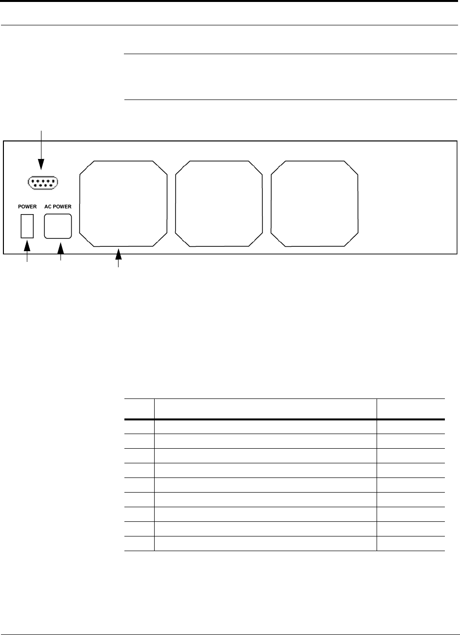
Expansion Hub Rear Panel
4-6 InterReach Unison Installation, Operation, and Reference Manual
CONFIDENTIAL D-620003-0-20 Rev M
4.2 Expansion Hub Rear Panel
Figure 4-4 Expansion Hub Rear Panel
1. Power on/off switch
2. AC power cord connector
3. Three air exhaust vents
4. DB-9 connector (UNS-EH-2 specific)
Table 4-3 DB-9 Pin Connectors
This interface can both generate contact alarms and sense a single external alarm con-
tact.
Pin Connection Signal Name
1N/C N/A
2 +5V through a 10K Ohm resistor. Input to micro controller ALARM3
3 +5V through a 10K Ohm resistor. Input to micro controller ALARM1
4 GND N/A
5 +5V through a 10K Ohm resistor. Input to micro controller) ALARM2
6N/C N/A
7N/C N/A
8 GND N/A
9 GND N/A
123
4

Help Hot Line (U.S. only): 1-800-530-9960 4-7
D-620003-0-20 Rev M CONFIDENTIAL
Faults, Warnings, and Status Messages
4.3 Faults, Warnings, and Status Messages
This interface monitors the output contact closures from a Universal Power Supply
(UPS). Verify the output contact closure state (normally closed or normally open) of
the UPS, and set the appropriate contact definition using AdminManager.
• Faults are service impacting.
• Warnings indicate a possible service impact.
• Status messages are generally not service impacting.
NOTE: You can select what type of events AdminManager displays. Refer
to Section 3.4.2, “View Preference,” on page 3-10.
Both fault and warning conditions of the Expansion Hub and attached RAUs are
reported to the Main Hub. Only faults are indicated by LEDs.
For more information, refer to:
• page 9-10 for Expansion Hub faults.
• page 9-20 for Expansion Hub warnings.
• page 9-24 for Expansion Hub status messages.
• page 9-30 for troubleshooting Expansion Hub LEDs.

Expansion Hub Specifications
4-8 InterReach Unison Installation, Operation, and Reference Manual
CONFIDENTIAL D-620003-0-20 Rev M
4.4 Expansion Hub Specifications
Table 4-4 Expansion Hub Specifications
Specification Description
Enclosure Dimensions (H × W × D) 89 mm × 438 mm × 305 mm (3.5 in. × 17.25 in. × 12 in.)
2U
Weight < 5 kg (< 11 lb)
Operating Temperaturec0° to +45°C (+32° to +113°F)
Non-operating Temperaturec–20° to +85°C (–4° to +185°F)
Operating Humidity, non-condensing 5% to 95%
Cat-5/5E/6 Connectorsa
a. It is important that you use only Cat-5/5E/6 ScTP cable with shielded RJ-45 connectors.
8 shielded RJ-45, female (Cat-5/6)
Fiber Connectorsb
b. It is critical to system performance that only SC/APC fiber connectors are used throughout the fiber network, including
fiber distribution panels.
c. For Japan, see separate addendum - Japan Specification Document.
1 Pair, SC/APC
LED Alarm and Status Indicators Unit Status (1 pair):
•Power
• E-Hub Status
Fiber Link Status (1 pair):
•DL Status
•UL Status
RAU/Link Status (1 pair per RJ-45 port):
•Link
•RAU
AC Power (Volts) (47–63 Hz) Rating: 115/230V, 5/2.5A, 50–60 Hz
Operating Range: 90–132V/170–250V auto-ranging,
2.2–1.5A/1.2–0.8A, 47–63 Hz
Power Consumption (W) 4 RAUs: 120 typical/148 max
4 RAUs & 4 Extenders: 137 typical/172 max
8 RAUs: 170 typical/212 max
8 RAUs & 8 Extenders: 204 typical/260 max
MTBF 92,820 hours
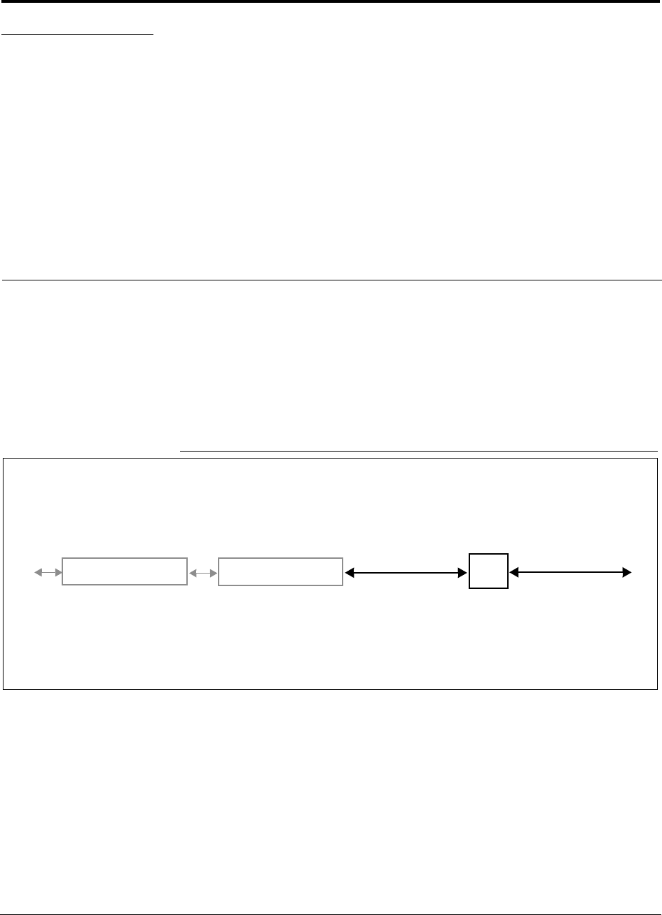
InterReach Unison Installation, Operation, and Reference Manual 5-1
D-620003-0-20 Rev M CONFIDENTIAL
SECTION 5 Unison Remote Access Unit
The Remote Access Unit (RAU) is an active transceiver that connects to an Expan-
sion Hub using industry-standard Cat-5/5E/6 screened twisted pair (ScTP) cable,
which delivers RF signals, configuration information, and electrical power to the
RAU.
An RAU passes RF signals between an Expansion Hub and an attached passive
antenna where the signals are transmitted to wireless devices.
Figure 5-1 Remote Access Unit in a Unison System
Unison Expansion Hub RAU
Downlink Path: The RAU receives downlink IF signals from an Expansion Hub via Cat-5/5E/6 cable. It converts the sig-
nals to RF and sends them to a passive RF antenna via coaxial cable.
Also, the RAU receives configuration information from the Main Hub via the Cat-5/5E/6 cable.
Uplink Path: The RAU receives uplink RF signals from a passive RF antenna via coaxial cable. It converts the signals to IF
and sends them to an Expansion Hub via Cat-5/5E/6 cable.
Also, the RAU sends its status information to the Expansion Hub via the Cat-5/5E/6 cable.
Downlink to RAU
Uplink from RAU
Unison Main Hub Downlink to antenna
Uplink from antenna
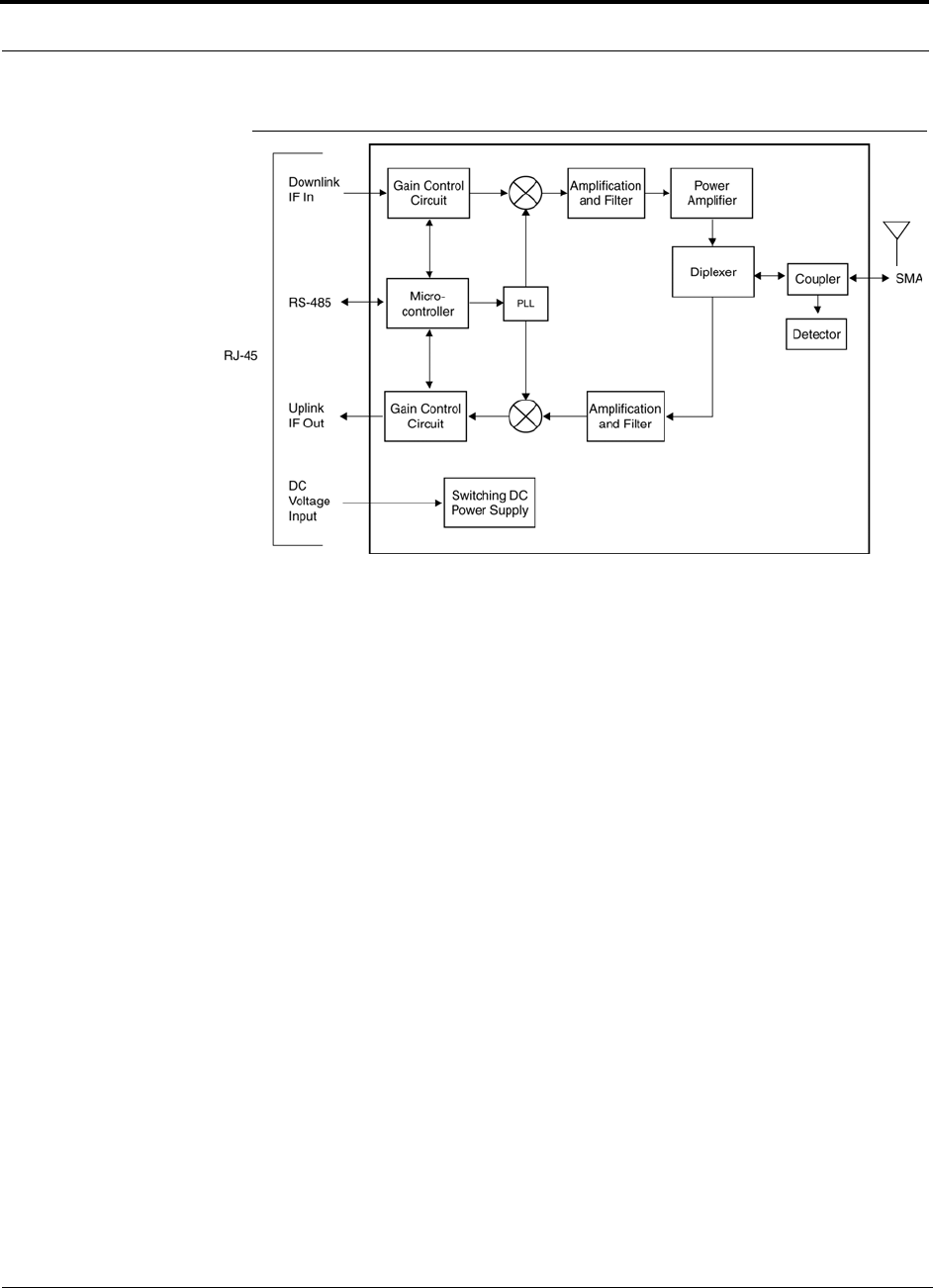
5-2 InterReach Unison Installation, Operation, and Reference Manual
CONFIDENTIAL D-620003-0-20 Rev M
Figure 5-2 Remote Access Unit Block Diagram
Antenna

Help Hot Line (U.S. only): 1-800-530-9960 5-3
D-620003-0-20 Rev M CONFIDENTIAL
The Unison RAUs are manufactured to a specific band or set of bands. Table 5-1 lists
the Unison RAUs, the Unison Band, and the frequency band(s) they cover.
** For Japan, see separate addendum - Japan’s Specification Document.
Table 5-1 Frequency Bands covered by Unison RAUs
Unison
RAU Part Number Unison
Band
RF Passband
Downlink (MHz) Uplink (MHz)
Cellular UNS-CELL-1 Cellular 869–894 824–849
DCS UNS-DCS-1 DCS1 1805–1842.5 1710–1747.5
DCS2 1842.5–1880 1747.5–1785
DCS4 1815–1850 1720–1755
GSM UNS-GSM-1 GSM 925–960 880–915
iDEN UNS-IDEN-1 iDEN 851–869 806–824
PCS UNS-PCS-2 PCS A,D,B 1930–1965 1850–1885
PCS D,B,E,F 1945–1975 1865–1895
PCS E,F,C 1965–1990 1885–1910
PCS
A4/A5/D/B/E 1935-1970 1655-1890
PCS
A5/D/B/E/F 1940-1975 1860-1895
PCS
D/B/E/F/C2 1945-1982.5 1865-1902.5
PCS
B4/B5/E/F/C 1955-1990 1875-1910
UMTS UNS-UMTS-2 UMTS 1 2110–2145 1920–1955
UMTS 2 2125–2160 1935–1970
UMTS 3 2135–2170 1945–1980
UNS-J1-UMTS
** UMTS 1-Japan 2110–2130 1920–1940
UMTS 2-Japan 2130–2150 1940–1960
UMTS 3-Japan 2150–2170 1960–1980
AWS UNS-AWS-1 AWS1 2110-2145 1710-1745
AWS2 2120-2155 1720-1755
PS 700 UNS-PS70-1 PS700 763-776 793-806
700
LTE UNS-CS75-1 700 UC 746-757 776-787

Remote Access Unit Connectors
5-4 InterReach Unison Installation, Operation, and Reference Manual
CONFIDENTIAL D-620003-0-20 Rev M
5.1 Remote Access Unit Connectors
5.1.1 SMA Connector
The RAU has one female SMA connector. The connector is a duplexed RF input/out-
put port that connects to a standard passive antenna using coaxial cable.
5.1.2 RJ-45 Connector
The RAU has one RJ-45 connector that connects it to an Expansion Hub using
Cat-5/5E/6 ScTP cable. Use shielded RJ-45 connectors on the Cat-5/5E/6 cable.
NOTE: For system performance, use only Cat-5/5E/6 ScTP cable with
shielded RJ-45 connectors.
5.2 LED Indicators
Upon power up, the RAU goes through a two-second test to check the LED lamps.
During this time, the LEDs blink green/green red/red. This lets you visually verify
that the LED lamps and the firmware are functioning properly.
NOTE: Refer to Section 9 for troubleshooting using the LEDs.
Status LEDs
The RAU status LEDs can be in one of the states shown in Table 5-2. These LEDs
can be:
off
steady green
steady red
There is no off state when the unit’s power is on.
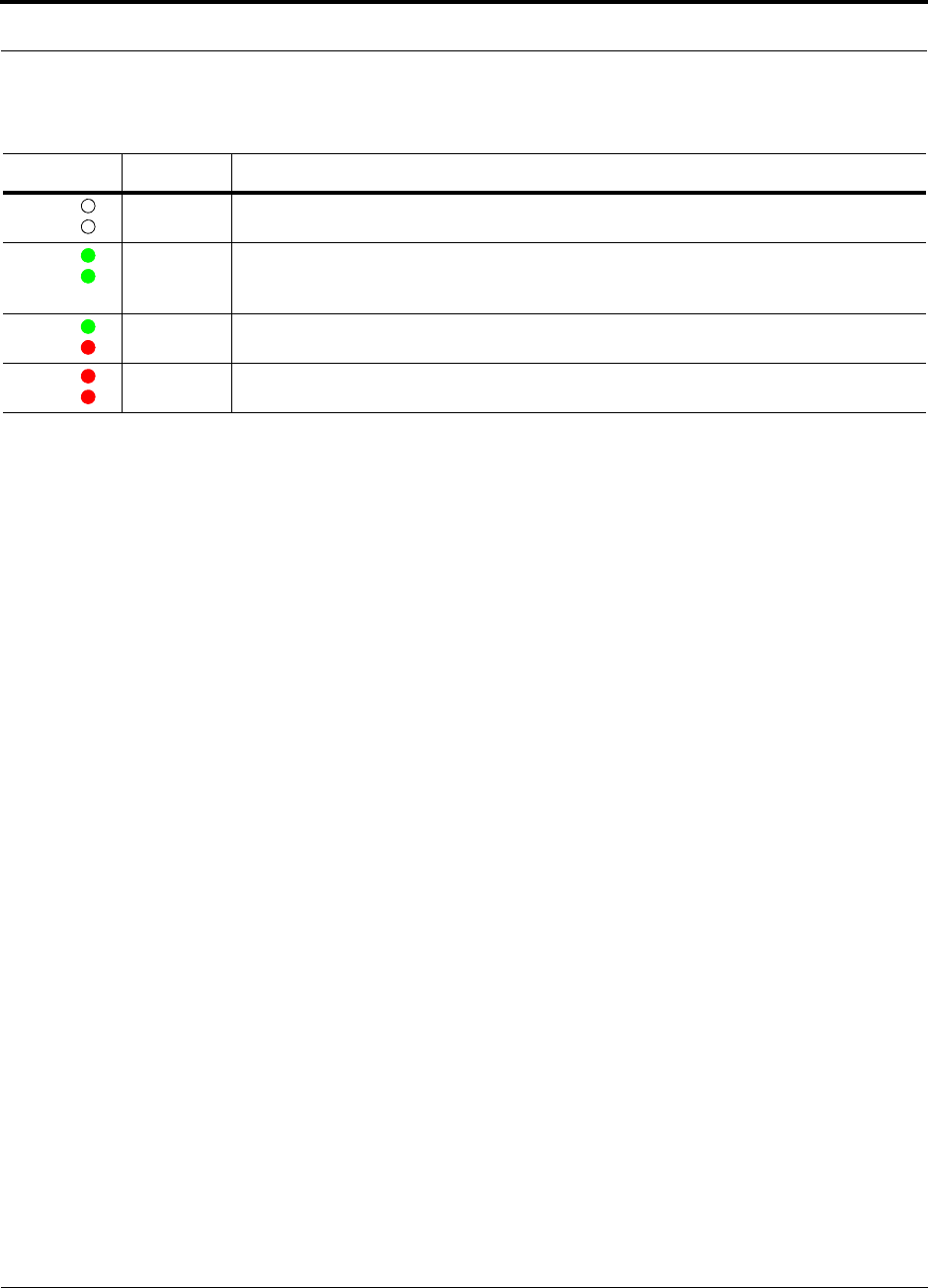
Help Hot Line (U.S. only): 1-800-530-9960 5-5
D-620003-0-20 Rev M CONFIDENTIAL
LED Indicators
Table 5-2 Remote Access Unit LED States
LED State Indicates
Off
Off • The RAU is not receiving DC power.
Green
Green • The RAU is powered and is not indicating a fault condition. Communication with the
Expansion Hub is normal; but the system test may need to be performed or a warning con-
dition could exist (use AdminManager to determine).
Green
Red • The RAU is indicating a fault or lockout condition, but communication with the Expansion
Hub is normal.
Red
Red • The RAU is reporting a fault or lockout condition, and it is not able to communicate with
the Expansion Hub.
LINK
ALARM
LINK
ALARM
LINK
ALARM
LINK
ALARM

Faults, Warnings, and Status Messages
5-6 InterReach Unison Installation, Operation, and Reference Manual
CONFIDENTIAL D-620003-0-20 Rev M
5.3 Faults, Warnings, and Status Messages
An event is classified as a fault, warning, or status message.
• Faults are service impacting.
• Warnings indicate a possible service impact.
• Status messages are generally not service impacting.
NOTE: You can select the type of events AdminManager displays. Refer to
Section 3.4.2, “View Preference,” on page 3-10.
Both fault and warning conditions are reported to the Expansion Hub where they are
stored until the Main Hub queries the system status. Only faults are indicated by
LEDs.
For more information, refer to:
• page 9-15 for RAU faults.
• page 9-21 for RAU warnings.
• page 9-26 for RAU status messages.
5.4 Remote Access Unit Specifications
Table 5-3 Remote Access Unit Specifications
Specification** Description
Dimensions (H × W × D) 44 mm × 305 mm × 158 mm (1.7 in. × 12 in. × 6.2 in.)
Weight < 1 kg (< 2 lb)
Operating Temperature** –25° to +45°C (–13° to +113°F)
Non-operating Temperature** –25° to +85°C (–13° to +185°F)
Operating Humidity, non-condensing 5% to 95%
RF Connectors 1 shielded RJ-45, female (Cat-5/6)a
1 SMA, male (coaxial)
a. For system performance, it is important that you use only Cat-5/5E/6 ScTP cable with shielded RJ-45 connectors.
** For Japan, see separate addendum - Japan Specification Document.
LED Alarm and Status Indicators Unit Status (1 pair): • Link • Alarm
Maximum Heat Dissipation (W) 12.5 typical, 16 max (from Expansion Hub)
MTBF 282,207 hours
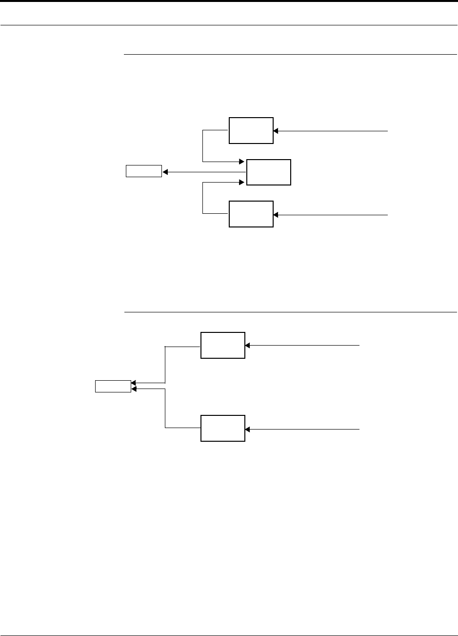
Help Hot Line (U.S. only): 1-800-530-9960 5-7
D-620003-0-20 Rev M CONFIDENTIAL
RAUs in a Dual Band System
5.5 RAUs in a Dual Band System
A Dual Band Diplexer can be used to connect two RAUs, one that is below 1 GHz
and one that is above 1 GHz, for output to a single passive antenna.
Refer to the Dual Band Diplexer specifications ADC PN: 8000-54) for technical
information.
An alternative to a diplexer is use dual-port, dual-band antennas shown in Table 5-3.
Figure 5-3 Dual-Port Antenna Configuration
Unison
RAU
Unison
RAU
Dual Band
Diplexer
Cat-5/6 from Expansion Hub
Cat-5/6 from Expansion Hub
Antenna
3 ft. coaxial cable
3 ft. coaxial cable
Unison
RAU
Unison
RAU
Cat-5/5E/6 from Expansion Hub
Cat-5/5E/6 from Expansion Hub
Antenna
3 ft. coaxial cable
3 ft. coaxial cable

RAUs in a Dual Band System
5-8 InterReach Unison Installation, Operation, and Reference Manual
CONFIDENTIAL D-620003-0-20 Rev M

InterReach Unison Installation, Operation, and Reference Manual 6-1
D-620003-0-20 Rev M CONFIDENTIAL
SECTION 6 Designing a Unison Solution
Designing a Unison solution is a matter of determining coverage and capacity needs.
This requires the following steps:
1. Determine the wireless service provider’s requirements.
This information is usually determined by the service provider:
• Frequency (that is, 850 MHz)
• Band (that is, “A” band in the Cellular spectrum)
• Protocol (that is, TDMA, CDMA, GSM, iDEN)
• Peak capacity requirement (this, and whether or not the building is split into
sectors, determines the number of carriers that the system will have to transmit)
• Design goal (RSSI, received signal strength at the wireless handset, that
is, –85 dBm)
The design goal is always a stronger signal than the cell phone needs. It
includes inherent factors which affect performance (refer to Section 6.4.1 on
page 6-26).
• RF source (base station or BDA), type of equipment if possible
2. Determine the power per carrier and input power from the base station or
BDA into the Main Hub: refer to Section 6.1, “Maximum Output Power Per
Carrier at RAU,” on page 6-3.
The maximum power per carrier is a function of the number of RF carriers, the
carrier headroom requirement, signal quality issues, regulatory emissions require-
ments, and Unison’s RF performance. Typically, the power per carrier decreases
as the number of carriers increases.
3. Determine the in-building environment: refer to Section 6.2, “Estimating RF
Coverage,” on page 6-13.
• Determine which areas of the building require coverage (entire building, public
areas, parking levels, and so on.)
• Obtain floor plans to determine floor space of building and the wall layout of
the proposed areas to be covered. Floor plans are also useful when selecting
antenna locations.

6-2 InterReach Unison Installation, Operation, and Reference Manual
CONFIDENTIAL D-620003-0-20 Rev M
• If possible, determine the building’s construction materials (sheetrock, metal,
concrete, and so on.)
• Determine type of environment
– Open layout (for example, a convention center)
– Dense, close walls (for example, a hospital)
– Mixed use (for example, an office building with hard wall offices and cubi-
cles)
4. Develop an RF link budget: refer to Section 6.4, “Link Budget Analysis,” on
page 6-26.
Knowing the power per carrier, you can calculate an RF link budget. This is used
to predict how much propagation loss can be allowed in the system, while still
providing satisfactory performance throughout the area being covered. The link
budget is a methodical way to derive a “design goal”. If the design goal is pro-
vided in advance, the link budget is: allowable RF loss = maximum power per
carrier – design goal.
5. Determine the appropriate estimated path loss slope that corresponds to the
type of building and its layout, and estimate the coverage distance for each
RAU: refer to Section 6.2, “Estimating RF Coverage,” on page 6-13.
The path loss slope (PLS), which gives a value to the RF propagation characteris-
tics within the building, is used to convert the RF link budget into an estimate of
the coverage distance per antenna. This helps establish the Unison equipment
quantities needed. The actual path loss slope that corresponds to the specific RF
environment inside the building can also be determined empirically by perform-
ing an RF site-survey of the building. This involves transmitting a calibrated tone
for a fixed antenna and making measurements with a mobile antenna throughout
the area surrounding the transmitter.
6. Determine the items required to connect to the base station: refer to
Section 6.6, “Connecting a Main Hub to a Base Station,” on page 6-39.
Once you know the quantities of Unison equipment you will use, you can deter-
mine the accessories (combiners/dividers, surge suppressors, repeaters, attenua-
tors, circulators, and so on.) required to connect the system to the base station.
The individual elements that must be considered in designing a Unison solution are
explained in the following sections.
NOTE: Access the ADC customer portal at adc.com for on-line dimension-
ing and design tools.
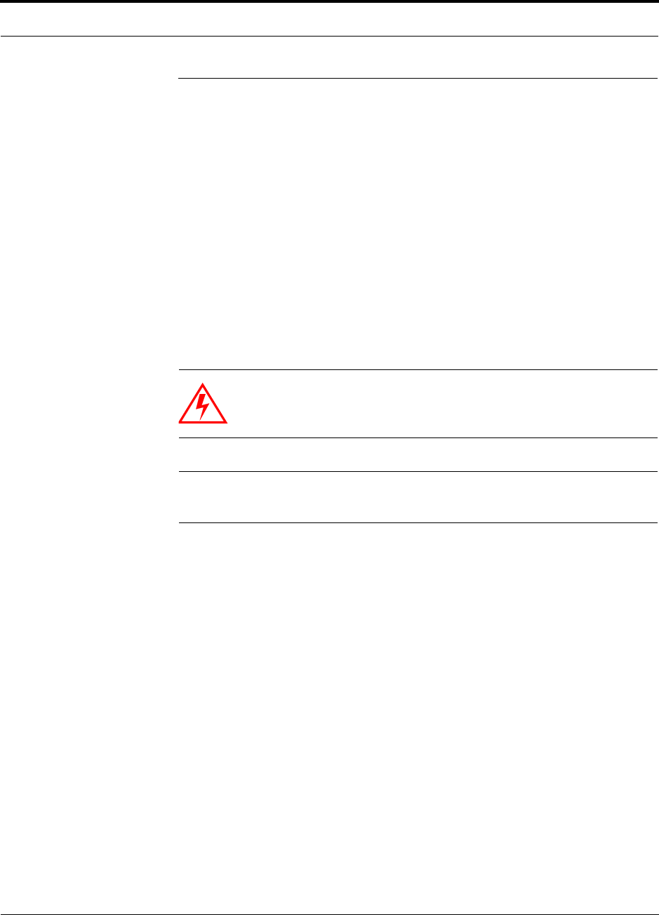
Help Hot Line (U.S. only): 1-800-530-9960 6-3
D-620003-0-20 Rev M CONFIDENTIAL
Maximum Output Power Per Carrier at RAU
6.1 Maximum Output Power Per Carrier at RAU
The following tables show the recommended maximum power per carrier out of the
RAU SMA connector for different frequencies, formats, and numbers of carriers.
These limits are dictated by RF signal quality and regulatory emissions issues. The
maximum input power to the Main Hub is determined by subtracting the system gain
from the maximum output power of the RAU. System gain is software selectable
from 0 dB to 15 dB in 1 dB steps. Additionally, both the uplink and downlink of each
RAU gain can be reduced by 10 dB.
When you connect a Main Hub to a base station or repeater, the RF power per carrier
usually needs to be attenuated in order to avoid exceeding Unison’s maximum output
power recommendations.
Refer to Section 6.7, “Designing for a Neutral Host System,” on page 6-46 when
combining frequencies or protocols on a single Main Hub.
WARNING: Exceeding the maximum input power could cause per-
manent damage to the Main Hub. Do not exceed the maximum com-
posite input power of 1W (+30 dBm) to the Main Hub at any time.
NOTE: These specifications are for downlink power at the RAU output (excluding
antenna).
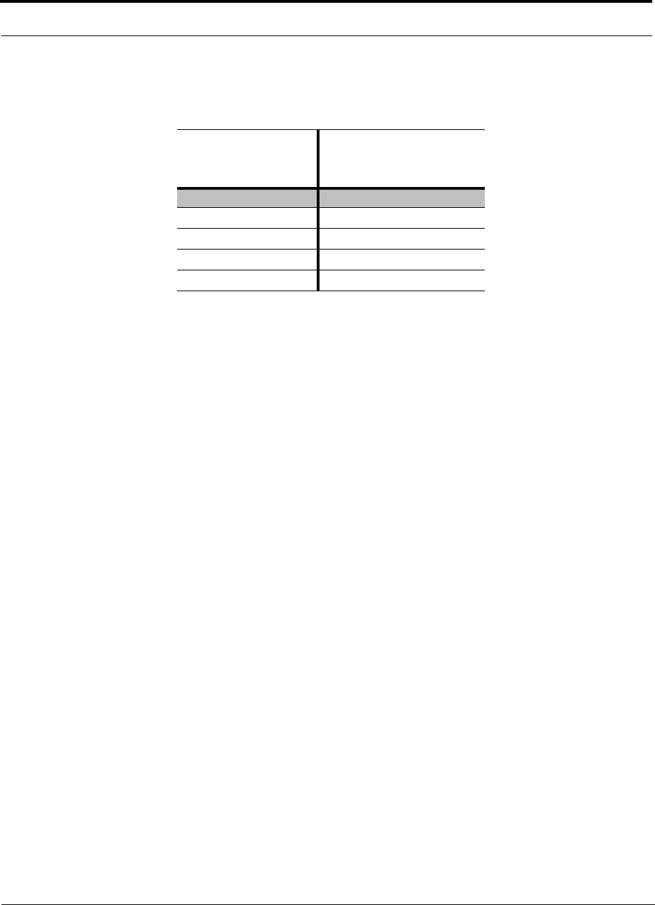
Maximum Output Power Per Carrier at RAU
6-4 InterReach Unison Installation, Operation, and Reference Manual
CONFIDENTIAL D-620003-0-20 Rev M
6.1.1 700 MHz LTE
Table 6-1 700 MHz Power per Carrier
No. of Carriers
Power per Carrier (dBm)
LTE
115.0
2
11.0
3
8.0
4
6.5
5
5.0
These PPC numbers assume 2 km of SMF or 1 km of MMF.
Note: Operation at or above these output power levels may prevent Unison from meet-
ing RF performance specifications or FCC Part 15 and EN55022 emissions require-
ments. Refer to the Unison Installation, Operation, and Reference manual for system
design information.

Help Hot Line (U.S. only): 1-800-530-9960 6-5
D-620003-0-20 Rev M CONFIDENTIAL
Maximum Output Power Per Carrier at RAU
6.1.2 800 MHz Cellular
Table 6-2 Cellular Power per Carrier
No. of
Carriers
Power per Carrier (dBm)
AMPS
2 km SMF/
1 km MMF
TDMA
2 km SMF/
1 km MMF GSM
2 km SMF GSM
1 km MMF EDGE
2 km SMF EDGE
1 km MMF
CDMA
2 km SMF/
1 km MMF
127.0 24.0 27.0 27.0 24.0 24.0 17.0
2
21.0 19.0 14.5 12.5 14.5 12.5 14.0
3
17.5 16.0 12.5 10.5 12.5 10.5 12.0
4
14.5 14.0 11.5 9.5 11.5 9.5 11.0
5
13.0 12.5 10.5 8.5 10.5 8.5 10.0
6
11.5 11.5 9.5 7.5 9.5 7.5 9.0
7
10.5 10.5 9.0 7.0 9.0 7.0 8.5
8
9.5 9.5 8.5 6.5 8.5 6.5 8.0
9
9.0 9.0 8.5 6.5 8.5 6.5
10
8.0 8.5 8.0 6.0 8.0 6.0
11
8.0 8.0 7.5 5.5 7.5 5.5
12
7.5 7.5 7.5 5.5 7.0 5.5
13
7.0 7.5 7.0 5.0 7.0 5.0
14
6.5 7.0 7.0 5.0 6.5 5.0
15
6.5 6.5 6.5 4.5 6.0 4.5
16
6.0 6.5 6.5 4.5 6.0 4.5
20
5.0 5.5 5.5 3.5 5.0 3.5
30
3.0 3.5 4.0 2.0 3.0 2.5
Note: Operation at or above these output power levels may prevent Unison from meeting RF performance specifications or FCC Part 15 and EN55022 emis-
sions requirements. Refer to the Unison Installation, Operation, and Reference manual for system design information.

Maximum Output Power Per Carrier at RAU
6-6 InterReach Unison Installation, Operation, and Reference Manual
CONFIDENTIAL D-620003-0-20 Rev M
6.1.3 800 MHz iDEN/SMR
Table 6-3 iDEN/SMR Power per Carrier
No. of
Carriers
Power per Carrier (dBm)
iDEN
2 km SMF/
1 km MMF
Analog FM
2 km SMF/
1 km MMF
CQPSK
2 km SMF/
1 km MMF
C4FM
2 km SMF/
1 km MMF
Motient Data
TAC
2 km SMF/
1 km MMF
110.0 10.0 10.0 10.0 10.0
2
10.0 10.0 10.0 10.0 10.0
3
10.0 10.0 10.0 10.0 10.0
4
10.0 10.0 10.0 10.0 10.0
5
9.0 10.0 10.0 10.0
6
8.0 10.0 9.5 10.0
7
7.0 9.5 9.0 9.0
8
6.5 8.5 8.0 8.5
9
6.0 8.0 7.5 7.5
10
5.5 7.0 7.0 7.0
Note: Operation at or above these output power levels may prevent Unison from meeting RF performance specifications or FCC Part 15 and EN55022 emis-
sions requirements. Refer to the Unison Installation, Operation, and Reference manual for system design information.
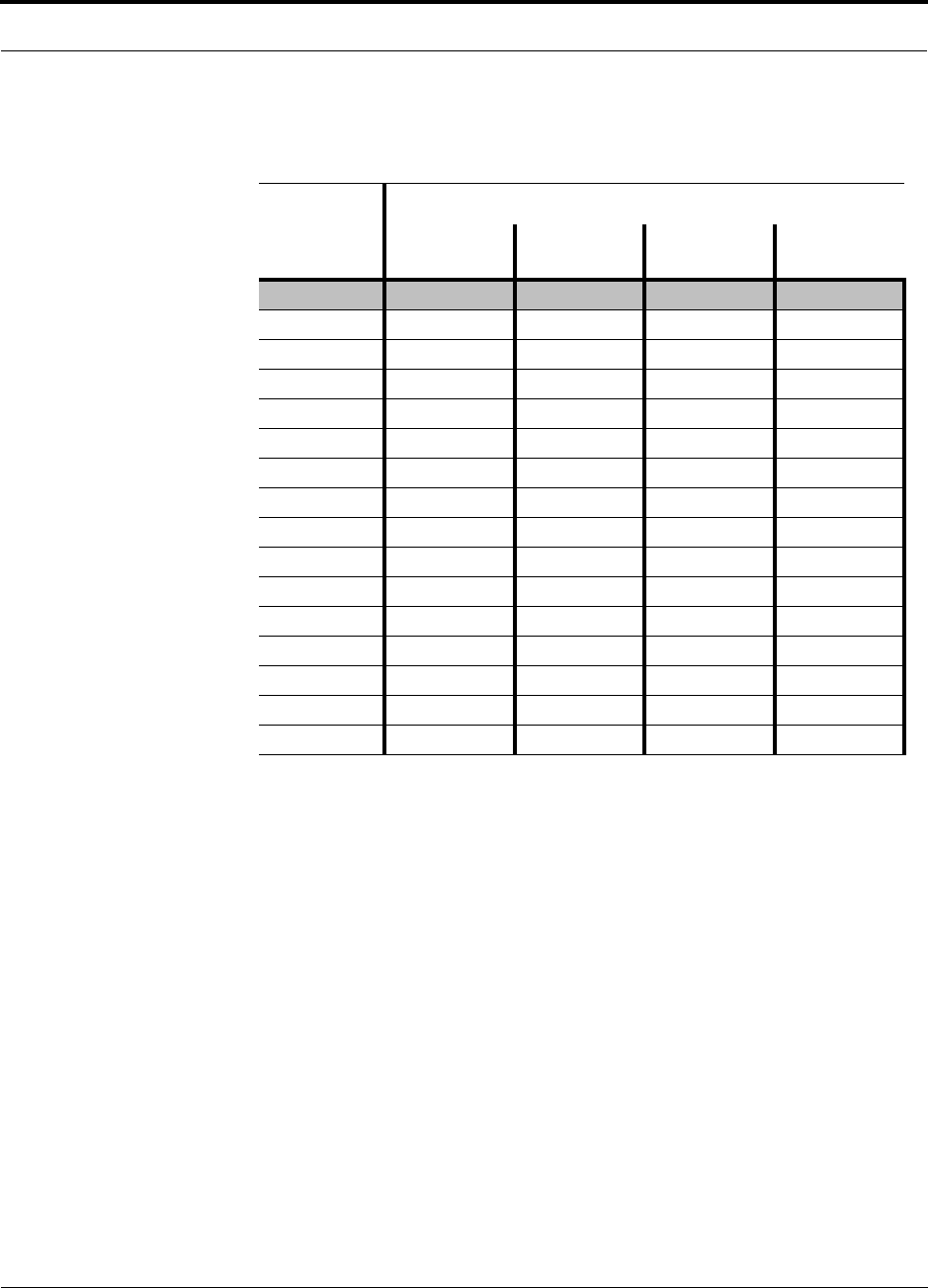
Help Hot Line (U.S. only): 1-800-530-9960 6-7
D-620003-0-20 Rev M CONFIDENTIAL
Maximum Output Power Per Carrier at RAU
6.1.4 900 MHz GSM and EDGE
Table 6-4 GSM and EDGE Power per Carrier
No. of
Carriers
Power per Carrier (dBm)
GSM
2 km SMF GSM
1 km MMF EDGE
2 km SMF EDGE
1 km MMF
116.0 16.0 16.0 16.0
2 13.0 12.0 13.0 12.0
3 11.0 10.0 11.0 10.0
4 10.0 9.0 10.0 9.0
5 9.0 8.0 9.0 8.0
6 8.0 7.0 8.0 7.0
7 7.5 6.5 7.5 6.5
8 7.0 6.0 7.0 6.0
9 6.5 5.5 6.5 5.5
10 6.0 5.5 6.0 5.5
11 5.5 5.0 5.5 5.0
12 5.0 4.5 5.0 4.5
13 5.0 4.5 5.0 4.5
14 4.5 4.0 4.5 4.0
15 4.0 4.0 4.0 4.0
16 4.0 3.5 4.0 3.5
Note: Operation at or above these output power levels may prevent Unison from meeting RF performance specifications or FCC Part 15
and EN55022 emissions requirements. Refer to the Unison Installation, Operation, and Reference manual for system design informa-
tion.

Maximum Output Power Per Carrier at RAU
6-8 InterReach Unison Installation, Operation, and Reference Manual
CONFIDENTIAL D-620003-0-20 Rev M
6.1.5 1800 MHz DCS
Table 6-5 DCS Power per Carrier
No. of
Carriers
Power per Carrier (dBm)
GSM
2 km SMF GSM
1 km MMF EDGE
2 km SMF EDGE
1 km MMF CDMA
2 km SMF/1 km MMF
117.5 17.5 17.5 17.5 16.0
2 14.5 14.0 14.5 14.0 13.0
3 12.5 12.0 12.5 12.0 11.0
4 11.5 11.0 11.5 11.0 10.0
5 10.5 10.0 10.5 10.0 9.0
6 9.5 9.0 9.5 9.0 8.0
7 9.0 8.5 9.0 8.5 7.5
8 8.5 8.0 8.0 8.0 7.0
9 8.0 7.5 7.5 7.5 6.5
10 7.5 7.5 7.0 7.0 6.0
11 7.0 7.0 6.5 6.5 5.5
12 6.5 6.5 6.0 6.0 5.0
13 6.5 6.5 6.0 6.0 5.0
14 6.0 6.0 5.5 5.5 4.5
15 5.5 5.5 5.0 5.0 4.0
16 5.5 5.5 5.0 5.0 4.0
Note: Operation at or above these output power levels may prevent Unison from meeting RF performance specifications or FCC Part 15 and
EN55022 emissions requirements. Refer to the Unison Installation, Operation, and Reference manual for system design information.

Help Hot Line (U.S. only): 1-800-530-9960 6-9
D-620003-0-20 Rev M CONFIDENTIAL
Maximum Output Power Per Carrier at RAU
6.1.6 1900 MHz PCS
Table 6-6 PCS Power per Carrier
No. of
Carriers
Power per Carrier (dBm)
TDMA
2 km SMF/1 km MMF GSM
2 km SMF GSM
1 km MMF EDGE
2 km SMF EDGE
1 km MMF CDMA
2 km SMF/1 km MMF
123.0 26.0 26.0 23.0 23.0 16.0
2
18.0 15.5 14.0 15.5 14.0 13.0
3
15.0 13.5 12.0 13.5 12.0 11.0
4
13.0 12.0 11.0 12.0 11.0 10.0
5
11.5 11.0 10.0 10.5 10.0 9.0
6
10.5 10.5 9.0 9.5 9.0 8.0
7
9.5 10.0 8.5 9.0 8.5 7.5
8
8.5 9.0 8.0 8.0 8.0 7.0
9
8.0 8.5 7.5 7.5 7.5
10
7.5 8.0 7.5 7.0 7.0
11
7.0 7.5 7.0 6.5 6.5
12
6.5 7.0 6.5 6.0 6.0
13
6.5 6.5 6.5 6.0 6.0
14
6.0 6.5 6.0 5.5 5.5
15
5.5 6.0 6.0 5.0 5.0
16
5.5 5.5 5.5 5.0 5.0
20
4.5 4.5 4.5 4.0 4.0
30
2.5 3.0 3.0 2.0 2.0
Note: Operation at or above these output power levels may prevent Unison from meeting RF performance specifications or FCC Part 15 and EN55022
emissions requirements. Refer to the Unison Installation, Operation, and Reference manual for system design information.

Maximum Output Power Per Carrier at RAU
6-10 InterReach Unison Installation, Operation, and Reference Manual
CONFIDENTIAL D-620003-0-20 Rev M
6.1.7 2.1 GHz UMTS
6.1.8 1.7/2.1 GHz AWS
Table 6-7 UMTS Power per Carrier**
No. of
Carriers
Power per Carrier (dBm)
WCDMA
2 km SMF/1 km MMF
1
15.0
211.0
38.0
46.5
55.0
64.0
73.0
These PPC numbers assume 2 km of SMF or 1 km of MMF.
Note: measurements taken with no baseband clipping.
Note: Operation at or above these output power levels may prevent Unison from meeting RF performance specifications or
FCC Part 15 and EN55022 emissions requirements. Refer to the Unison Installation, Operation, and Reference manual for
system design information.
** For Japan, refer to separate addendum - Japan Specification Document.
Table 6-8 AWS Power per Carrier
No. of
Carriers
Power per Carrier (dBm)
WCDMA
2 km SMF/1 km MMF
1
15.0
211.0
38.0
46.5
55.0
64.0
73.0
These PPC numbers assume 2 km of SMF or 1 km of MMF.
Note: measurements taken with no baseband clipping.
Note: Operation at or above these output power levels may prevent Unison from meeting RF performance specifications or
FCC Part 15 and EN55022 emissions requirements. Refer to the Unison Installation, Operation, and Reference manual for
system design information.
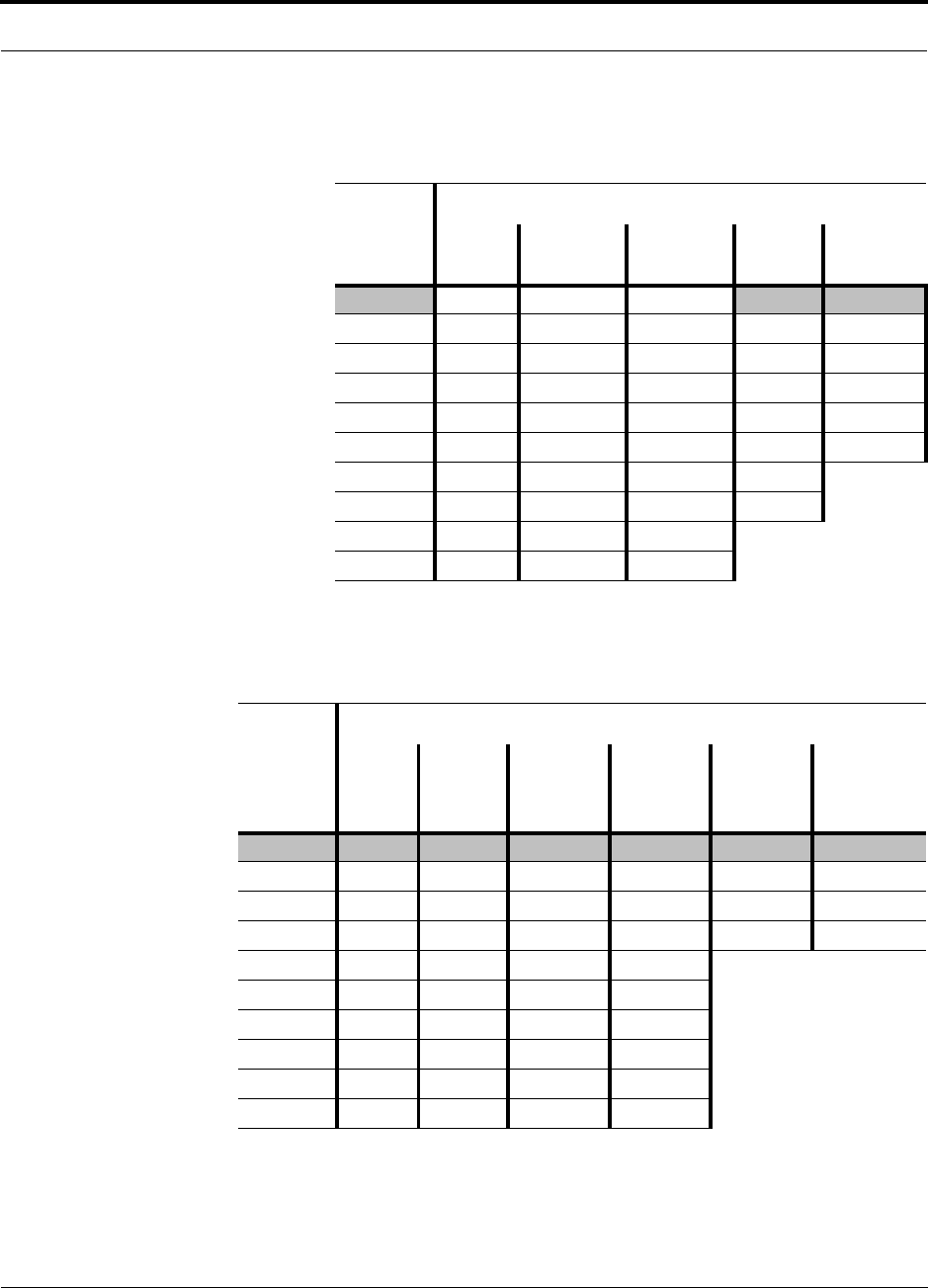
Help Hot Line (U.S. only): 1-800-530-9960 6-11
D-620003-0-20 Rev M CONFIDENTIAL
Maximum Output Power Per Carrier at RAU
6.1.9 700 MHz Public Safety
Table 6-9 Public Safety 700 MHz Power per Carrier
No. of
Carriers
Power per Carrier (dBm)
iDEN APCO25
CQPSK APCO25
C4FM CDMA
2000 WCDMA
1 10.0 10.0 10.0 16.0 15.0
2
10.0 10.0 10.0 13.0 11.0
3
10.0 10.0 10.0 11.0 8.0
4
10.0 10.0 10.0 10.0 6.5
5
9.0 10.0 10.0 9.0 5.0
6
8.0 9.5 10.0 8.0
7
7.0 9.0 9.0 7.5
8
6.5 8.0 8.5 7.0
9
6.0 7.5 7.5
10
5.5 7.0 7.0
Note: Operation at or above these output power levels may prevent Unison from meeting RF performance specifications
or FCC Part 15 and EN55022 emissions requirements. Refer to the Unison Installation, Operation, and Reference man-
ual for system design information.
Table 6-10 900 MHz Paging/SMR/iDEN
No. of
Carriers
Power per Carrier (dBm)
iDEN
2 km SMF
1 km MMF
Analog
FM
2 km SMF
1 km MMF
CQPSK
2 km SMF
1 km MMF
C4FM
2 km SMF
1 km MMF
Mobitex
2 km SMF
1 km MMF
POCSAG/
REFLEX
2 km SMF
1 km MMF
117.5 26.0 22.0 26.0 26.0 26.0
2
14.0 19.5 17.0 19.5 19.5 19.5
3
11.5 16.5 14.5 16.0 16.0 16.0
4
10.0 13.5 12.5 13.5 13.5 13.5
5
9.0 12.0 11.0 11.5
6
8.0 10.5 9.5 10.0
7
7.0 9.5 9.0 9.0
8
6.5 8.5 8.0 8.5
9
6.0 8.0 7.5 7.5
10
5.5 7.0 7.0 7.0
Note: Operation at or above the output power levels may prevent Unison from meeting RF performance specifications or FCC Part 15 and
EN55022 emissions requirements. Refer to the Unison Installation, Operation, and Reference manual for system design information.
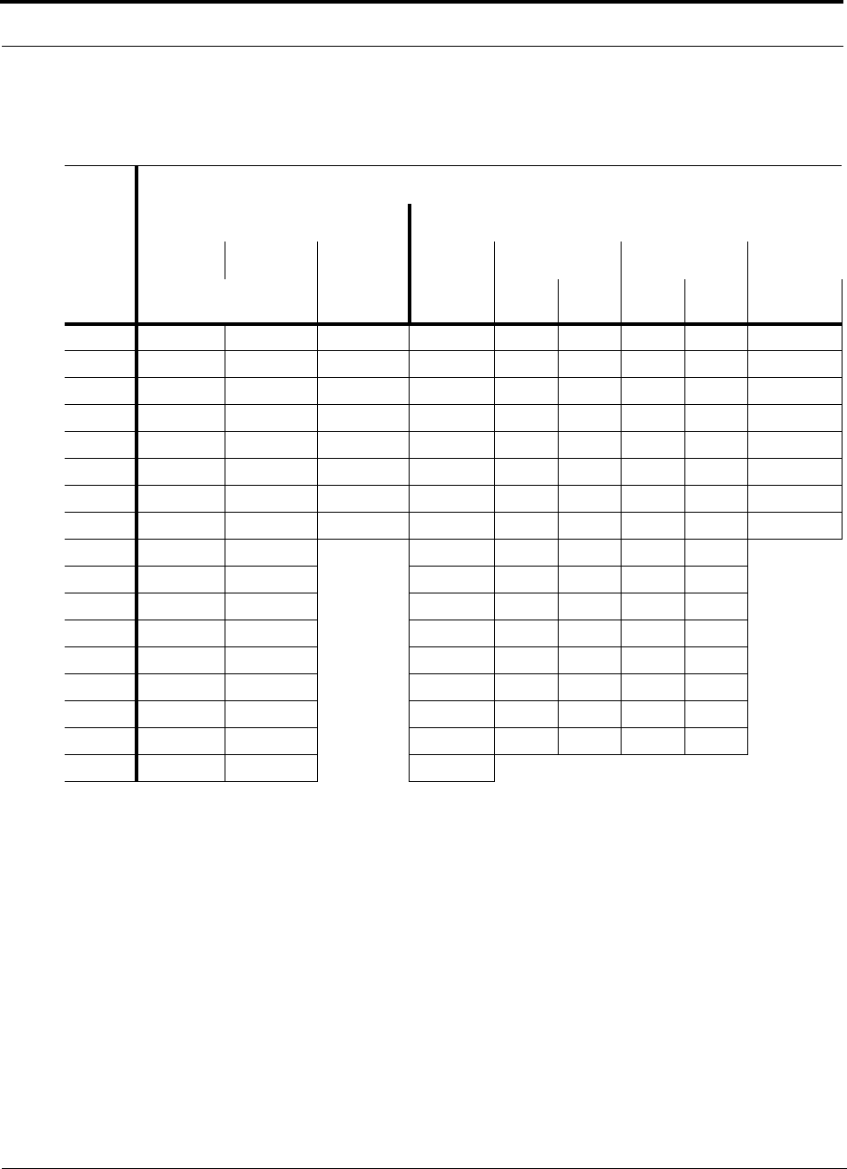
Maximum Output Power Per Carrier at RAU
6-12 InterReach Unison Installation, Operation, and Reference Manual
CONFIDENTIAL D-620003-0-20 Rev M
Allowing for Future Capacity Growth
Sometimes a Unison deployment is initially used to enhance coverage. Later, that
same system may also need to provide increased capacity. Thus, the initial deploy-
ment might only transmit two carriers but need to transmit four carriers later. There
are two options for dealing with this scenario:
1. Design the initial coverage with a maximum power per carrier for four carriers.
2. Design the initial coverage for two carriers but leave RAU ports on the Expansion
Hubs unused. These ports can be used later if coverage holes are discovered once
the power per carrier is lowered to accommodate the two additional carriers.
Table 6-11 800 MHz Cellular/1900 MHz PCS Power per Carrier
No. of
Carriers
Recommended Maximum Output Power per Carrier at RAU (dBm)
800 MHz Cellular 1900 MHz PCS
TDMA AMPS CDMA TDMA GSM EDGE CDMA
2 km SMF/
1 km MMF 2 km SMF/
1 km MMF 2 km SMF/
1 km MMF 2 km
SMF 2 km
SMF 1 km
MMF 2 km
SMF 1 km
MMF 2 km SMF/
1 km MMF
1 23.0 26.0 16.0 21.5 24.5 24.5 21.5 21.5 14.5
2 18.0 20.0 13.0 16.5 14.0 12.5 14.0 12.5 11.5
3 15.0 16.5 11.0 13.5 12.0 10.5 12.0 10.5 9.5
4 13.0 13.5 10.0 11.5 10.5 9.5 10.5 9.5 8.5
5 11.5 12.0 9.0 10.0 9.5 8.5 9.0 8.5 7.5
6 10.5 10.5 8.0 9.0 9.0 7.5 8.0 7.5 6.5
7 9.5 9.5 7.5 8.0 8.5 7.0 7.5 7.0 6.0
8 8.5 8.5 7.0 7.0 7.5 6.5 6.5 6.5 5.5
9 8.0 8.0 6.5 7.0 6.0 6.0 6.0
10 7.5 7.0 6.0 6.5 6.0 5.5 5.5
11 7.0 7.0 5.5 6.0 5.5 5.0 5.0
12 6.5 6.5 N/A 5.0 5.5 5.0 4.5 4.5
13 6.5 6.0 5.0 5.0 5.0 4.5 4.5
14 6.0 5.5 4.5 5.0 4.5 4.0 4.0
15 5.5 5.5 4.0 4.5 4.5 3.5 3.5
16 5.5 5.0 4.0 4.0 4.0 3.5 3.5
20 4.5 4.0 3.0
Note: Operation at or above these output power levels may prevent Unison from meeting RF performance specifications or FCC Part 15 and EN55022 emissions requirements.
Refer to the Unison Installation, Operation, and Reference manual for system design information.
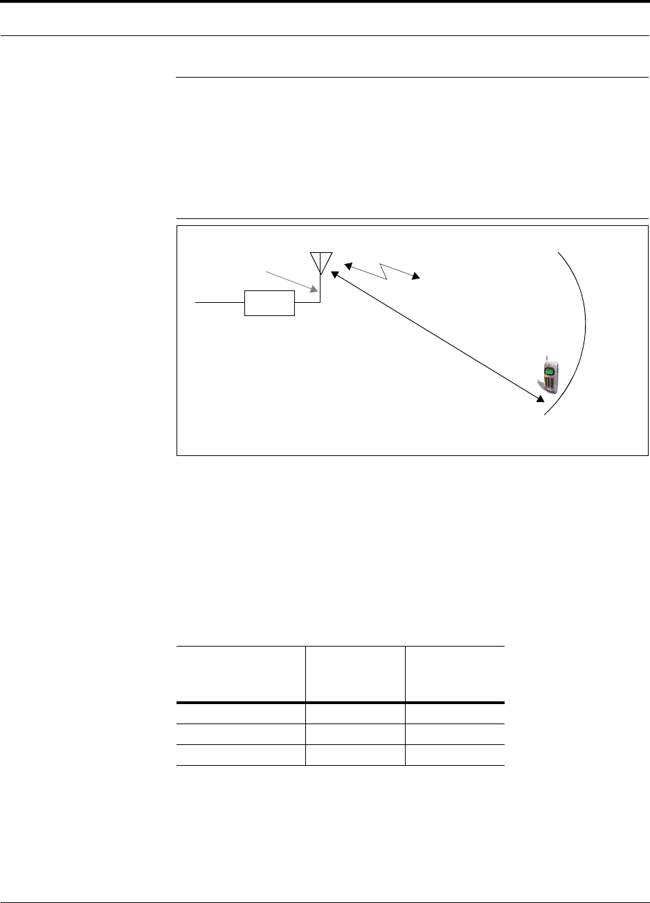
Help Hot Line (U.S. only): 1-800-530-9960 6-13
D-620003-0-20 Rev M CONFIDENTIAL
Estimating RF Coverage
6.2 Estimating RF Coverage
The maximum power per carrier (based on the number and type of RF carriers that
are being transmitted) and the minimum acceptable received power at the wireless
device (i.e., RSSI, the design goal) establish the RF link budget, and consequently the
maximum acceptable path loss between the antenna and the wireless device.
Figure 6-1 Determining Path Loss between the Antenna and the Wireless Device
(P - Lcoax + G) – RSSI = PL (1)
The path loss (PL) is the loss in decibels (dB) between the antenna and the wireless
device. The distance, d, from the antenna corresponding to this path loss can be calcu-
lated using the path loss equations in Section 6.2.1 and in Section 6.2.2.
Coaxial cable is used to connect the RAU to an antenna. The following table lists
coaxial cable loss for various cable lengths.
Table 6-12 Coaxial Cable Losses (Lcoax)
Length of Cable
(.195 in. diameter)
Loss at
800 MHz
(dB)
Loss at
1900 MHz
(dB)
0.9 m (3 ft) 0.6 0.8
1.8 m (6 ft) 1.0 1.5
3.0 m (10 ft) 1.5 2.3
RAU
P = power per Distance = d
Antenna Gain = G
RSSI = power at the
wireless device
carrier from the RAU
Coax cable loss = Lcoax

Estimating RF Coverage
6-14 InterReach Unison Installation, Operation, and Reference Manual
CONFIDENTIAL D-620003-0-20 Rev M
6.2.1 Path Loss Equation
Indoor path loss obeys the distance power law1 in equation (2):
PL = 20log(4πd0f/c) + PLSlog(d/d0) + Χs(2)
where:
• PL is the path loss at a distance, d, from the antenna (the distance between the
antenna connected to the RAU and the point where the RF signal decreases to
the minimum acceptable level at the wireless device).
• d is the distance expressed in meters.
•d
0 is usually taken as 1 meter of free-space.
• f is the operating frequency in Hertz.
• c is the speed of light in a vacuum (3.0 × 10⁸ m/sec).
• PLS is the path loss slope and depends on the building “clutter” or environ-
ment.
•Χs is a normal random variable that depends on partition losses inside the build-
ing, and therefore, depends on the frequency of operation.
As a reference, the following table gives estimates of signal loss for some RF barriers.1
1. Rappaport, Theodore S. Wireless Communications, Principles, and Practice. Prentice Hall PTR, 1996.
Table 6-13 Average Signal Loss of Common Building Materials
Partition Type Loss (dB) Frequency (MHz)
Metal wall 26 815
Aluminum siding 20 815
Foil insulation 4 815
Cubicle walls 1.4 900
Concrete block wall 13 1300
Concrete floor 10 1300
Sheetrock 1 to 2 1300
Light machinery 3 1300
General machinery 7 1300
Heavy machinery 11 1300
Equipment racks 7 1300
Assembly line 6 1300
Ceiling duct 5 1300
Metal stairs 5 1300

Help Hot Line (U.S. only): 1-800-530-9960 6-15
D-620003-0-20 Rev M CONFIDENTIAL
Estimating RF Coverage
6.2.2 Coverage Distance
Use equations (1) and (2), on pages 6-13 and 6-14, respectively, to estimate the dis-
tance from the antenna to where the RF signal decreases to the minimum acceptable
level at the wireless device.
Equation (2) can be simplified to:
PL(d) = 20log(4πf/c) + PLSlog(d) (3)
where PLS (path loss slope) is chosen to account for the building’s environment.
Because different frequencies penetrate partitions with different losses, the value of
PLS varies depending on the frequency.
Table 6-14 shows the estimated path loss slope (PLS) for various environments that
have different “clutter” (that is, objects that attenuate the RF signals, such as walls,
partitions, stairwells, equipment racks, and so on.)
For simplicity, Equation (3), Coverage Distance, can be used to estimate the coverage
distance of an antenna connected to an RAU, for a given path loss, frequency, and
type of in-building environment.
Table 6-14 Estimated Path Loss Slope for Different In-Building Environments
Environment Type Example PLS for
800/900 MHz PLS for 1800
/1900/2100 MHz
Open Environment with very few
RF obstructions Parking Garage, Convention Center 33.7 30.1
Moderately Open Environment
with low-to-medium amount of RF
obstructions
Warehouse, Airport, Manufacturing 35 32
Mildly Dense Environment with
medium-to-high amount of RF
obstructions
Retail, Office Space with approxi-
mately 80% cubicles and 20% hard
walled offices
36.1 33.1
Moderately Dense Environment
with medium-to-high amount of RF
obstructions
Office Space with approximately
50% cubicles and 50% hard walled
offices
37.6 34.8
Dense Environment with large
amount of RF obstructions Hospital, Office Space with approxi-
mately 20% cubicles and 80% hard
walled offices
39.4 38.1

Estimating RF Coverage
6-16 InterReach Unison Installation, Operation, and Reference Manual
CONFIDENTIAL D-620003-0-20 Rev M
Table 6-15 gives the value of the first term of Equation (3) (that is, (20log(4πf/c)) for
various frequency bands.
For reference, Tables 6-17 through 6-23 show the distance covered by an antenna for
various in-building environments. The following assumptions were made:
• Path loss Equation (3)
• 6 dBm output per carrier at the RAU output
• 3 dBi antenna gain
• RSSI = –85 dBm (typical for narrowband protocols, but not for spread-spec-
trum protocols)
Table 6-15 Frequency Bands and the Value of the first Term in Equation (3)
Band (MHz) Mid-Band
Frequency
(MHz) 20log(4πf/c)Uplink Downlink
800 MHz Cellular 824–849 869–894 859 31.1
800 MHz iDEN 806–824 851–869 837.5 30.9
900 MHz GSM 890–915 935–960 925 31.8
900 MHz EGSM 880–915 925–960 920 31.7
1800 MHz DCS 1710–1785 1805–1880 1795 37.5
1900 MHz PCS 1850–1910 1930–1990 1920 38.1
2.1 GHz UMTS 1920–1980 2110–2170 2045 38.7
1.7/2.1 GHz AWS 1710-1755 2110-2155 2132.5a
a. Due to the wide frequency spread between the Uplink and Downlink bands, the mid-band frequency
of the Downlink band was chosen for 1.7/2.1 GHz AWS.
39.0
700 MHz PS 793-806 763-776 784.5 30.3
700 MHz LTE 776-787 746-757 766.5 30.1
Table 6-16 Approximate Radiated Distance from Antenna
for 700 MHz LTE Applications
Facility
Distance from Antenna
Meters Feet
Open Environment 79 258
Moderately Open Environment 67 219
Mildly Dense Environment 59 193
Moderately Dense Environment 50 164
Dense Environment 42 137

Help Hot Line (U.S. only): 1-800-530-9960 6-17
D-620003-0-20 Rev M CONFIDENTIAL
Estimating RF Coverage
Table 6-17 Approximate Radiated Distance from Antenna
for 800 MHz Cellular Applications
Environment Type
Distance from Antenna
Meters Feet
Open Environment 73 241
Moderately Open Environment 63 205
Mildly Dense Environment 55 181
Moderately Dense Environment 47 154
Dense Environment 39 129
Table 6-18 Approximate Radiated Distance from Antenna
for 800 MHz iDEN Applications
Facility
Distance from Antenna
Meters Feet
Open Environment 75 244
Moderately Open Environment 64 208
Mildly Dense Environment 56 184
Moderately Dense Environment 48 156
Dense Environment 40 131
Table 6-19 Approximate Radiated Distance from Antenna
for 900 MHz GSM Applications
Facility
Distance from Antenna
Meters Feet
Open Environment 70 230
Moderately Open Environment 60 197
Mildly Dense Environment 53 174
Moderately Dense Environment 45 148
Dense Environment 38 125
Table 6-20 Approximate Radiated Distance from Antenna
for 900 MHz EGSM Applications
Facility
Distance from Antenna
Meters Feet
Open Environment 70 231
Moderately Open Environment 60 197

Estimating RF Coverage
6-18 InterReach Unison Installation, Operation, and Reference Manual
CONFIDENTIAL D-620003-0-20 Rev M
Mildly Dense Environment 53 174
Moderately Dense Environment 45 149
Dense Environment 38 125
Table 6-20 Approximate Radiated Distance from Antenna
for 900 MHz EGSM Applications
Facility
Distance from Antenna
Meters Feet

Help Hot Line (U.S. only): 1-800-530-9960 6-19
D-620003-0-20 Rev M CONFIDENTIAL
Estimating RF Coverage
Table 6-21 Approximate Radiated Distance from Antenna
for 1800 MHz DCS Applications
Facility
Distance from Antenna
Meters Feet
Open Environment 75 246
Moderately Open Environment 58 191
Mildly Dense Environment 50 166
Moderately Dense Environment 42 137
Dense Environment 30 100
Table 6-22 Approximate Radiated Distance from Antenna
for 1800 MHz CDMA (Korea) Applications
Facility
Distance from Antenna
Meters Feet
Open Environment 75 247
Moderately Open Environment 58 191
Mildly Dense Environment 51 167
Moderately Dense Environment 42 138
Dense Environment 30 100
Table 6-23 Approximate Radiated Distance from Antenna
for 1900 MHz PCS Applications
Facility
Distance from Antenna
Meters Feet
Open Environment 72 236
Moderately Open Environment 56 183
Mildly Dense Environment 49 160
Moderately Dense Environment 40 132
Dense Environment 29 96
Table 6-24 Approximate Radiated Distance from Antenna
for 2.1 GHz UMTS Applicationsa
Facility
Distance from Antenna
Meters Feet
Open Environment 69 226
Moderately Open Environment 54 176

Estimating RF Coverage
6-20 InterReach Unison Installation, Operation, and Reference Manual
CONFIDENTIAL D-620003-0-20 Rev M
Mildly Dense Environment 47 154
Moderately Dense Environment 39 128
Dense Environment 28 93
a. For Japan, refer to the separate addendum: Japan Specification Document.
Table 6-25 Approximate Radiated Distance from Antenna
for 1.7/2.1 GHz AWS Applications
Facility
Distance from Antenna
Meters Feet
Open Environment 67 220
Moderately Open Environment 52 172
Mildly Dense Environment 46 150
Moderately Dense Environment 38 125
Dense Environment 28 91
Table 6-26 Approximate Radiated Distance from Antenna
for 700 MHz Public Safety Applications
Facility
Distance from Antenna
Meters Feet
Open Environment 78 254
Moderately Open Environment 66 216
Mildly Dense Environment 58 190
Moderately Dense Environment 49 162
Dense Environment 41 136
Table 6-24 Approximate Radiated Distance from Antenna
for 2.1 GHz UMTS Applicationsa
Facility
Distance from Antenna
Meters Feet

Help Hot Line (U.S. only): 1-800-530-9960 6-21
D-620003-0-20 Rev M CONFIDENTIAL
Estimating RF Coverage
6.2.3 Examples of Design Estimates
Example Design Estimate for an 800 MHz TDMA Application
1. Design goals:
• Cellular (859 MHz = average of the lowest uplink and the highest downlink
frequency in 800 MHz Cellular band)
•TDMA provider
• 12 TDMA carriers in the system
• –85 dBm design goal (to 95% of the building) — the minimum received power
at the wireless device
• Base station with simplex RF connections
2. Power Per Carrier: The tables in Section 6.1, “Maximum Output Power Per
Carrier at RAU,” on page 6-3 provide maximum power per carrier information.
The 800 MHz TDMA table (on page 6-5) indicates that Unison can support 12
carriers with a recommended maximum power per carrier of 7.5 dBm. The input
power should be set to the desired output power minus the system gain.
3. Building information:
• Eight floor building with 9,290 sq. meters (100,000 sq. ft.) per floor; total
74,322 sq. meters (800,000 sq. ft.).
• Walls are sheetrock construction, suspended ceiling tiles.
• Antennas used will be omni-directional, ceiling mounted.
• Standard office environment, 50% hard wall offices and 50% cubicles.
4. Link Budget: In this example, a design goal of –85 dBm is used. Suppose 3 dBi
omni-directional antennas are used in the design. Then, the maximum RF propa-
gation loss should be no more than 95.5 dB (7.5 dBm + 3 dBi + 85 dBm) over
95% of the area being covered. It is important to note that a design goal such as
–85 dBm is usually derived taking into account multipath fading and log-normal
shadowing characteristics. Thus, this design goal will only be met “on average”
over 95% of the area being covered. At any given point, a fade may bring the sig-
nal level underneath the design goal.
Note that this method of calculating a link budget is only for the downlink path.
For information to calculate link budgets for both the downlink and uplink paths,
refer to Section 6.4 on page 6-26.
5. Path Loss Slope: For a rough estimate, Table 6-14, “Estimated Path Loss Slope for
Different In-Building Environments” on page 6-15, shows that a building with 50%
hard wall offices and 50% cubicles, at 859 MHz, has an approximate path loss slope
(PLS) of 37.6. Given the RF link budget of 95.5 dB, the distance of coverage from
each RAU will be 52 meters (170.6 ft). This corresponds to a coverage area of
8,494 sq. meters (91,425 sq. ft.) per RAU (refer to Section 6.2.1 for details on path
loss estimation). For this case we assumed a circular radiation pattern, though the
actual area covered depends upon the pattern of the antenna and the obstructions in
the facility.

Estimating RF Coverage
6-22 InterReach Unison Installation, Operation, and Reference Manual
CONFIDENTIAL D-620003-0-20 Rev M
Equipment Required: Since you know the building size, you can now estimate
the Unison equipment quantities that will be needed. Before any RF levels are
tested in the building, you can estimate that two antennas per level will be needed.
This assumes no propagation between floors. If there is propagation, you may not
need antennas on every floor.
a. 2 antennas per floor × 8 floors = 16 RAUs
b. 16 RAUs ÷ 8 (maximum 8 RAUs per Expansion Hub) = 2 Expansion Hubs
c. 2 Expansion Hubs ÷ 4 (maximum 4 Expansion Hubs per Main Hub) = 1 Main
Hub
Check that the fiber and Cat-5 cable distances are as recommended. If the dis-
tances differ, use the tables in Section 6.3, “System Gain,” on page 6-25 to deter-
mine system gains or losses. The path loss may need to be recalculated to assure
adequate signal levels in the required coverage distance.
The above estimates assume that all cable length requirements are met. If Expansion
Hubs cannot be placed so that the RAUs are within the distance requirement, addi-
tional Expansion Hubs may need to be placed closer to the required RAUs locations.
An RF Site Survey and Building Evaluation is required to accurately establish the
Unison equipment quantities required for the building. The site survey measures the
RF losses within the building to determine the actual PLS, which are used in the final
path loss formula to determine the actual requirements of the Unison system.

Help Hot Line (U.S. only): 1-800-530-9960 6-23
D-620003-0-20 Rev M CONFIDENTIAL
Estimating RF Coverage
Example Design Estimate for an 1900 MHz CDMA Application
1. Design goals:
• PCS (1920 MHz = average of the lowest uplink and the highest downlink fre-
quency in 1900 MHz PCS band)
•CDMA provider
• 8 CDMA carriers in the system
• –85 dBm design goal (to 95% of the building) — the minimum received power
at the wireless device
• Base station with simplex RF connections
2. Power Per Carrier: The tables in Section 6.1, “Maximum Output Power Per
Carrier at RAU,” on page 6-3 provide maximum power per carrier information.
The 1900 MHz CDMA table (on page 6-9) indicates that Unison can support
eight carriers with a recommended maximum power per carrier of 6.5 dBm. The
input power should be set to the desired output power minus the system gain.
3. Building information:
• 16 floor building with 9,290 sq. meters (100,000 sq. ft.) per floor; total
148,640 sq. meters (1,600,000 sq. ft.).
• Walls are sheetrock construction, suspended ceiling tiles.
• Antennas used are omni-directional, ceiling mounted.
• Standard office environment, 80% hard wall offices and 20% cubicles.
4. Link Budget: In this example, a design goal of –85 dBm is used. Suppose 3 dBi
omni-directional antennas are used in the design. Then, the maximum RF propa-
gation loss should be no more than 94.5 dB (6.5 dBm + 3 dBi + 85 dBm) over
95% of the area being covered. It is important to note that a design goal such as
–85 dBm is usually derived taking into account multipath fading and log-normal
shadowing characteristics. Thus, this design goal will only be met “on average”
over 95% of the area being covered. At any given point, a fade may bring the sig-
nal level underneath the design goal.
Note that this method of calculating a link budget is only for the downlink path.
For information to calculate link budgets for both the downlink and uplink paths,
refer to Section 6.4 on page 6-26.
5. Path Loss Slope: For a rough estimate, Table 6-14, “Estimated Path Loss Slope for
Different In-Building Environments” on page 6-15, shows that a building with 80%
hard wall offices and 20% cubicles, at 1920 MHz, has an approximate path loss
slope (PLS) of 38.1. Given the RF link budget of 94.5 dB, the distance of coverage
from each RAU will be 30.2 meters (99 ft). This corresponds to a coverage area
of 2,868 sq. meters (30,854 sq. ft.) per RAU (refer to Section 6.2.1 for details on
path loss estimation). For this case we assumed a circular radiation pattern, though
the actual area covered depends upon the pattern of the antenna and the obstructions
in the facility.

Estimating RF Coverage
6-24 InterReach Unison Installation, Operation, and Reference Manual
CONFIDENTIAL D-620003-0-20 Rev M
6. Equipment Required: Since you know the building size, you can now estimate
the Unison equipment quantities needed. Before you test any RF levels in the
building, you can estimate that four antennas per level will be needed. This
assumes no propagation between floors. If there is propagation, you may not need
antennas on every floor.
a. 4 antennas per floor × 16 floors = 64 RAUs
b. 64 RAUs ÷ 8 (maximum 8 RAUs per Expansion Hub) = 8 Expansion Hubs
c. 8 Expansion Hubs ÷ 4 (maximum 4 Expansion Hubs per Main Hub) = 2 Main
Hubs
Check that the fiber and Cat-5/5E/6 cable distances are as recommended. If the
distances differ, use the tables in Section 6.3, “System Gain,” on page 6-25 to
determine system gains or losses. The path loss may need to be recalculated to
assure adequate signal levels in the required coverage distance.
The above estimates assume that all cable length requirements are met. If Expansion
Hubs cannot be placed so that the RAUs are within the distance requirement, addi-
tional Expansion Hubs may need to be placed closer to the required RAUs locations.
An RF Site Survey and Building Evaluation is required to accurately establish the
Unison equipment quantities required for the building. The site survey measures the
RF losses within the building to determine the actual PLS, used in the final path loss
formula to determine the actual requirements of the Unison system.
** For Japan, see separate addendum - Japan Specification Document.

Help Hot Line (U.S. only): 1-800-530-9960 6-25
D-620003-0-20 Rev M CONFIDENTIAL
System Gain
6.3 System Gain
The system gain can be decreased from 15 dB to 0 dB gain in 1 dB increments and
the uplink and downlink gains of each RAU can be independently decreased by
10 dB in one step using AdminManager or OpsConsole.a
6.3.1 System Gain (Loss) Relative to ScTP Cable Length
The recommended minimum length of ScTP cable is 10 meters (33 ft) and the recom-
mended maximum length is 100 meters (328 ft). The system should not be operated
with ScTP cable that is less than 10 meters (33 ft) in length, system performance is
greatly compromised. If the ScTP cable is longer than 100 meters (328 ft), the gain of
the system decreases, as shown in Table 6-27.
Table 6-27 System Gain (Loss) Relative to ScTP Cable Length
ScTP Cable
Length
Typical change in system gain (dB)
ScTP with CAT-5
Extender Downlink Uplink
800 MHz TDMA/AMPS and CDMA; 900 MHz GSM and EGSM; and iDEN
180 m 110 m / 361 ft –1.0 –0.7
190 m 120 m / 394 ft –3.2 –2.4
200 m 130 m / 426 ft –5.3 –4.1
210 m 140 m / 459 ft –7.5 –5.8
220 m 150 m / 492 ft –9.7 –7.6
1800 MHz GSM (DCS); 1900 MHz TDMA, CDMA, and GSM
180 m 110 m / 361 ft –1.0 –0.7
190 m 120 m / 394 ft –4.0 –2.4
200 m 130 m / 426 ft –6.4 –4.1
210 m 140 m / 459 ft –8.8 –5.8
220 m 150 m / 492 ft –11.3 –7.6
2.1 GHz UMTSa; 1.7/2.1 GHz AWS
a. For Japan, refer to the separate addendum: Japan Specification Document.
180 m 110 m / 361 ft –1.0 –0.7
190 m 120 m / 394 ft –3.2 –2.4
200 m 130 m / 426 ft –5.3 –4.1
210 m 140 m / 459 ft –7.5 –5.8
220 m 150 m / 492 ft –9.7 –7.6
Link Budget Analysis
6-26 InterReach Unison Installation, Operation, and Reference Manual
CONFIDENTIAL D-620003-0-20 Rev M
6.4 Link Budget Analysis
A link budget is a methodical way to account for the gains and losses in an RF system
so that the quality of coverage can be predicted. The end result can often be stated as
a “design goal” in which the coverage is determined by the maximum distance from
each RAU before the signal strength falls beneath that goal.
One key feature of the link budget is the maximum power per carrier explained in
Section 6.1. While the maximum power per carrier is important as far as emissions
and signal quality requirements are concerned, it is critical that the maximum signal
into the Main Hub never exceed 1W (+30 dBm). Composite power levels above this
limit will cause damage to the Main Hub.
WARNING: Exceeding the maximum input power of 1W (+30 dBm)
could cause permanent damage to the Main Hub.
NOTE: Visit the ADC customer portal at adc.com for the on-line Link
Budget Tool.
6.4.1 Elements of a Link Budget for Narrowband Standards
The link budget represents a typical calculation that might be used to determine how
much path loss can be afforded in a Unison design. This link budget analyzes both the
downlink and uplink paths. For most configurations, the downlink requires lower
path loss and is therefore the limiting factor in the system design. It is for this reason
that a predetermined “design goal” for the downlink is sufficient to predict coverage
distance.
The link budget is organized in a simple manner: the transmitted power is calculated,
the airlink losses due to fading and body loss are summed, and the receiver sensitivity
(minimum level a signal can be received for acceptable call quality) is calculated. The
maximum allowable path loss (in dB) is the difference between the transmitted
power, less the airlink losses, and the receiver sensitivity. From the path loss, the
maximum coverage distance can be estimated using the path loss formula presented
in Section 6.2.1.
Table 6-28 provides link budget considerations for narrowband systems.

Help Hot Line (U.S. only): 1-800-530-9960 6-27
D-620003-0-20 Rev M CONFIDENTIAL
Link Budget Analysis
Table 6-28 Link Budget Considerations for Narrowband Systems
Consideration Description
BTS Transmit Power The power per carrier transmitted from the base station output
Attenuation between
BTS and Unison This includes all losses: cable, attenuator, splitter/combiner, and so forth.
On the downlink, attenuation must be chosen so that the maximum power per carrier going into the
Main Hub does not exceed the levels given in Section 6.1.
On the uplink, attenuation is chosen to keep the maximum uplink signal and noise level low enough
to prevent base station alarms but small enough not to cause degradation in the system sensitivity.
If the Unison noise figure minus the attenuation is at least 10 dB higher than the BTS noise figure,
the system noise figure is approximately that of Unison alone. Refer to Section 6.6 for ways to inde-
pendently set the uplink and downlink attenuations between the base station and Unison.
Antenna Gain The radiated output power includes antenna gain. For example, if you use a 3 dBi antenna at the
RAU that is transmitting 0 dBm per carrier, the effective radiated power (relative to an isotropic
radiator) is 3 dBm per carrier.
BTS Noise Figure This is the effective noise floor of the base station input (usually base station sensitivity is this effec-
tive noise floor plus a certain C/I ratio).
Unison Noise Figure This is Unison’s uplink noise figure, which varies depending on the number of Expansion Hubs and
RAUs, and the frequency band. Unison’s uplink noise figure is specified for a 1-1-8 configuration.
Thus, the noise figure for a Unison system (or multiple systems whose uplink ports are power com-
bined) is NF(1-1-8) + 10*log(# of Expansion Hubs). This represents an upper-bound because the
noise figure is lower if any of the Expansion Hub’s RAU ports are not used.
Thermal Noise This is the noise level in the signal bandwidth (BW).
Thermal noise power = –174 dBm/Hz + 10Log(BW).
Required C/I ratio For each wireless standard, a certain C/I (carrier to interference) ratio is needed to obtain acceptable
demodulation performance. For narrowband systems, (TDMA, GSM, EDGE, iDEN, AMPS) this
level varies from about 9 dB to 20 dB.
Mobile Transmit
Power The maximum power the mobile can transmit (power transmitted at highest power level setting).
Multipath Fade
Margin This margin allows for a certain level of fading due to multipath interference. Inside buildings there
is often one or more fairly strong signals and many weaker signals arriving from reflections and dif-
fraction. Signals arriving from multiple paths add constructively or destructively. This margin
accounts for the possibility of destructive multipath interference. In RF site surveys the effects of
multipath fading are typically not accounted for because such fading is averaged out over power
level samples taken over many locations.
Protocol Signal
Bandwidth Thermal
Noise
TDMA 30 kHz –129 dBm
GSM 200 kHz –121 dBm
iDEN 25 kHz –130 dBm

Link Budget Analysis
6-28 InterReach Unison Installation, Operation, and Reference Manual
CONFIDENTIAL D-620003-0-20 Rev M
Log-normal Fade
Margin This margin adds an allowance for RF shadowing due to objects obstructing the direct path between
the mobile equipment and the RAU. In RF site surveys, the effects of shadowing are partially
accounted for since it is characterized by relatively slow changes in power level.
Body Loss This accounts for RF attenuation caused by the user’s head and body.
Minimum Received
Signal Level This is also referred to as the “design goal”. The link budget says that you can achieve adequate cov-
erage if the signal level is, on average, above this level over 95% of the area covered, for example.
Table 6-28 Link Budget Considerations for Narrowband Systems (continued)
Consideration Description

Help Hot Line (U.S. only): 1-800-530-9960 6-29
D-620003-0-20 Rev M CONFIDENTIAL
Link Budget Analysis
6.4.2 Narrowband Link Budget Analysis for a Microcell Application
Table 6-29 Narrowband Link Budget Analysis: Downlink
• c = a + b
• f = c + d + e
• j = g + h + i
• n = k + l + m
• k: in this example, k represents the thermal noise for a TDMA signal, which
has a bandwidth of 30 kHz
• p = f – j – n
Line Downlink
Transmitter
a. BTS transmit power per carrier (dBm) 33
b. Attenuation between BTS and Unison (dB) –23
c. Power into Unison (dBm) 10
d. Unison gain (dB) 0
e. Antenna gain (dBi) 3
f. Radiated power per carrier (dBm) 13
Airlink
g. Multipath fade margin (dB) 6
h. Log-normal fade margin with 9 dB std. deviation, 95% area coverage,
87% edge coverage 10
i. Body loss (dB) 3
j. Airlink losses (not including facility path loss) 19
Receiver
k. Thermal noise (dBm/30 kHz) –129
l. Mobile noise figure (dB) 7
m. Required C/I ratio (dB) 17
n. Minimum received signal (dBm) –105
p. Maximum path loss (dB) +99

Link Budget Analysis
6-30 InterReach Unison Installation, Operation, and Reference Manual
CONFIDENTIAL D-620003-0-20 Rev M
Table 6-30 Narrowband Link Budget Analysis: Uplink
• e: enter the noise figure and gain of each system component (a, b, c, and d) into
the standard cascaded noise figure formula
• i = f + e + g – h
• m = j + k + l
• p = n – m – i
Therefore, the system is downlink limited but the downlink and uplink are almost
balanced, which is a desirable condition.
Line Uplink
Receiver
a. BTS noise figure (dB) 4
b. Attenuation between BTS and Unison (dB) –10
c. Unison gain (dB) 0
d. Unison noise figure (dB) 1-4-32 22
e. System noise figure (dB) 22.6
f. Thermal noise (dBm/30 kHz) –129
g. Required C/I ratio (dB) 12
h. Antenna gain (dBi) 3
i. Receive sensitivity (dBm) –97.4
Airlink
j. Multipath fade margin (dB) 6
k. Log-normal fade margin with 9 dB std. deviation, 95% area coverage,
87% edge coverage 10
l. Body loss (dB) 3
m. Airlink losses (not including facility path loss) 19
Transmitter
n. Mobile transmit power (dBm) 28
p. Maximum path loss (dB) 106.4
Fsys = F1 + + + ....
F2 – 1
G1
F3 – 1
G1G2
where
F = 10
(See Rappaport, Theodore S. Wireless Communications, Principles, and Practice. Prentice Hall PTR, 1996.)
(Noise Figure/10)
G = 10(Gain/10)

Help Hot Line (U.S. only): 1-800-530-9960 6-31
D-620003-0-20 Rev M CONFIDENTIAL
Link Budget Analysis
6.4.3 Elements of a Link Budget for CDMA Standards
A CDMA link budget is slightly more complicated because you must consider the
spread spectrum nature of CDMA. Unlike narrowband standards such as TDMA and
GSM, CDMA signals are spread over a relatively wide frequency band. Upon recep-
tion, the CDMA signal is de-spread. In the de-spreading process the power in the
received signal becomes concentrated into a narrow band, whereas the noise level
remains unchanged. Hence, the signal-to-noise ratio of the de-spread signal is higher
than that of the CDMA signal before de-spreading. This increase is called processing
gain. For IS-95 and J-STD-008, the processing gain is 21 dB or 19 dB depending on
the user data rate (9.6 Kbps for rate set 1 and 14.4 Kbps for rate set 2, respectively).
Because of the processing gain, a CDMA signal (comprising one Walsh code channel
within the composite CDMA signal) can be received at a lower level than that
required for narrowband signals. A reasonable level is –95 dBm, which results in
about –85 dBm composite as shown below.
An important issue to keep in mind is that the downlink CDMA signal is composed of
many orthogonal channels: pilot, paging, sync, and traffic. The composite power
level is the sum of the powers from the individual channels. Table 6-31 shows an
example.
This table assumes that there are 15 active traffic channels operating with 50% voice
activity (so that the total power adds up to 100%). Notice that the pilot and sync chan-
nels together contribute about 25% of the power. When measuring the power in a
CDMA signal you must be aware that if only the pilot and sync channels are active,
the power level will be about 6 to 7 dB lower than the maximum power level you can
expect when all voice channels are active. The implication is that if only the pilot and
sync channels are active, and the maximum power per carrier table says that you
should not exceed 10 dBm for a CDMA signal, for example, then you should set the
attenuation between the base station and the Main Hub so that the Main Hub receives
3 dBm (assuming 0 dB system gain).
An additional consideration for CDMA systems is that the uplink and downlink paths
should be gain and noise balanced. This is required for proper operation of soft-hand-
off to the outdoor network as well as preventing excess interference that is caused by
mobiles on the indoor system transmitting at power levels that are not coordinated
with the outdoor mobiles. This balance is achieved if the power level transmitted by
the mobiles under close-loop power control is similar to the power level transmitted
under open-loop power control. The open-loop power control equation is
PTX + PRX = –73 dBm (for Cellular, IS-95)
Table 6-31 Distribution of Power within a CDMA Signal
Channel Walsh Code Number Relative Power Level
Pilot 0 20% –7.0 dB
Sync 32 5% –13.3 dB
Primary Paging 1 19% –7.3 dB
Traffic 8–31, 33–63 9% (per traffic channel) –10.3 dB

Link Budget Analysis
6-32 InterReach Unison Installation, Operation, and Reference Manual
CONFIDENTIAL D-620003-0-20 Rev M
PTX + PRX = –76 dBm (for PCS, J-STD-008)
where PTX is the mobile’s transmitted power and PRX is the power received by the
mobile.
The power level transmitted under closed-loop power control is adjusted by the base
station to achieve a certain Eb/N0 (explained in Table 6-32 on page 6-32). The differ-
ence between these power levels, ΔP, can be estimated by comparing the power radi-
ated from the RAU, Pdownink, to the minimum received signal, Puplink, at the RAU:
ΔP = Pdownink + Puplink + 73 dBm (for Cellular)
ΔP = Pdownink + Puplink + 76 dBm (for PCS)
It’s a good idea to keep –12 dB < ΔP < 12 dB.
Table 6-32 provides link budget considerations for CDMA systems.
Table 6-32 Additional Link Budget Considerations for CDMA
Consideration Description
Power per car-
rier, downlink This depends on how many channels are active. For example, the signal is about 7 dB lower if only the
pilot, sync, and paging channels are active compared to a fully-loaded CDMA signal. Furthermore, in the
CDMA forward link, voice channels are turned off when the user is not speaking. On average this is
assumed to be about 50% of the time. So, in the spreadsheet, both the power per Walsh code channel (rep-
resenting how much signal a mobile will receive on the Walsh code that it is de-spreading) and the total
power are used.
The channel power is needed to determine the maximum path loss, and the total power is needed to deter-
mine how hard the Unison system is being driven.
The total power for a fully-loaded CDMA signal is given by (approximately):
total power = voice channel power + 13 dB + 10log10 (50%)
= voice channel power + 10 dB
Information Rate This is simply
10log10(9.6 Kbps) = 40 dB for rate set 1
10log10(14.4 Kbps) = 42 dB for rate set 2
Process Gain The process of de-spreading the desired signal boosts that signal relative to the noise and interference.
This gain needs to be included in the link budget. In the following formulas, PG = process gain:
PG = 10log10(1.25 MHz / 9.6 Kbps) = 21 dB rate set 1
PG = 10log10(1.25 MHz / 14.4 Kbps) = 19 dB rate set 2
Note that the process gain can also be expressed as 10log10 (CDMA bandwidth) minus the information
rate.
Eb/No This is the energy-per-bit divided by the received noise and interference. It’s the CDMA equivalent of sig-
nal-to-noise ratio (SNR). This figure depends on the mobile’s receiver and the multipath environment.
If the receiver noise figure is NF (dB), then the receive sensitivity (dBm) is given by:
Psensitivity = NF + Eb/No + thermal noise in a 1.25 MHz band – PG
= NF + Eb/No – 113 (dBm/1.25 MHz) – PG

Help Hot Line (U.S. only): 1-800-530-9960 6-33
D-620003-0-20 Rev M CONFIDENTIAL
Link Budget Analysis
Other CDMA Issues
• Never combine multiple sectors (more than one CDMA signal at the same fre-
quency) into a Unison system. The combined CDMA signals will interfere with
each other.
• Try to minimize overlap between in-building coverage areas that utilize different
sectors, as well as in-building coverage and outdoor coverage areas. This is impor-
tant because any area in which more than one dominant pilot signal (at the same
frequency) is measured by the mobile will result in soft-handoff. Soft-handoff
decreases the overall network capacity by allocating multiple channel resources to
a single mobile phone.
Noise Rise On the uplink, the noise floor is determined not only by the Unison system, but also by the number of
mobiles that are transmitting. This is because when the base station attempts to de-spread a particular
mobile’s signal, all other mobile signals appear to be noise. Because the noise floor rises as more mobiles
try to communicate with a base station, the more mobiles there are, the more power they have to transmit.
Hence, the noise floor rises rapidly:
noise rise = 10log10(1 / (1 – loading))
where loading is the number of users as a percentage of the theoretical maximum number of users.
Typically, a base station is set to limit the loading to 75%. This noise ratio must be included in the link
budget as a worst-case condition for uplink sensitivity. If there are less users than 75% of the maximum,
then the uplink coverage will be better than predicted.
Hand-off Gain CDMA supports soft hand-off, a process by which the mobile communicates simultaneously with more
than one base station or more than one sector of a base station. Soft hand-off provides improved receive
sensitivity because there are two or more receivers or transmitters involved. A line for hand-off gain is
included in the CDMA link budgets worksheet although the gain is set to 0 dB because the in-building
system will probably be designed to limit soft-handoff.
Table 6-32 Additional Link Budget Considerations for CDMA (continued)
Consideration Description

Link Budget Analysis
6-34 InterReach Unison Installation, Operation, and Reference Manual
CONFIDENTIAL D-620003-0-20 Rev M
6.4.4 CDMA Link Budget Analysis for a Microcell Application
Table 6-33 CDMA Link Budget Analysis: Downlink
Line Downlink
Transmitter
a. BTS transmit power per traffic channel (dBm) 30.0
b. Voice activity factor 50%
c. Composite power (dBm) 40.0
d. Attenuation between BTS and Unison (dB) –24
e. Power per channel into Unison (dBm) 9.0
f. Composite power into Unison (dBm) 16.0
g. Unison gain (dB) 0.0
h. Antenna gain (dBi) 3.0
i. Radiated power per channel (dBm) 12.0
j. Composite radiated power (dBm) 19.0
Airlink
k. Handoff gain (dB) 0.0
l. Multipath fade margin (dB) 6.0
m. Log-normal fade margin with 9 dB std. deviation, 95% area cover-
age, 87% edge coverage 10.0
n. Additional loss (dB) 0.0
o. Body loss (dB) 3.0
p. Airlink losses (not including facility path loss) 19.0
Receiver
q. Mobile noise figure (dB) 7.0
r. Thermal noise (dBm/Hz) –174.0
s. Receiver interference density (dBm/Hz) –167.0
t. Information ratio (dB/Hz) 41.6
u. Required Eb/(No+lo)7.0
v. Minimum received signal (dBm) –118.4
w. Maximum path loss (dB) +99.4

Help Hot Line (U.S. only): 1-800-530-9960 6-35
D-620003-0-20 Rev M CONFIDENTIAL
Link Budget Analysis
• b and c: see notes in Table 6-32 regarding power per carrier, downlink
• e = a + d
• f = c + d
• i = e + g + h
• j = f + g + h
• p = –k + l + m + n + o
• s = q + r
• v = s + t + u
• w = j – p – v
• x = j (downlink) + m (uplink) + P
where
P = Ptx + Prx = –73 dB for Cellular
–76 dB for PCS

Link Budget Analysis
6-36 InterReach Unison Installation, Operation, and Reference Manual
CONFIDENTIAL D-620003-0-20 Rev M
Table 6-34 CDMA Link Budget Analysis: Uplink
Line Uplink
Receiver
a. BTS noise figure (dB) 3.0
b. Attenuation between BTS and Unison (dB) –30.0
c. Unison gain (dB) 0.0
d. Unison noise figure (dB) 22.0
e. System noise figure (dB) 33.3
f. Thermal noise (dBm/Hz) –174.0
g. Noise rise 75% loading (dB) 6.0
h. Receiver interference density (dBm/Hz) –134.6
i. Information rate (dB/Hz) 41.6
j. Required Eb/(No+lo)5.0
k. Handoff gain (dB) 0.0
l. Antenna gain (dBi) 3.0
m. Minimum received signal (dBm) –91.1
Airlink
n. Multipath fade margin (dB) 6.0
o. Log-normal fade margin with 9 dB std. deviation, 95% area cover-
age, 87% edge coverage 10.0
p. Additional loss (dB) 0.0
q. Body loss (dB) 3.0
r. Airlink losses (not including facility path loss) 19.0
Transmitter
s. Mobile transmit power (dBm) 28.0
t. Maximum path loss (dB) 100.1

Help Hot Line (U.S. only): 1-800-530-9960 6-37
D-620003-0-20 Rev M CONFIDENTIAL
Link Budget Analysis
• e: enter the noise figure and gain of each system component (a, b, c, and d) into
the standard cascaded noise figure formula
• h = e + f + g
• m = h + i + j –k – l
• r = n + o + p + q
• t = s – r – m
6.4.5 Considerations for Re-Radiation (Over-the-Air) Systems
Unison can be used to extend the coverage of the outdoor network by connecting to a
roof-top donor antenna pointed toward an outdoor base station. Additional consider-
ations for such an application of Unison are:
• Sizing the gain and output power requirements for a bi-directional amplifier
(repeater).
• Ensuring that noise radiated on the uplink from the in-building system does not
cause the outdoor base station to become desensitized to wireless handsets in the
outdoor network.
• Filtering out signals that lie in adjacent frequency bands. For instance, if you are
providing coverage for Cellular B-band operation it may be necessary to filter out
the A, A’ and A” bands which may contain strong signals from other outdoor base
stations.
Further information on these issues can be found in ADC application notes for
re-radiation applications.
Fsys = F1 + + + ....
F2 – 1
G1
F3 – 1
G1G2
where
F = 10
(See Rappaport, Theodore S. Wireless Communications, Principles, and Practice. Prentice Hall PTR, 1996.)
(Noise Figure/10)
G = 10(Gain/10)

Optical Power Budget
6-38 InterReach Unison Installation, Operation, and Reference Manual
CONFIDENTIAL D-620003-0-20 Rev M
6.5 Optical Power Budget
Unison uses SC/APC connectors. The connector losses associated with mating to
these connectors is accounted for in the design and should not be included as ele-
ments of the optical power budget. The reason is that when the optical power budget
is defined, measurements are taken with these connectors in place.
The Unison optical power budget for both multi-mode and single-mode fiber
cable is 3.0 dB (optical).
The maximum loss through the fiber can not exceed 3 dB (optical). The maximum
lengths of the fiber cable should not exceed 1.5 km (4,921 ft) for multi-mode and 6 km
(19,685 ft) for single-mode. Both the optical budget and the maximum cable length
must be taken into consideration when designing the system.
NOTE: It is critical to system performance that only SC/APC fiber connectors are
used throughout the fiber network, including fiber distribution panels.
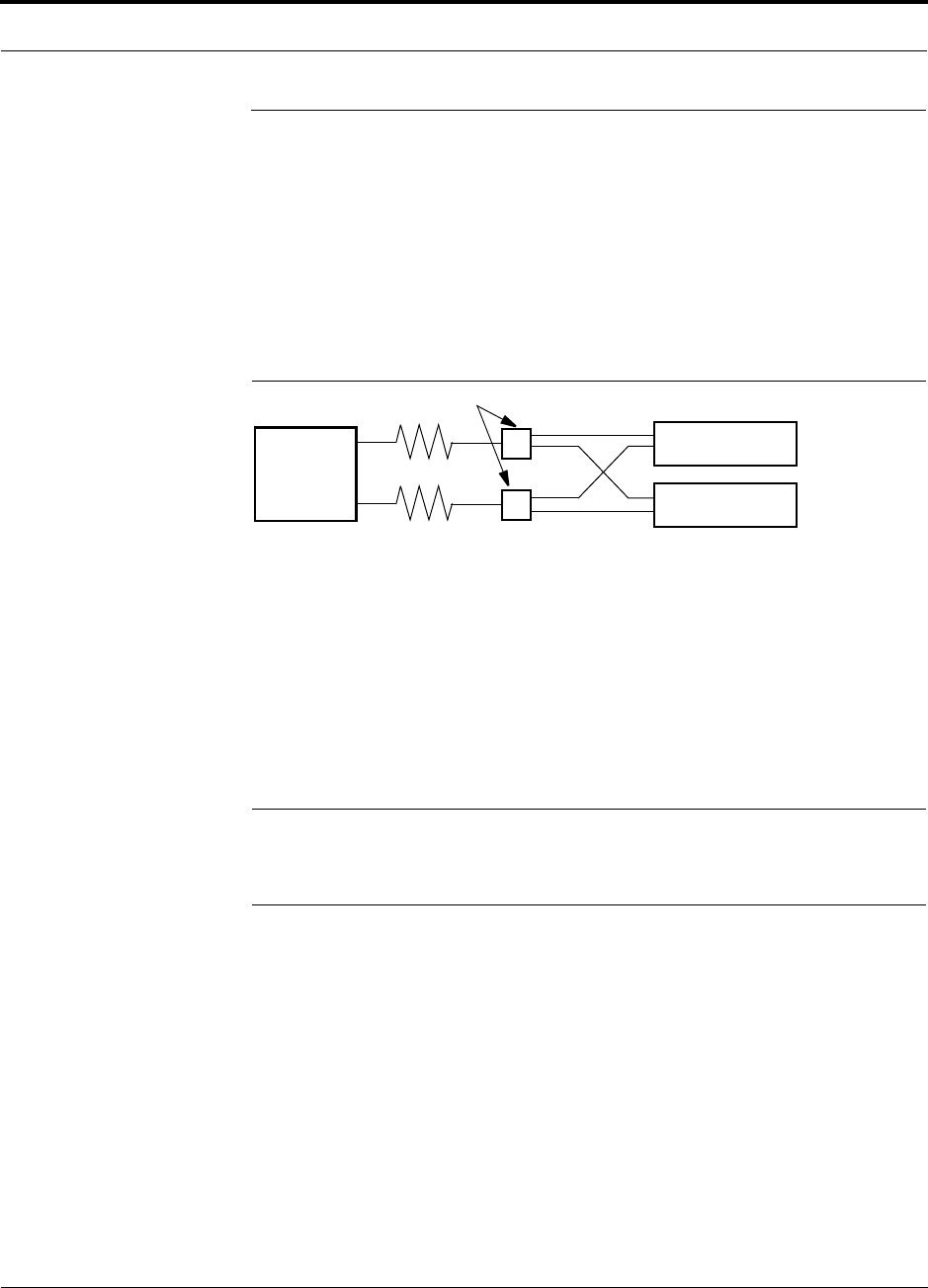
Help Hot Line (U.S. only): 1-800-530-9960 6-39
D-620003-0-20 Rev M CONFIDENTIAL
Connecting a Main Hub to a Base Station
6.6 Connecting a Main Hub to a Base Station
The first consideration when connecting Unison Main Hubs to a base station is to
ensure there is an equal amount of loss through cables, combiners, and so on from the
base station to the Main Hubs. For this example, assume that the base station will
have simplex connections, one uplink and one downlink. Each of these connections
needs to be divided to equilibrate power for each Main Hub. For example, two Main
Hubs require a 2×1 combiner/divider; four Main Hubs require a 4×1 com-
biner/divider; and so on.
Figure 6-2 Connecting Main Hubs to a Simplex Base Station
When connecting a Unison Main Hub to a base station, also consider the following:
1. The downlink power from the base station must be attenuated enough so that the
power radiated by the RAU does not exceed the maximum power per carrier listed
in Section 6.1, “Maximum Output Power Per Carrier at RAU,” on page 6-3.
2. The uplink attenuation should be small enough that the sensitivity of the overall
system is limited by Unison, not by the attenuator. However, some base stations
trigger alarms if the noise or signal levels are too high. In this case the attenuation
has to be large enough to prevent this from happening.
NOTE: The UPLINK and DOWNLINK ports cannot handle a DC power
feed from the base station. If DC power is present, a DC block must be used
or the hub may be damaged.
If, in an area covered by Unison, a mobile phone indicates good signal strength but
consistently has difficulty completing calls, it is possible that the attenuation between
Unison and the base station needs to be adjusted. In other words, it is possible that if
the uplink is over-attenuated, the downlink power will provide good coverage, but the
uplink coverage distance will be small.
When there is an excessive amount of loss between the Main Hub uplink and the base
station, the uplink system gain can be increased to as much as 15 dB to prevent a
reduction in the overall system sensitivity.
Base Station
2 × 1 combiner/divider
Downlink/Forward
Main Hub 1
Main Hub 2
Uplink/Reverse
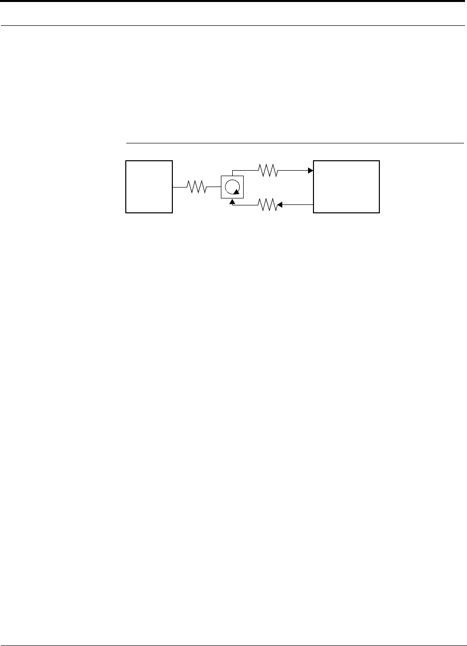
Connecting a Main Hub to a Base Station
6-40 InterReach Unison Installation, Operation, and Reference Manual
CONFIDENTIAL D-620003-0-20 Rev M
6.6.1 Attenuation
Figure 6-3 shows a typical setup wherein a duplex base station is connected to a Main
Hub. For a simplex base station, eliminate the circulator and connect the simplex
ports of the base station to the simplex ports of the Main Hub. Add attenuators to reg-
ulate the power appropriately.
Figure 6-3 Main Hub to Duplex Base Station or Repeater Connections
Duplex
Base Station Main Hub
Forward
Reverse
A3
A1
A2
• A typical circulator has an IP3 of +70dBm. If you drive the circulator too hard it produces
intermods bigger than the intermods produced by Unison. The IP3 at the Forward port input
of the Main Hub is approximately +38 dBm. The IP3 of the circulator at that same point (i.e.,
following attenuator A1) is +70dBm – A1. Thus, to keep the system IP3 from being
adversely affected by the circulator, attenuator A1 should be no more than approximately
+30 dB.
• A filter diplexer can be used in place of the circulator. The IP3 of the diplexer can be
assumed to be greater than +100 dBm. If a diplexer is used, A3 can be omitted.
• A1+A3 should be chosen so that the output power per carrier at the RAU’s output is correct
for the number of carriers being transmitted. Suppose the base station transmits 36 dBm
per carrier and it is desired that the RAU output be 6 dBm per carrier and the forward port
gain is 0 dB. Then A1+A3=30 dB.
• A2+A3 should, ideally, be at least 10 dB less than the noise figure plus the gain of the Uni-
son system. For example, if the reverse port has a 0 dB gain and if there are 32 RAUs, the
noise figure is approximately 22 dB. So A2+A3 should be about 10 dB. If A2+A3 is too
large, the uplink coverage can be severely reduced.
• Given these three equations:
A1 < 30 dB
A1+A3 = 30 dB (in this example)
A2+A3 < 10 dB (in this example)
we could choose A1=20 dB, A2=0 dB, A3=10 dB
or
Repeater

Help Hot Line (U.S. only): 1-800-530-9960 6-41
D-620003-0-20 Rev M CONFIDENTIAL
Connecting a Main Hub to a Base Station
6.6.2 Uplink Attenuation
The attenuation between the Main Hub’s uplink port and the base station does two
things:
• It attenuates the noise coming out of Unison.
• It attenuates the desired signals coming out of Unison.
Setting the attenuation on the uplink is a trade-off between keeping the noise and
maximum signal levels transmitted from Unison to the base station receiver low
while not reducing the SNR (signal-to-noise ratio) of the path from the RAU inputs to
the base station inputs. This SNR can not be better than the SNR of Unison by itself,
although it can be significantly worse.
For example, suppose we have a GSM Unison system consisting of one Main Hub,
four Expansion Hubs, and 32 RAUs (1-4-32) with uplink NF=22 dB. (Refer to
Table 6-32 on page 6-32.) If we use 30 dB of attenuation between the Main Hub’s
uplink port and the base station (which has its own noise figure of about 4 dB), the
overall noise figure is 34.3 dB (refer to the formula on page 6-30) which is 12.3 dB
worse than Unison by itself. That causes a 12.3 dB reduction in the uplink coverage
distance. If the attenuation is 10 dB instead, the cascaded noise figure is NF=22.6 dB,
which implies that the uplink sensitivity is limited by Unison, a desirable condition.
Rule of Thumb
A good rule of thumb is to set the uplink attenuation, A2+A3 in Figure 6-3 on
page 6-40, as follows:
A2+A3 ≈ Unison uplink NF + uplink gain (0 dB for reverse port) – BTS NF – 10dB
and round A2 down to the nearest convenient attenuation value.

Connecting a Main Hub to a Base Station
6-42 InterReach Unison Installation, Operation, and Reference Manual
CONFIDENTIAL D-620003-0-20 Rev M
6.6.2.1 Uplink Attenuation Exception: CDMA
In CDMA systems, the power transmitted by the mobile is determined by the charac-
teristics of both the uplink and downlink paths. The power transmitted by the mobile
should be similar in open-loop control (as determined by the downlink path) as dur-
ing closed-loop control (as determined by the uplink and downlink paths). In addi-
tion, the mobile’s transmit power when it communicates with a base station through
Unison should be similar to the power transmitted when it communicates with a base
station in the outdoor network (during soft hand-off). Because of these consider-
ations, you should not allow the downlink and uplink gains to vary widely.
Open-loop power control:
PTX = –76 dBm (for PCS) – PRX
where PTX is the power transmitted and PRX is the power received by the mobile. If
PL is the path loss (in dB) between the RAU and the mobile, and PDL is the downlink
power radiated by the RAU, then
PTX = –76 dBm (for PCS) – PDL + PL
Closed-loop power control:
PTX = noise floor + uplink NF – process gain + Eb/No + PL
= –113 dBm/1.25 Mhz + NF – 19 dB + 7 dB + PL
where Eb/No = 7 dB is a rough estimate, and NF is the cascaded noise figure of the
Unison uplink, the uplink attenuation, and the base station noise figure. Equating PTX
for the open-loop and closed-loop we see that
NF = 49 – PDL
where PDL is determined by the downlink attenuation. Since PDL for Unison is about
10 dBm, the cascaded noise figure is about 39 dB, which is considerably higher than
that of Unison itself. This implies that we should use a fairly large attenuation on the
uplink. This case suggests using as much attenuation on the downlink as on the
uplink. The drawback is that the uplink coverage sensitivity is reduced. A link budget
analysis clarifies these issues. Typically, the uplink attenuation between the Main
Hub and the base station will be the same as, or maybe 10 dB less than, the downlink
attenuation.

Help Hot Line (U.S. only): 1-800-530-9960 6-43
D-620003-0-20 Rev M CONFIDENTIAL
Connecting a Main Hub to a Base Station
6.6.3 RAU Attenuation and ALC
The RAU attenuation and Automatic Level Control (ALC) are set using the OpsCon-
sole or AdminManager Advanced RAU Settings command.
Embedded within the uplink RF front-end of each Unison Remote Access Unit is an
ALC circuit. This ALC circuit protects the Unison system from overload and exces-
sive intermodulation products due to high-powered mobiles or other signal sources
that are within the supported frequency band and are in close proximity to the RAU.
The Unison uplink ALC circuit operates as a feedback loop. A power detector mea-
sures the level of the uplink RF input and if that level exceeds –30 dBm, an RF atten-
uator is activated. The level of attenuation is equal to the amount that the input
exceeds –30 dBm. The following sequence describes the operation of the ALC cir-
cuit, as illustrated in Figure 6-4.
1. The RF signal level into the RAU rises above the activation threshold
(–30 dBm), causing the ALC loop to enter into the attack phase.
2. During the attack phase, the ALC loop increases the attenuation (0 to 30 dB) until
the detector reading is reduced to the activation threshold. The duration of this
attack phase is called the attack time.
3. After the attack time, the ALC loop enters the hold phase and maintains a fixed
attenuation so long as the high-level RF signal is present.
4. The RF signal level drops below the release threshold (–45 dBm) and the ALC
loop enters the release phase.
5. During the release phase, the ALC loop holds the attenuation for a fixed period
then quickly releases the attenuation.
An important feature of the ALC loop is that in Step 3, the attenuation is maintained
at a fixed level until the signal drops by a significant amount. This prevents the ALC
loop from tracking variations in the RF signal itself and distorting the waveform
modulation.
Figure 6-4 ALC Operation
Input Signal
Level
Activation
Level
-30dBm
Release
Level
-45dBm
Output Signal
Level
Time
Hold
Phase
Release
Phase
Attack
Phase
3
1
2
4
5

Connecting a Main Hub to a Base Station
6-44 InterReach Unison Installation, Operation, and Reference Manual
CONFIDENTIAL D-620003-0-20 Rev M
6.6.3.1 Using the RAU 10 dB Attenuation Setting
Each RAU can, independently of the other RAUs in a system, have its uplink or
downlink gain attenuated by 10dB.1 This is accomplished by selecting the check
boxes in the Advanced RAU Settings dialog box. There are two check boxes: one for
setting the downlink attenuation and another for setting the uplink attenuation.
• Downlink Attenuation
The purpose of the downlink attenuator is to provide a mechanism to reduce the
signal strength from an RAU. For instance, this could be for an RAU located near
a window in a tall building that is causing excessive leakage to the macro-network.
In such a case it is important to attenuate the downlink only. The uplink should not
be attenuated. If the uplink is attenuated, the uplink sensitivity is reduced and
mobile phones in the area of that RAU will have to transmit at a higher power. This
would increase interference to the outdoor network from such mobiles.
• Uplink Attenuation
The purpose of the uplink attenuator is to attenuate environmental noise picked up
by an RAU located in an area where heavy electrical machinery is operating. In
such environments the electrical noise can be quite high and it is useful to reduce
the amount of such noise that gets propagated through the distributed antenna sys-
tem. Attenuating the uplink of an RAU located in areas of high electrical noise
helps preserve the sensitivity of the rest of the system.
The effect of activating the uplink or downlink attenuators is to reduce the coverage
area of the adjusted RAU. The coverage radius will be reduced by roughly a factor of
2. More specifically, if d is the coverage distance without attenuation and d’ is the
coverage radius with the attenuation, then
where PLS is the path loss slope.
1. With UMTS-2 RAU, a higher granularity of gain control is provided in 1dB increments, giving a better gain control and
fine-tuning capability.
PLSdB
d
d/10
10
'=

Help Hot Line (U.S. only): 1-800-530-9960 6-45
D-620003-0-20 Rev M CONFIDENTIAL
Connecting a Main Hub to a Base Station
6.6.3.2 Using the Uplink ALC Setting
Uplink automatic level control (UL ALC) circuitry within the RAU provides auto-
matic level control on high-power signals in the uplink path. This functionality is
required to prevent RF signal compression caused by a single or multiple wireless
devices that are in very close proximity to an RAU. Compression causes signal degra-
dation and, ultimately, bit errors, and should be prevented. Two settings are available
to optimize UL ALC performance:
•Single Operator and Protocol: Use when only one operator and protocol is
on-the-air within the Unison system’s configured and adjacent frequency bands
(rarely used).
•Multiple Operators: Use when more than one operator and/or protocol is present
in the Unison system’s frequency or adjacent frequency bands (almost always
used).
Table 6-35 shows the frequency bands that are adjacent to the bands of which the sys-
tem is configured.
Table 6-35 Frequency Bands Adjacent to System Configured Bands
System
Configuration Adjacent Bands
iDEN Cellular
Cellular iDEN
PCS ADB PCS E
PCS DBEF PCS A, PCS C
PCS EFC PCS B
PCS A4, A5, D, B, E F
PCS A5, D, B, E, F C
PCS D, B, E, F, C2 A
PCS B4, B5, E, F, C A1
DCS 1 DCS 2, DCS 4
DCS 2 DCS 1, DCS 4
DCS4 DCS 1, DCS 2
UMTS 1 UMTS 2, UMTS 3
UMTS 2 UMTS 1, UMTS 3
UMTS 3 UMTS 1, UMTS 2
AWS1 AWS2
AWS2 AWS1
PS700 iDEN, 700 UC
700 UC PS700

Designing for a Neutral Host System
6-46 InterReach Unison Installation, Operation, and Reference Manual
CONFIDENTIAL D-620003-0-20 Rev M
6.7 Designing for a Neutral Host System
Designing for a neutral host system uses the same design rules previously explained.
Since a neutral host system typically uses multiple systems in parallel with common
equipment locations, it is best to design according to the minimum among the sys-
tems’ RAU coverage distances so that there will not be holes in the coverage area,
and so that the economies of a single installation can be achieved. For example, as
indicated in Section 7.1, the 1900 MHz RF signals do not propagate throughout a
building as well as the 800 MHz signals. Therefore, we design using the 1900 MHz
radiated distance, calculated with the path loss slope formula.
The example neutral host system described below consists of one iDEN, one 800
MHz, and two 1900 MHz systems and can support up to seven separate service pro-
viders in the following manner:
•1 on iDEN
• 2 on 800 MHz, A band and B band
• 2 in each of the two 1900 MHz frequency sub-bands
Example Unison Neutral Host System
The following example configuration was designed to provide:
• Similar coverage per band in an office environment that is 80% cubicles and
20% offices.
• Similar capacity.
• Support for up to 7 Operators, where equipment has been shared to minimize
the number of parallel systems.
Example Configuration:
• 800 MHz iDEN: 16 channels (3 dBm)
• 800 MHz Cellular (3 dBm)
TDMA Band: 14 channels (shared)
CDMA Band: 3 channels (shared)
• 1900 MHz PCS (6 dBm)
TDMA Band: 14 channels
CDMA Band: 3 channels (shared)
GSM Band: 6 channels (shared)

Help Hot Line (U.S. only): 1-800-530-9960 6-47
D-620003-0-20 Rev M CONFIDENTIAL
Designing for a Neutral Host System
Similar coverage is achieved by setting the transmit power per carrier of the 800 MHz
systems to 3 dBm per carrier and those of the 1900 MHz systems to 6 dBm per car-
rier.
The numbers of RF carriers were selected in order to match subscriber capacity
approximately. Because each protocol in the example supports a different number of
voice channels, the RF carrier numbers also differ. As Table 6-36 indicates, the 800
MHz Cellular and shared 1900 MHz systems can support additional RF carriers with-
out decreasing the power per carrier figures.
For logistical reasons, operators involved in a neutral host system sometimes prefer
not to share equipment with other operators. From technical and economic perspec-
tives, too, this can be a prudent practice in medium to high-capacity installations.
Though deploying parallel systems appears to increase the amount of equipment
needed as well as the system cost, the trade-off between capacity and coverage must
be considered because, in short, as capacity increases, coverage area per RAU
decreases. Therefore, more RAUs (and perhaps Expansion Hubs and Main Hubs) are
needed to cover a given floor space.
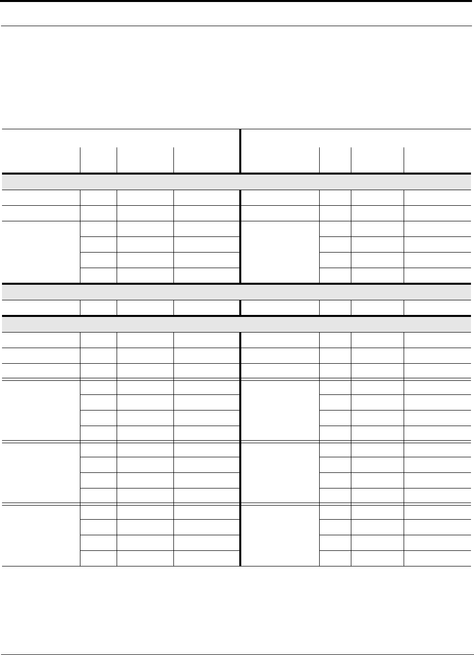
Designing for a Neutral Host System
6-48 InterReach Unison Installation, Operation, and Reference Manual
CONFIDENTIAL D-620003-0-20 Rev M
Table 6-36 shows the capacities of both 800 and 1900 MHz Unison systems used for
single and multiple protocol applications. The power per carrier for each system is
based on providing equal coverage areas for both systems when they are used in an
office building that is 80% cubicles and 20% offices.
Note 1
The RF channel capacity limits are based on the Unison data sheets’ “typical” specifications for fiber length, Cat-5 length, and RF perfor-
mance.
Note 2
The subscriber capacity limits are based on the Erlang B traffic model with a 2% GOS. Each user has a 50mErlangs, which is higher than
the standard 35mErlangs.
Table 6-36 Unison Capacity: Equal Coverage Areas
Operator #1 Operator #2
Protocol RF
Chs Voice Chs Subscribers Protocol RF
Chs Voice Chs Subscribers
800 MHz Cellular A/B (Unison); 3 dBm power per carrier
TDMA only 35 104 1837 N/A —— —
CDMA only 12 180–240 3327–4517 N/A —— —
TDMA
(combining with CDMA:
Operator #2)
15 44 694 CDMA
(combining with TDMA:
Operator #1)
10 150–200 2736–3723
20 59 974 7 105–140 1856–2540
25 74 1259 4 60–80 993–1374
28 83 1431 2 30–40 439–620
800 MHz iDEN (Unison); 3 dBm power per carrier
iDEN only 16 47 749 N/A —— —
1900 MHz PCS (Unison); 6 dBm power per carrier
TDMA only 14 41 638 N/A —— —
CDMA only 10 150–200 2736–3723 N/A —— —
GSM only 14 111 1973 N/A —— —
TDMA
(combining with CDMA:
Operator #2)
617 213 CDMA
(combining with TDMA:
Operator #1)
4 60–80 993–1374
8 23 315 3 45–60 712–993
10 29 421 2 30–40 439–620
11 32 474 1 15–20 180–264
TDMA
(combining with GSM:
Operator #2)
617 213 GSM
(combining with TDMA:
Operator #1)
755 899
823 315 539 602
10 29 421 3 23 315
11 32 474 2 15 180
CDMA
(combining with GSM:
Operator #2)
2 30–40 439–620 GSM
(combining with CDMA:
Operator #1)
10 79 1355
4 60–80 993–1374 7 55 899
6 90–120 1566–2148 4 31 457
8 120–200 2148–2933 1 7 59

InterReach Unison Installation, Operation, and Reference Manual 7-1
D-620003-0-20 Rev M CONFIDENTIAL
SECTION 7 Installing Unison
7.1 Installation Requirements
Before and during installation, keep in mind the following sources of potential prob-
lems:
• Faulty cabling/connector
• Dirty connectors and ports
• Malfunction of one or more Unison components
• Antenna, base station, or repeater problem
• External RF interface
• Tripped circuit breaker
• Equipment is not grounded
• Using a Null modem cable that does not support full hardware handshaking when
using AdminManager
NOTE: Faulty cabling is the cause of a majority of problems. All Cat-5E/6 cable
should be tested to TIA/EIA 568-A specifications. The RAU will be damaged if the
cable is not wired correctly.

Installation Requirements
7-2 InterReach Unison Installation, Operation, and Reference Manual
CONFIDENTIAL D-620003-0-20 Rev M
7.1.1 Component Location Requirements
Unison components are intended to be installed in indoor locations only.
7.1.2 Cable and Connector Requirements
The Unison equipment operates over:
• Category 5E or 6 (Cat-5E/6) screened twisted pair (ScTP) cable with shielded
RJ-45 connectors
• Single-mode fiber (SMF) or multi-mode fiber (MMF) cable with SC/APC fiber
connectors throughout the fiber network, including fiber distribution panels
These cables are widely used industry standards for Local Area Networks (LANs).
The regulations and guidelines for Unison cable installation are identical to those
specified by the TIA/EIA 568-A standard and the TIA/EIA/IS-729 supplement for
LANs.
ADC recommends plenum-rated Cat-5E/6 ScTP and fiber cable and connectors for
conformity to building codes and standards.
Belden 1533P DataTwist® Five ScTP cable, or equivalent is required for Cat-5E.
Commscope® 5ES4/5ENS4 may also be used for Cat-5E.
NOTE: In order to meet FCC and CE Mark emissions requirements, the Cat-5E/6
cable must be screened (ScTP) and it must be grounded using shielded RJ-45 con-
nectors at both ends.
7.1.3 Multiple Operator System Recommendations
As in any Unison system, a multiple operator (neutral host) system requires one pair
of fiber strands between each Main Hub and each Expansion Hub, and one Cat-5E/6
cable between each Expansion Hub and each RAU. In situations where Hubs and/or
RAUs will be installed in the future to support the addition of frequency bands and/or
wireless Operators, it is advantageous to install the necessary cabling initially. Such
deployment typically leads to substantial cost savings over installing parallel cabling
at separate times.
7.1.4 Distance Requirements
Table 7-1 shows the distances between Unison components and related equipment.

Help Hot Line (U.S. only): 1-800-530-9960 7-3
D-620003-0-20 Rev M CONFIDENTIAL
Installation Requirements
Table 7-1 Unison Distance Requirements
Equipment
Combination Cable Type Distance Additional Information
Repeater to Main
Hub Coaxial; N male
connectors 3–6 m (10–20 ft) typical Limited by loss and noise.
Refer to your link budget
calculation.
10 m (33 ft) maximum Limited by CE Mark require-
ments.
Base Station to Main
Hub Coaxial; N male
connectors 3–6 m (10–20 ft) typical Limited by loss and noise.
Refer to your link budget
calculation.
10 m (33 ft) maximum Limited by CE Mark require-
ments.
Main Hub to
Expansion Hub Multi-mode Fiber:
Single-mode Fiber:
SC/APC male
connectors
1.5 km (4,921 ft) max.
6 km (19,685 ft) max. Limited by 3 dB optical loss.
Expansion Hub to
RAU Cat-5E/6 ScTP;
shielded RJ-45 male
connectors
• Minimum: 10 meters (33 ft)
• Recommended Max.: 100 meters (328 ft)
See Section 7.4.5 if using a Cat-5 Extender
Refer to “System Gain (Loss)
Relative to ScTP Cable
Length” on page 6-25.
RAU to passive
antenna Coaxial; SMA male
connectors 1–3.5 m (3–12 ft) typical Limited by loss and noise.
Refer to your link budget
calculation.

Safety Precautions
7-4 InterReach Unison Installation, Operation, and Reference Manual
CONFIDENTIAL D-620003-0-20 Rev M
7.2 Safety Precautions
7.2.1 Installation Guidelines
Use the following guidelines when installing ADC equipment:
• Provide sufficient airflow and cooling to the equipment to prevent heat build-up
from exceeding the maximum ambient air temperature specification. Do not com-
promise the amount of airflow required for safe operation of the equipment.
• If you are removing the system, turn it off and remove the power cord first. There
are no user-serviceable parts inside the components.
• The internal power supply has internal fuses that are not user replaceable. Consider
the worst-case power consumption shown on the product labels when provisioning
the equipment’s AC power source and distribution.
7.2.2 General Safety Precautions
The following precautions apply to ADC products:
• The units have no user-serviceable parts. Faulty or failed units are fully replaceable
through ADC. Please contact ADC at:
1-800-530-9960 (U.S. only)
+1-408-952-2400 (International)
• Although modeled after an Ethernet/LAN architecture and connectivity, the units
are not intended to connect to Ethernet data hubs, routers, cards, or other similar
data equipment.
• When you connect the fiber optic cable, take the same precaution as if installing
Ethernet network equipment. All optical fiber SC/APC connectors should be
cleaned according to the cable manufacturer’s instructions.
• When you connect a radiating antenna to an RAU, firmly hand-tighten the SMA
female connector – DO NOT over-tighten the connector.
WARNING: To reduce the risk of fire or electric shock, do not
expose this equipment to rain or moisture. The components are
intended for indoor use only. Do not install the RAU outdoors. Do not
connect an RAU to an antenna that is located outside where it could
be subject to lightning strikes, power crosses, or wind.
Help Hot Line (U.S. only): 1-800-530-9960 7-5
D-620003-0-20 Rev M CONFIDENTIAL
Safety Precautions
7.2.3 Fiber Port Safety Precautions
The following are suggested safety precautions for working with fiber ports. For
information about system compliance with safety standards, refer to Appendix B.
WARNING: Observe the following warning about viewing fiber
ends in ports. Do not stare with unprotected eyes at the connector
ends of the fibers or the ports of the hubs. Invisible infrared radia-
tion is present at the front panel of the Main Hub and the Expansion
Hub. Do not remove the fiber port dust caps unless the port is going
to be used. Do not stare directly into a fiber port.
•Test fiber cables: When you test fiber optic cables, connect the optical power
source last and disconnect it first. Use Class 1 test equipment.
•Fiber ends: Cover any unconnected fiber ends with an approved cap. Do not use
tape.
•Broken fiber cables: Do not stare with unprotected eyes at any broken ends of the
fibers. Laser light emitted from fiber sources can cause eye injury. Avoid contact
with broken fibers; they are sharp and can pierce the skin. Report any broken fiber
cables and have them replaced.
•Cleaning: Be sure the connectors are clean and free of dust or oils. Use only
approved methods for cleaning optical fiber connectors.
•Modifications: Do not make any unauthorized modifications to this fiber optic
system or associated equipment.
•Live work: Live work is permitted because ADC equipment is a Class 1 hazard.
•Signs: No warning signs are required.
•Class 1 laser product: The system meets the criteria for a Class 1 laser product
per IEC 60825-1:1998-01 and IEC 60825-2:2000-05.
In addition, it is certified by the FDA to meet 21CFR, Chapter 1, Subchapter J.
•CAUTION: Use of controls or adjustments or performance of procedures other
than those specified herein may result in hazardous radiation exposure.
This label appears on the front panel of the
Main Hub and the Expansion Hub.
CLASS 1
LASER PRODUCT
This example label
of the Main Hub and a
appears on the bottom
similar one appears
on the bottom of the
Expansion Hub

Preparing for System Installation
7-6 InterReach Unison Installation, Operation, and Reference Manual
CONFIDENTIAL D-620003-0-20 Rev M
7.3 Preparing for System Installation
7.3.1 Pre-Installation Inspection
Follow this procedure before installing Unison equipment:
1. Verify the number of packages received against the packing list.
2. Check all packages for external damage; report any external damage to the ship-
ping carrier. If there is damage, a shipping agent should be present before you
unpack and inspect the contents because damage caused during transit is the
responsibility of the shipping agent.
3. Open and check each package against the packing slip. If any items are missing,
contact ADC customer service.
4. If damage is discovered at the time of installation, contact the shipping agent.
7.3.2 Installation Checklist
Table 7-2 Installation Checklist
3Installation Requirement Consideration
Floor Plans Installation location of equipment clearly marked
System Design Used to verify frequency bands after installation
Power available**:
Main Hub (AC)
Expansion Hub (AC)
To RAU (DC)
Power cord is 2 m (6.5 ft) long**.
Rating: 100–240V, 0.5A, 50–60 Hz
Rating: 115/230V, 5/2.5A, 50–60 Hz
36V (from the Expansion Hub)
Rack space available:
Main Hub
Expansion Hub 44 mm (1.75 in.) high (1U)
89 mm (3.5 in.) high (2U)
Clearance for air circulation:
Main and Expansion Hubs
RAU 76 mm (3 in.) front and rear, 51 mm (2 in.) sides
76 mm (3 in.) all around
Suitable operating environment**:
Main and Expansion Hubs
RAUs
Indoor location only
0° to +45°C (+32° to +113°F)
5% to 95% non-condensing humidity
–25° to +45°C (–13° to +113°F)
5% to 95% non-condensing humidity
Donor Antenna-to-Unison Configuration
Donor Antenna Installed, inspected; N-male to N-male coaxial cable to lightning arrestor/surge
suppressor
Lightning Arrestor or
Surge Suppressor Installed between roof-top antenna and repeater; N-male to N-male coaxial cable
Repeater Installed between lightning arrestor/surge suppressor and Main Hub; N-male to
N-male coaxial cable

Help Hot Line (U.S. only): 1-800-530-9960 7-7
D-620003-0-20 Rev M CONFIDENTIAL
Preparing for System Installation
Attenuator Installed between the circulator and the Main Hub downlink port to prevent
overload. Optionally, it may be installed between the uplink port and the circula-
tor
Circulator or Duplexer Installed between the repeater and the Main Hub uplink and downlink ports
Base Station-to-Unison Configuration
Base Station Verify RF power (refer to the tables in Section 6.1 on page 6-3); N-male to
N-male coaxial cable; installed, inspected
Attenuator Attenuation may be required to achieve the desired RF output at the RAU and
the desired uplink noise floor level
Circulator or Duplexer When using a duplex BTS: Installed between the BTS and the Main Hub uplink
and downlink ports. Not used with a simplex BTS
** For Japan, see separate addendum - Japan Specification Document - for power cord use.
Connecting LGCell Main Hub(s) to a Unison Main Hub
5-port Alarm Daisy-Chain Cable
(PN 4024-3) For normally closed (NC) contact alarm monitoring: connecting 2 to 21 LGCell
Main Hubs to a Unison Main Hub
If connecting LGCell to Unison, the Alarm Sense Adapter Cable is required to
connect the daisy-chain cable to Unison
Do not combine LGCell Main Hubs with Unison Main Hubs in the same daisy
chain
Alarm Sense Adapter Cable
(PN 4024-3) Use with 5-port Alarm Daisy-Chain Cable to connect up to 21 LGCell Main
Hubs to a Unison Main Hub
Also, use this cable to connect a single LGCell Main Hub to a Unison Main Hub
Connecting Multiple Unison Main Hubs Together
5-port Alarm Daisy-Chain Cable
(PN 4024-3) For normally closed (NC) contact alarm monitoring of fault and warning alarms.
Use to feed the alarms from multiple Unison Main Hubs into a BTS or Flex-
Wave Focus
Do not combine Unison Main Hubs with LGCell Main Hubs in the same chain.
Cabling
Coaxial: repeater or base station to
Main Hub Coax approved; N-type male connectors
Coaxial: RAU to passive antennas Use low-loss cable; SMA male connector; typical 1 m (3.3 ft) using RG142
coaxial cable
Table 7-2 Installation Checklist (continued)
3Installation Requirement Consideration

Preparing for System Installation
7-8 InterReach Unison Installation, Operation, and Reference Manual
CONFIDENTIAL D-620003-0-20 Rev M
Fiber: Main Hub to Expansion Hubs SC/APC (angle-polished) male connectors for entire fiber run (can use SC/APC
pigtails, PN 4012SCAPC-10 for MMF or 4013SCAPC-10 for SMF);
Use jumper fiber cables for collocated Main and Expansion Hubs (3 m/10 ft):
Multi-mode: PN 4010SCAPC-10
Single-mode: PN: 4018SCAPC-10
Distance limited by optical loss of 3 dB:
Multi-mode: up to 1.5 km (4,921 ft);
Single-mode: up to 6 km (19,685 ft)
Cat-5E/6 ScTP: TIA/EIA 568-A approved; shielded RJ-45 male connectors. ScTP cable must be
screened and it must be grounded at both connector ends
Tie-off cables to avoid damaging the connectors because of cable strain
Expansion Hub to RAUs • Minimum: 10 meters (33 ft)
• Recommended Maximum: 100 meters (328 ft)
Cat-5E/6 ScTP: Expansion Hub
to Cat-5 Extender to RAU**
Configuring System
PC/laptop running AdminManager
software Refer to the AdminManager User Manual (PN 8810-10)
Miscellaneous
Null modem cable Female connectors; Main Hub to a PC/laptop that is running the AdminManager
software; local connection
Straight-through cable Female/male connectors; Main Hub to a modem; remote connection
Cat-5 Extender Used if Cat-5E/6 run(s) will exceed 100 meters
Dual-Band Diplexer Used in dual band systems to combine the output of a low-band RAU and a
high-band RAU to a single dual band antenna
Distances
Main Hub is within 3–6m (10–20 ft)
of connecting repeater If longer distance, determine the loss of the cable used for this connection and
adjust the RF signal into the Main Hub accordingly. This can be done by read-
justing the power from the base station, or by changing the attenuation value
between the base station/repeater and the Main Hub
Main Hub is within 3–6m (10–20 ft)
of connecting base station
Main Hub is within correct distance of Expansion Hub(s);
SMF and MMF optical link budget: 3 dB
Table 7-2 Installation Checklist (continued)
3Installation Requirement Consideration
Minimum Cat-5E/6
Cable Length from
Expansion Hub to
Extender
Minimum Cat-5E/6
Cable Length from
Extender to RAU
Maximum Total
Cat-5E/6 Cable Length
from Expansion Hub
to RAU
90 meters
295 feet
20 meters
65 feet
110 to 170 meters
360 to 557 feet
** For Japan, see separate addendum - Japan Specification Document.

Help Hot Line (U.S. only): 1-800-530-9960 7-9
D-620003-0-20 Rev M CONFIDENTIAL
Preparing for System Installation
7.3.3 Tools and Materials Required
7.3.4 Optional Accessories
Table 7-3 Tools and Materials Required for Component Installation
3Description
Cable ties
Phillips screwdriver
7-inch lb. torch wrench
Mounting screws and spring nuts
Fiber cleaning supplies: compressed air; isopropyl alcohol; lint-free cloths;
2.5mm lint-free, foam tipped swabs;
Compressed air
Screws, anchors (for mounting RAUs)
Drill
Fiber connector cleaning kit
Fusion splicer
Splicing tool kit (including: snips, cladding strippers, fiber cleaver, isopropyl alcohol,
lint-free wipes)
Fusion splicing sleeves
Table 7-4 Optional Accessories for Component Installation
3Description
Wall-mount equipment rack(s) (PN 4712)
Note that if using this rack with an Expansion Hub, the Hub’s mounting bracket must
be moved to the center mounting position.
Cable management (Cable manager: PN 4759; Tie wrap bar: PN 4757)
Splice trays
Pigtails with SC/APC connectors, 3 m (10 ft):
Multi-mode Fiber SC/APC Pigtail (PN 4012SCAPC-10)
Single-mode Fiber SC/APC Pigtail (PN 4013SCAPC-10)
Jumper cable when Main and Expansion Hubs are collocated, 3 m (10 ft):
Single-mode Fiber SC/APC (PN 4018SCAPC-10)
Teltone Line Sharing Switch (M-394-B-01)
When using a single POTS line with multiple Main Hub/Modems: Connect up to four
modems to a line sharing switch; can cascade switches to accommodate up to 16
modems per POTS line

Preparing for System Installation
7-10 InterReach Unison Installation, Operation, and Reference Manual
CONFIDENTIAL D-620003-0-20 Rev M
Alarm Cables:
5-port Alarm Daisy-Chain Cable (PN 4024-3)
Alarm Sense Adapter Cable (PN 4025-1)
RAU Dust Cover (PN UNS-1RDP-1)
Table 7-4 Optional Accessories for Component Installation (continued)
3Description

Help Hot Line (U.S. only): 1-800-530-9960 7-11
D-620003-0-20 Rev M CONFIDENTIAL
Unison Component Installation Procedures
7.4 Unison Component Installation Procedures
The following procedures assume that the system is new from the factory.
If you are replacing components in a pre-installed system with either new units or
units that may already be programmed (that is, re-using units from another system),
refer to Section 8.
• Installing a Main Hub . . . . . . . . . . . . . . . . . . . . . . . . . . . . . . . . . . . . . . . . . . . . 7-13
• Installing a Main Hub in a Rack . . . . . . . . . . . . . . . . . . . . . . . . . . . . . . . . . 7-13
• Installing an Optional Cable Manager in the Rack . . . . . . . . . . . . . . . . . . 7-13
• Connecting the Fiber Cables to the Main Hub . . . . . . . . . . . . . . . . . . . . . . 7-14
• Installing Expansion Hubs . . . . . . . . . . . . . . . . . . . . . . . . . . . . . . . . . . . . . . . . 7-18
• Installing an Expansion Hub in a Rack . . . . . . . . . . . . . . . . . . . . . . . . . . . 7-18
• Installing an Expansion Hub in a Wall-Mounted Rack . . . . . . . . . . . . . . . 7-18
• Installing an Optional Cable Manager in the Rack . . . . . . . . . . . . . . . . . . 7-19
• Powering On the Expansion Hub . . . . . . . . . . . . . . . . . . . . . . . . . . . . . . . . 7-19
• Connecting the Fiber Cables to the Expansion Hub . . . . . . . . . . . . . . . . . . 7-20
• Connecting the ScTP Cables . . . . . . . . . . . . . . . . . . . . . . . . . . . . . . . . . . . 7-21
• Troubleshooting Expansion Hub LEDs During Installation . . . . . . . . . . . 7-22
• Installing RAUs . . . . . . . . . . . . . . . . . . . . . . . . . . . . . . . . . . . . . . . . . . . . . . . . 7-23
• Installing RAUs . . . . . . . . . . . . . . . . . . . . . . . . . . . . . . . . . . . . . . . . . . . . . 7-23
• Installing Passive Antennas . . . . . . . . . . . . . . . . . . . . . . . . . . . . . . . . . . . . 7-23
• Connecting the Antenna to the RAU . . . . . . . . . . . . . . . . . . . . . . . . . . . . . 7-25
• Connecting the ScTP Cable . . . . . . . . . . . . . . . . . . . . . . . . . . . . . . . . . . . . 7-25
• Troubleshooting RAU LEDs During Installation . . . . . . . . . . . . . . . . . . . . 7-26
• Installing RAUs in a Dual Band System . . . . . . . . . . . . . . . . . . . . . . . . . . 7-27
• Connecting the Antenna to the Dual Band Diplexer . . . . . . . . . . . . . . . . . 7-29
• Configuring the System . . . . . . . . . . . . . . . . . . . . . . . . . . . . . . . . . . . . . . . . . . 7-30
• Configuring the Installed System . . . . . . . . . . . . . . . . . . . . . . . . . . . . . . . . 7-31
The following procedure is for splicing pigtails to fiber cable.
• Splicing Fiber Optic Cable . . . . . . . . . . . . . . . . . . . . . . . . . . . . . . . . . . . . . . . . 7-33
• Fusion Splicing of Fiber and Pigtail . . . . . . . . . . . . . . . . . . . . . . . . . . . . . . 7-33

Unison Component Installation Procedures
7-12 InterReach Unison Installation, Operation, and Reference Manual
CONFIDENTIAL D-620003-0-20 Rev M
The following procedures assume that the system is installed and programmed.
• Interfacing a Main Hub to a Base Station or a Roof-top Antenna . . . . . . . . . . 7-35
• Connecting a Main Hub to an In-Building Base Station . . . . . . . . . . . . . . 7-35
• Connecting a Main Hub to Multiple Base Stations . . . . . . . . . . . . . . . . . . 7-37
• Connecting a Main Hub to a Roof-top Antenna . . . . . . . . . . . . . . . . . . . . . 7-37
• Connecting Multiple Main Hubs . . . . . . . . . . . . . . . . . . . . . . . . . . . . . . . . . . . 7-38
• Connecting Multiple Main Hubs to a Simplex Repeater or Base Station . 7-38
• Connecting Multiple Main Hubs to a Duplex Repeater or Base Station . . 7-40
• Connecting Contact Alarms to a Unison System . . . . . . . . . . . . . . . . . . . . . . . 7-42
• Alarm Source . . . . . . . . . . . . . . . . . . . . . . . . . . . . . . . . . . . . . . . . . . . . . . . 7-43
• Alarm Sense . . . . . . . . . . . . . . . . . . . . . . . . . . . . . . . . . . . . . . . . . . . . . . . . 7-46
• Alarm Cables . . . . . . . . . . . . . . . . . . . . . . . . . . . . . . . . . . . . . . . . . . . . . . . 7-49
• Alarm Monitoring Connectivity Options . . . . . . . . . . . . . . . . . . . . . . . . . . . . . 7-51
• Direct Connection . . . . . . . . . . . . . . . . . . . . . . . . . . . . . . . . . . . . . . . . . . . . 7-51
• Modem Connection . . . . . . . . . . . . . . . . . . . . . . . . . . . . . . . . . . . . . . . . . . 7-52
• RS-232 Port Expander Connection . . . . . . . . . . . . . . . . . . . . . . . . . . . . . . 7-53
• POTS Line Sharing Switch Connection . . . . . . . . . . . . . . . . . . . . . . . . . . . 7-54
• Ethernet and ENET/RS-232 Serial Hub Connection . . . . . . . . . . . . . . . . . 7-55
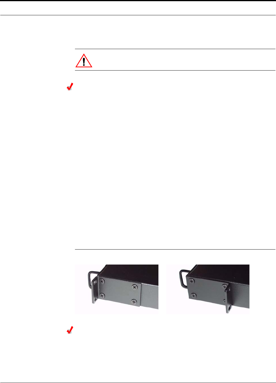
Help Hot Line (U.S. only): 1-800-530-9960 7-13
D-620003-0-20 Rev M CONFIDENTIAL
Unison Component Installation Procedures
7.4.1 Installing a Main Hub
CAUTION: Install Main Hubs in indoor locations only.
Installing a Main Hub in a Rack
Install the Main Hub (1U high) in a standard 19 in. (483 mm) equipment rack. Allow
clearance of 76 mm (3 in.) front and rear, and 51 mm (2 in.) on both sides for air cir-
culation. No top and bottom clearance is required.
Consideration:
• The Main Hub is shipped with #10-32 mounting screws. Another common rack
thread is #12-24. Confirm that the mounting screws match the rack’s threads.
To install the hub in a rack:
1. Insert spring nuts into the rack where needed or use existing threaded holes.
2. Place the Main Hub into the rack from the front.
3. Align the flange holes with the spring nuts installed in Step 1.
4. Insert the mounting screws in the appropriate positions in the rack.
5. Tighten the mounting screws.
Rack-mounting Option
You can flip the rack mounting brackets, as shown in Figure 7-1, so the hub can be
mounted 76 mm (3 in.) forward in the rack.
Figure 7-1 Mounting Bracket Detail
Installing an Optional Cable Manager in the Rack
• Using the screws provided, fasten the cable manager to the rack, immediately
above or below the Main Hub.

Unison Component Installation Procedures
7-14 InterReach Unison Installation, Operation, and Reference Manual
CONFIDENTIAL D-620003-0-20 Rev M
Connecting the Fiber Cables to the Main Hub
Considerations:
• Before connecting the fiber cables, confirm that their optical loss does not exceed
the 3 dB optical budget.
• If you are using fiber distribution panels, confirm that the total optical loss of fiber
cable, from the Main Hub through distribution panels and patch cords to the
Expansion Hub, does not exceed the optical budget.
• Make sure the fiber cable’s connectors are SC/APC (angle-polished). Using any
other connector type will result in degraded system performance and may damage
the equipment. (You can use an SC/APC pigtail if the fiber cable’s connectors are
not SC/APC. Refer to“Fusion Splicing of Fiber and Pigtail” on page 7-33. Or, you
can change the fiber’s connector to SC/APC.)
NOTE: Observe all Fiber Port Safety Precautions listed in Section 7.2.3 on page 7-5.
To clean the fiber ports:
You can clean the Hub’s fiber ports using canned compressed air or isopropyl alcohol
and foam tipped swabs.
Considerations:
• If using compressed air:
• The air must be free of dust, water, and oil.
• Hold the can level during use.
• If using isopropyl alcohol and foam tipped swabs:
• Use only 98% pure or more alcohol
Procedure using compressed air:
1. Remove the port’s dust cap.
2. Spray the compressed air away from the unit for a few seconds to clean out the
nozzle and then blow dust particles out of each fiber port.
Procedure using isopropyl alcohol:
1. Remove the connector’s dust cap.
2. Dip a 2.5mm lint-free, foam-tipped swab in isopropyl alcohol and slowly insert
the tip into the connector.
3. Gently twist the swab to clean the port.
4. Insert a dry swab into the port to dry it.
Additionally, you can use compressed air after the alcohol has completely evapo-
rated.

Help Hot Line (U.S. only): 1-800-530-9960 7-15
D-620003-0-20 Rev M CONFIDENTIAL
Unison Component Installation Procedures
To clean the fiber ends:
Be sure that the fiber cable’s SC/APC connectors are clean and free of dust and oils.
You need lint-free cloths, isopropyl alcohol, and compressed air
1. Moisten a lint-free cloth with isopropyl alcohol.
2. Gently wipe the fiber end with the moistened cloth.
3. Using a dry lint-free cloth, gently wipe the fiber end.
4. Spray the compressed air away from the connector for a few seconds to clean out
the nozzle and then use it to completely dry the connector.
To test the fiber cables:
Perform cable testing and record the results. Test results are required for the final
As-Built Document.
To connect the fiber cables:
The fiber cable is labeled with either 1 or 2, or is color-coded. In addition to these
labels, you should add a code that identifies which port on the Main Hub is being
used and which Expansion Hub the cables are intended for. This differentiates the
connectors for proper connection between the Main Hub and Expansion Hubs.
For example:
First pair to Main Hub port 1: 11 (uplink), 12 (downlink);
Second pair to Main Hub port 2: 21 (uplink), 22 (downlink);
Third pair to Main Hub port 3: 31 (uplink), 32 (downlink); and so on.
If the fiber jumper is labeled with 1 or 2:
1. Connect 1s to UPLINK ports on the Main Hub.
2. Connect 2s to DOWNLINK ports on the Main Hub.
3. Record which cable number and port number you connected to UPLINK and
DOWNLINK.
This information is needed when connecting the other end of the fiber cable to the
Expansion Hub’s fiber ports.
The fiber port LEDs should be off, indicating that the Expansion Hub(s) are not
connected.
If the fiber jumper is color-coded (for example, “blue” or “red”):
1. Connect “blue” to UPLINK ports on the Main Hub.
2. Connect “red” to DOWNLINK ports on the Main Hub.
3. Record which color and port number you connected to UPLINK and DOWNLINK.
This information is needed when connecting the other end of the fiber cable to the
Expansion Hub’s fiber ports.
The fiber port LEDs should be off, indicating that the Expansion Hub(s) are not
connected.

Unison Component Installation Procedures
7-16 InterReach Unison Installation, Operation, and Reference Manual
CONFIDENTIAL D-620003-0-20 Rev M
Powering On the Main Hub
1. Connect the AC power cord to the Main Hub.
2. Plug the power cord into an AC power outlet.
3. Turn on the power to the Main Hub and check that all the LED lamps are func-
tioning properly.
Upon power-up, the LEDs blinks for five seconds as a visual check that they are
functioning. After the five-second test:
LED states during power on will vary, depending on whether Expansion Hubs are
connected. Refer to Table 7-5 for possible combinations.
Table 7-5 Troubleshooting Main Hub LEDs During Installation
During
Installation
Power On LED State Action Impact
1.
Main Hub
power is
On with no
Expansion
Hubs con-
nected.
POWER
Off Check AC power; check that the Main Hub power-on
switch is on; replace the Main Hub The Main Hub is not
powering on.
POWER Red Replace the Main Hub The power supply is
out-of-specification.
LINK
LEDs are on
but they
didn’t blink
through all
states
Replace the Main Hub. The micro controller is
not resetting properly;
flash memory cor-
rupted.
E-HUB/RAU
LINK
Red The port is unusable; replace the Main Hub when
possible. Fiber sensor fault, do
not use the port.
E-HUB/RAU
Off

Help Hot Line (U.S. only): 1-800-530-9960 7-17
D-620003-0-20 Rev M CONFIDENTIAL
Unison Component Installation Procedures
7.4.1.1 Installing Main Hubs in a Multiple Operator System
Installing Main Hubs in a multiple operator system is the same as described in
Section 7.4.1 on page 7-13.
We recommend mounting all multiple operator system Main Hubs in the same
rack(s), grouped by frequency or wireless carrier. For example, group the Main Hubs
for the 800 MHz cellular bands together, and so on.
Connecting to base stations and repeaters is the same as described in Section 7.6 on
page 7-35 and Section 7.6.1 on page 7-38.
2.
Main Hub
power is
On with
Expansion
Hubs con-
nected and
powered
on.
LINK
Off • If the port LEDs do not illuminate, check the fiber
uplink for excessive optical loss.
• If Expansion Hub’s
DL STATUS
LED is red:
• Verify that the fiber is connected to the correct
port (that is, uplink/downlink)
• Swap the uplink and downlink cables.
• Connect the fiber pair to another port. If the sec-
ond port’s LEDs do not illuminate Green/Red,
replace the Main Hub.
• If the second port works, flag the first port as
unusable; replace the Main Hub when possible.
No uplink optical
power, the Expansion
Hub is not recognized
as being present.
No communication
with the Expansion
Hub.
E-HUB/RAU
Off
LINK
Red • If the Expansion Hub
DL STATUS
LED is red,
check the downlink fiber cable for excessive opti-
cal loss.
• Connect the fiber pair to another port. If the sec-
ond port’s LEDs do not illuminate Green/Red,
replace the Main Hub.
• If the second port works, flag the first port as
unusable; replace the Main Hub when possible.
No communication
with the Expansion
Hub.
E-HUB/RAU
Off
LINK
Green The Expansion Hub or connected RAU reports a fault
Use AdminManager to determine the problem.
The Expansion Hub or
one or more RAUs are
off-line.
E-HUB/RAU
Red
Table 7-5 Troubleshooting Main Hub LEDs During Installation (continued)
During
Installation
Power On LED State Action Impact
Unison Component Installation Procedures
7-18 InterReach Unison Installation, Operation, and Reference Manual
CONFIDENTIAL D-620003-0-20 Rev M
7.4.2 Installing Expansion Hubs
The Expansion Hub (2U high) can be installed in a standard 19 in. (483 mm) equip-
ment rack or in a wall-mountable equipment rack that is available from ADC. Allow
a clearance of 76 mm (3 in.) front and rear and 51 mm (2 in.) sides for air circulation.
No top and bottom clearance is required.
Install the Expansion Hub in a horizontal position only.
CAUTION: Install Expansion Hubs in indoor locations only.
Installing an Expansion Hub in a Rack
Consideration:
• The Expansion Hub is shipped with #10-32 mounting screws. Another common
rack thread is #12-24. Confirm that the mounting screws match the rack’s threads.
• If you want to move the mounting brackets to a mid-mounting position, refer to
Installing an Expansion Hub in a Wall-Mounted Rack on page 7-18.
To install the hub in a rack:
1. Insert spring nuts into the rack where needed or use existing threaded holes.
2. Place the Expansion Hub into the rack from the front.
3. Align the flange holes with the spring nuts installed in Step 1.
4. Insert the mounting screws in the appropriate positions in the rack.
5. Tighten the mounting screws.
Installing an Expansion Hub in a Wall-Mounted Rack
Considerations:
• The rack and the Expansion Hub are both 305 mm (12 in.) deep. You must move
the rack mounting brackets on the Expansion Hub to the center mounting position
to allow for the 76 mm (3 in.) rear clearance that is required.
• The maximum weight the rack can hold is 22.5 kg (50 lbs).
To install the hub in a wall-mounted rack:
1. Attach the equipment rack to the wall using the screws that are provided.
The rack must be positioned so that the Expansion Hub will be in a horizontal
position when it is installed.
2. Remove both of the rack mounting brackets from the hub.
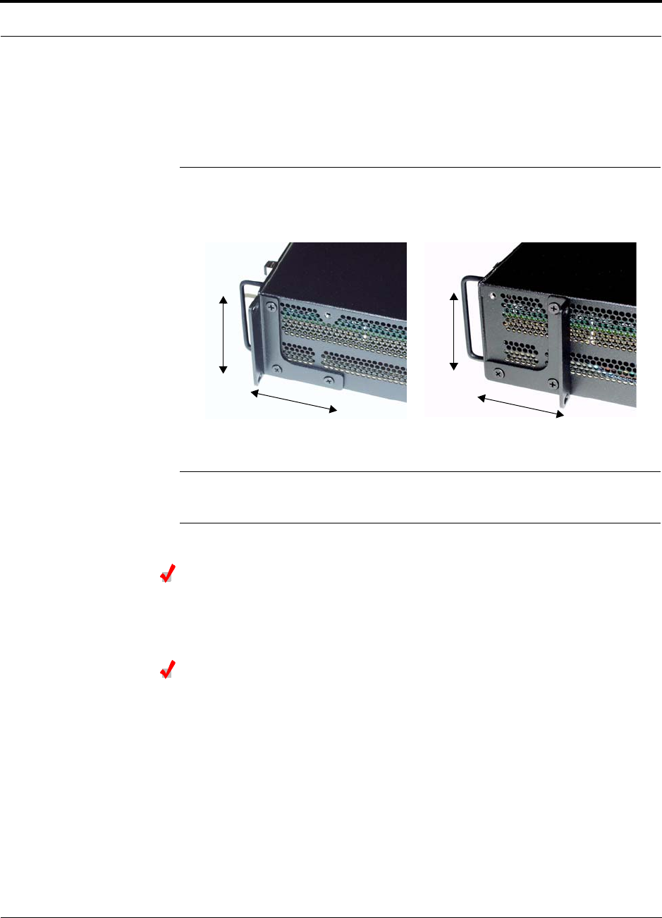
Help Hot Line (U.S. only): 1-800-530-9960 7-19
D-620003-0-20 Rev M CONFIDENTIAL
Unison Component Installation Procedures
3. Reattach each of the rack mounting brackets to the opposite side of the hub from
which it came.
Refer to Figure 7-2 for bracket placement.
Figure 7-2 Mounting Bracket Installation
4. Attach the Expansion Hub to the rack.
NOTE: Leave the dust caps on the fiber ports until you are ready to connect the fiber
optic cables.
Installing an Optional Cable Manager in the Rack
• Using the screws provided, fasten the cable manager to the rack, immediately
above or below the Expansion Hub.
Powering On the Expansion Hub
1. Connect the AC power cord to the Expansion Hub.
2. Plug the power cord into an AC power outlet.
3. Turn on the power to the Expansion Hub and check that all the LED lamps are
functioning properly.
Upon power-up, the LEDs blinks for five seconds as a visual check that they are
functioning. After the five-second test:
• The POWER and UL STATUS LEDs should be green.
– If the uplink fiber is not connected within 90 seconds after the test, the
UL STATUS LED will turn red indicating that there is no communication with
the Main Hub.
Right Rack Mounting Bracket as
installed from the factory.
Left Rack Mounting Bracket installed on
the right side of the hub.
3''
3.5''
3''
3.5''

Unison Component Installation Procedures
7-20 InterReach Unison Installation, Operation, and Reference Manual
CONFIDENTIAL D-620003-0-20 Rev M
• The E-HUB STATUS and DL STATUS LEDs should be red.
• All port LEDs should be off because no RAUs are connected yet.
Connecting the Fiber Cables to the Expansion Hub
Considerations:
• Before connecting the fiber cables, confirm that their optical loss does not exceed
3 dB optical budget. RL is less than -60dB.
• If fiber distribution panels are used, confirm that the total optical loss of fiber
cable, from the Main Hub through distribution panels and patch cords to the
Expansion Hub, does not exceed the optical budget.
• Make sure the fiber cable’s connectors are SC/APC (angle-polished).Using any
other connector type will result in degraded system performance and may damage
the equipment. (You can use an SC/APC pigtail if the fiber cable’s connectors are
not SC/APC, refer to “Fusion Splicing of Fiber and Pigtail” on page 7-33, or
replace the connectors.)
NOTE: Observe all Fiber Port Safety Precautions listed in Section 7.2.3 on page 7-5.
To connect the fiber cables:
The fiber cable is labeled with either 1 or 2, or is color-coded. For proper connection
between the Main Hub ports and the Expansion Hub ports, refer to the numbering or
color-coded connections you recorded when installing the Expansion Hub(s).
If the fiber jumper is labeled with 1 or 2:
1. Connect 1 to DOWNLINK on Expansion Hub.
The DL STATUS LED should turn green as soon as you connect the fiber. If it does
not, there is a downlink problem. Make sure you are connecting the correct cable
to the port.
2. Connect 2 to UPLINK on Expansion Hub.
The UL STATUS LED turns green on the first Main Hub communication. It may
take up to 20 seconds to establish communication.
The Expansion Hub’s E-HUB STATUS LED turns green when the Main Hub sends
it the frequency band command.
If the UL STATUS and E-HUB STATUS LEDs do not turn green/green, check the
Main Hub LEDs. Refer to page 7-16, item 2 in Table 7-5.
If the fiber jumper is color-coded (for example, “blue” or “red”):
1. Connect “blue” to DOWNLINK on Expansion Hub.
The DL STATUS LED should turn green as soon as you connect the fiber. If it does
not, there is a downlink problem. Make sure you are connecting the correct cable
to the port.

Help Hot Line (U.S. only): 1-800-530-9960 7-21
D-620003-0-20 Rev M CONFIDENTIAL
Unison Component Installation Procedures
2. Connect “red” to UPLINK on Expansion Hub.
The UL STATUS LED turns green on the first Main Hub communication. It may
take up to 20 seconds to establish communication.
The Expansion Hub’s E-HUB STATUS LED turns green when the Main Hub sends
it the frequency band command.
If the UL STATUS and E-HUB STATUS LEDs do not turn green/green, check the
Main Hub LEDs. See page 7-16, item 2 in Table 7-5.
Connecting the ScTP Cables
Consideration:
• Verify that the cable has been tested and the test results are recorded.
To test and connect the ScTP cable:
1. Perform cable testing.
Test results are required for the final As-Built Document.
Cable length:
– Minimum: 10 m (33 ft)
– Recommended Maximum: 100 m (328 ft)
– Absolute Maximum: 150 m (492 ft)
If you are using a Cat-5 Extender, the cable length maximum is 170 m (557 feet).
(Refer to Section 7.4.5 on page 7-29.)
2. Label both ends of each cable with which RJ-45 port you’re using.
3. Connect the ScTP cables to any available RJ-45 port on the Expansion Hub.
The LINK and RAU LEDs should be off because the RAU is not connected.
4. Record which cable you are connecting to which port.
This information is required for the As-Built Document.
5. Tie-off cables or use the optional cable manager to avoid damaging the connec-
tors because of cable strain.

Unison Component Installation Procedures
7-22 InterReach Unison Installation, Operation, and Reference Manual
CONFIDENTIAL D-620003-0-20 Rev M
7.4.2.1 Troubleshooting Expansion Hub LEDs During Installation
• All Expansion Hub LINK and E-HUB/RAU LEDs with RAUs connected should indi-
cate Green/Red. This indicates that the RAU is powered on and communication
has been established.
• The Expansion Hub UL STATUS LED should be Green.
Table 7-6 Troubleshooting Expansion Hub LEDs During Installation
During
Installation LED State Action Impact
1. Expansion
Hub power
is On and no
RAUs are
connected
POWER Off Check AC power; make sure the
Expansion Hub power-on switch
is on; replace the Expansion Hub.
The Expansion Hub is not
powering on.
LINK LEDs are on but
didn’t blink through
all states.
Replace the Expansion Hub. The Microcontroller is not
resetting properly; flash
memory corrupted.
RAU
LINK Red Port unusable; replace the Expan-
sion Hub when possible. Current sensor fault; do not
use the port.
RAU Off
UL STATUS Red, after power-up
blink Replace the Expansion Hub. The Expansion Hub laser is
not operational; no uplink
between the Expansion Hub
and Main Hub.
UL STATUS
Red from green after
90 second power-up
blink, the cable was
connected within 90
seconds of power up.
Check the Main Hub LEDs
Refer to page 7-16, item 2 in
Table 7-5.
No communication with
Main Hub.
DL STATUS Red Check the downlink fiber for opti-
cal power; verify that the cables
are connected to correct ports
(that is, uplink/downlink)
Check the Main Hub LEDs. Refer
to page 7-16, item 2 in Table 7-5.
No downlink between the
Expansion Hub and Main
Hub.
2. Expansion
Hub power
is On and
RAUs are
connected
LINK Off Check the Cat-5E/6 cable.
Check the Cat-5 Extender if one is
being used.
Power is not getting to the
RAU.
RAU Off
LINK Red Test the Cat-5E/6 cable. If the
cable tests OK, try another port. If
the second port’s LEDs are
Red/Off, replace the RAU. If the
second RAU doesn’t work;
replace the Expansion Hub.
Check the Cat-5 Extender if one is
being used.
Power levels to RAU are not
correct; communications are
not established.
If the second port works, flag
the first port as unusable;
replace EH when possible.
RAU Off
LINK Green Use AdminManager to determine
the problem. RAU is off-line.
RAU Red
Help Hot Line (U.S. only): 1-800-530-9960 7-23
D-620003-0-20 Rev M CONFIDENTIAL
Unison Component Installation Procedures
7.4.2.2 Installing Expansion Hubs in a Multiple Operator System
Installing Expansion Hubs in a multiple operator system is the same as described in
Section 7.4.2 on page 7-18.
If rack-mounting the Expansion Hubs, we recommend mounting all multiple operator
system hubs in the same rack(s) or location, grouped by frequency or carrier. For
example, group the Expansion Hubs for iDEN together, then the 800 MHz cellular
bands, and so on.
7.4.3 Installing RAUs
CAUTION: Install RAUs in indoor locations only. Do not connect
an antenna that is installed in an outdoor location to an RAU.
Installing RAUs
Mount all RAUs in the locations marked on the floor plans.
Considerations:
•Install iDEN and 800 MHz Cellular RAUs so that their antennas are apart enough
to reduce signal interference between the two bands. Refer to Section , “800 MHz
Isolation Requirements,” on page 7-23 for recommended distance between anten-
nas.
• Attach the RAU securely to a stationary object (that is, wall, pole, ceiling tile).
• For proper ventilation:
• Keep at least 76 mm (3 in.) clearance around the RAU to ensure proper venting.
Do not stack RAUs on top of each other.
• Always mount the RAU with the solid face against the mounting surface.
Installing Passive Antennas
Refer to the manufacturer’s installation instructions to install passive antennas.
Location
Passive antennas are usually installed below the ceiling. If they are installed above
the ceiling, the additional loss due to the ceiling material must be considered when
estimating the antenna coverage area.
800 MHz Isolation Requirements
When deploying any RF system, give special attention to preventing receiver block-
ing or desensitization by out-of-band transmitters. Typically, sharp filters in the
receiver front-end will reduce the interfering transmitters to tolerable levels. In select
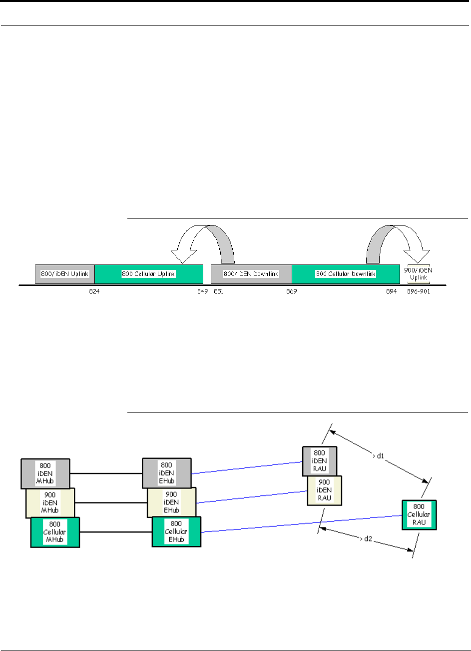
Unison Component Installation Procedures
7-24 InterReach Unison Installation, Operation, and Reference Manual
CONFIDENTIAL D-620003-0-20 Rev M
cases, the interferers may occupy a frequency band that is directly adjacent to the
receiving band and cannot be adequately rejected by filtering. The only recourse in
these situations is to provide sufficient isolation by physically separating the interfer-
ing transmitters and receivers.
iDEN occupies spectrum at both 800 MHz and 900 MHz (Tx:806–825/Rx:851–870
and Tx:896–901/Rx:935–940), while the Cellular A and B carriers share a single 800
MHz block (Tx:869–894/Rx:824–849). The combination of these frequency bands,
800/900 MHz iDEN and 800 MHz Cellular, result in uplink (BTS receive) bands that
are adjacent to downlink (BTS transmit) bands. Figure 7-3 depicts these nearly con-
tiguous bands, with arrows indicating the interfering downlink and receiving uplink
bands.
Figure 7-3 800 MHz Spectrum
Installation of an in-building distributed antenna system (DAS) to provide coverage
for both 800/900 MHz iDEN and 800 MHz Cellular must account for these down-
link-to-uplink interference issues and provide adequate isolation.
ADC offers the following guidelines toward achieving the proper amount of isolation
when deploying ADC Unison DAS products.
Figure 7-4 Guideline for Unison RAU Antenna Placement
800 MHz iDEN Downlink & 800 MHz Cellular Uplink
A 2 MHz frequency gap (851 – 849 MHz) separates the 800 iDEN downlink and 800
Cellular uplink frequency bands. Because of this narrow spacing, 800 iDEN down-
Help Hot Line (U.S. only): 1-800-530-9960 7-25
D-620003-0-20 Rev M CONFIDENTIAL
Unison Component Installation Procedures
link intermodulation products may fall within the 800 Cellular uplink band. In addi-
tion, 800 iDEN downlink signals near the lower edge of the band at 851 MHz may
cause the 800 Cellular uplink automatic level control (ALC) circuitry in the RAU to
engage and thereby reduce uplink gain.
To prevent either of these conditions, use the following guidelines:
• In-band 800 iDEN intermodulation products < -90dBm
• Lower frequency 800 iDEN signals < –30dBm for Unison
Given a typical DAS configuration (4 iDEN carriers, omni-directional antennas, line
of sight), these guidelines translate to an antenna spacing (d1) of 6–9 meters for Uni-
son.
800 MHz Cellular Downlink & 900 MHz iDEN Uplink
A 2 MHz frequency gap (896 – 894 MHz) separates the 800 Cellular downlink and
900 iDEN uplink frequency bands. Because of this narrow spacing, 800 Cellular
downlink intermodulation products may fall within the 900 iDEN uplink band. In
addition, 800 Cellular downlink signals near the upper edge of the band at 894 MHz
may cause the 900 iDEN uplink ALC to engage and thereby reduce uplink gain.
To prevent either of these conditions, use the following guidelines:
• In-band 800 Cellular intermodulation products < -90dBm
• Upper frequency 800 Cellular signals < –30dBm for Unison
Given a typical DAS configuration (6 CDMA carriers for Unison, omni-directional
antennas, line of sight), these guidelines translate to an antenna spacing (d2) of 8-14
meters for Unison.
Connecting the Antenna to the RAU
Connect a passive antenna to the SMA male connector on the RAU using coaxial
cable with the least amount of loss possible.
CAUTION: Firmly hand-tighten the SMA female connector –
DO NOT over-tighten the connector.
Connecting the ScTP Cable
Consideration:
• Verify that the cable has been tested and the test results are recorded.
To connect the ScTP cable:
• Connect the cable to the RJ-45 female port on the RAU.

Unison Component Installation Procedures
7-26 InterReach Unison Installation, Operation, and Reference Manual
CONFIDENTIAL D-620003-0-20 Rev M
Power is supplied by the Expansion Hub. Upon power up, the LEDs blinks for
two seconds as a visual check that they are functioning. After the two-second test:
• The LINK LED should be green indicating that it is receiving power and com-
munications from the Expansion Hub.
• The ALARM LED should be red until the Main Hub issues the band command,
within about 20 seconds, then it should be green.
7.4.3.1 Troubleshooting RAU LEDs During Installation
• The LINK and ALARM LEDs should be green, and remain green for longer than 90
seconds. The ALARM LED will be red if the system band has not been pro-
grammed.
7.4.3.2 Installing RAUs in a Multiple Operator System
When installing both iDEN and Cellular systems in parallel, either as dual-band or
multiple operator systems, you must take special provision to assure that the individ-
ual RAUs do not interfere with each other.
The 800 MHz Cellular and iDEN RAU’s antennas must be separated by 6 to 8
meters (20 to 26 feet) to assure that the iDEN downlink signals do not interfere
with the Cellular uplink signals.
Table 7-7 Troubleshooting RAU LEDs During Installation
During
Installation LED State Action Impact
1. The RAU is con-
nected to the
Expansion Hub,
which is powered
on
LINK Off Check the Cat-5E/6 cable. No power to RAU.
ALARM Off
LINK Green • Check the Cat-5E/6 cable.
• Check Expansion Hub LEDs
Refer to page 7-22, item 2 in
Table 7-6.
• Use AdminManager to determine
the problem.
RAU is off-line.
ALARM Red
LINK Red from
green, after
the cables are
connected for
60 seconds
• Check the Cat-5E/6 cable
• Check the Expansion Hub LEDs
Refer to page 7-22, item 2 in
Table 7-6.
• Use AdminManager to determine
the problem.
No communications
between the RAU and the
Expansion Hub.
ALARM Red

Help Hot Line (U.S. only): 1-800-530-9960 7-27
D-620003-0-20 Rev M CONFIDENTIAL
Unison Component Installation Procedures
7.4.4 Installing a Dual-Band RAU Configuration
7.4.4.1 Using Dual-Band Diplexer
CAUTION: Install RAUs and diplexers in indoor locations only. Do
not connect an antenna that is installed in an outdoor location.
Dual band RAU configuration consists of:
• 1 higher band RAU
• 1 lower band RAU
• 1 Dual-Band Diplexer (PN #DIPX1-1)
• 2 coaxial cables, 3 ft. long (PN #4005-3)
Installing RAUs in a Dual Band System
Use a Dual-Band Diplexer to combine the output of a low-band RAU and a
high-band RAU to a single dual band antenna.
Considerations:
• The Diplexer will have a high loss when it is connected incorrectly. When using it
with the Unison system, incorrect connections may trigger the Antenna Disconnect
alarm.
• When using the Dual-Band Diplexer, the Unison system Antenna Disconnect
alarm can detect if the cable is disconnected or cut between the RAU and the
Diplexer. This alarm, however, cannot detect it if the cable is disconnected or cut
between the Diplexer and the antenna.
Figure 7-5 shows the RAU configuration in a dual band system. It consists of two
RAUs, one for upper band and one for lower band, a diplexer and two 3 ft. coaxial
cables.
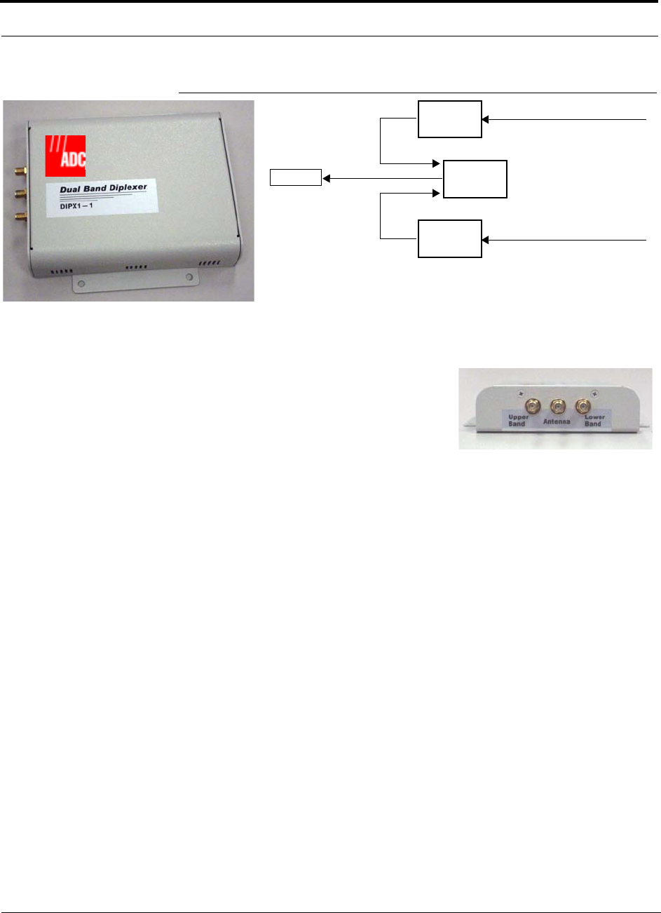
Unison Component Installation Procedures
7-28 InterReach Unison Installation, Operation, and Reference Manual
CONFIDENTIAL D-620003-0-20 Rev M
Figure 7-5 Dual Band RAU Configuration
To connect the RAUs and Dual Band Diplexer for a dual band system:
Unison
RAU
Unison
RAU
Dual Band
Diplexer
Cat-5E/6 from Expansion Hub
Cat-5E/6 from Expansion Hub
Antenna
3 ft. coaxial cable
3 ft. coaxial cable
Dual Band Diplexer
1. Verify that the Unison system is powered on.
2. Attach the Diplexer to a stable surface (that
is, wall, ceiling tile, pole).
Do not mount the Diplexer on top of an RAU.
3. Attach the two RAUs to a stable surface
within 2.5 ft. of the Diplexer (do not stack the RAUs on top of each other).
4. Connect the Cat-5E/6 cable coming from the Unison lower band system (that is,
system band below 1 GHZ) to the correct RAU.
The LINK LED on the RAU should be green.
5. Connect the Cat-5E/6 cable coming from the Unison upper band system (that is,
system band above 1 GHZ) to the correct RAU.
The LINK LED on the RAU should be green.
6. Connect a coaxial cable to the antenna ports on each of the RAUs.
The recommended coaxial cable (PN 4005-3) is 3 ft. long.
7. Connect the coaxial cable coming from the Unison lower band system (that is,
system band below 1 GHZ) to the Diplexer port labeled “LOWER BAND.”
8. Connect the coaxial cable coming from the Unison upper band system (that is,
system band above 1 GHZ) to the Diplexer port labeled “UPPER BAND.”
9. Connect a coaxial cable from the dual band antenna to the Diplexer port labeled
“ANTENNA.”
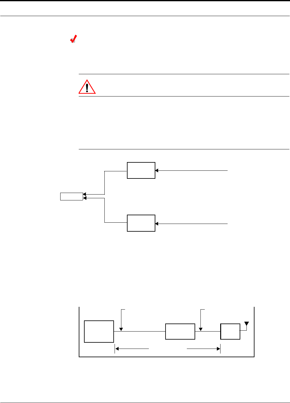
Help Hot Line (U.S. only): 1-800-530-9960 7-29
D-620003-0-20 Rev M CONFIDENTIAL
Unison Component Installation Procedures
Connecting the Antenna to the Dual Band Diplexer
Connect a single passive antenna to the Dual Band Diplexer’s “Antenna” SMA con-
nector using coaxial cable with the least amount of loss possible.
CAUTION:Firmly hand-tighten the SMA female connector –
DO NOT over-tighten the connector.
7.4.4.2 Using Dual-Port Antenna
Connect both RAUs directly to a dual-port, dual-band antenna.
Figure 7-6 Dual-Port Antenna Configuration
7.4.5 Using a Cat-5 Extender
The Cat-5 Extender (PN #UNS-EX170-1)** increases the maximum length of the
Cat-5E/6 ScTP cable run that connects the Expansion Hub to the RAU from 100
meters to 170 meters. The minimum cable length between the Hub and Extender is 90
meters and the minimum length between the Extender and RAU is 20 meters. Beyond
the minimum lengths, an additional 60 meters of cable, maximum of 170 meters total,
can be inserted before or after the Extender.
Table 7-8 shows the minimum and maximum cable lengths that must be met:
Unison
RAU
Unison
RAU
Cat-5E/6 from Expansion Hub
Cat-5E/6 from Expansion Hub
Antenna
3 ft. coaxial cable
3 ft. coaxial cable
Expansion
Hub
Unison
Cat-5E/6 ScTP Cable
90 meters minimum
Unison Cat-5
Extender
Cat-5E/6 ScTP Cable
20 meters minimum
170 meters maximum
RAU
295 feet minimum 65 feet minimum
557 feet maximum
** For Japan, refer to the separate addendum - Japan Specification Document.
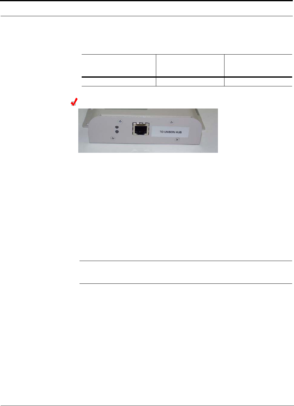
Unison Component Installation Procedures
7-30 InterReach Unison Installation, Operation, and Reference Manual
CONFIDENTIAL D-620003-0-20 Rev M
Table 7-8 Maximum/Minimum Cable Lengths
Installing a Cat-5 Extender
Power is transported from the Unison system to the Cat-5 Extender using the
Cat-5E/6 cable. No power comes from the RAU. Although the bottom LED on the
Cat-5 Extender lights green when the cable is connected to either port, it is only pro-
viding power when it is correctly inserted into the port labeled “TO UNISON HUB.”
(Note that the top LED is disabled and will not light.)
1. Verify that the Unison system is powered on and that the Cat-5E/6 cable is con-
nected into the appropriate port.
2. At the Cat-5 Extender site, plug the Cat-5E/6 cable coming from the Unison sys-
tem into the Extender port labeled “TO UNISON HUB.” The Extender’s bottom
LED should light green if the Expansion Hub is powered on.
3. Connect the Cat-5E/6 cable going to the RAU into the other port, which is labeled
“TO RAU.”
CAUTION:Ensure that the cables are connected to the correct ports. Otherwise, you
may damage the RAU.
If the bottom LED does not light after you have verified that the Cat-5E/6 cable from
the Unison system is plugged into the port called “TO UNISON HUB,” then the Uni-
son system may not be powered on, the Cat-5E/6 cable may be cut/broken, or there is
a problem with the Extender. Verify that the Unison system is connected to AC
power and the power switch is in the ON position.
7.4.6 Configuring the System
Min. Cat-5E/6 Cable Length
from Unison Hub to
Extender
Min. Cat-5E/6 Cable
Length from Extender to
RAU
Max. Cat-5E/6 Cable
Length from Unison Hub
to RAU
90 meters (295 feet) 20 meters (65 feet) 170 meters (557 feet)
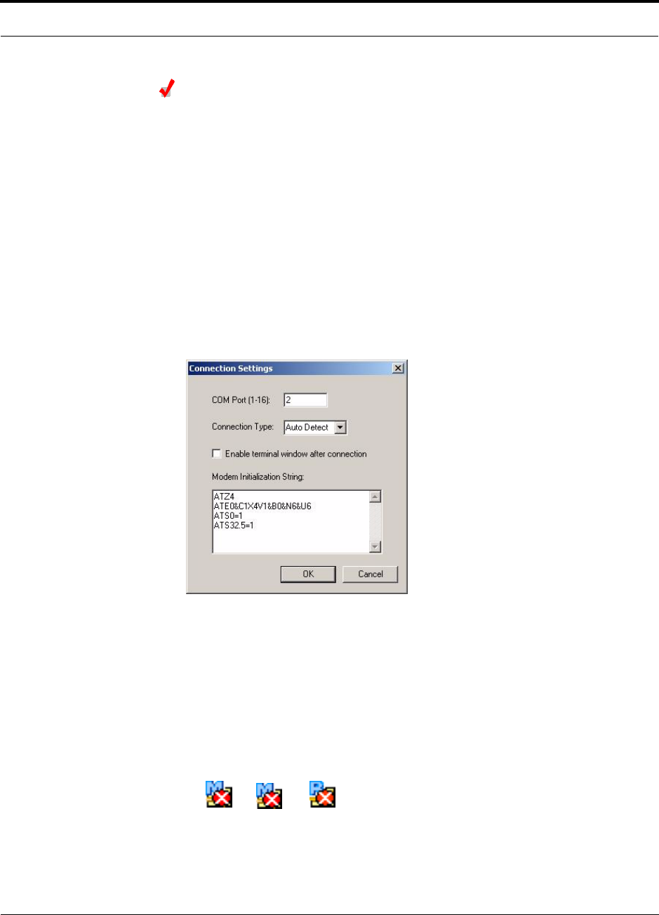
Help Hot Line (U.S. only): 1-800-530-9960 7-31
D-620003-0-20 Rev M CONFIDENTIAL
Unison Component Installation Procedures
Configuring the Installed System
Considerations:
• The AdminManager PC/laptop is connected to the Main Hub.
• The AdminManager software is started.
• All system components are installed and powered on.
To configure an installed system:
1. Turn on the PC and start AdminManager.
The AdminManager main window appears.
2. Disable alarm filtering. Use View, Preferences and select “Enable faults, warn-
ings, and status messages.”
3. Select Settings from the Connection menu item.
The Connection Settings dialog box appears.
4. Enter the COM Port in the text box.
5. Select the Connection Type from the drop-down menu. ADC recommends using
Auto Detect if unsure.
6. Click OK.
7. Press the Enter key to initiate the connection.
When the connection is made, a hierarchical system tree is displayed in the left
pane of the window. The following icons are displayed indicated that the fre-
quency band is not programmed:
If the system tree is not displayed, press F5 key to refresh the tree display.
8. Right-click on the Main Hub icon and select Install/Configure System.
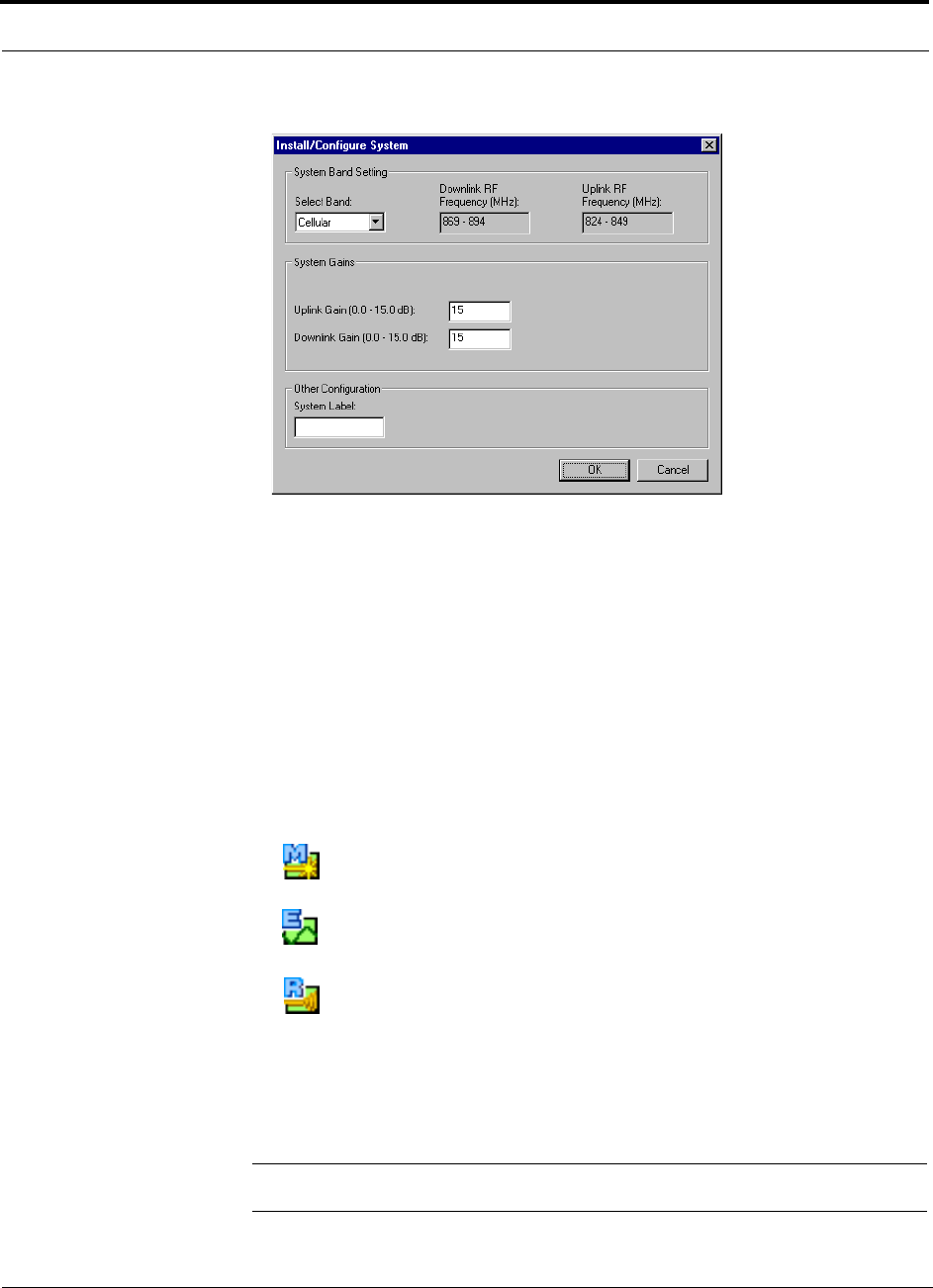
Unison Component Installation Procedures
7-32 InterReach Unison Installation, Operation, and Reference Manual
CONFIDENTIAL D-620003-0-20 Rev M
The System Configuration window appears.
9. Select the operating band from the Select Band pull down menu.
The operating band must match the band of the RAUs that are used in the system.
10. Change the System Gain in the text boxes, if desired.
The default is 0 dB for both the uplink and downlink.
11. Change the System Label, if desired.
The default is “Unison.”
12. Click OK.
During configuration, which can take several minutes for a fully-loaded system
(that is, 32 RAUs), all disconnect status are cleared; the frequency band, gain, and
system label are set; logs are cleared; the system test is performed; and finally the
status tree is refreshed. The icons should be:
Indicating that the band is correctly set.
Indicating that communications are OK.
Indicating that communications are OK.
If there are problems, the icons are different and a message is displayed in the
Messages pane.
The Unison system should now be operational. Using a mobile phone, walk your
site and test the signal strength.
NOTE: Refer to Section 9 for troubleshooting.

Help Hot Line (U.S. only): 1-800-530-9960 7-33
D-620003-0-20 Rev M CONFIDENTIAL
Splicing Fiber Optic Cable
7.5 Splicing Fiber Optic Cable
The fiber cable must have SC/APC connectors for the entire run. If it does not, you
can splice a pigtail, which has SC/APC connectors, to the fiber cable.
ADC offers two pigtails: one for single-mode fiber (PN 4013SCAPC-3) and one for
multi-mode fiber (PN 4012SCAPC-3).
ADC recommends fusion splices because they have the lowest splice loss and return
loss. Mechanical splices have higher losses and higher back reflection than fusion
splices and are not recommended.
7.5.1 Fusion Splices
Using a fusion splicer involves fusing together two butted and cleaved ends of fiber.
The fusion splicer aligns the fibers and maintains alignment during the fusion pro-
cess. Fusion splices have very low loss (typically less than 0.05 dB) and very low
back reflection (return loss). Fusion splices should be organized in a splice tray
designed to store and protect the splices.
Fusion Splicing of Fiber and Pigtail
Before you begin, make sure the fusion splicer is set to the proper mode (that is, sin-
gle- or multi-mode).
To fusion splice the fiber optic cable to the SC/APC pigtail: Option A
1. Secure both the fiber cable and the SC/APC pigtail in a splice tray that is installed
immediately adjacent to the Hub.
2. Prepare the fiber end by cutting back the polyethylene jacket, the kevlar or fiber-
glass strength members, the extruded coating, and the buffer coating in order to
expose the “bare fiber” – cladding plus core.
Ensure that sufficient slack is maintained in order to be able to reach the fusion
splicer.
3. Clean the unclad fiber core using isopropyl alcohol and lint-free wipes.
4. Cleave the unclad fiber to the length prescribed by the fusion splicer’s specifica-
tion sheets.
5. Repeat steps 2 through 4 for the SC/APC pigtail.
6. Pass the splice sleeve onto the fiber strand.
7. Position both fiber ends in the fusion splicer and complete splice in accordance
with the fusion splicer’s operation instructions.
8. Ensure that the estimated loss for the splice as measured by the fusion splicer is
0.10 dB or better.
9. Slide the fusion splicing sleeve over the point of the fusion splice.
10. Place the sleeve and fused fiber into the fusion splicer’s heater.

Splicing Fiber Optic Cable
7-34 InterReach Unison Installation, Operation, and Reference Manual
CONFIDENTIAL D-620003-0-20 Rev M
11. Allow time for the splice sleeve to cure.
12. Return fiber splice to the splice tray, store the sleeve in a splice holder within the
tray, and store excess cable length in accordance with the tray manufacture’s
directions.
After successfully testing the fiber, plug the SC/APC pigtail into the proper opti-
cal port on the Hub.
To fusion splice the fiber optic cable to the SC/APC pigtail: Option B
1. Secure both the fiber cable and the SC/APC pigtail in a splice tray portion of a
fiber distribution panel.
2. Prepare the fiber end by cutting back the polyethylene jacket, the kevlar or fiber-
glass strength members, the extruded coating, and the buffer coating in order to
expose the “bare fiber” – cladding plus core.
Ensure that sufficient slack is maintained in order to be able to reach the fusion
splicer.
3. Clean the unclad fiber core using isopropyl alcohol and lint-free wipes.
4. Cleave the unclad fiber to the length prescribed by the fusion splicer’s specifica-
tion sheets.
5. Repeat steps 2 through 4 for the SC/APC pigtail.
6. Pass the splice sleeve onto the fiber strand.
7. Position both fiber ends in the fusion splicer and complete splice in accordance
with the fusion splicer’s operation instructions.
8. Ensure that the estimated loss for the splice as measured by the fusion splicer is
0.10 dB or better.
9. Slide the fusion splicing sleeve over the point of the fusion splice.
10. Place the sleeve and fused fiber into the fusion splicer’s heater.
11. Allow time for the splice sleeve to cure.
12. Return fiber splice to the splice tray, store the sleeve in a splice holder within the
tray, and store excess cable length in accordance with the tray manufacture’s
directions.
13. After successfully testing the fiber cable, plug the SC/APC pigtail into the back
side of the SC/APC bulkhead in the Fiber Distribution Panel.
Install a SC/APC patch cord between the front side of the SC/APC bulkhead and
the proper optical port on the Hub.
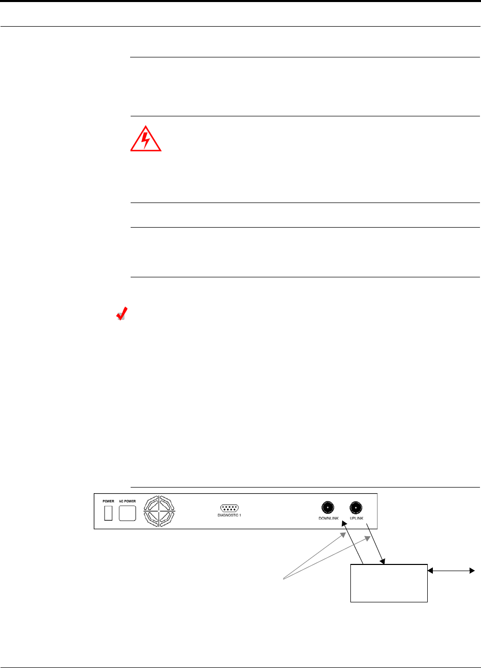
Help Hot Line (U.S. only): 1-800-530-9960 7-35
D-620003-0-20 Rev M CONFIDENTIAL
Interfacing a Main Hub to a Base Station or a Roof-top Antenna
7.6 Interfacing a Main Hub to a Base Station or a
Roof-top Antenna
WARNING: Only ADC personnel or ADC-authorized installation per-
sonnel should connect the Unison Main Hub to a base station or
repeater. Exceeding the maximum input power could cause failure of
the Main Hub (refer to Section 6.1 on page 6-3 for maximum power
specifications). If the maximum composite power is too high, attenua-
tion is required.
NOTE: The UPLINK and DOWNLINK ports cannot handle a DC power feed
from a base station. If DC power is present, a DC block must be used or the
main hub may be damaged.
Connecting a Main Hub to an In-Building Base Station
Connecting a Simplex Base Station to a Main Hub:
1. Connect an N-male to N-male coaxial cable to the transmit simplex connector on
the base station.
2. Connect the other end of the N-male to N-male coaxial cable to the DOWNLINK
connector on the Main Hub.
3. Connect an N-male to N-male coaxial cable to the receive simplex connector on
the base station.
4. Connect the other end of the N-male to N-male coaxial cable to the UPLINK con-
nector on the Main Hub.
Figure 7-7 Simplex Base Station to a Main Hub
N-male to N-male
Coaxial Cable
Base Station
Simplex T1/E1 to
Mobile
Switching
Center
Insert attenuator, if needed
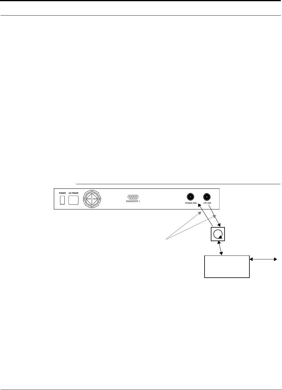
Interfacing a Main Hub to a Base Station or a Roof-top Antenna
7-36 InterReach Unison Installation, Operation, and Reference Manual
CONFIDENTIAL D-620003-0-20 Rev M
Connecting a Duplex Base Station to a Main Hub:
When connecting to a duplex base station, use a circulator between it and the Main
Hub.
You can insert attenuators between the circulator and Main Hub as needed; refer to
Section 6.6.1 on page 6-40 for more information.
1. Connect an N-male to N-male coaxial cable to the duplex connector on the base
station.
2. Connect the other N-male connector to a circulator.
3. Connect an N-male to N-male coaxial cable to the DOWNLINK connector on the
Main Hub.
4. Connect the other end of the N-male coaxial cable to the transmit connector on the
circulator.
5. Connect an N-male to N-male coaxial cable to the UPLINK connector on the Main
Hub.
6. Connect the other end of the N-male coaxial cable to the receive connector on the
circulator.
Figure 7-8 Duplex Base Station to a Main Hub
N-male to N-male
Coaxial Cable
Base Station
Duplex T1/E1 to
Mobile
Switching
Center
Insert attenuator, if needed N-male to N-male
Coaxial Cable
Circulator
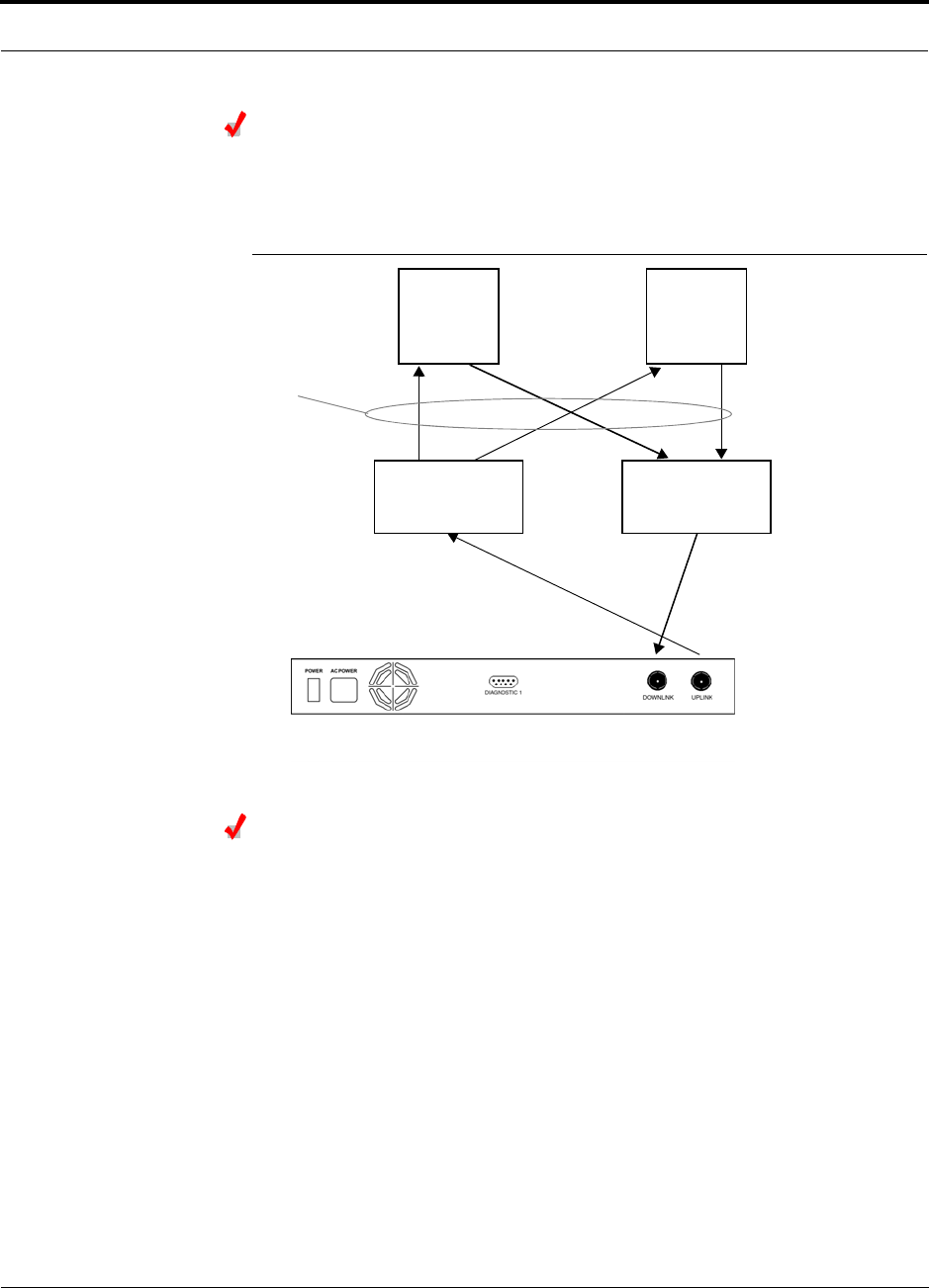
Help Hot Line (U.S. only): 1-800-530-9960 7-37
D-620003-0-20 Rev M CONFIDENTIAL
Interfacing a Main Hub to a Base Station or a Roof-top Antenna
Connecting a Main Hub to Multiple Base Stations
You can use power combiner/splitters to connect a Main Hub to multiple base sta-
tions, as shown in Figure 7-9.
Figure 7-9 Connecting a Main Hub to Multiple Base Stations
Connecting a Main Hub to a Roof-top Antenna
ADC recommends that you use a lightning arrestor or surge protector in a roof-top
antenna configuration. Insert the lightning arrestor or surge protector between the
roof-top antenna and the repeater that is connected to the Main Hub.
1. Connect an N-male to N-male coaxial cable to the roof-top antenna.
2. Connect the other end of the N-male to N-male coaxial cable to the grounded
surge suppressor.
3. Connect an N-male to N-male coaxial cable to the grounded surge suppressor.
4. Connect the other end of the N-male to N-male coaxial cable to the repeater.
5. Connect an N-male to N-male coaxial cable to the repeater.
6. Connect the other end of the N-male to N-male coaxial cable to the circulator
1connector.
7. Connect an N-male to N-male coaxial cable to the circulator 2connector.
8. Connect the other end of the N-male to N-male coaxial cable to the DOWNLINK
connector on the Main Hub.
N-male to N-male
Coaxial Jumper Cables
N-male to N-male
Coaxial Jumper Cable
to Repeater or
Base Station
between Combiner/Splitter and
N-male to N-male
Coaxial Jumper Cables
between Combiner/Splitter and
Main Hub’s Uplink Port Main Hub’s Downlink Port
2 x 1 Power
Combiner/Splitter 2 x 1 Power
Combiner/Splitter
BTS 1
UL DL
BTS 2
UL DL
Insert attenuators, if needed
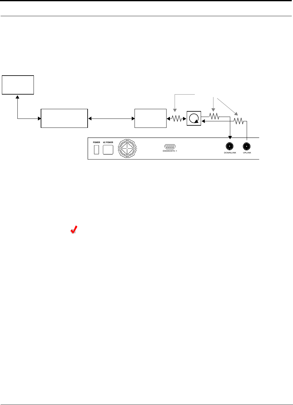
Interfacing a Main Hub to a Base Station or a Roof-top Antenna
7-38 InterReach Unison Installation, Operation, and Reference Manual
CONFIDENTIAL D-620003-0-20 Rev M
Attenuation may be required to achieve the desired RF output at the RAU.
9. Connect an N-male to N-male coaxial cable to the circulator 3connector.
10. Connect the other end of the N-male to N-male coaxial cable to the UPLINK con-
nector on the Main Hub.
7.6.1 Connecting Multiple Main Hubs
You can use power combiner/splitters as splitters to connect multiple Main Hubs in
order to increase the total number of RAUs in a system. You can also use power com-
biner/splitters to combine base station channels in order to increase the number of RF
carriers the system transports.
Connecting Multiple Main Hubs to a Simplex Repeater
or Base Station
Considerations:
• 2 hybrid power combiner/splitters; one for uplink and one for downlink (2x1 for
two Main Hubs, 3x1 for three, 4x1 for four, etc.)
• 1 N-male to N-male coaxial jumper cable between each power combiner/splitter
and the base station
• 2 N-male to N-male coaxial jumper cables between each power combiner/splitter
and each Main Hub
Procedure:
1. Connect the power combiner/splitters to the repeater or base station using N-male
to N-male coaxial jumper cables:
a. From the first power combiner/splitter to the repeater or base station
b. From the second power combiner/splitter to the repeater or base station
2. Connect the power combiner/splitters to the Main Hubs:
a. From the first Main Hub’s UPLINK port to the first power combiner/splitter
Roof-top
Antenna
Grounded
Surge Suppressor Repeater
N-male to N-male
Coaxial Cables
N-male to N-male
Coaxial Cable
N-male to N-male
Coaxial Cable Circulator
Attenuator (optional)
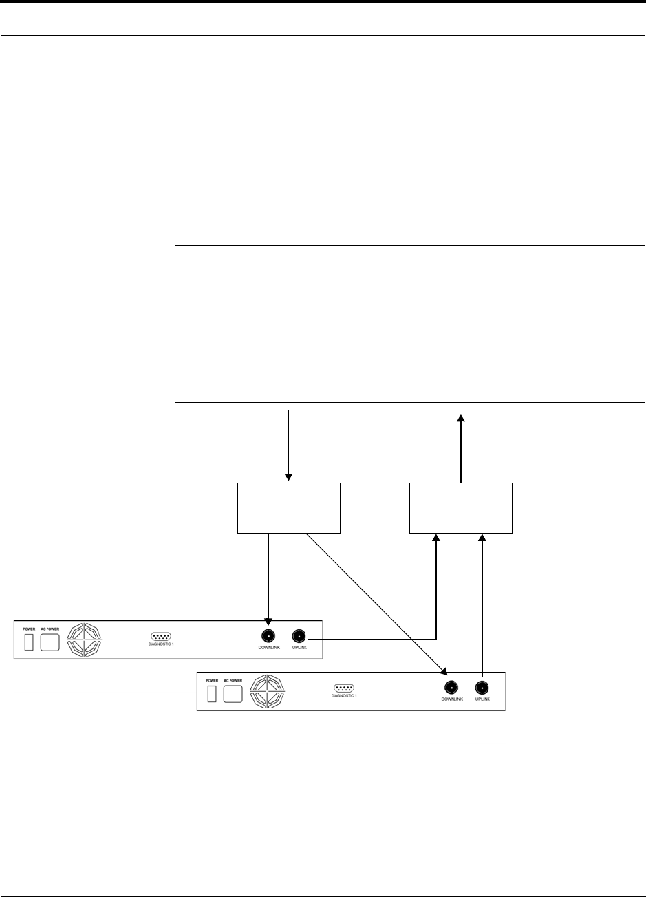
Help Hot Line (U.S. only): 1-800-530-9960 7-39
D-620003-0-20 Rev M CONFIDENTIAL
Interfacing a Main Hub to a Base Station or a Roof-top Antenna
b. From the first Main Hub’s DOWNLINK port to the second power com-
biner/splitter
c. From the second Main Hub’s UPLINK port to the first power combiner/splitter
d. From the second Main Hub’s DOWNLINK port to the second power com-
biner/splitter
3. Check Main Hub LEDs.
After connecting and powering on the Main Hub, check all LEDs to ensure that
the system is operating properly.
NOTE: Use a 50 ohm terminator on any unused power combiner/splitter ports.
Figure 7-10 shows connecting two Main Hubs to a simplex repeater or base station.
Connecting two Main Hubs increases the total number of supportable RAUs from 32
to 64. Two Main Hubs support up to 8 Expansion Hubs which in turn support up to 64
RAUs.
Figure 7-10 Connecting Two Main Hubs to a Simplex Repeater or Base Station
N-male to N-male
Coaxial Jumper Cables
N-male to N-male
Coaxial Jumper Cable
to Repeater or
Base Station
2 x 1 Power
Combiner/Splitter
N-male to N-male
Coaxial Jumper Cable
to Repeater or
Base Station
between Combiner/Splitter and N-male to N-male
Coaxial Jumper Cables
between Combiner/Splitter and
Main Hub’s Downlink Port
Main Hub’s Uplink Port
2 x 1 Power
Combiner/Splitter

Interfacing a Main Hub to a Base Station or a Roof-top Antenna
7-40 InterReach Unison Installation, Operation, and Reference Manual
CONFIDENTIAL D-620003-0-20 Rev M
Connecting Multiple Main Hubs to a Duplex Repeater
or Base Station
Considerations:
• 2 hybrid power combiner/splitters; one for uplink and one for downlink (2x1 for
two Main Hubs, 3x1 for three, 4x1 for four, and so on.)
• 2 N-male to N-male coaxial jumper cables to connect each Main Hub to the power
combiner/splitters
• 1 circulator
• 1 N-male to N-male coaxial jumper cable between each circulator and the repeater
or base station
• 1 N-male to N-male coaxial jumper cable1 between each circulator and power
combiner/splitter
Procedure:
1. Connect the Circulator to the power combiner/splitters and to the repeater or base
station using one N-male to N-male coaxial jumper cable.
2. Connect each power combiner/splitter to the circulator using one N-male to
N-male coaxial jumper cable.
3. Connect the power combiner/splitter to the Main Hubs:
a. From the first Main Hub’s UPLINK port to the first power combiner/splitter
b. From the first Main Hub’s DOWNLINK port to the second power com-
biner/splitter
c. From the second Main Hub’s UPLINK port to the first power combiner/splitter
d. From the second Main Hub’s DOWNLINK port to the second power com-
biner/splitter
4. Check Main Hub LEDs.
After connecting and powering on the Main Hub, check all LEDs to ensure that
the system is operating properly.
NOTE: Use a 50 ohm terminator on any unused power combiner/splitter ports.
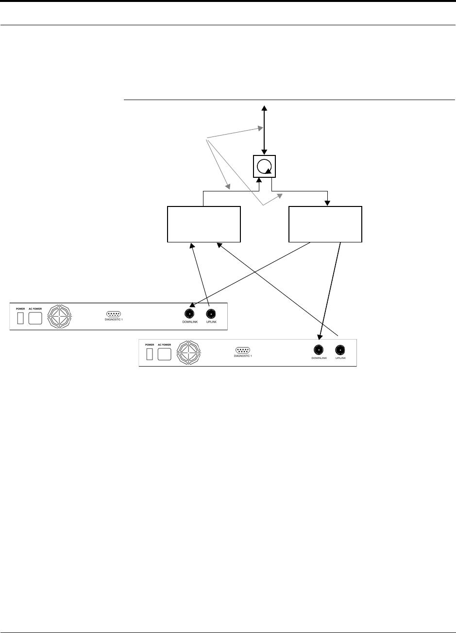
Help Hot Line (U.S. only): 1-800-530-9960 7-41
D-620003-0-20 Rev M CONFIDENTIAL
Interfacing a Main Hub to a Base Station or a Roof-top Antenna
To connect two Main Hubs to a duplex repeater or base station, use one circulator and
one more coaxial jumper cable, as shown in Figure 7-11.
Figure 7-11 Connecting Two Main Hubs to a Duplex Repeater or Base Station
2 x 1 Power
Combiner/Splitter
N-male to N-male
Coaxial Jumper Cable
N-male to N-male
Coaxial Jumper Cables
2 x 1 Power
Combiner/Splitter
N-male to N-male
Coaxial Jumper Cable
Circulator
N-male to N-male
Coaxial Jumper Cable
to Repeater or
Base Station
between Combiner/Splitter and N-male to N-male
Coaxial Jumper Cables
between Combiner/Splitter and
Main Hub’s Downlink Port
Main Hub’s Uplink Port
Insert attenuator, if needed

Connecting Contact Alarms to a Unison System
7-42 InterReach Unison Installation, Operation, and Reference Manual
CONFIDENTIAL D-620003-0-20 Rev M
7.7 Connecting Contact Alarms to a Unison System
The Unison Main Hub can generate (source) two contact alarms as well as sense an
external contact alarm.
• Alarm Source (refer to Section 7.7.1 on page 7-43)
The Main Hub has two alarm contacts, fault (major) and warning (minor). These
contact are normally-closed (NC) and will open when an internal alarm is detected.
NOTE: The contact can be changed to normally-open (NO) with Admin-
Manager. This is not recommended as no alarm would be sent if power to
the Main Hub fails.
• Fault is activated when any faults or disconnects are detected.
• Warning is activated when any warning conditions are detected except lockout
or when the end-to-end system test is not valid.
• Alarm Sense (refer to Section 7.7.2 on page 7-46)
The Main Hub can monitor an external alarm contact. The port can be configured
for normally-open (NO) or normally-closed (NC) contacts. The interface expects a
set of floating contacts, and an external voltage source is not required for this inter-
face. Use AdminManager or OpsConsole to monitor the port status.
Table 7-9 lists the alarm types, equipment that Unison is connected to, cable(s) used,
and the faults (major and/or minor) that are detected.
Table 7-9 Alarm Types
NOTE: The 5-port Alarm Daisy-Chain cable is for normally closed (NC)
contacts.
Alarm
Type Unison
connected to Cable(s) Used Alarms Detected
Source FlexWave
Focus 5-port Alarm Daisy-Chain Cable Faults
Source BTS 5-port Alarm Daisy-Chain Cable Faults and Warnings
In addition, a custom daisy-chain cable-to-BTS interface
cable is required. Make this interface cable to the desired
length and with the appropriate pin placement.
Sense LGCell 5-port Alarm Daisy-Chain Cable
and the Alarm Sense Adapter
Cable
Faults
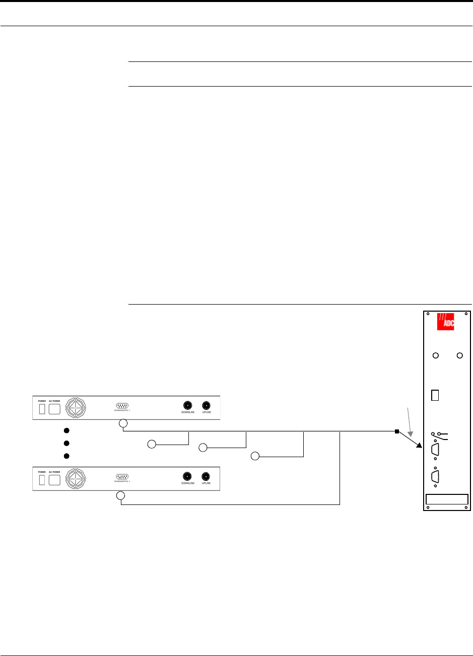
Help Hot Line (U.S. only): 1-800-530-9960 7-43
D-620003-0-20 Rev M CONFIDENTIAL
Connecting Contact Alarms to a Unison System
NOTE: LGCell and FlexWave Focus support only faults (major alarms).
Do not mix LGCell and Unison Main Hubs in the same daisy-chain. You can
daisy-chain multiple LGCell Main Hubs together and use the Alarm Sense Adapter
Cable to connect the chain to a Unison Main Hub, which will act as an alarm sensor.
7.7.1 Alarm Source
Unison always acts an alarm source, no matter what type of equipment you are con-
necting to. Refer to Section 7.7.2 on page 7-46 if you want Unison to sense LGCell
contact closures or other external alarms.
Using FlexWave Focus to Monitor Unison
When you connect FlexWave Focus to Unison, the Unison Main Hub is the output of
the alarms (alarm source) and Focus is the input (alarm sense), as shown in the fol-
lowing figure. Focus supports only faults (major alarms).
Figure 7-12 Connecting FlexWave to Unison
Unison Main Hub
RF OUT
DOWNLINK RF IN
UPLINK
FIBER
UPLINK
DOWNLINK
ALARM
RS-232C
FlexWave
Focus
RFM
Alarm
Sense
Alarm
Source
Alarm
Source
5-port Alarm Daisy-Chain Cable
9-pin Adapter
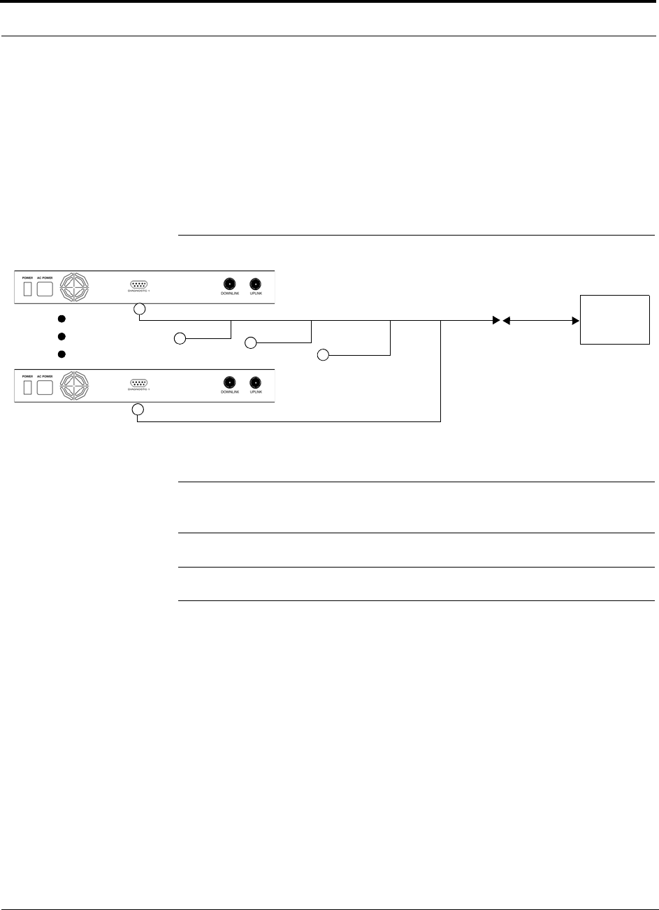
Connecting Contact Alarms to a Unison System
7-44 InterReach Unison Installation, Operation, and Reference Manual
CONFIDENTIAL D-620003-0-20 Rev M
Using a Base Station to Monitor Unison
When you connect a BTS to Unison, the Unison Main Hub is the output of the alarms
(alarm source) and the BTS is the input (alarm sense), as shown in Figure 7-13. An
interface cable is required between the daisy-chain cable and the BTS. Because BTS
alarm interface pinouts and Unison-to-BTS distances vary, this cable often is custom
and wired on-site. Refer to “Main Hub Rear Panel Connectors” on page 3-8 for
Alarm Contact details (Normally Closed).
Figure 7-13 Using a BTS to Monitor Unison
NOTE: For normally open contacts, the fault and warning contacts need to
be wired in parallel with other Main Hubs.
NOTE: ADC does not recommend using normally open contacts.
Unison Main Hub
Alarm
Sense
Alarm
Source
Alarm
Source
BTS
5-port Alarm Daisy-Chain Cable
Interface
Cable
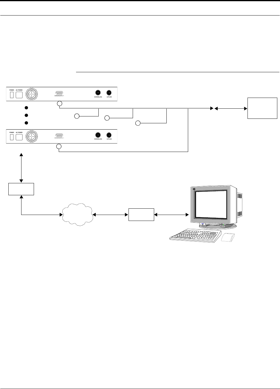
Help Hot Line (U.S. only): 1-800-530-9960 7-45
D-620003-0-20 Rev M CONFIDENTIAL
Connecting Contact Alarms to a Unison System
Using a Base Station and OpsConsole to Monitor Unison
In order to take full advantage of Unison’s OA&M capabilities use ADC OpsConsole
software in addition to a BTS to monitor the system, as shown in Figure 7-14.
Figure 7-14 Using a BTS and OpsConsole to Monitor Unison
Unison Main Hub
Alarm
Sense
Alarm
Source
Alarm
Source
BTS
Interface
Cable
Modem
Straight-through modem cable connected
to Main Hub’s front panel serial port
PSTN Modem
PC running
OpsConsole
Software
5-port Alarm Daisy-Chain Cable
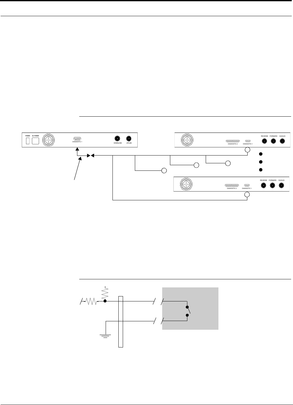
Connecting Contact Alarms to a Unison System
7-46 InterReach Unison Installation, Operation, and Reference Manual
CONFIDENTIAL D-620003-0-20 Rev M
7.7.2 Alarm Sense
Use AdminManager to enable the Unison system for “alarm sense” when connecting
to the contact closure of LGCell Main Hubs or other external alarms (refer to Set
Contact Sense Properties in the AdminManager User Manual).
Using Unison to Monitor LGCells
When you connect LGCell to Unison, the Unison Main Hub is the input of the alarms
(alarm sense) and the LGCell is the output (alarm source), as shown in Figure 7-15.
Figure 7-15 Connecting LGCell to Unison
LGCell supports only faults (major alarms). You must use the Alarm Sense Adapter
Cable (refer to page 7-50) to interface the daisy-chain cable to Unison. The adapter
cable is required because it translates the LGCell fault pinout to the sense input pins
on the Unison Main Hub.
Figure 7-16 Alarm Sense Contacts
Up to 5 LGCell Main HubsUnison Main Hub
Alarm
Sense Alarm
Source
Alarm
Source
Alarm Sense
Adapter Cable
5-port Alarm Daisy-Chain Cable
8
1
Diagnostic I
External
Equipment
Contacts
+5V

Help Hot Line (U.S. only): 1-800-530-9960 7-47
D-620003-0-20 Rev M CONFIDENTIAL
Connecting Contact Alarms to a Unison System
7.7.2.1 Expansion Hub Alarm Sense (UNS-EH-2 only)
The Expansion Hub can sense three external contact closure alarms. These contact
closure inputs were designed for monitoring an Uninterruptible Power Supply (UPS),
but could monitor any external event that provides the proper input level.
These contact closure inputs are user programmable for enable/disable and normally
open/normally closed definition. The factory default is disabled/normally closed for
all three contacts. Use AdminManager to enable and set the appropriate NO/NC state.
If a contact event alarm is detected, the Expansion Hub reports the alarm condition to
the Main Hub as a warning condition. The Expansion Hub front panel LEDs do not
indicate a contact event alarm. Use AdminManager or OpsConsole to determine the
exact alarm event.
The expansion Hub supplies 5V. If the contact is open at the external device, the
Micro reads 5V. When the contact is closed at the external device-the micro reads 0V
or Ground.
Table 7-10 Pin Connections
Table 7-11 Input Electrical Characteristics
DB9 Pin # Connection Signal Name
1N/C N/A
2 +5V through a 10K Ohm resistor. Input to
micro controller ALARM3
3 +5V through a 10K Ohm resistor. Input to
micro controller ALARM1
4 GND N/A
5 +5V through a 10K Ohm resistor. Input to
micro controller ALARM2
6N/C N/A
7N/C N/A
8 GND N/A
9 GND N/A
Parameter Description Specification
Rmin Loop resistance for “OFF” condition > 20k Ohm
Rmax Loop resistance for “ON” condition < 2k Ohm
T on Max Max Turn-on Time 5 Second
T off Max Max Turn-Off Time 5 Second

Connecting Contact Alarms to a Unison System
7-48 InterReach Unison Installation, Operation, and Reference Manual
CONFIDENTIAL D-620003-0-20 Rev M
• The micro controller sees a high or 5V for an open condition. The loop resistance
must be greater then 20K Ohm to guarantee the micro sees 3.5V or greater.
• The micro controller sees low or 0V for a closed condition. The loop resistance
must be greater than 2K Ohm to guarantee the micro sees 1V or less.
• You may have to determine a time on and off for the connection so that the alarm
is not intermittent.
• Firmware has a five second hysteresis to ensure the micro does not capture inter-
mittent contact closures.
Table 7-12 Output Electrical Characteristics
I max is 5V/10K = 500uA. +/- uA due to R and V tolerances.
Vmax is 5V+5% from power supply spec.
Parameter Description Specification
I Max Continuous Load Current 550uA
V Max DC volts out 5 V + 5%
T on Max Max Turn-on Time 5 Seconds
T off Max Max Turn-Off Time 5 Seconds
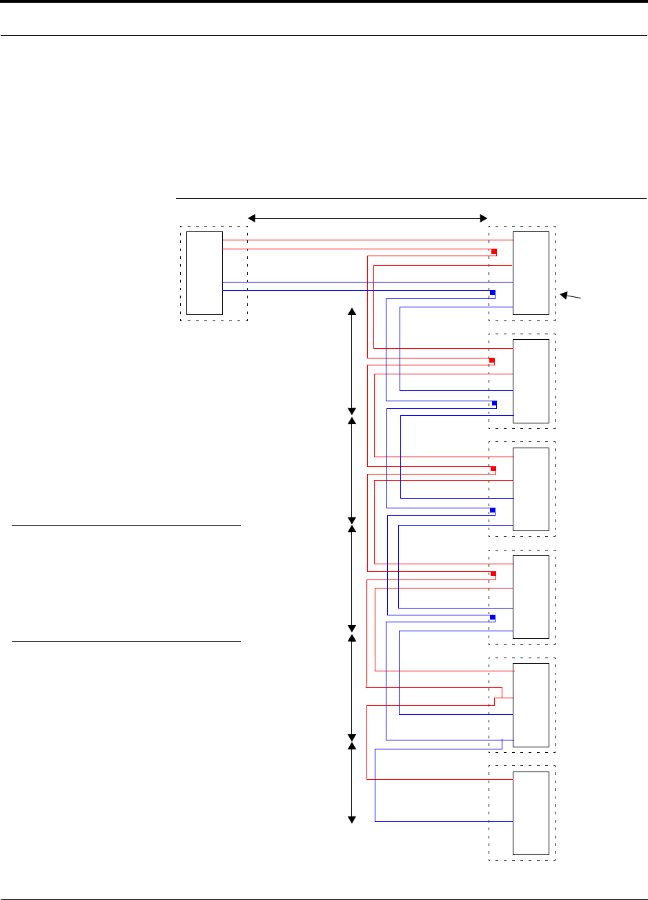
Help Hot Line (U.S. only): 1-800-530-9960 7-49
D-620003-0-20 Rev M CONFIDENTIAL
Connecting Contact Alarms to a Unison System
7.7.3 Alarm Cables
5-port Alarm Daisy-Chain Cable
Figure 7-17 shows the 5-port Alarm Daisy-Chain Cable (PN 4024-3), which supports
fault and warning conditions (that is, major and minor alarms).
Figure 7-17 5-port Alarm Daisy-Chain Cable
DB-9 female to
Base Station,
FlexWave Focus,
or
J1
Female J2
Male
J3
Male
J4
Male
J5
Male
J6
Male
J7
Female
Ter minator
Splice
Splice
Splice
Splice
Splice
Splice
Splice
Splice
7
9
4
5
7
9
4
5
7
9
4
5
7
9
4
5
7
9
4
5
7
4
1.2 meters (4 feet)
.5 meter
(1.5 feet)
DB-9 male to
Unison, FlexWave
Focus, or LGCell
Alarm Port
DB-9 male to
Unison, FlexWave
Focus, or LGCell
Alarm Port
DB-9 male to
Unison, FlexWave
Focus, or LGCell
Alarm Port
DB-9 male to
Unison, FlexWave
Focus, or LGCell
Alarm Port
Option 1: DB-9 to
Unison, FlexWave
Focus, or LGCell
Alarm Port.
J7 not used
Option 2: Use J2-J5
for alarm ports. J6 is used
to connect to an additional
Alarm Daisy-Chain Cable.
J7 is not used.
Option 3: Connect
fewer than 5 ports and
terminate the daisy chain
by connecting J7 to the
lowest unused port.
Connector
Hood
.5 meter
(1.5 feet)
.5 meter
(1.5 feet)
.5 meter
(1.5 feet)
.25 meter
(.75 feet)
the Alarm Sense
Adapter Cable when
connecting LGCell
NOTE: Do not daisy-chain Unison
Main Hubs with LGCell or FlexWave
if you want both faults and warnings
from Unison. Only faults are reported
if you combine Unison with LGCell or
FlexWave in the same daisy chain.
to Unison
7
9
4
5
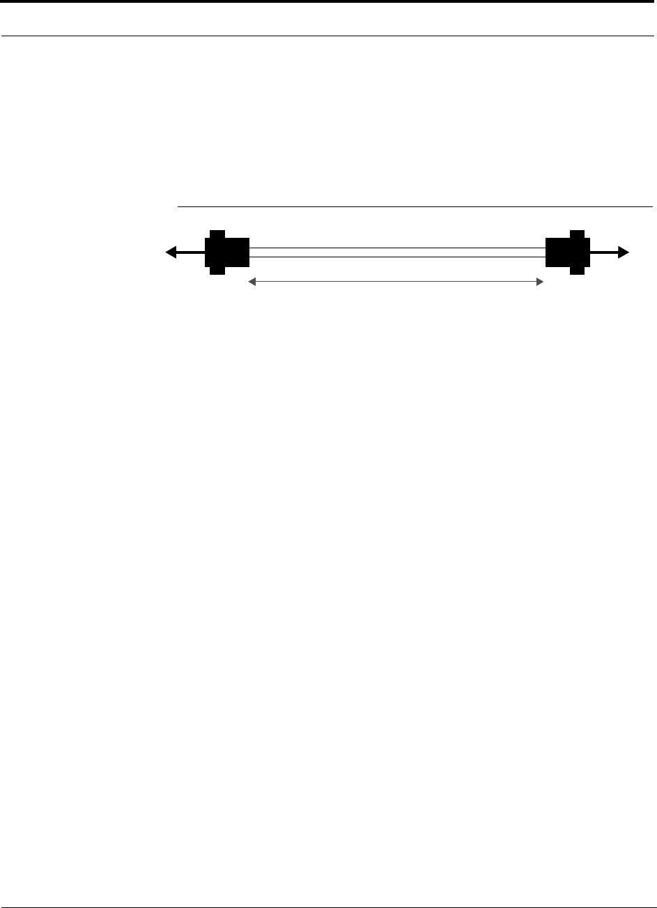
Connecting Contact Alarms to a Unison System
7-50 InterReach Unison Installation, Operation, and Reference Manual
CONFIDENTIAL D-620003-0-20 Rev M
Alarm Sense Adapter Cable
The alarm sense adapter cable (PN 4025-1) translates the LGCell fault pinout to the
sense input pins on the Unison Main Hub. You must use this adapter cable, as illus-
trated in Figure 7-18, with the 5-port Alarm Daisy-Chain Cable when connecting
LGCell to Unison.
Figure 7-18 Alarm Sense Adapter Cable
J8
1
8
J9
7
9
To Unison To Daisy-Chain Cable
3 feet
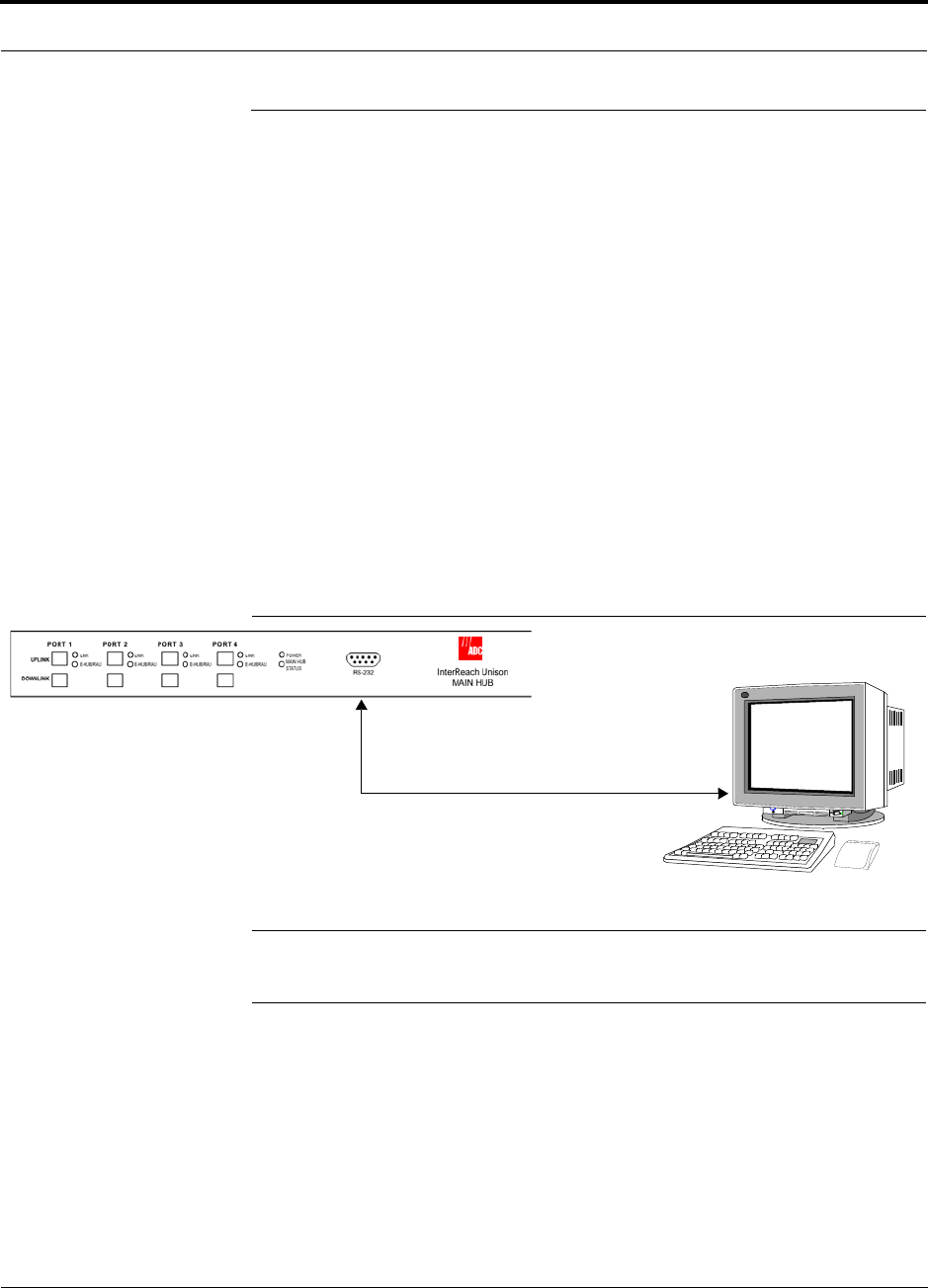
Help Hot Line (U.S. only): 1-800-530-9960 7-51
D-620003-0-20 Rev M CONFIDENTIAL
Alarm Monitoring Connectivity Options
7.8 Alarm Monitoring Connectivity Options
The following connectivity options are described here:
• Section 7.8.1 Direct Connection . . . . . . . . . . . . . . . . . . . . . . . . . . . . . . . . . . . 7-51
• Section 7.8.2 Modem Connection . . . . . . . . . . . . . . . . . . . . . . . . . . . . . . . . . . 7-52
• Section 7.8.3 RS-232 Port Expander Connection . . . . . . . . . . . . . . . . . . . . . . 7-53
• Section 7.8.4 POTS Line Sharing Switch Connection . . . . . . . . . . . . . . . . . . 7-54
• Section 7.8.5 Ethernet and ENET/RS-232 Serial Hub Connection . . . . . . . . 7-55
• Section 7.8.6 Network Interface Unit (NIU) . . . . . . . . . . . . . . . . . . . . . . . . . . 7-56
Note that the only accessory that is available through ADC is the DB-9 to DB-9 null
modem cable, which is provided with AdminManager.
7.8.1 Direct Connection
In this configuration, the AdminManager or OpsConsole PC connects directly to the
RS-232 serial port on the Main Hub’s front panel using a null modem cable.
Figure 7-19 OA&M Direct Connection
NOTE: The null modem cable must support full hardware handshaking.
Refer to Appendix A.5 on page A-4 for cable wiring information.
PC running
or OpsConsole
Software
Null Modem Cable
AdminManager
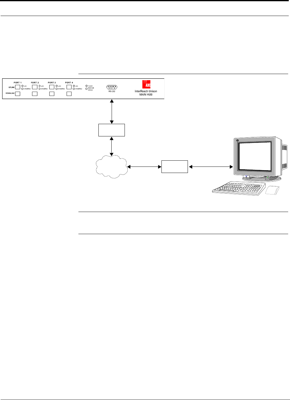
Alarm Monitoring Connectivity Options
7-52 InterReach Unison Installation, Operation, and Reference Manual
CONFIDENTIAL D-620003-0-20 Rev M
7.8.2 Modem Connection
In this configuration, the PC and the Main Hub connect to modems and communicate
using a standard dial-up telephone connection.
Figure 7-20 OA&M Modem Connection
NOTE: Refer to Appendix A.4 on page A-3 for the modem cable wiring informa-
tion.
Modem
Straight-through modem cable
PSTN Modem
PC running
or OpsConsole
Software
AdminManager
Straight-through
modem cable
External Modem
only with OpsConsole
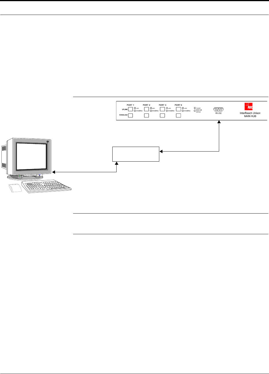
Help Hot Line (U.S. only): 1-800-530-9960 7-53
D-620003-0-20 Rev M CONFIDENTIAL
Alarm Monitoring Connectivity Options
7.8.3 RS-232 Port Expander Connection
In this configuration a port expander is used to allow the connection of multiple
devices to a single PC serial port. Testing was performed with an Equinox SST-16P
Multiport Board. A DB-25 male to DB-9 female modem cable must be made to con-
nect the connector panel to the Main Hub (refer to Appendix A.6 on page A-5). Or,
you can use a DB-25 male/DB-9 male adapter with a DB-9 female to DB-9 female
null modem cable.
Figure 7-21 OA&M Connection using an RS-232 Port Expander
NOTE: Refer to Appendix A.6 on page A-5 for the modem cable wiring informa-
tion.
RS-232 Port Expander
Host Cable
Serial Expansion Card to Connector Panel
Connector Panel
DB-25 male to DB-9 female
Modem Cable
PC running
or OpsConsole
Software
AdminManager
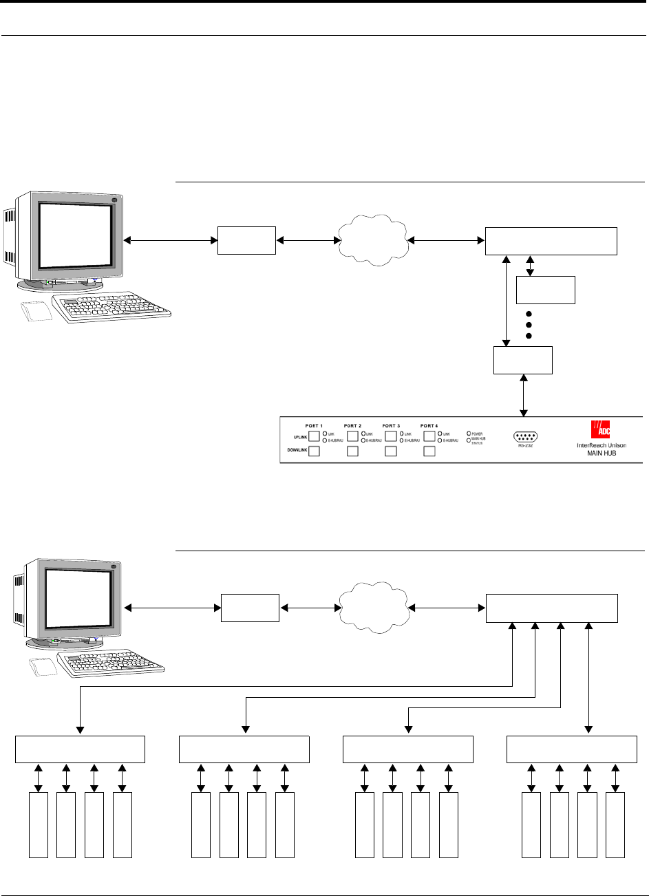
Alarm Monitoring Connectivity Options
7-54 InterReach Unison Installation, Operation, and Reference Manual
CONFIDENTIAL D-620003-0-20 Rev M
7.8.4 POTS Line Sharing Switch Connection
Using a line sharing switch you can connect up to four modems to a single telephone
line. Testing was performed with a Teltone Line Sharing Switch, model number
M-394-B-01.
Figure 7-22 OA&M Connection using a POTS Line Sharing Switch
Up to 16 modems can be monitored using a single telephone line by cascading line
sharing switches, as shown in Figure 7-23.
Figure 7-23 Cascading Line Sharing Switches
Modem
PSTN
Line Sharing Switch
Up to 4 modems
per Switch
Modem
Modem
Straight-through
modem cable
PC running
or OpsConsole
Software
AdminManager Straight-through
modem cable
External Modem
only with OpsConsole
Modem
PSTN
Line Sharing Switch
Line Sharing Switch Line Sharing Switch Line Sharing Switch Line Sharing Switch
M
o
d
e
m
M
o
d
e
m
M
o
d
e
m
M
o
d
e
m
M
o
d
e
m
M
o
d
e
m
M
o
d
e
m
M
o
d
e
m
M
o
d
e
m
M
o
d
e
m
M
o
d
e
m
M
o
d
e
m
M
o
d
e
m
M
o
d
e
m
M
o
d
e
m
M
o
d
e
m
PC running
or OpsConsole
Software
AdminManager
Straight-through
modem cable
Straight-
through
modem
cables
External Modem
only with OpsConsole
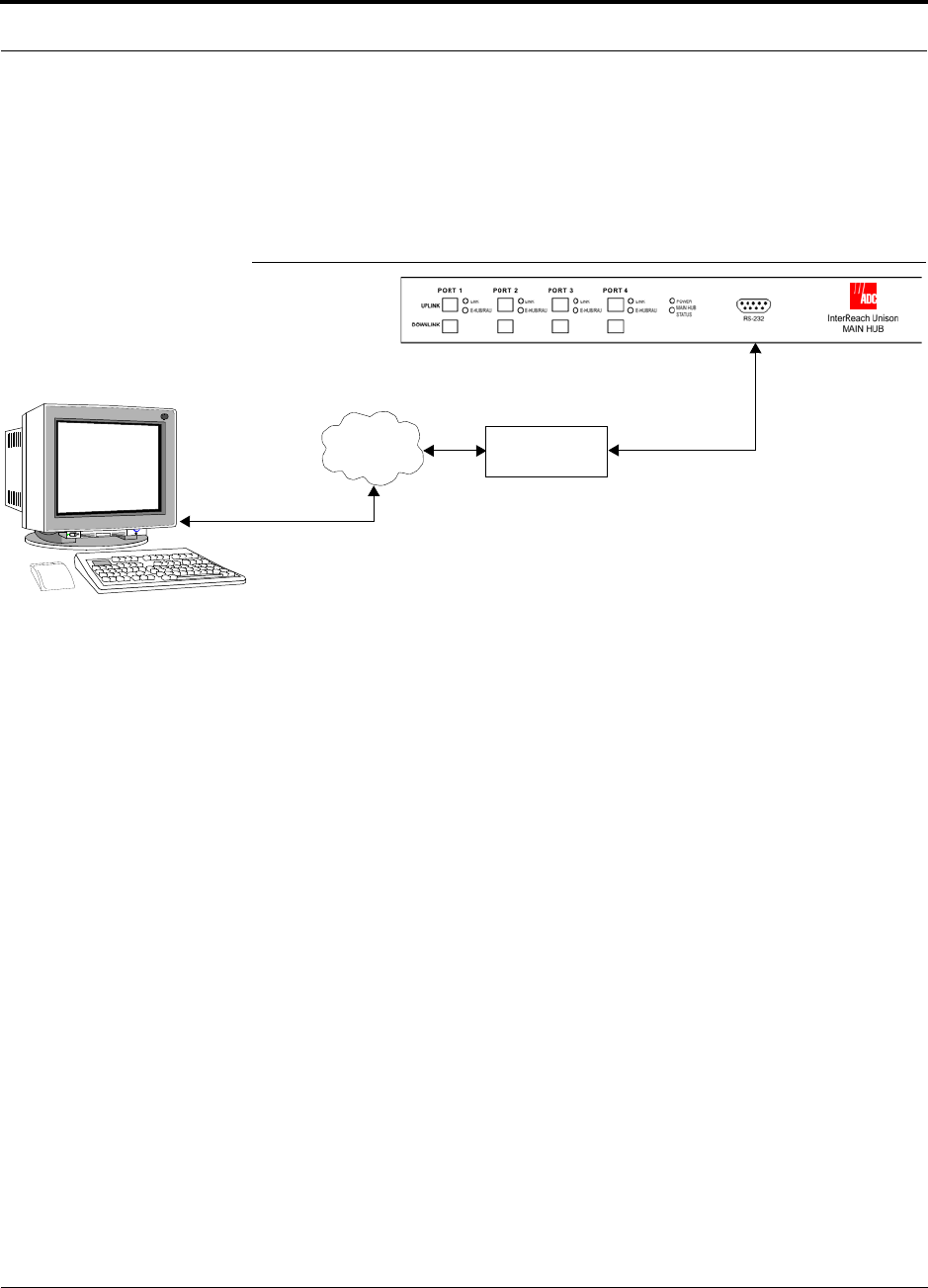
Help Hot Line (U.S. only): 1-800-530-9960 7-55
D-620003-0-20 Rev M CONFIDENTIAL
Alarm Monitoring Connectivity Options
7.8.5 Ethernet and ENET/RS-232 Serial Hub Connection
You can use an Ethernet-to-RS-232 serial hub or converter box to communicate
between the PC and Unison. Testing was performed with an Equinox SST Ethernet
Serial Provider.
Figure 7-24 OA&M Connection using Ethernet and ENET/232 Serial Hub
ENET/RS-232
Serial Hub
TCP/IP
Ethernet
Modem Cable
RJ-45 to DB-9 female
Cat-5E
PC running
or OpsConsole
Software
AdminManager
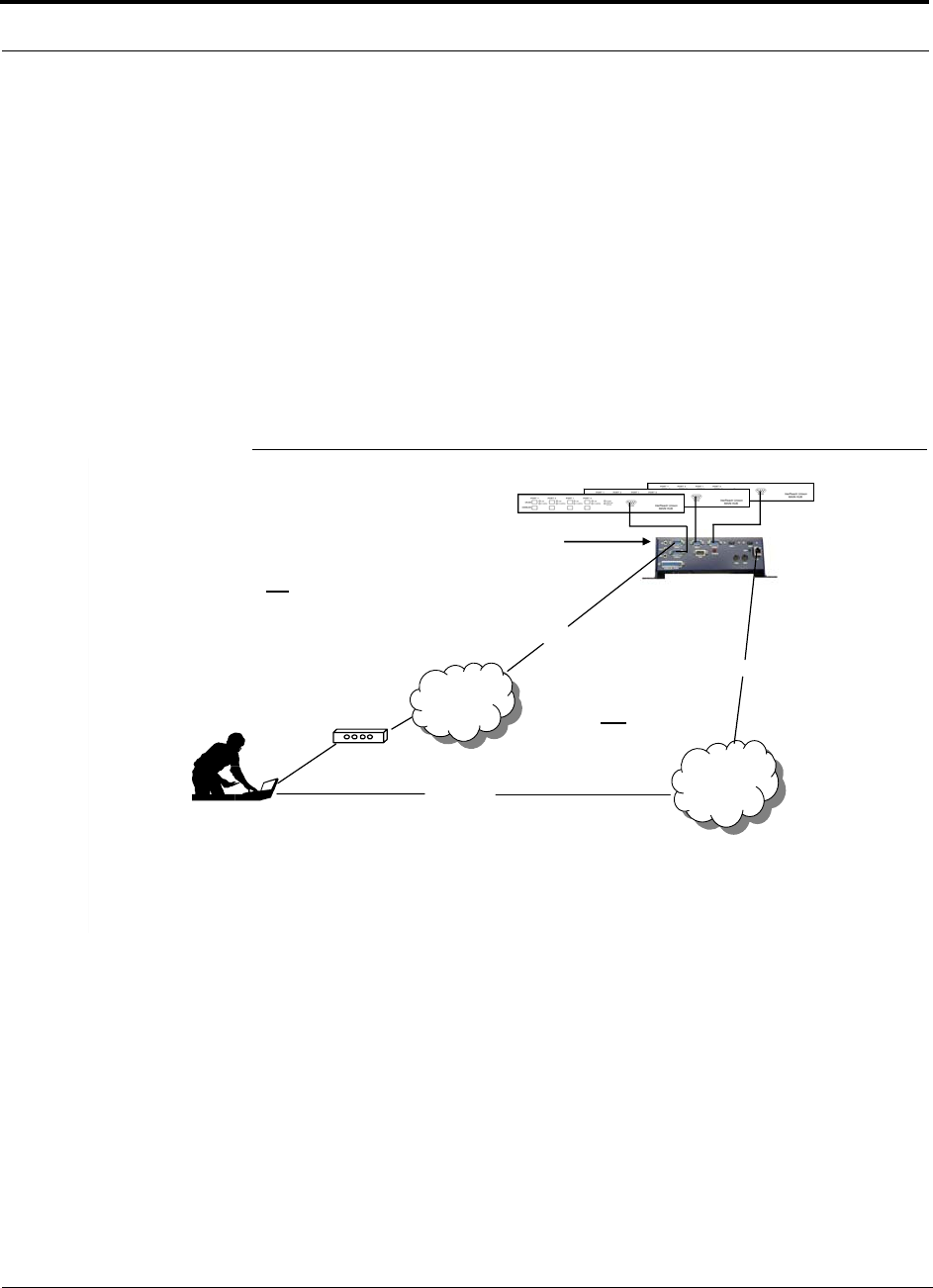
Alarm Monitoring Connectivity Options
7-56 InterReach Unison Installation, Operation, and Reference Manual
CONFIDENTIAL D-620003-0-20 Rev M
7.8.6 Network Interface Unit (NIU)
Faults and warnings can also be diagnosed with SNMP using the NIU. The NIU sup-
ports complete interactions with Unison system:
• Gets, Sets, and Traps/Notification
The NIU enables access to multiple ADC systems at a site as follows:
• NIU-4P-NM-1 (Up to four Unison systems)
• NIU-12P-NM-1 (Up to twelve Unison systems)
The ADC NIU includes a MIB for integrating into the Network Management System
(NMS) and supports SNMPv1 and SNMPv2c.
Figure 7-25 Network Interface Unit (NIU) Configuration Options
The NIU supports
SNMP access to
Unison / Accel systems
via Ethernet or dialup
Modem
Can dedicate one
port for an external
modem
Network
Management
System (SNMP
Manager)
py
OR
PPP /
POTS
PPP /
POTS
Phone Line
Secure
TCP/IP
Network
Secure
TCP/IP
Network
Ethernet
Ethernet
Network
Interface Unit
(SNMP Proxy
Agent)
1 NIU-10P-NM-1 supports up to 10 Unison/Accel systems
NIU-4P-NM-1 supports up to 4 Unison/Accel systems (not expandable)
NIU-12P-NM-1 supports up to 12 Unison/Accel systems
NIU-4P-NM-1 supports up to 4 Unison/Accel systems (not exandable)
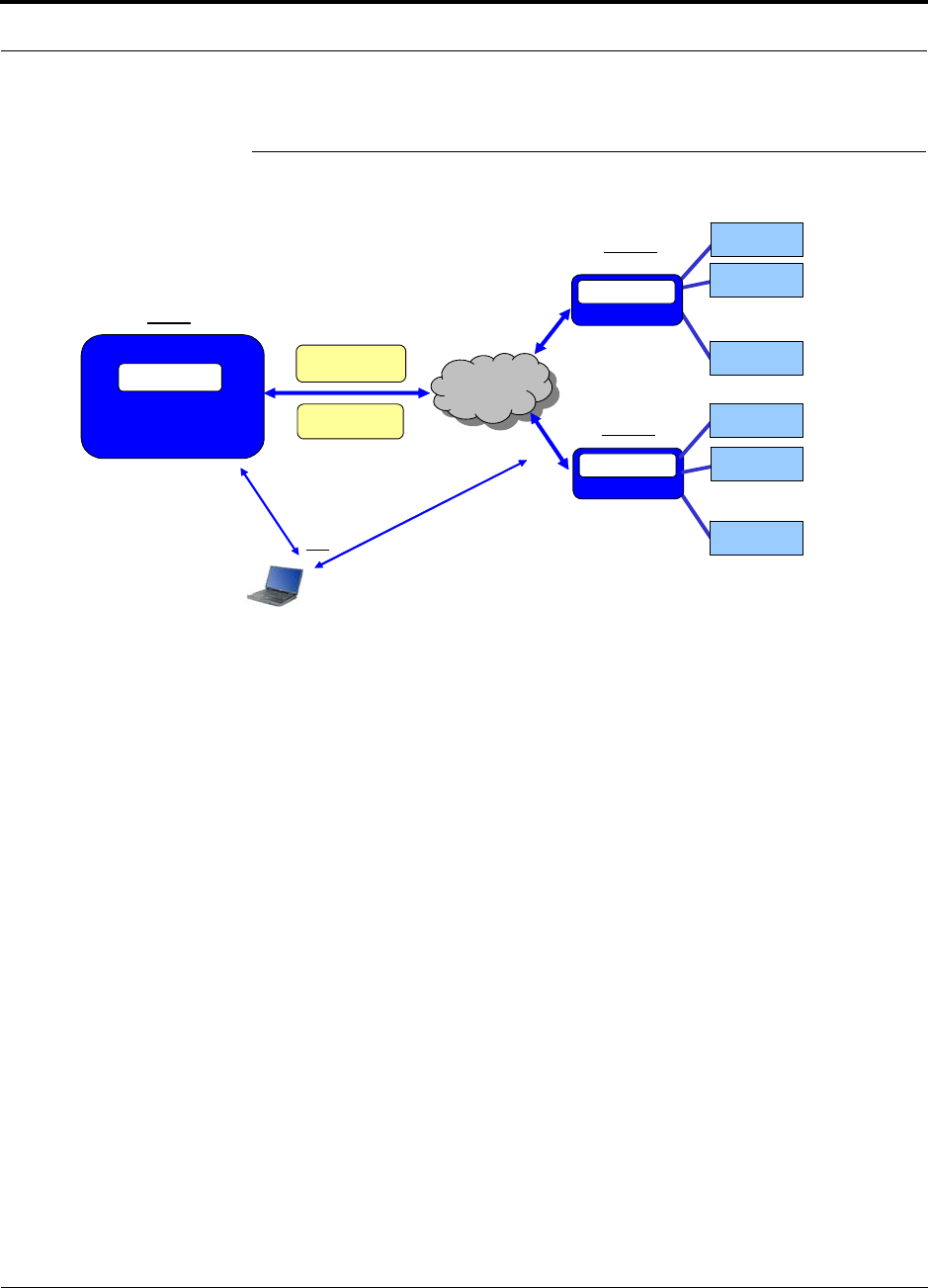
Help Hot Line (U.S. only): 1-800-530-9960 7-57
D-620003-0-20 Rev M CONFIDENTIAL
Alarm Monitoring Connectivity Options
Figure 7-26 Multiple Unison Systems Monitored by a Single Network
Management System
SNMP Reply or
Trap / Notification
SNMP Network
Management System
LGC MIB
SNMP v1/v2C
Get or Set
TCP/IP
Network
TCP/IP
Network
>
…
>
…
Site 1
NOC
NIU 2
SNMP Agent
>
…
Site 2
Unison 10
NIU 1
SNMP Agent Unison 2
Unison 10
Unison 1
Unison 2
Unison 1
Troubleshoot via SNMP
(VPN into NMS) Troubleshoot via AdminManager
(Telnet/VPN or PPP/Dialup into NIU)
Field Technician
For Troubleshooting….
OR

Alarm Monitoring Connectivity Options
7-58 InterReach Unison Installation, Operation, and Reference Manual
CONFIDENTIAL D-620003-0-20 Rev M
This page is intentionally left blank.

InterReach Unison Installation, Operation, and Reference Manual 8-1
D-620003-0-20 Rev M CONFIDENTIAL
SECTION 8 Replacing Unison Components
8.1 Replacing an RAU
Be aware that the new RAU must be the same band as the one you are replacing. If
you replace an RAU with one that is of the wrong band, it will not work.
The Main Hub automatically checks the band of a replaced RAU. There is no need to
issue commands directly from the Main Hub. Therefore, as long as the RAU is of the
correct band, the system will operate properly.
Replacing an RAU
1. Using AdminManager, right-click on the RAU’s icon and select Advanced RAU
Settings from the Unit Commands menu item.
The Advanced RAU Settings window is displayed. Write down the settings so
you can set the new RAU with the same settings.
2. Click CANCEL to close the window.
3. Verify that the new RAU is of the same frequency band as the one replaced.
4. Disconnect the Cat-5/5E/6 cable and antenna cable from the unit to be replaced.
5. Install the new RAU.
6. Connect the antenna cable and then the Cat-5/5E/6 cable to the new RAU.
7. Right-click on the RAU icon and select Advanced RAU Settings from the Unit
Commands menu item.
The Advanced RAU Settings window is displayed.
8. Set the DL/UL attenuation as the old RAU was programmed and click OK.

Replacing an RAU
8-2 InterReach Unison Installation, Operation, and Reference Manual
CONFIDENTIAL D-620003-0-20 Rev M
Perform System Test
When convenient, perform System Test to optimize performance.
During System Test, the entire system is temporarily off-line and no RF is
being transmitted. For a fully loaded system (one Main Hub, four Expansion
Hubs, and 32 RAUs), it can take up to 1.5 minutes to complete the test.
Checking the RAU’s LEDs
1. The RAU’s LINK and ALARM LEDs should blink (green/red) on power up.
• If the LEDs do not blink on power up, replace the RAU.
2. After several seconds both LEDs should change to green, which indicates that the
unit has been successfully replaced, there is communication with the Expansion
Hub, and the RAU band is correct.
a. If the LINK LED remains green and the ALARM LED remains red, verify that
the RAU model is correct for the intended frequency band.
– Disconnect the cable and then reconnect it once; doing this more than once
will not change the result.
b. If both LEDs still don’t change to green, use the AdminManager to determine
the exact nature of the fault and see a recommendation of how to correct it.
c. If both LEDs turn red (after 90 seconds), the Expansion Hub has terminated
communications.

Help Hot Line (U.S. only): 1-800-530-9960 8-3
D-620003-0-20 Rev M CONFIDENTIAL
Replacing an Expansion Hub
8.2 Replacing an Expansion Hub
Replacing an Expansion Hub
1. Turn off the power to the Expansion Hub.
2. Disconnect all Cat-5/5E/6 cables, both fiber cables, and the AC power cord.
3. Replace the Expansion Hub with a new one.
4. Connect the AC power cord, all Cat-5/5E/6 cables, and both fiber cables –
remembering to clean and correctly connect the uplink and downlink fiber.
5. Turn on the power to the Expansion Hub.
AdminManager Tasks
• The Main Hub automatically issues the band setting.
• When convenient, use AdminManager to perform System Test in order to optimize
performance.
During System Test, the entire system is temporarily off-line and no RF is
being transmitted. For a fully loaded system (one Main Hub, four Expansion
Hubs, and 32 RAUs), it can take up to 1.5 minutes to complete the test.
Checking the Expansion Hub’s LEDs
• The LEDs should blink through all states on power up.
• If the LEDs do not blink on power up, replace the Expansion Hub.
• If the LEDs do not illuminate at all, make sure the AC power cable is con-
nected.
• The UL STATUS and DL STATUS LEDs should be green.
• The E-HUB STATUS and POWER LEDs should be green.
• For each RJ-45 port that has an RAU connected:
• The LINK LEDs should be green.
• The RAU LEDs should be green.
It can take several seconds for each Cat-5/5E/6 connection for the LEDs to display
properly.
NOTE: Refer to Section 9 for troubleshooting using the LEDs.

Replacing a Main Hub
8-4 InterReach Unison Installation, Operation, and Reference Manual
CONFIDENTIAL D-620003-0-20 Rev M
8.3 Replacing a Main Hub
You must record the system configuration settings from the old Main Hub’s memory
before replacing the unit (refer to Step 1 below). You will program the new Main Hub
with this information. If the Main Hub is programmed incorrectly, the system will not
work. If the Main Hub is not functioning, get the configuration settings from the
As-Built Document that was created as part of the original installation.
Replacing a Main Hub
1. Using AdminManager, right-click on the Hub’s icon and select Get Parameters
from the System Commands menu item.
The system’s configuration is displayed in the Messages pane.
2. Turn off the power to the Main Hub.
3. Disconnect all cables and the AC power cord.
4. Replace the Hub with a new one.
5. Connect the AC power cord and all cables.
6. Connect the null modem cable to the PC and then to the Hub’s front panel DB-9
serial connector.
7. Start the AdminManager software.
8. Turn on the power to the Hub.
9. Observe the LEDs after turning on the power.
All the LEDs will blink during the initial power up sequence. If the Hub has been
programmed with a band, all LEDs should turn green after the power on sequence
is complete. Power up sequence takes between 1 and 2 minutes depending on the
number of RAUs.
Configure the New Main Hub
1. Right-click the Main Hub’s icon and select Install/Configure System from the
menu.
The System Configuration window is displayed. Write down the settings so you
can set the new Main Hub with the same settings.
2. Select the operating band from the Select Band drop down menu.
3. Enter the uplink and downlink gain in the text boxes.
4. Enter the system label.
5. Click OK.
6. Set the Callback Number and Contact Sense Properties if they are used.
7. Set the current date/time of day.

Help Hot Line (U.S. only): 1-800-530-9960 8-5
D-620003-0-20 Rev M CONFIDENTIAL
Replacing a Main Hub
Checking the Main Hub’s LEDs
• The LEDs should blink through a 5-second test on power up.
• If the LEDs do not blink on power up, replace the Main Hub.
• If the LEDs do not illuminate at all, make sure the AC power cable is con-
nected.
• For each fiber optic port that has a connected Expansion Hub, which has been pro-
grammed with a band:
• The LINK LED should be green.
• The E-HUB/RAU LED should be green indicating that all downstream units are
functioning
• Refer to Section 9.3, “Troubleshooting,” on page 9-3 for more LED states.
NOTE: If there is communication between the Main Hub and the Expansion Hubs,
use the AdminManager to isolate system problems.

Replacing a Main Hub
8-6 InterReach Unison Installation, Operation, and Reference Manual
CONFIDENTIAL D-620003-0-20 Rev M
This page is intentionally left blank.

InterReach Unison Installation, Operation, and Reference Manual 9-1
D-620003-0-20 Rev M CONFIDENTIAL
SECTION 9 Maintenance, Troubleshooting,
and Technical Assistance
There are no user-serviceable parts in any of the Unison components. Faulty or failed
components are fully replaceable through ADC.
Address 2540 Junction Avenue
San Jose, California
95134-1902 USA
Phone 1-408-952-2400
Fax 1-408-952-2410
Help Hot Line 1-800-530-9960 (U.S. only)
+1-408-952-2400 (International)
Web Address http://www.adc.com
e-mail service@lgcwireless.com
9.1 Service
There are no user-serviceable parts in the InterReach Unison system. All units should
be replaced and returned to the factory for service if needed.

Maintenance
9-2 InterReach Unison Installation, Operation, and Reference Manual
CONFIDENTIAL D-620003-0-20 Rev M
9.2 Maintenance
Keep the fiber ports clean and free of dust. No other periodic maintenance of the Uni-
son equipment is required.
To clean the fiber ports:
You can clean the Hub’s fiber ports using canned compressed air or isopropyl alcohol
and cotton swabs.
Considerations:
• If you use compressed air:
• The air must be free of dust, water, and oil.
• Hold the can level during use.
• If using isopropyl alcohol and foam-tipped swab:
• Use only 98% pure or more alcohol.
Procedure using compressed air:
1. Remove the connector’s dust cap.
2. Spray the compressed air away from the unit for a few seconds to clean out the
nozzle and then blow dust particles out of each fiber port.
Procedure using isopropyl alcohol:
1. Remove the connector’s dust cap.
2. Dip a 2.5mm lint-free, foam-tipped swab in isopropyl alcohol and slowly insert
the tip into the connector.
3. Gently twist the swab to clean the connector.
4. Insert a dry swab to dry the connector.
Additionally, you can use compressed air after the alcohol has completely evapo-
rated.

Help Hot Line (U.S. only): 1-800-530-9960 9-3
D-620003-0-20 Rev M CONFIDENTIAL
Troubleshooting
9.3 Troubleshooting
NOTE: Unison has no user-serviceable parts. Faulty or failed units are fully
replaceable through ADC.
Sources of potential problems include:
• Faulty cabling/connector
• Malfunction of one or more Unison components
• Antenna, base station, or repeater problem
• External RF interface
• Tripped circuit breaker
• Using a Null modem cable that does not support full hardware handshaking when
using AdminManager
NOTE: Faulty cabling is the cause of a vast majority of problems. All
Cat-5/5E/6 cable should be tested to TIA/EIA 568-A specifications. The
RAU can be damaged if the cable is not wired correctly.
You must use AdminManager or OpsConsole for troubleshooting the system, use the
LEDs only as backup or for confirmation. However, if there are communication prob-
lems within the system, the LEDs may provide additional information that is not
available using AdminManager.
If you cannot determine the cause of a problem after following the recommended pro-
cedures, call the ADC customer help hot line:
1-800-530-9960 (U.S. only)
+1-408-952-2400 (International)
Or, email us at service@lgcwireless.com.
Please provide the following information:
• Serial number of the unit
• Description of the problem
• Using AdminManager 2.04 or higher, execute the Tools J Get Service Informa-
tion command. Save and email this file to us.
• What is the length of the Cat-5/5E/6 cable? Is it screened?
• Status of the LEDs on the unit
• Was the unit power cycled?

Troubleshooting
9-4 InterReach Unison Installation, Operation, and Reference Manual
CONFIDENTIAL D-620003-0-20 Rev M
9.3.1 Troubleshooting using AdminManager
Use AdminManager software to determine the current faults and warnings for all of
the units in the system. To troubleshoot, start with the Main Hub’s faults AND warn-
ings, then proceed to each of the Expansion Hubs, finishing with each of the RAUs.
NOTE: AdminManager v2.04 or higher displays events (faults, warnings,
or status messages) depending on your view preference. To change your
view preference, refer to Section 3.4.2, “View Preference,” on page 3-10.
NOTE: Faults usually impact service; warnings may impact service; status
does not generally impact service, but contains important information that
you should not ignore.
System Troubleshooting
Get All Current Faults & Warnings (or Get Faults; or Get Current Faults, Warnings,
and Status Messages). This gives the current status of the system depending on view
preferences, and should be used to determine if there is more than one fault/warning
in the system. Point to the top most icon or the Main Hub in the hierarchical tree, and
right click to see the Pull down menu. Select: SYSTEM COMMANDS/GET FAULTS (OR
GET CURRENT FAULTS AND WARNINGS; OR GET CURRENT FAULTS, WARNINGS, AND STA-
TUS MESSAGES).
NOTE: System commands always take longer to execute than component
commands.
NOTE: This RAU icon indicates there is fault on the RAU. This icon
indicates a disconnected device. You cannot request status on a discon-
nected device.
Component Troubleshooting
• If a device displays as an fault icon, right click on the icon, and select UNIT COM-
MANDS/ GET CURRENT FAULTS. If a device displays as a warning or information
icon, right click on the icon, and select UNIT COMMANDS/ GET CURRENT WARNINGS
AND STATUS MESSAGES.

Help Hot Line (U.S. only): 1-800-530-9960 9-5
D-620003-0-20 Rev M CONFIDENTIAL
Troubleshooting
9.3.1.1 Troubleshooting Recommendations
• Some things that can be done, depending on the device fault or warning include:
a. Hardware faults on Expansion Hub.
– Try swapping fiber with another Expansion Hub at the Main Hub.
– Try cleaning the fiber and the fiber ports with alcohol foam tip swab and
compressed air. See Section , “To clean the fiber ports:,” on page 9-2.
– Power cycle the Expansion Hub.
b. Issue a CLEAR ALL DISCONNECTS at the Main Hub.
c. Power cycle the Main Hub.
d. RAU hardware faults. Try swapping the Cat-5/5E/6 at Expansion Hub with a
good Cat-5/5E/6 cable.
e. If there is an RF14 Fault and the Cat-5/5E/6 run has an Extender, check that it
is installed correctly. See Section , “Installing a Cat-5 Extender,” on page
7-30.
f. Try isolating the system components:
– Check to see if the whole system is effected or a portion of the system.
– If the whole system is effected, disconnect the DAS system from the RF
source and see if the RF source is working.
– Continue to isolate by disabling portions of the system. Use the UNIT COM-
MANDS/SET OUT-OF-SERVICE and SET IN-SERVICE.
9.3.1.2 Fault Indications
Once all of the units are powered on and the cable connections are made, the faults
from each unit can be requested using AdminManager. Start with the Main Hub and
work downstream.
NOTE: AdminManager v2.04 or higher displays events (faults, warnings,
or status messages) depending on your view preference. To change your
view preference, refer to Section 3.4.2, “View Preference,” on page 3-10.
Resolve all faults first and then check the warnings. Take appropriate action to
resolve the faults, as indicated in the following tables. In cases where there is more
than one possible cause, they are listed from the “most likely” to the “least likely”
cause. Actions are listed in the order that they should be performed; not all actions
may need to be done.
Faults messages are displayed in the Messages pane in red lettering.

Troubleshooting
9-6 InterReach Unison Installation, Operation, and Reference Manual
CONFIDENTIAL D-620003-0-20 Rev M
NOTE: If you have a red STATUS LED without a fault message, it probably
indicates that the unit is locked out.
NOTE: The tables below contain messages for all versions of firmware.
Main Hub Faults
Table 9-1 Faults Reported by the Main Hub
Alarm Message Action
{MF01}Software error occurred and recov-
ered If this happens repeatedly, replace the MH. (Log entry only.)
{MF02}Software error occurred and recov-
ered If this happens repeatedly, replace the MH. (Log entry only.)
{MF03}Software error occurred and recov-
ered If this happens repeatedly, replace the MH. (Log entry only.)
{MF04}Software error occurred and recov-
ered If this happens repeatedly, replace the MH. (Log entry only.)
{MF05}Software error occurred and recov-
ered If this happens repeatedly, replace the MH. (Log entry only.)
{MF06}MH power cycle If AC mains are not cycled, replace the MH.
{MF09}Temperature is high Replace the Main Hub if there is fan failure. Check fan for rotation, airflow
blockage, and dust. Check room environmental controls.
{MF10} System Error Lockout Check MH faults, system is out of service due to an MH fault.
{MF11} Commanded Out-of-Service Command In-Service to restore operation.
{MF13}Hardware failure (Power Supply) Replace the MH.
{MF14}Hardware failure (DL Laser) Replace the MH.
{MF15}Failed to perform system test (PLL
unlock) Unable to perform system end-to-end test, replace the MH when possible.
{MF17}Hardware failure (SPI) Cycle power once. If fault persists, replace the MH.
{MF18}Hardware failure (DL PLL Unlock) Cycle power once. If fault persists, replace the MH.
{MF19}Hardware failure (DL PLL Unlock) Cycle power once. If fault persists, replace the MH.
{MF20}Hardware failure (DL Pilot PLL
Unlock) Cycle power once. If fault persists, replace the MH.
{MF21}Hardware failure (UL PLL Unlock) Cycle power once. If fault persists, replace the MH.
{MF22}Hardware failure (UL PLL Unlock) Cycle power once. If fault persists, replace the MH.
{MF23}Hardware failure (UL PLL Unlock) Cycle power once. If fault persists, replace the MH.

Help Hot Line (U.S. only): 1-800-530-9960 9-7
D-620003-0-20 Rev M CONFIDENTIAL
Troubleshooting
{MF24}Frequency band not programmed Use AdminManager to program the frequency band.
{MF25}Hardware failure (DL Pilot too
low) Cycle power once. If fault persists, replace the MH.
{MF26}Hardware failure (DL Pilot too
high) Cycle power once. If fault persists, replace the MH.
{MF27}Failed to perform system test (Test
tone too high) Unable to perform system end-to-end test, replace the Main Hub when possi-
ble.
{MF28}Failed to perform system test (Test
tone too low) Unable to perform system end-to-end test, replace the Main Hub when possi-
ble.
{MF29}Hardware failure (DL Path) Replace the Main Hub.
{MF30}Hardware failure (UL Path) Re-run system test. Swap first two EHs and re-run system test. If fault persists,
replace the MH when possible.
{MF33}Port 1 UL RF path has excessive
gain If fault common to more than one port, replace the MH. If only one port has the
fault, try another MH port. If no fault is reported, flag the previous port as unus-
able and replace the MH when possible. Otherwise, replace the EH.
{MF34} Port 2 UL RF path has excessive
gain If fault common to more than one port, replace the MH. If only one port has the
fault, try another MH port. If no fault is reported, flag the previous port as unus-
able and replace the MH when possible. Otherwise, replace the EH.
{MF35} Port 3 UL RF path has excessive
gain If fault common to more than one port, replace the MH. If only one port has the
fault, try another MH port. If no fault is reported, flag the previous port as unus-
able and replace the MH when possible. Otherwise, replace the EH.
{MF36} Port 4 UL RF path has excessive
gain If fault common to more than one port, replace the MH. If only one port has the
fault, try another MH port. If no fault is reported, flag the previous port as unus-
able and replace the MH when possible. Otherwise, replace the EH.
{MF37} Port 1 UL RF path loss is too high The uplink RF loss is above the recommended minimum. If codes MS13-MS16
are also present, the fiber is the most likely problem. Clean the fiber ports and
connectors. Ensure that the fiber connector is correctly seated.
If codes MS13-MS16 are not present, disconnect both downlink and uplink
fiber at the Main Hub. Wait 10 seconds, then re-connect downlink and uplink
fiber.
If fault common to more than one port, replace the MH. If only one port has the
fault, try another MH port. If no fault is reported, flag the previous port as unus-
able and replace the MH when possible. Otherwise, replace the EH.
{MF38} Port 2 UL RF path loss is too high The uplink RF loss is above the recommended minimum. If codes MS13-MS16
are also present, the fiber is the most likely problem. Clean the fiber ports and
connectors. Ensure that the fiber connector is correctly seated.
If codes MS13-MS16 are not present, disconnect both downlink and uplink
fiber at the Main Hub. Wait 10 seconds, then re-connect downlink and uplink
fiber.
If fault common to more than one port, replace the MH. If only one port has the
fault, try another MH port. If no fault is reported, flag the previous port as unus-
able and replace the MH when possible. Otherwise, replace the EH.
Table 9-1 Faults Reported by the Main Hub (continued)

Troubleshooting
9-8 InterReach Unison Installation, Operation, and Reference Manual
CONFIDENTIAL D-620003-0-20 Rev M
{MF39} Port 3 UL RF path loss is too high The uplink RF loss is above the recommended minimum. If codes MS13-MS16
are also present, the fiber is the most likely problem. Clean the fiber ports and
connectors. Ensure that the fiber connector is correctly seated.
If codes MS13-MS16 are not present, disconnect both downlink and uplink
fiber at the Main Hub. Wait 10 seconds, then re-connect downlink and uplink
fiber.
If fault common to more than one port, replace the MH. If only one port has the
fault, try another MH port. If no fault is reported, flag the previous port as unus-
able and replace the MH when possible. Otherwise, replace the EH.
{MF40} Port 4 UL RF path loss is too high The uplink RF loss is above the recommended minimum. If codes MS13-MS16
are also present, the fiber is the most likely problem. Clean the fiber ports and
connectors. Ensure that the fiber connector is correctly seated.
If codes MS13-MS16 are not present, disconnect both downlink and uplink
fiber at the Main Hub. Wait 10 seconds, then re-connect downlink and uplink
fiber.
If fault common to more than one port, replace the MH. If only one port has the
fault, try another MH port. If no fault is reported, flag the previous port as unus-
able and replace the MH when possible. Otherwise, replace the EH.
{MF41}No communication with EH 1 If fault common to more than one port, replace the MH. If only one port has the
fault, try another MH port. If no fault is reported, the MH fiber port is dirty or
bad. Clean DL & UL fiber ports on both the MH and EH. Measure DL & UL
optical loss. Check for flat polished fiber connectors. Replace the EH.
{MF42}No communication with EH 2 If fault common to more than one port, replace the MH. If only one port has the
fault, try another MH port. If no fault is reported, the MH fiber port is dirty or
bad. Clean DL & UL fiber ports on both the MH and EH. Measure DL & UL
optical loss. Check for flat polished fiber connectors. Replace the EH.
{MF43}No communication with EH 3 If fault common to more than one port, replace the MH. If only one port has the
fault, try another MH port. If no fault is reported, the MH fiber port is dirty or
bad. Clean DL & UL fiber ports on both the MH and EH. Measure DL & UL
optical loss. Check for flat polished fiber connectors. Replace the EH.
{MF44}No communication with EH 4 If fault common to more than one port, replace the MH. If only one port has the
fault, try another MH port. If no fault is reported, the MH fiber port is dirty or
bad. Clean DL & UL fiber ports on both the MH and EH. Measure DL & UL
optical loss. Check for flat polished fiber connectors. Replace the EH.
{MF45}EH 1 disconnected Try another port. If no connection, cycle EH power and confirm UL STATUS
LED is green for 90 seconds. Check UL fiber connection(s). Clean fiber con-
nectors and ports on MH and EH. Measure UL optical loss. Use “Clear All Dis-
connect Status” command to clear fault, or physically connect the EH.
{MF46}EH 2 disconnected Try another port. If no connection, cycle EH power and confirm UL STATUS
LED is green for 90 seconds. Check UL fiber connection(s). Clean fiber con-
nectors and ports on MH and EH. Measure UL optical loss. Use “Clear All Dis-
connect Status” command to clear fault, or physically connect the EH.
Table 9-1 Faults Reported by the Main Hub (continued)

Help Hot Line (U.S. only): 1-800-530-9960 9-9
D-620003-0-20 Rev M CONFIDENTIAL
Troubleshooting
{MF47}EH 3 disconnected Try another port. If no connection, cycle EH power and confirm UL STATUS
LED is green for 90 seconds. Check UL fiber connection(s). Clean fiber con-
nectors and ports on MH and EH. Measure UL optical loss. Use “Clear All Dis-
connect Status” command to clear fault, or physically connect the EH.
{MF48}EH 4 disconnected Try another port. If no connection, cycle EH power and confirm UL STATUS
LED is green for 90 seconds. Check UL fiber connection(s). Clean fiber con-
nectors and ports on MH and EH. Measure UL optical loss. Use “Clear All Dis-
connect Status” command to clear fault, or physically connect the EH.
Table 9-1 Faults Reported by the Main Hub (continued)

Troubleshooting
9-10 InterReach Unison Installation, Operation, and Reference Manual
CONFIDENTIAL D-620003-0-20 Rev M
Expansion Hub Faults
Table 9-2 Faults Reported by the Expansion Hub
Alarm Message Action
{EF01}Software error occurred and recov-
ered If this happens repeatedly, replace the EH. (Log entry only.)
{EF02}Software error occurred and recov-
ered If this happens repeatedly, replace the EH. (Log entry only.)
{EF03}Software error occurred and recov-
ered If this happens repeatedly, replace the EH. (Log entry only.)
{EF04}Software error occurred and recov-
ered If this happens repeatedly, replace the EH. (Log entry only.)
{EF05}Software error occurred and recov-
ered If this happens repeatedly, replace the EH. (Log entry only.)
{EF06}Hardware failure (SPI) Cycle power once. If fault persists, replace the EH.
{EF07}Temperature is too high Replace the EH if fan failure. Check fan for rotation, airflow blockage, and
dust. Check room environmental controls.
{EF08}Frequency band not programmed Use AdminManager to program the frequency band.
{EF09}Hardware failure (PLL Unlock) If fault common to more than one EH, replace the MH. If only one EH has the
fault, try another MH port. If no fault is reported, flag the previous port as unus-
able and replace the MH when possible. Otherwise, replace the EH.
{EF10}Excessive DL optical loss Normally this fault is only logged because the optical loss is below the absolute
minimum. EH DL LED is red.
Clean fiber connectors and ports, and check DL cable for excessive optical loss.
If fault common to more than one EH, replace the MH. If only one EH has the
fault, try another port on the MH. If no fault is reported, flag the previous port
as unusable and replace the MH when possible. Otherwise, replace the EH.
{EF11}The DL RF path has excessive gain If fault common to more than one EH, replace the MH. If only one EH has the
fault, try another MH port. If no fault is reported, flag the previous port as unus-
able and replace the MH when possible. Otherwise, replace the EH.
{EF12}The DL RF path loss is too high Clean fiber connectors and ports, and check DL cable for excessive optical loss.
If fault common to more than one EH, replace the MH. If only one EH has the
fault, try another port on the MH. If no fault is reported, flag the previous port
as unusable and replace the MH when possible. Otherwise, replace the EH.
{EF13}Hardware failure possibly resulting
in degraded performance Replace the EH.
{EF14}Hardware failure possibly resulting
in degraded performance Replace the EH.
{EF15}Hardware failure (UL Laser) Replace the EH.
{EF16}No MH communications Clean fiber connectors and ports, and check cables for excessive optical loss. If
fault common to more than one EH, replace the MH. If only one EH has the
fault, try another port on the MH. If no fault is reported, flag the previous port
as unusable and replace the MH when possible. Otherwise, replace the EH.

Help Hot Line (U.S. only): 1-800-530-9960 9-11
D-620003-0-20 Rev M CONFIDENTIAL
Troubleshooting
{EF17}RAU 1 disconnected Check Cat-5/5E/6 cable for shorts/opens, especially on new install. Try another
EH port. If no fault is reported flag the previous port as unusable and replace
the EH when possible. Otherwise, replace the RAU. Use “Clear All Disconnect
Status” command to clear fault, or physically connect the RAU.
{EF18}RAU 2 disconnected Check Cat-5/5E/6 cable for shorts/opens, especially on new install. Try another
EH port. If no fault is reported flag the previous port as unusable and replace
the EH when possible. Otherwise, replace the RAU. Use “Clear All Disconnect
Status” command to clear fault, or physically connect the RAU.
{EF19}RAU 3 disconnected Check Cat-5/5E/6 cable for shorts/opens, especially on new install. Try another
EH port. If no fault is reported flag the previous port as unusable and replace
the EH when possible. Otherwise, replace the RAU. Use “Clear All Disconnect
Status” command to clear fault, or physically connect the RAU.
{EF20}RAU 4 disconnected Check Cat-5/5E/6 cable for shorts/opens, especially on new install. Try another
EH port. If no fault is reported flag the previous port as unusable and replace
the EH when possible. Otherwise, replace the RAU. Use “Clear All Disconnect
Status” command to clear fault, or physically connect the RAU.
{EF21}RAU 5 disconnected Check Cat-5/5E/6 cable for shorts/opens, especially on new install. Try another
EH port. If no fault is reported flag the previous port as unusable and replace
the EH when possible. Otherwise, replace the RAU. Use “Clear All Disconnect
Status” command to clear fault, or physically connect the RAU.
{EF22}RAU 6 disconnected Check Cat-5/5E/6 cable for shorts/opens, especially on new install. Try another
EH port. If no fault is reported flag the previous port as unusable and replace
the EH when possible. Otherwise, replace the RAU. Use “Clear All Disconnect
Status” command to clear fault, or physically connect the RAU.
{EF23}RAU 7 disconnected Check Cat-5/5E/6 cable for shorts/opens, especially on new install. Try another
EH port. If no fault is reported flag the previous port as unusable and replace
the EH when possible. Otherwise, replace the RAU. Use “Clear All Disconnect
Status” command to clear fault, or physically connect the RAU.
{EF24}RAU 8 disconnected Check Cat-5/5E/6 cable for shorts/opens, especially on new install. Try another
EH port. If no fault is reported flag the previous port as unusable and replace
the EH when possible. Otherwise, replace the RAU. Use “Clear All Disconnect
Status” command to clear fault, or physically connect the RAU.
{EF25}Port 1 UL RF path loss is too high CAT-5 cable is poorly terminated, re-crimp the connector; no RF uplink is
detected at all.
Check Cat-5E/6 cable loss, especially on new install. Check Cat-5 Extender, if
present. If fault present on all EH ports, replace the EH. Otherwise, try another
EH port. If no fault is reported, flag the previous port as unusable and replace
the EH when possible. Otherwise, replace the RAU.
{EF26} Port 2 UL RF path loss is too high CAT-5 cable is poorly terminated, re-crimp the connector; no RF uplink is
detected at all.
Check Cat-5E/6 cable loss, especially on new install. Check Cat-5 Extender, if
present. If fault present on all EH ports, replace the EH. Otherwise, try another
EH port. If no fault is reported, flag the previous port as unusable and replace
the EH when possible. Otherwise, replace the RAU.
Table 9-2 Faults Reported by the Expansion Hub (continued)

Troubleshooting
9-12 InterReach Unison Installation, Operation, and Reference Manual
CONFIDENTIAL D-620003-0-20 Rev M
{EF27} Port 3 UL RF path loss is too high CAT-5 cable is poorly terminated, re-crimp the connector; no RF uplink is
detected at all.
Check Cat-5E/6 cable loss, especially on new install. Check Cat-5 Extender, if
present. If fault present on all EH ports, replace the EH. Otherwise, try another
EH port. If no fault is reported, flag the previous port as unusable and replace
the EH when possible. Otherwise, replace the RAU.
{EF28} Port 4 UL RF path loss is too high CAT-5 cable is poorly terminated, re-crimp the connector; no RF uplink is
detected at all.
Check Cat-5E/6 cable loss, especially on new install. Check Cat-5 Extender, if
present. If fault present on all EH ports, replace the EH. Otherwise, try another
EH port. If no fault is reported, flag the previous port as unusable and replace
the EH when possible. Otherwise, replace the RAU.
{EF29} Port 5 UL RF path loss is too high CAT-5 cable is poorly terminated, re-crimp the connector; no RF uplink is
detected at all.
Check Cat-5E/6 cable loss, especially on new install. Check Cat-5 Extender, if
present. If fault present on all EH ports, replace the EH. Otherwise, try another
EH port. If no fault is reported, flag the previous port as unusable and replace
the EH when possible. Otherwise, replace the RAU.
{EF30} Port 6 UL RF path loss is too high CAT-5 cable is poorly terminated, re-crimp the connector; no RF uplink is
detected at all.
Check Cat-5E/6 cable loss, especially on new install. Check Cat-5 Extender, if
present. If fault present on all EH ports, replace the EH. Otherwise, try another
EH port. If no fault is reported, flag the previous port as unusable and replace
the EH when possible. Otherwise, replace the RAU.
{EF31} Port 7 UL RF path loss is too high CAT-5 cable is poorly terminated, re-crimp the connector; no RF uplink is
detected at all.
Check Cat-5E/6 cable loss, especially on new install. Check Cat-5 Extender, if
present. If fault present on all EH ports, replace the EH. Otherwise, try another
EH port. If no fault is reported, flag the previous port as unusable and replace
the EH when possible. Otherwise, replace the RAU.
{EF32} Port 8 UL RF path loss is too high CAT-5 cable is poorly terminated, re-crimp the connector; no RF uplink is
detected at all.
Check Cat-5E/6 cable loss, especially on new install. Check Cat-5 Extender, if
present. If fault present on all EH ports, replace the EH. Otherwise, try another
EH port. If no fault is reported, flag the previous port as unusable and replace
the EH when possible. Otherwise, replace the RAU.
{EF33}Port 1 DL RF path too low Try another port, if fault persists replace the EH. Otherwise, flag previous port
as unusable and replace the EH when possible
{EF34}Port 2 DL RF path too low Try another port, if fault persists replace the EH. Otherwise, flag previous port
as unusable and replace the EH when possible
{EF35}Port 3 DL RF path too low Try another port, if fault persists replace the EH. Otherwise, flag previous port
as unusable and replace the EH when possible
{EF36}Port 4 DL RF path too low Try another port, if fault persists replace the EH. Otherwise, flag previous port
as unusable and replace the EH when possible
Table 9-2 Faults Reported by the Expansion Hub (continued)

Help Hot Line (U.S. only): 1-800-530-9960 9-13
D-620003-0-20 Rev M CONFIDENTIAL
Troubleshooting
{EF37}Port 5 DL RF path too low Try another port, if fault persists replace the EH. Otherwise, flag previous port
as unusable and replace the EH when possible
{EF38}Port 6 DL RF path too low Try another port, if fault persists replace the EH. Otherwise, flag previous port
as unusable and replace the EH when possible
{EF39}Port 7 DL RF path too low Try another port, if fault persists replace the EH. Otherwise, flag previous port
as unusable and replace the EH when possible
{EF40}Port 8 DL RF path too low Try another port, if fault persists replace the EH. Otherwise, flag previous port
as unusable and replace the EH when possible
{EF41}No communication with RAU 1 Check Cat-5/5E/6 cable for shorts/opens, especially on new install. Try another
EH port. If no fault is reported, flag the previous port as unusable and replace
the EH when possible. Otherwise, replace the RAU.
{EF42}No communication with RAU 2 Check Cat-5/5E/6 cable for shorts/opens, especially on new install. Try another
EH port. If no fault is reported, flag the previous port as unusable and replace
the EH when possible. Otherwise, replace the RAU.
{EF43}No communication with RAU 3 Check Cat-5/5E/6 cable for shorts/opens, especially on new install. Try another
EH port. If no fault is reported, flag the previous port as unusable and replace
the EH when possible. Otherwise, replace the RAU.
{EF44}No communication with RAU 4 Check Cat-5/5E/6 cable for shorts/opens, especially on new install. Try another
EH port. If no fault is reported, flag the previous port as unusable and replace
the EH when possible. Otherwise, replace the RAU.
{EF45}No communication with RAU 5 Check Cat-5/5E/6 cable for shorts/opens, especially on new install. Try another
EH port. If no fault is reported, flag the previous port as unusable and replace
the EH when possible. Otherwise, replace the RAU.
{EF46}No communication with RAU 6 Check Cat-5/5E/6 cable for shorts/opens, especially on new install. Try another
EH port. If no fault is reported, flag the previous port as unusable and replace
the EH when possible. Otherwise, replace the RAU.
{EF47}No communication with RAU 7 Check Cat-5/5E/6 cable for shorts/opens, especially on new install. Try another
EH port. If no fault is reported, flag the previous port as unusable and replace
the EH when possible. Otherwise, replace the RAU.
{EF48}No communication with RAU 8 Check Cat-5/5E/6 cable for shorts/opens, especially on new install. Try another
EH port. If no fault is reported, flag the previous port as unusable and replace
the EH when possible. Otherwise, replace the RAU.
{EF49}RAU 1 over current Port power trip. Disconnect the CAT-5 cable and issue 'Clear All Disconnects'
command. The EH port LEDs should be Off/Off. If they are not, the port has
been damaged and can no longer be used. Check the CAT-5 cable, re-crimp the
connector. If the fault persists, replace the RAU.
Check Cat-5E/6 cable for shorts/opens, especially on new install. Try another
EH port. If no fault is reported, flag the previous port as unusable and replace
the EH when possible. Otherwise, replace the RAU. Use “Clear All Disconnect
Status” command to clear fault, or power-cycle the EH.
Table 9-2 Faults Reported by the Expansion Hub (continued)

Troubleshooting
9-14 InterReach Unison Installation, Operation, and Reference Manual
CONFIDENTIAL D-620003-0-20 Rev M
{EF50}RAU 2 over current Port power trip. Disconnect the CAT-5 cable and issue 'Clear All Disconnects'
command. The EH port LEDs should be Off/Off. If they are not, the port has
been damaged and can no longer be used. Check the CAT-5 cable, re-crimp the
connector. If the fault persists, replace the RAU.
Check Cat-5E/6 cable for shorts/opens, especially on new install. Try another
EH port. If no fault is reported, flag the previous port as unusable and replace
the EH when possible. Otherwise, replace the RAU. Use “Clear All Disconnect
Status” command to clear fault, or power-cycle the EH.
{EF51}RAU 3 over current Port power trip. Disconnect the CAT-5 cable and issue 'Clear All Disconnects'
command. The EH port LEDs should be Off/Off. If they are not, the port has
been damaged and can no longer be used. Check the CAT-5 cable, re-crimp the
connector. If the fault persists, replace the RAU.
Check Cat-5E/6 cable for shorts/opens, especially on new install. Try another
EH port. If no fault is reported, flag the previous port as unusable and replace
the EH when possible. Otherwise, replace the RAU. Use “Clear All Disconnect
Status” command to clear fault, or power-cycle the EH.
{EF52}RAU 4 over current Port power trip. Disconnect the CAT-5 cable and issue 'Clear All Disconnects'
command. The EH port LEDs should be Off/Off. If they are not, the port has
been damaged and can no longer be used. Check the CAT-5 cable, re-crimp the
connector. If the fault persists, replace the RAU.
Check Cat-5E/6 cable for shorts/opens, especially on new install. Try another
EH port. If no fault is reported, flag the previous port as unusable and replace
the EH when possible. Otherwise, replace the RAU. Use “Clear All Disconnect
Status” command to clear fault, or power-cycle the EH.
{EF53}RAU 5 over current Port power trip. Disconnect the CAT-5 cable and issue 'Clear All Disconnects'
command. The EH port LEDs should be Off/Off. If they are not, the port has
been damaged and can no longer be used. Check the CAT-5 cable, re-crimp the
connector. If the fault persists, replace the RAU.
Check Cat-5E/6 cable for shorts/opens, especially on new install. Try another
EH port. If no fault is reported, flag the previous port as unusable and replace
the EH when possible. Otherwise, replace the RAU. Use “Clear All Disconnect
Status” command to clear fault, or power-cycle the EH.
{EF54}RAU 6 over current Port power trip. Disconnect the CAT-5 cable and issue 'Clear All Disconnects'
command. The EH port LEDs should be Off/Off. If they are not, the port has
been damaged and can no longer be used. Check the CAT-5 cable, re-crimp the
connector. If the fault persists, replace the RAU.
Check Cat-5E/6 cable for shorts/opens, especially on new install. Try another
EH port. If no fault is reported, flag the previous port as unusable and replace
the EH when possible. Otherwise, replace the RAU. Use “Clear All Disconnect
Status” command to clear fault, or power-cycle the EH.
Table 9-2 Faults Reported by the Expansion Hub (continued)

Help Hot Line (U.S. only): 1-800-530-9960 9-15
D-620003-0-20 Rev M CONFIDENTIAL
Troubleshooting
{EF55}RAU 7 over current Port power trip. Disconnect the CAT-5 cable and issue 'Clear All Disconnects'
command. The EH port LEDs should be Off/Off. If they are not, the port has
been damaged and can no longer be used. Check the CAT-5 cable, re-crimp the
connector. If the fault persists, replace the RAU.
Check Cat-5E/6 cable for shorts/opens, especially on new install. Try another
EH port. If no fault is reported, flag the previous port as unusable and replace
the EH when possible. Otherwise, replace the RAU. Use “Clear All Disconnect
Status” command to clear fault, or power-cycle the EH.
{EF56}RAU 8 over current Port power trip. Disconnect the CAT-5 cable and issue 'Clear All Disconnects'
command. The EH port LEDs should be Off/Off. If they are not, the port has
been damaged and can no longer be used. Check the CAT-5 cable, re-crimp the
connector. If the fault persists, replace the RAU.
Check Cat-5E/6 cable for shorts/opens, especially on new install. Try another
EH port. If no fault is reported, flag the previous port as unusable and replace
the EH when possible. Otherwise, replace the RAU. Use “Clear All Disconnect
Status” command to clear fault, or power-cycle the EH.
{EF60} Internal fault lockout Check the EH for faults. EH/RAUs are out of service on command from the
EH.
{EF61} External fault lockout Check the MH for faults. The EH/RAUs are out of service on command of the
MH.
{EF62 Commanded Out-of-Service Command In-Service to restore operation.
{EF63} 36 VAC Shutdown 36 VAC shutdown due to EH over temperature. Automatic recovery is possible
when internal ambient temperature drops below 65 degrees Centigrade.
Table 9-2 Faults Reported by the Expansion Hub (continued)

Troubleshooting
9-16 InterReach Unison Installation, Operation, and Reference Manual
CONFIDENTIAL D-620003-0-20 Rev M
Remote Access Unit Faults
Table 9-3 Faults Reported by the RAU
Alarm Message Action
{RF01}Software error occurred and recov-
ered If this happens repeatedly, replace the RAU. (Log entry only.)
{RF02}Software error occurred and recov-
ered If this happens repeatedly, replace the RAU. (Log entry only.)
{RF03}Software error occurred and recov-
ered If this happens repeatedly, replace the RAU. (Log entry only.)
{RF04}Software error occurred and recov-
ered If this happens repeatedly, replace the RAU. (Log entry only.)
{RF05}Software error occurred and recov-
ered If this happens repeatedly, replace the RAU. (Log entry only.)
{RF06}Hardware failure (SPI) Cycle the power once. If the fault persists, replace the RAU
{RF09}Temperature is too high Check for proper installation. Check environmental controls, move the RAU to
a cooler environment.
{RF10}DC Power supplied by the
EH/Accel Hub is too low Check the CAT-5E/6 cable for shorts/opens, especially on new installations.
Check the CAT-5 Extender, if present. If the fault is common to more than one
RAU, replace the EH/Accel Hub. Try another port. If no fault is reported, flag
the previous port as unusable and replace the Hub when possible. Otherwise,
replace the RAU.
{RF11}DC Power supplied by the
EH/Accel Hub is too high Check the CAT-5E/6 cable for shorts/opens, especially on new installation.
Check the CAT-5 Extender, if present. If the fault is common to more than one
RAU, replace the EH/Accel Hub. Try another port. If no fault is reported, flag
the previous port as unusable and replace the Hub when possible. Otherwise,
replace the RAU.
{RF12}Hardware failure (PA) Replace the RAU.
{RF13}Hardware failure (PA) Replace the RAU.
{RF14}Hardware failure (PLL Unlock) Check the CAT-5E/6 cable for shorts/opens, especially on new installations.
Check the CAT-5 Extender, if present. If the fault is common to more than one
RAU, replace the EH/Accel Hub. Try another port. If no fault is reported, flag
the previous port as unusable and replace the Hub when possible. Otherwise,
replace the RAU.
{RF15}The DL RF path loss is too high Check the CAT-5E/6 cable for shorts/opens, especially on new installations.
Check the CAT-5 Extender, if present. If the fault is common to more than one
RAU, replace the EH/Accel Hub. Try another port. If no fault is reported, flag
the previous port as unusable and replace the Hub when possible. Otherwise,
replace the RAU.
{RF16} DL RF path operating at minimum
gain Check the CAT-5E/6 cable for shorts/opens, especially on new installations.
Check the CAT-5 Extender, if present, and validate that minimum cable length
requirements are met. If the fault is common to more than one RAU, replace the
EH/Accel Hub. Try another port. If no fault is reported, flag the previous port
as unusable and replace the Hub when possible. Otherwise, replace the RAU.
{RF17}Hardware failure Replace the RAU

Help Hot Line (U.S. only): 1-800-530-9960 9-17
D-620003-0-20 Rev M CONFIDENTIAL
Troubleshooting
9.3.1.3 Warning Indications
Warnings alert you to conditions that indicate possible service impact. Warnings are
displayed in the Messages pane in orange lettering.
NOTE: AdminManager v2.04 or higher displays events (faults, warnings,
or status messages) depending on your view preference. To change your
view preference, refer to Section 3.4.2, “View Preference,” on page 3-10.
Before addressing warnings, ensure that all faults are resolved. Take appropriate
action to resolve the warnings, as indicated in the following tables.
Main Hub Warnings
{RF18}Potential failure in the UL RF path Unable to complete the system end-to-end. Replace the RAU when possible.
{RF19}Potential failure in the DL RF path Unable to complete the system end-to-end test. Check the RAU termination at
the SMA connector and re-test it. Replace the RAU if there are no Hub alarms.
{RF20}No communications with the
EH/Accel Hub Check the CAT-5E/6 cable for shorts/opens, especially on new installations.
Check the CAT-5 Extender, if present. If the fault is common to more than one
RAU, replace the EH/Accel Hub. Try another port. If no fault is reported, flag
the previous port as unusable and replace the Hub when possible. Otherwise,
replace the RAU.
{RF21}The DL RF path loss is above the
recommended limit Check the CAT-5E/6 cable for shorts/opens, especially on new installations.
Check the CAT-5 Extender, if present. If the fault is common to more than one
RAU, replace the EH/Accel Hub. Try another port. If no fault is reported, flag
the previous port as unusable and replace the Hub when possible. Otherwise,
replace the RAU.
{RF22}Frequency band not programmed Use AdminManager to check band support in the RAU. Cycle power once. If
the fault persists, replace the RAU.
{RF23}Commanded Out-of-Service Command In-Service to restore service.
{RF24}External fault lockout Check the Hubs for faults. The RAU is out of service on command from the
Hub.
{RF25}Internal fault lockout Check RAU faults. The RAU is out of service.
Table 9-4 Warnings Reported by the Main Hub
Warning Message Action
{MW01}DL signal from RF source is
excessive Reduce DL signal from RF source (base station or bi-directional amplifier).
{MW02}Temperature is high Replace the MH if there is fan failure. Check fan rotation, airflow blockage,
and dust. Check room environmental controls.
{MW20}Hardware failure (DL Path) Replace the MH when possible.
Table 9-3 Faults Reported by the RAU (continued)

Troubleshooting
9-18 InterReach Unison Installation, Operation, and Reference Manual
CONFIDENTIAL D-620003-0-20 Rev M
{MW21}Hardware failure (UL Path) Re-run system test. If warning persists, move EH to another port and re-run
system test. If warning persists, replace the MH when possible.
{MW22}Hardware failure (DL Pilot too
low) Cycle power once. If warning persists, replace the MH when possible.
{MW25}Port 1 UL RF path has excessive
gain If the warning is common to more than one port, replace the MH when possi-
ble. If only one port has the warning, try another MH port. If no warning is
reported, flag the previous port as unusable and replace the MH when possible.
Otherwise, replace the EH when possible.
{MW26}Port 2 UL RF path has excessive
gain If the warning is common to more than one port, replace the MH when possi-
ble. If only one port has the warning, try another MH port. If no warning is
reported, flag the previous port as unusable and replace the MH when possible.
Otherwise, replace the EH when possible.
{MW27}Port 3 UL RF path has excessive
gain If the warning is common to more than one port, replace the MH when possi-
ble. If only one port has the warning, try another MH port. If no warning is
reported, flag the previous port as unusable and replace the MH when possible.
Otherwise, replace the EH when possible.
{MW28}Port 4 UL RF path has excessive
gain If the warning is common to more than one port, replace the MH when possi-
ble. If only one port has the warning, try another MH port. If no warning is
reported, flag the previous port as unusable and replace the MH when possible.
Otherwise, replace the EH when possible.
{MW29}Port 1 UL RF path is too high Uplink RF loss is above the recommended minimum. If codes MS13-MS16 is
also present, the fiber is the most likely problem. Clean the fiber ports and con-
nectors. Ensure that the fiber connector is correctly seated.
If codes MS13-MS16 are not present, disconnect both downlink and uplink
fiber at the Main Hub. Wait 10 seconds, then re-connect downlink and uplink
fiber.
If the warning is common to more than one port, replace the MH when possi-
ble. If only one port has the warning, try another MH port. If no warning is
reported, flag the previous port as unusable and replace the MH when possible.
Clean the optical connectors and ports. If the warning persists, replace the EH
when possible.
{MW30}Port 2 UL RF path is too high Uplink RF loss is above the recommended minimum. If codes MS13-MS16 is
also present, the fiber is the most likely problem. Clean the fiber ports and con-
nectors. Ensure that the fiber connector is correctly seated.
If codes MS13-MS16 are not present, disconnect both downlink and uplink
fiber at the Main Hub. Wait 10 seconds, then re-connect downlink and uplink
fiber.
If the warning is common to more than one port, replace the MH when possi-
ble. If only one port has the warning, try another MH port. If no warning is
reported, flag the previous port as unusable and replace the MH when possible.
Clean the optical connectors and ports. If the warning persists, replace the EH
when possible.
Table 9-4 Warnings Reported by the Main Hub (continued)

Help Hot Line (U.S. only): 1-800-530-9960 9-19
D-620003-0-20 Rev M CONFIDENTIAL
Troubleshooting
{MW31}Port 3 UL RF path is too high Uplink RF loss is above the recommended minimum. If codes MS13-MS16 is
also present, the fiber is the most likely problem. Clean the fiber ports and con-
nectors. Ensure that the fiber connector is correctly seated.
If codes MS13-MS16 are not present, disconnect both downlink and uplink
fiber at the Main Hub. Wait 10 seconds, then re-connect downlink and uplink
fiber.
If the warning is common to more than one port, replace the MH when possi-
ble. If only one port has the warning, try another MH port. If no warning is
reported, flag the previous port as unusable and replace the MH when possible.
Clean the optical connectors and ports. If the warning persists, replace the EH
when possible.
{MW32}Port 4 UL RF path is too high Uplink RF loss is above the recommended minimum. If codes MS13-MS16 is
also present, the fiber is the most likely problem. Clean the fiber ports and con-
nectors. Ensure that the fiber connector is correctly seated.
If codes MS13-MS16 are not present, disconnect both downlink and uplink
fiber at the Main Hub. Wait 10 seconds, then re-connect downlink and uplink
fiber.
If the warning is common to more than one port, replace the MH when possi-
ble. If only one port has the warning, try another MH port. If no warning is
reported, flag the previous port as unusable and replace the MH when possible.
Clean the optical connectors and ports. If the warning persists, replace the EH
when possible.
Table 9-4 Warnings Reported by the Main Hub (continued)

Troubleshooting
9-20 InterReach Unison Installation, Operation, and Reference Manual
CONFIDENTIAL D-620003-0-20 Rev M
Expansion Hub Warnings
Table 9-5 Warnings Reported by the Expansion Hub
Warning Message Action
{EW21}The DL RF path has excessive gain If the warning is common to more than one EH, replace the MH. If only one EH
has the warning, try another MH port. If no warning is reported, flag the previ-
ous port as unusable and replace the MH when possible. Otherwise, replace the
EH when possible.
{EW22}The DL RF path loss is too high Downlink RF loss is above the recommended minimum. If ES01 is also
present, the fiber is the most likely problem. Clean the fiber ports and connec-
tors. Ensure the fiber is correctly seated.
If ES01 is not present, disconnect both downlink and uplink fiber at the Main
Hub. Wait 10 seconds, then re-connect downlink and uplink fiber.
Check the DL cable for excessive optical loss. If the warning is common to
more than one EH, replace the MH when possible. If only one EH has the warn-
ing, try another port on the MH. If no warning is reported, flag the previous
port as unusable and replace the MH when possible. Otherwise, replace the EH
when possible
{EW23}Hardware problem. Possible
degraded performance Replace the EH when possible.
{EW24}Hardware problem. Possible
degraded performance Replace the EH when possible.
{EW33}Contact closure 1 warning active Contact closure 1 indicates an active warning. AC may have failed.
{EW34}Contact closure 2 warning active Contact closure 2 indicates an active warning. UPS battery may be low.
{EW35}Contact closure 3 warning active Contact closure 3 indicates an active warning.
Note: * applies to Firmware version 5.1 or earlier

Help Hot Line (U.S. only): 1-800-530-9960 9-21
D-620003-0-20 Rev M CONFIDENTIAL
Troubleshooting
Remote Access Unit Warnings
Table 9-6 Warnings Reported by the RAU
Warning Message Action
{RW17}The DL RF path loss is too high CAT-5 cable is poorly terminated, re-crimp the connector; no RF uplink is
detected at all.
Check the CAT-5E/6 cable for shorts/opens, especially on new installations.
Check the CAT-5 Extender, if present. If the warning is common to more than
one RAU, replace the EH/Accel Hub. Try another port. If no warning is
reported, flag the previous port as unusable and replace the Hub when possible.
Otherwise, replace the RAU when possible.
{RW18}DL RF path operating at minimum
gain Check CAT-5E/6 cable loss, especially on new installations. Check the CAT-5
Extender, if present, and validate that minimum cable length requirements are
met. If the warning is common to more than one RAU, replace the EH/Accel
Hub when possible. Try another port. If no warning is reported, flag the previ-
ous port as unusable and replace the Hub when possible. Otherwise, replace the
RAU when possible.
{RW19}Antenna Disconnected Check the antenna connection and rerun the system test. (You can select the
antenna disconnect reporting for status or warning.)

Troubleshooting
9-22 InterReach Unison Installation, Operation, and Reference Manual
CONFIDENTIAL D-620003-0-20 Rev M
9.3.1.4 Status Messages
Status messages alert you to conditions that are important but do not generally impact
service. Status messages are displayed in the Messages pane in blue lettering.
NOTE: AdminManager v2.04 or higher displays events (faults, warnings,
or status messages) depending on your view preference. To change your
view preference, refer to Section 3.4.2, “View Preference,” on page 3-10.
NOTE: The icons displayed in the system status tree assume that there are
no other faults or warnings present.
Main Hub Status Messages
Table 9-7 Status Messages Reported by the Main Hub
Status Message Action
[MS03]Downlink laser is failing Replace the MH when possible.
[MS04]Fan failure Check the fan for rotation, airflow blockage, and dust. Replace the MH on high
temperature warning.
[MS05]Commanded Out-of-Service Command In-service to restore operation.
[MS06]Factory special test mode Cycle the power to clear.
[MS07]System Lockout Check the MH for faults.
[MS08]Unable to perform system test on
power up Check the EHs and RAUs for faults. Re-run system test.
[MS09]EH1/RAU reports warning condi-
tion Check EH 1 and the RAU for warnings.
[MS10]EH2/RAU reports warning condi-
tion Check EH 2 and the RAU for warnings.
[MS11]EH3/RAU reports warning condi-
tion Check EH 3 and the RAU for warnings.
[MS12]EH4/RAU reports warning condi-
tion Check EH 4 and the RAU for warnings.
[MS13]Port 1 UL fiber interface has high
optical loss Uplink optical loss is above the recommended minimum. If periodic messages
MF45-MF48 (EH disconnects) occur, the fiber optical loss is near the absolute
minimum.
Excessive uplink optical loss may also result in MW29-MF32 codes.
Clean the fiber cable connectors and ports.

Help Hot Line (U.S. only): 1-800-530-9960 9-23
D-620003-0-20 Rev M CONFIDENTIAL
Troubleshooting
NOTE: If your equipment is using release 3.1 firmware, the icon is displayed
instead of , except for “unable to perform system test on power up”.
[MS14]Port 2 UL fiber interface has high
optical loss Uplink optical loss is above the recommended minimum. If periodic messages
MF45-MF48 (EH disconnects) occur, the fiber optical loss is near the absolute
minimum.
Excessive uplink optical loss may also result in MW29-MF32 codes.
Clean the fiber cable connectors and ports.
[MS15]Port 3 UL fiber interface has high
optical loss Uplink optical loss is above the recommended minimum. If periodic messages
MF45-MF48 (EH disconnects) occur, the fiber optical loss is near the absolute
minimum.
Excessive uplink optical loss may also result in MW29-MF32 codes.
Clean the fiber cable connectors and ports.
[MS16]Port 4 UL fiber interface has high
optical loss Uplink optical loss is above the recommended minimum. If periodic messages
MF45-MF48 (EH disconnects) occur, the fiber optical loss is near the absolute
minimum.
Excessive uplink optical loss may also result in MW29-MF32 codes.
Clean the fiber cable connectors and ports.
[MS17]Failed to perform system test (PLL
unlock) Unable to perform system end-to-end test, replace the MH when possible.
[MS18]Failed to perform system test (Test
tone too high) Unable to perform system end-to-end test, replace the MHb when possible.
[MS19]Failed to perform system test (Test
tone too low) Unable to perform system end-to-end test, replace the MH when possible.
[MS23] Scheduled system test completed Scheduled system test completed, log entry only.
[MS33] Time Tagged Log Full Use AdminManager to dump and save the Time-Tagged Log, then erase it.
[MS34] Time of day not initialized Use AdminManager to initialize the time and date.
[MS36] Maximum auto-recovery limit Maximum number of fault/warning auto-recovery attempts. Use AdminMan-
ager to “Set In-Service” to allow the MH to attempt additional auto-recovery
attempts.
Table 9-7 Status Messages Reported by the Main Hub (continued)

Troubleshooting
9-24 InterReach Unison Installation, Operation, and Reference Manual
CONFIDENTIAL D-620003-0-20 Rev M
Expansion Hub Status Messages
Table 9-8 Status Messages Reported by the Expansion Hub
Status Message Action
[ES01]The DL fiber interface has high opti-
cal loss Downlink optical loss is above THE recommended minimum. If codes
MF41-MF44 (EH no communications) are observed, the fiber optical loss is
near the absolute minimum.
Excessive downlink optical loss may also result with ES02/EW22 codes
Clean the fiber connectors and ports, and check the DL cable for excessive
optical loss.
[ES02]The DL RF path loss is above the
recommended limit Downlink RF loss is above the recommended minimum. If ES01 is also
present, the fiber is the most likely problem. Clean the fiber ports and connec-
tors. Ensure the fiber is correctly seated.
If ES01 is not present, disconnect both downlink and uplink fiber at the Main
Hub. Wait 10 seconds, then re-connect downlink and uplink fiber.
[ES03]UL laser is failing Replace the Expansion Hub when possible.
[ES04]System test required* Run the system test.
[ES05]Temperature is high Check the fan for rotation, air flow blockage, and dust. Check the room envi-
ronmental controls.
[ES06]Fan 1 failure Check the fan for rotation, air flow blockage, and dust. Replace the EH on tem-
perature fault.
[ES07]Fan 2 failure Check the fan for rotation, air flow blockage, and dust. Replace the EH on tem-
perature fault.
[ES08]Fan 3 failure Check the fan for rotation, air flow blockage, and dust. Replace the EH on tem-
perature fault.
[ES09]Port 1 UL RF path loss is above the
recommended limit Uplink RF is below the recommended minimum; the CAT-5 cable may be
longer than the recommended minimum.
Check the CAT-5E/6 cable, especially on new installations. Check the CAT-5
Extender, if present. Use the CAT-5 Extender to improve coverage.
[ES10]Port 2 UL RF path loss is above the
recommended limit Uplink RF is below the recommended minimum; the CAT-5 cable may be
longer than the recommended minimum.
Check the CAT-5E/6 cable, especially on new installations. Check the CAT-5
Extender, if present. Use the CAT-5 Extender to improve coverage.
[ES11]Port 3 UL RF path loss is above the
recommended limit Uplink RF is below the recommended minimum; the CAT-5 cable may be
longer than the recommended minimum.
Check the CAT-5E/6 cable, especially on new installations. Check the CAT-5
Extender, if present. Use the CAT-5 Extender to improve coverage.
[ES12]Port 4 UL RF path loss is above the
recommended limit Uplink RF is below the recommended minimum; the CAT-5 cable may be
longer than the recommended minimum.
Check the CAT-5E/6 cable, especially on new installations. Check the CAT-5
Extender, if present. Use the CAT-5 Extender to improve coverage.

Help Hot Line (U.S. only): 1-800-530-9960 9-25
D-620003-0-20 Rev M CONFIDENTIAL
Troubleshooting
NOTE: If your equipment is using release 3.1 firmware, the icon is displayed
instead of , except for “unit not system tested”.
[ES13]Port 5 UL RF path loss is above the
recommended limit Uplink RF is below the recommended minimum; the CAT-5 cable may be
longer than the recommended minimum.
Check the CAT-5E/6 cable, especially on new installations. Check the CAT-5
Extender, if present. Use the CAT-5 Extender to improve coverage.
[ES14]Port 6 UL RF path loss is above the
recommended limit Uplink RF is below the recommended minimum; the CAT-5 cable may be
longer than the recommended minimum.
Check the CAT-5E/6 cable, especially on new installations. Check the CAT-5
Extender, if present. Use the CAT-5 Extender to improve coverage.
[ES15]Port 7 UL RF path loss is above the
recommended limit Uplink RF is below the recommended minimum; the CAT-5 cable may be
longer than the recommended minimum.
Check the CAT-5E/6 cable, especially on new installations. Check the CAT-5
Extender, if present. Use the CAT-5 Extender to improve coverage.
[ES16]Port 8 UL RF path loss is above the
recommended limit Uplink RF is below the recommended minimum; the CAT-5 cable may be
longer than the recommended minimum.
Check the CAT-5E/6 cable, especially on new installations. Check the CAT-5
Extender, if present. Use the CAT-5 Extender to improve coverage.
[ES17]Commanded Out-of-Service Command In-service to restore operation.
[ES18]External fault lockout Check the MH for faults.
[ES20]Factory special test mode Cycle the power to clear the test mode.
[ES25]Port 1 DL RF path too low Try another port. If the status persists, replace the EH. Otherwise, flag the pre-
vious port as unusable and replace the EH when possible.
[ES26]Port 2 DL RF path too low Try another port. If the status persists, replace the EH. Otherwise, flag the pre-
vious port as unusable and replace the EH when possible.
[ES27]Port 3 DL RF path too low Try another port. If the status persists, replace the EH. Otherwise, flag the pre-
vious port as unusable and replace the EH when possible.
[ES28]Port 4 DL RF path too low Try another port. If the status persists, replace the EH. Otherwise, flag the pre-
vious port as unusable and replace the EH when possible.
[ES29]Port 5 DL RF path too low Try another port. If the status persists, replace the EH. Otherwise, flag the pre-
vious port as unusable and replace the EH when possible.
[ES30]Port 6 DL RF path too low Try another port. If the status persists, replace the EH. Otherwise, flag the pre-
vious port as unusable and replace the EH when possible.
[ES31]Port 7 DL RF path too low Try another port. If the status persists, replace the EH. Otherwise, flag the pre-
vious port as unusable and replace the EH when possible.
[ES32]Port 8 DL RF path too low Try another port. If the status persists, replace the EH. Otherwise, flag the pre-
vious port as unusable and replace the EH when possible.
Table 9-8 Status Messages Reported by the Expansion Hub (continued)

Troubleshooting
9-26 InterReach Unison Installation, Operation, and Reference Manual
CONFIDENTIAL D-620003-0-20 Rev M
Remote Access Unit Status Messages
NOTE: If your equipment is using release 3.1 firmware, the icon is displayed
instead of , except for “unit not system tested”.
Table 9-9 Status Messages Reported by the RAU
Status Message Action
[RS01]Temperature is high Check for proper installation. Check the environmental controls, move the
RAU to a cooler environment.
[RS02]DC voltage is low Check the CAT-5E/6 cable for shorts/opens, especially on new installations.
Check the CAT-5 Extender, if present. If the status message persists, replace
the RAU when possible.
[RS03]Power amplifier is failing Replace the RAU when possible.
[RS05] The cable loss between EH/Accel
Hub and RAU is above the recommended
limit
The downlink RF is below the recommended minimum; the CAT-5 cable may
be longer than recommended.
Check the CAT-5E/6 cable for shorts/opens, especially on new installations.
Check the CAT-5 Extender, if present. If the status is common to more than one
RAU, replace the EH/Accel Hub when possible. Use the CAT-5 Extender to
improve coverage.
[RS06]System test required Run the system test.
[RS07]Antenna disconnected Check antenna connection and re-run system test. Note: With Firmware
Release 5.5 and later, this alarm can be configured a either a status or a warning
message (RW19).
[RS09]Commanded Out-of-Service Command In-service to restore operation. Note: Message displays in Firmware
Release 5.5 or earlier.
[RS10]External fault lockout Check the Hubs for faults. Note: Message displays in Firmware Release 5.5 or
earlier.
[RS11]Internal fault lockout Check the RAU faults. The RAU is out-of-service. Note: Message displays in
Firmware Release 5.5 or earlier.
[RS13]DC Power supplied by the Expan-
sion/Accel Hub is too high Check the CAT-5E/6 cable for shorts/opens, especially on new installations.
Check the CAT-5 Extender, if present. If the status is common to more than one
RAU, replace the EH/Accel Hub when possible. Try another port. If no status is
reported, flag the previous port as unusable and replace the Hub when possible.
Otherwise, replace the RAU when possible.
[RS14]Potential failure in the UL RF path Unable to complete system end-to-end test. Replace the RAU when possible
[RS15]Potential failure in the DL RF path Unable to complete system end-to-end test. Check the RAU termination at the
SMA connector and re-test. Replace the RAU if there are no Hub alarms.
[RS16]Factory special test mode Cycle the power to clear the test mode.

Help Hot Line (U.S. only): 1-800-530-9960 9-27
D-620003-0-20 Rev M CONFIDENTIAL
Troubleshooting
9.3.2 Troubleshooting using LEDs
The following troubleshooting guide is from the perspective that all Unison equip-
ment is installed, their cables are connected, and they are powered on; it is assumed
that the system was operating normally before the problem to be diagnosed occurred.
(Refer to Section 7 for information on troubleshooting during initial installation of
the system.)
Always use AdminManager, if possible, to troubleshoot the system. The LEDs are for
backup troubleshooting; although, an Expansion Hub uplink laser failure can only be
resolved using the EH UL STATUS LED.
Begin with troubleshooting the Main Hub’s LEDs and then the Expansion Hub’s
LEDs. The RAU LEDs probably will not provide additional information for trouble-
shooting.
9.3.2.1 Troubleshooting Main Hub LEDs During Normal Operation
• All of the Main Hub’s LEDs should be green during normal operation. If any
LEDs are red, get status using AdminManager to determine the exact cause and
recommendations.
Table 9-10 Troubleshooting Main Hub Port LEDs During Normal Operation
During
Normal
Operation Main Hub
Port LEDs State Action Impact
Expansion
Hub Not
Connected
LINK Red If the Expansion Hub was discon-
nected accidentally, re-connect the
cables. The LEDs should change to
Green/Red (then Green/Green, after
20 seconds, if the Main Hub band
has been programmed).
When the Expansion Hub is to be
removed from service permanently,
use AdminManager’s ‘Clear All Dis-
connect Status’ command to clear all
disconnect states to no connect
states.
The Expansion Hub was previously
connected, but it is not currently con-
nected; the Expansion Hub uplink
cable disconnected.
AdminManager clears all disconnects
caused by installation as part of the
clean-up process. After installation,
power cycle the Main Hub or use
AdminManager’s “Clear All Discon-
nect Status” command.
Changes the Main Hub’s port LEDs to
Off/Off.
E-HUB/RAU Off

Troubleshooting
9-28 InterReach Unison Installation, Operation, and Reference Manual
CONFIDENTIAL D-620003-0-20 Rev M
Expansion
Hub
Connected
LINK Red Use AdminManager to determine the
exact cause of the Main Hub’s faults. Lost communication with Expansion
Hub; could be Expansion Hub problem
or fiber cable problem.
The Expansion Hub communication
problems delay MH responses to
AdminManager commands, resulting
in command time-outs. You can dis-
connect the offending Expansion Hub
initially to obtain status from the rest of
the system, then connect the Expansion
Hub and resolve the communication
problem.
E-HUB/RAU Off
LINK Green The Expansion Hub or connected
RAU reports a fault condition; use
AdminManager to determine the
exact cause of the Expansion Hub
and RAU’s faults.
Degraded performance or unit may be
off-line.
Depends on fault condition.
E-HUB/RAU Red
Table 9-11 Troubleshooting Main Hub Status LEDs During Normal Operation
During
Normal
Operation
Main Hub
Status
LEDs State Action Impact
At Any
Time
MAIN HUB
STATUS Red Use AdminManager to determine the
exact cause of the fault.
Power cycle one time. If the fault
remains, replace the Main Hub.
Internal Main Hub fault.
Use AdminManager to check if the
Main Hub is commanded
Out-of-Service (every Expansion
Hub port status LED will be red as
well).
A power cycle will not clear a com-
manded Out-of-Service, you must
use AdminManager to clear this
state.
The Main Hub and all downstream
units are off-line.
MAIN HUB
STATUS Alternating
Red/Green Reduce input signal power. Signal compression.
Table 9-10 Troubleshooting Main Hub Port LEDs During Normal Operation
During
Normal
Operation Main Hub
Port LEDs State Action Impact
Note: * applies to earlier firmware versions.

Help Hot Line (U.S. only): 1-800-530-9960 9-29
D-620003-0-20 Rev M CONFIDENTIAL
Troubleshooting
9.3.2.2 Troubleshooting Expansion Hub LEDs During Normal Operation
• All of the Expansion Hub LINK and E-HUB/RAU LEDs that have RAUs connected
should be Green/Green, indicating that the RAU is powered on, communication is
established, and operation is normal.
• The POWER, EHUB STATUS, DL STATUS, and UL STATUS LEDs should all be
Green.
Table 9-12 Troubleshooting Expansion Hub Port LEDs During Normal
Operation
During
Normal
Operation
Expansion
Hub Port
LEDs State Action Impact
RAU is not
connected
LINK Red If the RAU was disconnected acci-
dentally, re-connect the
CAT-5/5E/6 cable. The Expansion
Hub’s port LEDs should change to
Green/Red (then Green/Green,
after 20 seconds, if the Main Hub is
connected, powered on, and has
band programmed).
Use AdminManager’s “Clear All
Disconnect Status” command if
you are permanently removing the
RAU from service. The Expansion
Hub’s port LEDs should change to
Off/Off.
The RAU was previously connected, but
it is not currently connected; the RAU
cable is disconnected.
RAU Off
RAU is
connected
LINK Red Disconnect/reconnect the
CAT-5/5E/6 cable to force
power-on reset to the RAU. If the
port LEDs remain Red/Off, check
for the exact cause of Expansion
Hub faults using AdminManager.
Lost communications with the RAU. The
RAU could have powered down due to
over current; cable could have been dam-
aged.
RAU Off
LINK Green The RAU reports a fault condition;
check for the exact cause of Expan-
sion Hub and RAU faults using
AdminManager.
Depends on the fault condition.
RAU Red
Note: * applies to earlier firmware versions.

Troubleshooting
9-30 InterReach Unison Installation, Operation, and Reference Manual
CONFIDENTIAL D-620003-0-20 Rev M
NOTE: When you power cycle the Expansion Hub the UL STATUS LED should be
green for approximately 90 seconds before it turns red. If it isn’t, replace the Expan-
sion Hub.
Table 9-13 Troubleshooting Expansion Hub Status LEDs During Normal
Operation
During
Normal
Operation
Expansion
Hub
Status
LEDs State Action Impact
At Any Time UL STATUS Red Check uplink fiber for optical loss.
Power cycle Expansion Hub one
time to check uplink laser.
No communications between the Main
Hub and the Expansion Hub.
Uplink laser failure.
DL STATUS Red Check the downlink fiber for opti-
cal loss No communications with the Main Hub.
E-HUB
STATUS Red If either the UL STATUS or the DL
STATUS are also red, see above.
Cycle power on the Expansion
Hub. If fault remains, replace the
Expansion Hub.
Internal Expansion Hub fault (including
either of the above UL STATUS or DL
STATUS states).
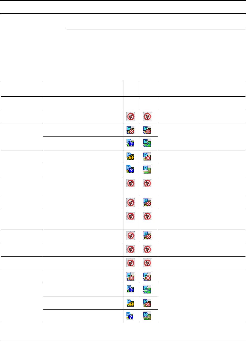
Help Hot Line (U.S. only): 1-800-530-9960 9-31
D-620003-0-20 Rev M CONFIDENTIAL
Troubleshooting CAT-5/5E/6
9.4 Troubleshooting CAT-5/5E/6
Refer to Table A-1 on page A-1 for a description of the CAT-5/5E/6 wire assignment.
The following table summarizes CAT-5/5E/6 problems if a wire is cut or not wired
properly.
Table 9-14 Summary of Cat-5/5E/6 Cable Wiring Problems
Type of
problem Message Icon Icon* Impact
Wire 1 or 2 cut None High phase noise, degraded signal on both
Downlink and Uplink (high bit error rate)
Wire 3 or 6 cut • No communication with RAUn RAU unable to communicate with EH,
decreased UL gain, or no UL gain
Wire 4 or 5 cut • Portn UL RF path loss is too high Increased ripple in the uplink path,
decreased UL gain, or no UL gain
• Portn UL RF path loss is higher
than recommended
Wire 7 or 8 cut • The DL RF path loss is too high Increased ripple in the downlink path,
RAU off-line
• The DL RF path loss is higher than
recommended
Wire 1 to RJ-45
pin 3 or 6 • No communication with RAUn RAU unable to communicate with EH,
RAU’s RS-485 port damaged, degraded
performance or RAU off-line
Wire 1 to RJ-45
pin 4, 5, 7 or 8 •RAUn over current RAU will not power on.
Wire 2 to RJ-45
pin 3 or 6 • No communication with RAUnRAU unable to communicate with EH,
RAU’s RS-485 port damaged, degraded
performance or RAU off-line
Wire 2 to RJ-45
pin 4, 5, 7 or 8 •RAUn over current RAU will not power on
Wire 3 to RJ-45
pin 4, 5, 7 or 8 • No communication with RAUnRAU unable to communicate with EH,
degraded performance or RAU off-line
Wire 6 to RJ-45
pin 4, 5, 7 or 8 • No communication with RAUnRAU unable to communicate with EH,
degraded performance or RAU off-line
Wire 4 to RJ-45
pin 7 or 8 • Portn UL RF path loss is too high Increased ripple in the downlink and
uplink path, degraded performance or
RAU off-line
• Portn UL RF path loss is higher
than recommended
• The DL RF path loss is too high
• The DL RF path loss is higher than
recommended
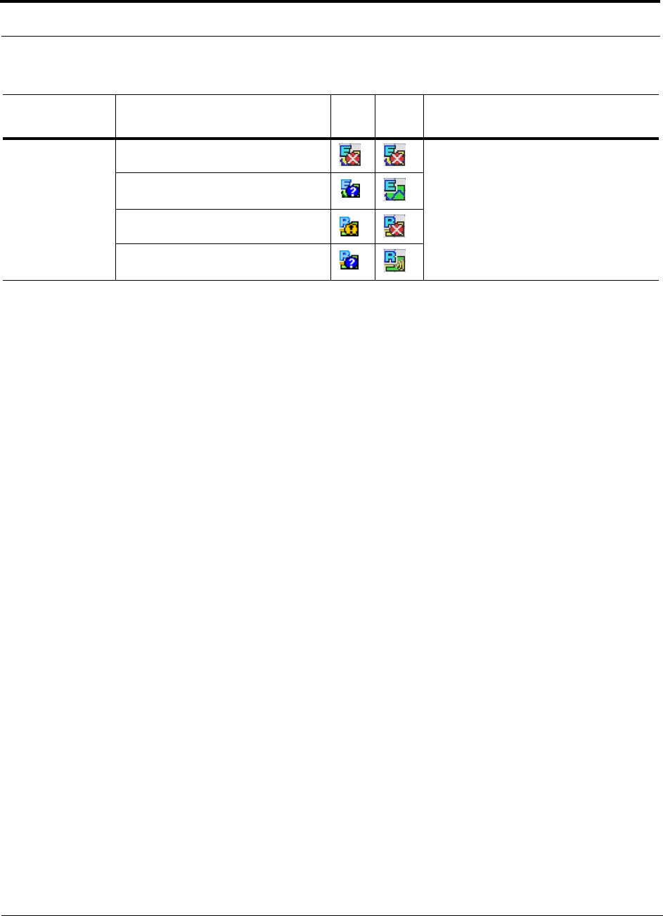
Troubleshooting CAT-5/5E/6
9-32 InterReach Unison Installation, Operation, and Reference Manual
CONFIDENTIAL D-620003-0-20 Rev M
Wire 5 to RJ-45
pin 7 or 8 • Portn UL RF path loss is too high Increased ripple in the downlink and
uplink path, degraded performance or
RAU off-line
• Portn UL RF path loss is higher
than recommended
• The DL RF path loss is too high
• The DL RF path loss is higher than
recommended
Table 9-14 Summary of Cat-5/5E/6 Cable Wiring Problems (continued)
Type of
problem Message Icon Icon* Impact

Help Hot Line (U.S. only): 1-800-530-9960 9-33
D-620003-0-20 Rev M CONFIDENTIAL
Technical Assistance
9.5 Technical Assistance
Call the ADC help hot line for technical assistance:
1-800-530-9960 (U.S. only)
+1-408-952-2400 (International)
Please provide your name, phone number, and e-mail address, along with the follow-
ing information. An ADC customer service representative will contact you with assis-
tance.
• Company name
• End user name
• Type of system, model number, frequency
• Approximate time in service (warranty), sales order number
• Description of problem
• LED status
• AdminManager faults, warnings, and status messages

Technical Assistance
9-34 InterReach Unison Installation, Operation, and Reference Manual
CONFIDENTIAL D-620003-0-20 Rev M
This page is intentionally left blank.

InterReach Unison Installation, Operation, and Reference Manual A-1
D-620003-0-20 Rev M CONFIDENTIAL
APPENDIX A Cables and Connectors
A.1 CAT-5E/6 Cable (ScTP)
• Connects the Expansion Hub to the RAU(s)
• Transmits (downlink) and receives (uplink) IF signals
• Delivers DC electrical power to the RAU(s). The Expansion Hub’s DC voltage
output is 36V DC nominal. A current limiting circuit is used to protect the Expan-
sion Hub if it reaches its current limit
• Carries configuration and status information
• Use shielded RJ-45 connectors
• Distances:
• Minimum: 10 meters (33 ft)
• Recommended Maximum: 100 meters (328 ft)
• Absolute Maximum: 150 meters (492 ft)
Refer to Cat-5/5E/6 Cabling Requirements for Unison Family Field Note (FN04-001)
for more information.
There are four separate twisted pairs in one CAT-5E/6 screened twisted pair (ScTP)
cable. The ScTP cable loss described in this document is for CAT-5 Belden 1624P
DataTwist Five cable, or equivalent. Table A-1 lists the functional assignment of the
pairs:
Table A-1 CAT-5E/6 Twisted Pair Assignment
Pair (wire number) Function
1 & 2 Clock and Input Voltage
3 & 6 RS-485
4 & 5 Uplink IF, UL Pilot and Ground
7 & 8 Downlink IF, DL Pilot and Ground
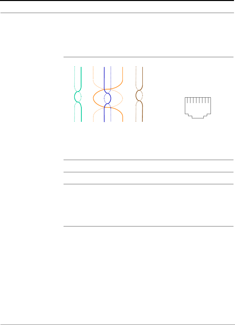
CAT-5E/6 Cable (ScTP)
A-2 InterReach Unison Installation, Operation, and Reference Manual
CONFIDENTIAL D-620003-0-20 Rev M
All CAT-5E/6 cable must be terminated according to the TIA/EIA 568-A standard.
Figure A-1 shows the top view of the wiring map for the cable and how the four pairs
should be terminated.
Figure A-1 Wiring Map for Cat-5E/6 Cable
The nominal DC impedance of the CAT-5E/6 cable is 0.08 ohm/meter and the nomi-
nal RF impedance is 100 ohm.
NOTE: Be sure to test cable termination before installing the cable.
NOTE: Belden 1624P DataTwist® Five ScTP cable, or equivalent is required.
Belden 1533P/R DataTwist® Five ScTP cable or equivalent is required for
CAT-5E. Additionally, Commscope 5ES4/5ENS4 may also be used for CAT-5E. In
order to meet FCC and CE Mark emissions requirements, the CAT-5/5E/6 cable
must be screened (ScTP) and it must be grounded to the units at both ends (that is,
RAU and Expansion Hub) using shielded RJ-45 connectors.
12 3 45 6 78
Brown
Brown/
White
Blue Blue/
White
Green/
White
Green Orange
Orange/
White
RJ-45 Port
12345678
W-G
G
W-O
BL
W-BL
O
W-BR
BR

Help Hot Line (U.S. only): 1-800-530-9960 A-3
D-620003-0-20 Rev M CONFIDENTIAL
Fiber Optical Cables
A.2 Fiber Optical Cables
• Connects the Main Hub to Expansion Hub(s)
• Transmits (downlink) and receives (uplink) optical signals
• Carries configuration and status information
• Use industry-standard 62.5µm/125µm MMF or Corning SMF-28 fiber, or equiva-
lent.
• SC/APC (angle-polished) connectors are required throughout the fiber network
(port-to-port), including fiber distribution panels
• Distances:
• Multi-mode Fiber: up to 1.5 km (4,921 ft) – 3 dB optical loss maximum
• Single-mode Fiber: up to 6 km (19,685 ft) – 3 dB optical loss maximum
A.3 Coaxial Cable
• Connects a Main Hub to a repeater or base station (N-type connectors)
• Connects an RAU to a passive antenna (SMA connectors)
A.4 Standard Modem Cable
• Connects a modem to the Main Hub’s front panel serial port
Figure A-2 Standard Modem Cable Pinout
DB-9
Connector
Pin
DB-25
Connector
Pin
1
2
3
4
5
6
7
8
9
8
3
2
20
7
6
4
5
22
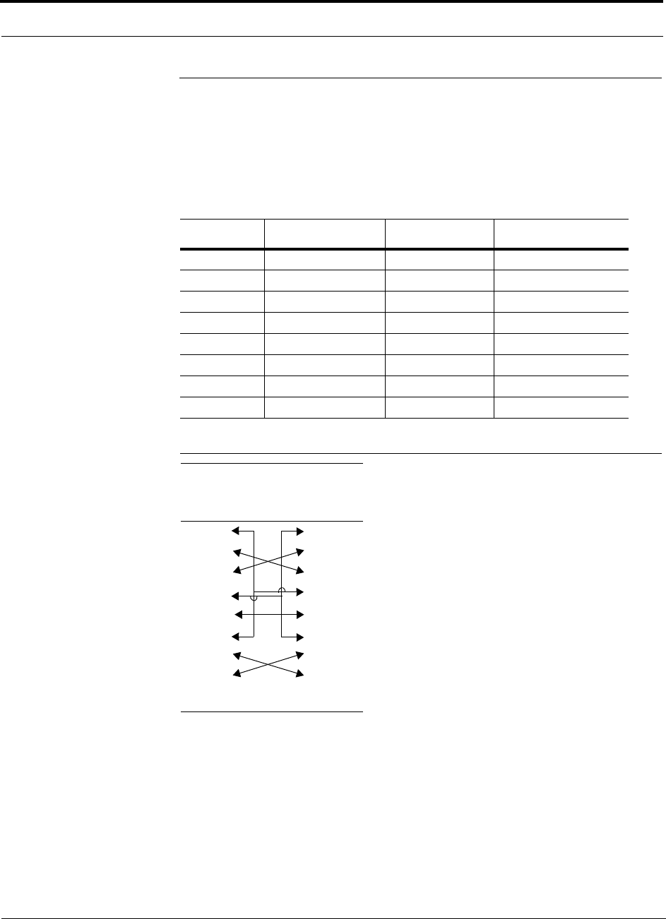
DB-9 to DB-9 Null Modem Cable
A-4 InterReach Unison Installation, Operation, and Reference Manual
CONFIDENTIAL D-620003-0-20 Rev M
A.5 DB-9 to DB-9 Null Modem Cable
Use a DB-9 female to DB-9 female null modem cable to connect the AdminManager
PC to a Unison Main Hub. A cable is included with AdminManager. Table A-2 lists
the cable pinout and Figure A-3 shows a diagram of its wiring.
Figure A-3 DB-9 Female to DB-9 Female Null Modem Cable Diagram
Table A-2 DB-9 Female to DB-9 Female Null Modem Cable Pinout
From Signal To Signal
P1-4 DTR P2-6, P2-1 DSR, DCD
P1-6 DSR P1-1, P2-4 DCD, DTR
P1-3 TXD P2-2 RXD
P1-2 RXD P2-3 TXD
P1-5 GND P2-5 GND
P1-7 RTS P2-8 CTS
P1-8 CTS P2-7 RTS
P1-9 N/C N/C N/C
Note that for each DB-9 connector, pins 1 and 6 are tied together and sent to pin 4
of the opposite connector, providing the required handshake signals.
DB-9
Connector
Pin
DB-9
Connector
Pin
1
2
3
4
5
6
7
8
9
1
2
3
4
5
6
7
8
9
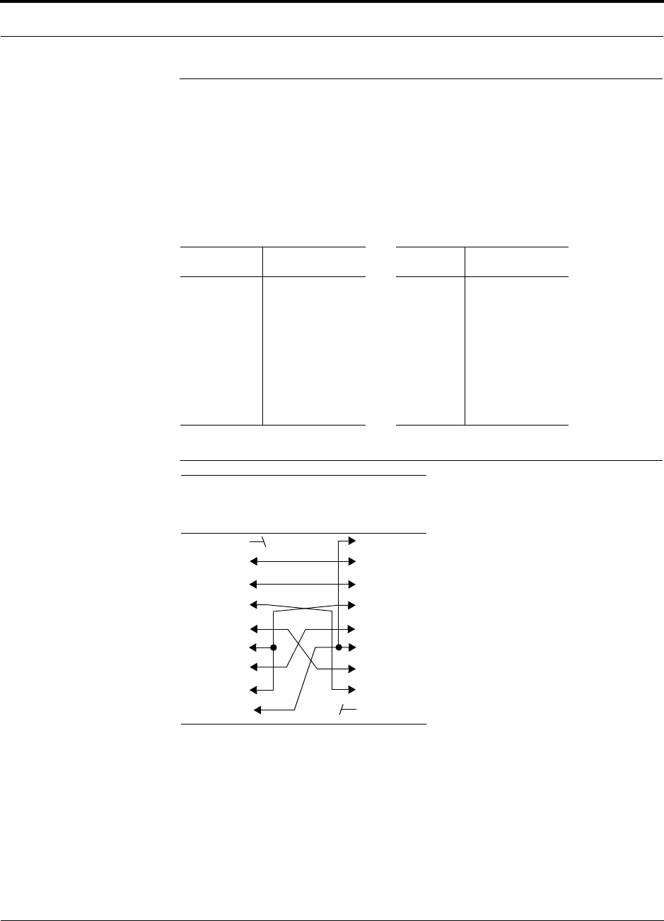
Help Hot Line (U.S. only): 1-800-530-9960 A-5
D-620003-0-20 Rev M CONFIDENTIAL
DB-25 to DB-9 Null Modem Cable
A.6 DB-25 to DB-9 Null Modem Cable
A DB-25 male to DB-9 female Null modem cable connects a 232 Port Expander to a
Unison Main Hub, or to connect a modem to the Main Hub when using OpsConsole
to monitor the system. Table A-3 lists the pinout of the cable for Unison and
Figure A-4 shows a diagram of its wiring.
Figure A-4 DB-25 Male to DB-9 Female Null Modem Cable Diagram
Table A-3 DB-25 Male to DB-9 Female Null Modem Cable Pinout
25-Pin Signal 9-Pin Signal
20
2
3
6,8
7
5
4
DTR
TX
RX
DSR, DCD
GND
CTS
RTS
1, 6
2
3
4
5
7
8
DSR, DCD
RX
TX
DTR
GND
RTS
CTS
DB-25 Male
Connector
Pin
DB-9 Female
Connector
Pin
1
2
3
4
5
6
7
8
20
1
2
3
4
5
6
7
8
9

DB-25 to DB-9 Null Modem Cable
A-6 InterReach Unison Installation, Operation, and Reference Manual
CONFIDENTIAL D-620003-0-20 Rev M
This page is intentionally left blank.

InterReach Unison Installation, Operation, and Reference Manual B-1
D-620003-0-20 Rev M CONFIDENTIAL
APPENDIX B Compliance
B.1 Unison System Approval Status
900 Paging/SMR
• Safety: UL 60950 3rd Edition
• EMC: FCC part 15 class A
• Radio: FCC Part 90
Cellular Products
• Safety: UL 60950 3rd Edition
• EMC: FCC part 15 class A
• Radio: FCC Part 22
DCS Products
• Safety: CB scheme evaluation to IEC 950, 3rd Edition with all national deviations
• EMC: EN 301 489-8 V.1.1.1 (2000-09), CISPR 24: 1998
• Radio: ETS 300 609-4 V.8.0.2 (2000-10)
GSM Products
• Safety: CB scheme evaluation to IEC 950, 3rd Edition with all national deviations
• Radio: EN 301 502 V.7.0.1 (2000-08)
• EMC: EN 301 489-8 V.1.1.1 (2000-09), CISPR 24: 1998

Unison System Approval Status
B-2 InterReach Unison Installation, Operation, and Reference Manual
CONFIDENTIAL D-620003-0-20 Rev M
iDEN Products
• Safety: UL 60950, 3rd Edition
• EMC: FCC part 15 class A
• Radio: FCC part 90
PCS Products
• Safety: UL 60950 3rd Edition
• EMC: FCC part 15 class A
• Radio: FCC part 24
• Radio: FCC part 22
UMTS Products
• Safety: CB scheme evaluation to IEC 950, 3rd Edition with all national deviations
• EMC: ETSI TS 125 113 V.4.1.0 (2001-06)
• Radio: ETSI TS 125 143 V.4.0.0 (2001-03)
AWS Products
• Safety: UL 60950 3rd Edition and 60950-1 1st Edition
• EMC: FCC part 15 class A
• Radio: FCC part 27
Public Safety 700 MHz Products
• Safety: UL, CSA, CB Scheme certificate to IEC 60950, 3rd Edition, and IEC
60950-1, 1st Edition, with all national deviations
• EMC: FCC part 15 class A
• Radio: FCC part 27
700 MHz LTE Products
• Safety: UL, CSA, CB Scheme certificate to IEC 60950, 3rd Edition, and IEC
60950-1, 1st Edition, with all national deviations
• EMC: FCC part 15 class A
• Radio: FCC part 27

Help Hot Line (U.S. only): 1-800-530-9960 B-3
D-620003-0-20 Rev M CONFIDENTIAL
Human Exposure to RF
NOTE: For Canadian customers, the Manufacturer’s rated output power1
of this equipment is for single carrier operation. For situations when multi-
ple carrier signals are present, the rating would have to be reduced by 3.5
dB, especially where the output signal is re-radiated and can cause interfer-
ence to adjacent band users. This power reduction is to be by means of input
power or gain reduction and not by an attenuator at the output of the device.
NOTE: This device complies with Part 15 of the FCC Rules. Operation is
subject to the following two conditions: (1) this device may not cause harm-
ful interference, and (2) this device must accept any interference received,
including interference that may cause undesired operation.
NOTE: This equipment has been tested and found to comply with the limits
for a Class A digital device, pursuant to Part 15 of the FCC Rules. These
limits are designed to provide reasonable protection against harmful interfer-
ence when the equipment is operated in a commercial environment. This
equipment generates, uses, and can radiate radio frequency energy and, if
not installed and used in accordance with the instruction manual, may cause
harmful interference to radio communications.
This equipment complies with the FCC radiation exposure limits for general popula-
tion/uncontrolled exposure environments.
Changes or modifications not approved and performed by ADC may void the user’s
authority to operate the equipment.
B.2 Human Exposure to RF
The U.S. Federal Communications Commission (FCC) has developed guidelines for
evaluation of human exposure to RF emissions. The guidelines incorporate limits for
Maximum Permissible Exposure (MPE) for power density of transmitters operating
at frequencies between 300 kHz and 100 GHz. Limits have been set for portable,
mobile, and fixed equipment. ADC products fall in the category of fixed equipment;
products intended to be permanently secured and exposures are evaluated for dis-
1. “Manufacturer’s rated output power” refers to Unison’s downlink P1dB. The power per carrier tables take into account this
power reduction for multiple carriers.

Human Exposure to RF
B-4 InterReach Unison Installation, Operation, and Reference Manual
CONFIDENTIAL D-620003-0-20 Rev M
tances greater than 20cm (7 7/8”). Portable devices fall into exposures of less than
20cm, are SAR evaluations are used.
Antenna gain is restricted to 1.5 W ERP (2.49 W EIRP) in order to satisfy RF expo-
sure compliance requirements. If higher than 1.5 W ERP, routine MPE evaluation is
needed. The antennas should be installed to provide at least 20 cm from all persons to
satisfy MPE requirements of FCC Part 2, 2.1091.
Basic MPE evaluation is performed by taking the maximum power output of the
equipment, the gain of the antenna to be used, and distance from the antenna, refer-
enced in FCC OET Bulletin 65 “Evaluation Compliance with FCC Guidelines for
Human Exposure to Radio Frequency for Electric Fields”.
ADC products transmit well below the FCC power density limits. FCC defines power
output limits at 20cm distance for various frequency ranges:
• Over 300 mHz to 1.5 GHz the limit is determined by frequency/1500
• Above 1.5 GHz the limit is 1mW/cm2
The basic equation for determining power density is:
S = PG / 4πR2
Where S is power density in mW/cm2
PG, the transmitted power from the antenna identified as EIRP (Equivalent Isotropi-
cally Radiated Power), is the product of power output of device and antenna gain, in
mW.
R is the distance of interest from the antenna.
Typical Installation Example:
Assuming an antenna is placed on a 10 foot ceiling, for a person 6 feet tall, the dis-
tance from antenna to body is 4 feet (112 cm.).
For a PCS 1900 or Cell 850 remote unit, the maximum power output, according to the
power table in Section 6.3 Maximum Output Power per Carrier on page 6-4, is 16.5
dB.
Assuming a 7 dBi antenna is used, PG in the equation is equal to 23.5 dB (224 mW)
EIRP.
Using S = PG/4πR2
S = 224/(4x3.14) x (122)2 = 0.001 mW/cm2
Also, assuming a minimum distance of 20 cm according to FCC regulations”
S = 224/(4 x 3.14) x (20)2 = 0.04 mW/cm2

InterReach Unison Installation, Operation, and Reference Manual C-1
D-620003-0-20 Rev M CONFIDENTIAL
APPENDIX C Changes and New Capabilities
To check the firmware version of any Unison component, launch AdminManager and
right-click on the component icon (main hub, expansion hub, or RAU) in the hierar-
chical tree. Select “Get Information” in the pull down menu.
ADC recommends that you use the latest firmware to optimize operations of your
Unison system. The latest firmware can be downloaded through the ADC Customer
Portal, accessible through our main website at www.adc.com.
C.1 New in Rev. M of Manual
• Support for Unison 700 MHz LTE band.
C.2 New in Rev. L of Manual
• Added reference to “Unison Release 5.8” Field Note (FN08-001).
C.3 New in Rev. K of Manual
• Support for 700 MHz Public Safety band
C.4 New in Rev. J of Manual
• Support for two new AWS bands

New in Rev. H. of Manual
C-2 InterReach Unison Installation, Operation, and Reference Manual
CONFIDENTIAL D-620003-0-20 Rev M
C.5 New in Rev. H. of Manual
• Supports scheduled system test.
• Supports 1 dB step attenuator and antenna disconnect in UMTS-2.
• Antenna disconnect alarm is user selectable between status and warning.
• Bookmarks for navigational ease
• Link to the ADC customer portal for on-line configuration tools and product com-
patibility information
• Supports UPS contact closure (UNS-EH-2 only) monitoring at the Expansion Hub
• Support for 4 new PCS bands
• New system configuration screen shot
• Updated Maintenance and troubleshooting section
C.6 New in Rev. G of Manual
• Ability to filter warnings and status messages
• Reclassification of some faults to warnings and some warnings to status messages.
Faults are service impacting. Warnings are possible service impacting. Status mes-
sages are internal states that could impact service but not at the current time.
C.7 New in Rev. F of Manual
• Added additional reference to Japan Specification Document
C.8 New in Rev. E of Manual
• Added reference to Japan Specification Document

Help Hot Line (U.S. only): 1-800-530-9960 C-3
D-620003-0-20 Rev M CONFIDENTIAL
New in Rev. D of Manual
C.9 New in Rev. D of Manual
• Supports 35 MHz PCS RAU
• Refer to “Unison Release 5.1” Field Note (FN03-007, formerly FN-024)
C.10 New in Rev. C of Manual
• Power per Carrier tables
• Removed DCS3
• EGSM is a subset of GSM
• Unison Cat-5 Extender added
• Dual-band Diplexer added
C.11 New in Rev. B of Manual
• Supports GSM and EGSM frequency bands using the GSM RAU
Frequencies: DL 1815–1850 MHz, UL 1720–1755 MHz
• Supports globally downloading firmware updates to multiple units at the same
time (that is, all RAUs in a system, then all of the Expansion Hubs, and finally the
Main Hub)
• Supports reclassification of status messages

New in Rev. B of Manual
C-4 InterReach Unison Installation, Operation, and Reference Manual
CONFIDENTIAL D-620003-0-20 Rev M
This page is intentionally left blank.

Help Hot Line (U.S. only): 1-800-530-9960 C-5
D-620003-0-20 Rev M CONFIDENTIAL
New in Rev. B of Manual

New in Rev. B of Manual
C-6 InterReach Unison Installation, Operation, and Reference Manual
CONFIDENTIAL D-620003-0-20 Rev M

InterReach Unison Installation, Operation, and Reference Manual D-1
D-620003-0-20 Rev M CONFIDENTIAL
APPENDIX D Glossary
Air Interface A method for formatting data and voice onto radio waves. Common
air interfaces include AMPS, TDMA, CDMA, and GSM.
AIN Advanced Intelligent Network. AINs allow a wireless user to make and receive
phone calls while roaming outside the user’s “home” network. These networks,
which rely on computers and sophisticated switching techniques, also provide
many Personal Communications Service (PCS) features.
Amplitude The distance between high and low points of a waveform or signal.
AMPS Advanced Mobile Phone Service. AMPS is an analog cellular FDMA sys-
tem. It was the basis of the first commercial wireless communication system in
the U.S and has been used in more than 35 other countries worldwide.
Analog The original method of modulating radio signals so they can carry informa-
tion which involves transmitting a continuously variable signal. Amplitude Mod-
ification (AM) and Frequency Modulation (FM) are the most common methods
of analog modulation.
ANSI The American National Standards Institute. A nonprofit, privately funded
membership organization founded in 1918 that reviews and approves standards
developed by other organizations.
AWS Advanced Wireless Services
Antenna A device for transmitting and/or receiving signals.
Attenuation The decrease in power that occurs when any signal is transmitted.
Attenuation is measured in decibels (dB).
Backhaul A term applied to the process of carrying wireless traffic between the
MSC and the base station.
Base Station The radio transmitter/receiver that maintains communications with
mobile devices within a specific area.

D-2 InterReach Unison Installation, Operation, and Reference Manual
CONFIDENTIAL D-620003-0-20 Rev M
BSC Base Station Controller. A GSM term referring to the device in charge of man-
aging the radio interface in a GSM system, including the allocation and release of
radio channels and hand-off of active calls within the system.
BTA Basic Trading Area. The U.S. and its territories are divided into 493 areas,
called BTAs. These BTAs are composed of a specific list of counties, based on a
system originally developed by Rand McNally. The FCC grants licenses to wire-
less operators to provide service within these BTAs and/or MTAs. (See MTA.)
BTS Base Transceiver Station. A GSM term referring to the group of network
devices that provide radio transmission and reception, including antennas.
C/I Carrier to interference ratio. The ratio of the desired signal strength to the com-
bined interference of all mobile phones using the system. Usually, the interfer-
ence of most concern is that provided by mobile phones using the same channel
in the system. These are referred to as “co-channel interferers.”
CCITT Consultative Committee on International Telephone and Telegraph. This
organization sets international communications standards. The CCITT is now
known as ITU (the parent organization).
CDMA Code Division Multiple Access. A digital wireless access technology that
uses spread-spectrum techniques. Unlike alternative systems, such as GSM, that
use time-division multiplexing (TDM), CDMA does not assign a specific fre-
quency to each user. Instead, every channel uses the full available spectrum. Indi-
vidual conversations are assigned a unique code which allows the conversation
to be spread out over multiple channels; transmitted to the far end; and re-assem-
bled for the recipient using a specific code.
CDPD Cellular Digital Packet Data. CDPD allows data transmission over the ana-
log wireless network. CDPD breaks data into packets and transmits these packets
on idle portions of the network.
Cell A cell defines a specific, physical area of coverage of a portion of a wireless
system. It is the basic “building block” of all modern wireless communications
systems.
Cell Site A term which refers to the location of the transmission equipment (e.g.,
basestation) within the cell.
CEPT Conference of European Postal and Telecommunications Administrations.
This organization’s mandate is to define pan-European wireless communications
standards. In 1982, CEPT mandated GSM as the access protocol for public wire-
less communications systems across Europe.
Channel The path along which a communications signal is transmitted. Channels
may be simplex (communication occurs in only one direction), duplex (commu-
nication occurs in both directions) or full duplex (communication occurs in both
directions simultaneously).

InterReach Unison Installation, Operation, and Reference Manual D-3
D-620003-0-20 Rev M CONFIDENTIAL
Circuit A communication connection between two or more points. A circuit can
transmit either voice or data.
CO Central Office. The main switching facility for a telecommunications system.
CTIA Cellular Telecommunications Industry Association. The CTIA is an industry
association made up of most of the wireless carriers and other industry players. It
was formed in 1984 to promote the cellular industry and cellular technology.
D-AMPS Digital Advanced Mobile Phone Service. See IS-54.
dB Decibel. A unit for expressing the ratio of two amounts of power. It is often used
in wireless to describe the amount of power loss in a system (i.e., the ratio of
transmitted power to received power).
DCS Digital Communications System. DCS is often called “upbanded GSM” since
it is the GSM access scheme adopted to operate in the 1700–1800 MHz portion
of the spectrum.
Digital A method of storing, processing, and transmitting information by represent-
ing information as “0s” and “1s” via electrical pulses. Digital systems have
largely replaced analog systems because they can carry more data at higher speed
than analog transmission systems.
Electromagnetic Spectrum Electrical wave forms in frequency ranges as low as
535 kHz (AM radio) and as high as 29 GHz (cable TV).
ESMR Enhanced Specialized Mobile Radio. Digital mobile telephone services
offered to the public over channels previously used for two-way analog dispatch
services. ESMR provides digital mobile radio and telephone service as well as
messaging and dispatch features.
ETSI European Telecommunications Standards Institute. ETSI was established in
1988 to set standards for Europe in telecommunications, broadcasting and office
information technology.
FCC Federal Communications Commission. In the United States, the FCC is
responsible for the management and regulation of communication policy for all
public communications services, including wireless.
FDMA Frequency Division Multiple Access. A wireless access protocol that
assigns each user a specific radio channel for use. Since FDMA only supports
one user (or conversation) on each channel, it does not maximize use of the spec-
trum and is therefore largely been superseded by other access protocols (such as
CDMA, TDMA, GSM, iDEN) that support multiple users on a single channel.
Frequency Hopping A wireless signal transmission technique whereby the fre-
quency used to carry a signal is periodically changed, according to a predeter-
mined code, to another frequency.

D-4 InterReach Unison Installation, Operation, and Reference Manual
CONFIDENTIAL D-620003-0-20 Rev M
Fixed An ITU definition for radio communications between specified fixed points.
Point-to-point high-frequency circuits and microwave links are two examples of
fixed applications.
FM Frequency Modulation. A method of transmitting information in which the fre-
quency of the carrier is modified according to a plan agreed to by the transmitter
and the receiver. FM can be either analog or digital.
Forward Channel Refers to the radio channel that sends information from the base
station to the mobile station. (See Reverse Channel.)
Frequency The number of times an electrical signal repeats an identical cycle in a
unit of time, normally one second. One Hertz (Hz) is one cycle per second.
Frequency re-use The ability to use the same frequencies repeatedly across a cellu-
lar system. Because each cell is designed to use radio frequencies only within its
boundaries, the same frequencies can be reused in other cells not far away with
little potential for interference. The reuse of frequencies is what enables a cellu-
lar system to handle a huge number of calls with a limited number of channels.
Gain The increase in power that occurs when any signal is amplified, usually
through an amplifier or antenna.
GHz Gigahertz. A measure of frequency equal to one billion hertz.
GSM Groupe Speciale Mobile (now translated in English as Global Standard for
Mobile Communications). GSM is the digital wireless standard used throughout
Europe, in much of Asia, as well as by some operators in the U.S. and South
America.
Handoff The process by which the wireless system passes a wireless phone conver-
sation from one radio frequency in one cell to another radio frequency in another
as the caller moves between two cells. In most systems today, this handoff is per-
formed so quickly that callers don’t notice.
Hertz A measurement of electromagnetic energy, equivalent to one “wave” per sec-
ond. Hertz is abbreviated as “Hz”.
iDEN Integrated Digital Enhanced Network. A TDMA-based wireless access tech-
nology that combines two-way radio, telephone, text message, and data transmis-
sion into one network. This system was developed by Motorola. In the U.S.,
iDEN is used by Nextel in its network.
IEEE The Institute of Electrical and Electronics Engineers. The world’s largest
technical professional society with members from more than 130 countries. The
IEEE works to advance the theory and practice of electrical, electronics, com-
puter engineering and computer science.
Infrastructure A term used to encompass all of the equipment, including both hard-
ware and software, used in a communications network.

InterReach Unison Installation, Operation, and Reference Manual D-5
D-620003-0-20 Rev M CONFIDENTIAL
IS-54 Interim Standard-54. A U.S. TDMA cellular standard that operates in the
800 MHz or 1900 MHz band. IS-54 was the first U.S. digital cellular standard. It
was adopted by the CTIA in 1990.
IS-95 Interim Standard-95. A U.S. CDMA cellular standard that operates in the
800 MHz or 1900 MHz band. This standard was developed by Qualcomm and
adopted by the CTIA in 1993.
IS-136 Interim Standard-136. A U.S. TDMA cellular standard based on IS-54 that
operates in the 800 MHz or 1900 MHz band.
IS-553 Interim Standard-533. The U.S. analog cellular (AMPS) air interface stan-
dard.
ITU International Telecommunications Union. The ITU is the principal interna-
tional standards organization. It is charted by the United Nations and it estab-
lishes international regulations governing global telecommunications networks
and services. Its headquarters are in Geneva, Switzerland.
LMDS Local Multipoint Distribution Services. LMDS provides line-of-sight cover-
age over distances up to 3–5 kilometers and operates in the 28 GHz portion of the
spectrum. It can deliver high speed, high bandwidth services such as data and
video applications.
Local Loop A communication channel (usually a physical phone line) between a
subscriber’s location and the network’s Central Office.
LTE Long Term Evolution.
MHz Megahertz. One million Hertz. One MHz equals one million cycles per sec-
ond.
Microcell A network cell designed to serve a smaller area than larger macrocells.
Microcells are smaller and lower powered than macrocells. As the subscriber
base increases, operators must continue to increase the number of cells in their
network to maximize channel re-use. This has led to an increasing number of
microcells being deployed in wireless networks.
Microwave Electromagnetic waves with frequencies above 1 GHz. Microwave
communications are used for line-of-sight, point-to-point, or point-to-multipoint
communications.
MSA Metropolitan Statistical Area. The FCC has established 306 MSAs in the U.S.
The MSAs represent the largest population centers in the U.S. At least two wire-
less operators are licensed in each MSA.
MSC Mobile Services Switching Center. A generic term for the main cellular
switching center in the wireless communications network.
MSS Mobile Satellite Service. Communications transmission service provided by
satellites. A single satellite can provide coverage to the entire United States.

D-6 InterReach Unison Installation, Operation, and Reference Manual
CONFIDENTIAL D-620003-0-20 Rev M
MTA Major Trading Area. The U.S. and its territories are divided into 51 MTAs.
Each MTA is composed of a specific number of BTAs. The FCC grants licenses
to wireless operators to provide service within these MTAs and/or BTAs. (See
BTA.)
Multiplexing The simultaneous transmission of two or more signals on the same
radio (or other) transmission facility.
N-AMPS Narrowband Advanced Mobile Phone Service.
PCMCIA Personal Computer Memory Card International Association. This acro-
nym is used to refer to credit card sized packages containing memory, I/O
devices and other capabilities for use in Personal Computers, handheld comput-
ers and other devices.
PCS Personal Communications Service. A vague label applied to new-generation
mobile communication technology that uses the narrow band and broadband
spectrum recently allocated in the 1.9 GHz band.
PDA Personal Digital Assistant. Portable computing devices that are extremely por-
table and that offer a variety of wireless communication capabilities, including
paging, electronic mail, stock quotations, handwriting recognition, facsimile, cal-
endar, and other information handling capabilities.
PDC Personal Digital Cellular (formerly Japanese Digital Cellular). A
TDMA-based digital cellular standard that operates in the 1500 MHz band.
Phase The particular angle of inflection of a wave at a precise moment in time. It is
normally measured in terms of degrees.
PHS Personal Handyphone System. A wireless telephone standard, developed and
first deployed in Japan. It is a low mobility, small-cell system.
POP Short for “population”. One person equals one POP.
POTS Plain Old Telephone Service.
POTS Plain Old Telephone Service.
PS Public Safety.
Reverse Channel Refers to the radio channel that sends information from a mobile
station to a base station. (See Forward Channel.)
RF Radio Frequency. Those frequencies in the electromagnetic spectrum that are
associated with radio wave propagation.
Roaming The ability to use a wireless phone to make and receive calls in places
outside one's home calling area.
RSA Rural Service Area. One of the 428 FCC-designated rural markets across the
United States used as license areas for cellular licenses. (See MTAs and BTAs.)

InterReach Unison Installation, Operation, and Reference Manual D-7
D-620003-0-20 Rev M CONFIDENTIAL
Sector A portion of a cell. Often, different sectors within the same cell will each use
a different set of frequencies to maximize spectrum utilization.
Signal to Noise Ratio The ratio of signal power to noise power at a given point in a
given system.
Smart Antenna Refers to an antenna whose signal handling characteristics change
as signal conditions change.
Soft Handoff Virtually undetectable by the user, soft handoff allows both the origi-
nal cell and a new cell to serve a call temporarily during the handoff transition.
Spectrum The range of electromagnetic frequencies.
Spread Spectrum A method of transmitting a signal over a broad range of frequen-
cies and then re-assembling the transmission at the far end. This technique
reduces interference and increases the number of simultaneous conversations
within a given radio frequency band.
T-1 A North American commercial digital transmission standard. A T-1 connection
uses time division multiplexing to carry 24 digital voice or data channels over
copper wire.
TDMA Time Division Multiple Access. A method of digital wireless communica-
tions that allows multiple users to access (in sequence) a single radio frequency
channel without interference by allocating unique time slots to each user within
each channel.
TIA Telecommunications Industry Association.
TR-45 One of six committees of the Telecommunications Industry Association.
TR-45 oversees the standard making process for wireless telecommunications.
Upbanded A service or technology that has been re-engineered to operate at a
higher frequency than originally designed.
Wireless Describes any radio-based system that allows transmission of voice and/or
data signals through the air without a physical connection, such as a metal wire
or fiber optic cable.
Wireline Wire paths that use metallic conductors to provide electrical connections
between components of a system, such as a communication system.
WLANs Wireless Local Area Networks. Technology that provides wireless com-
munications to Portable Computer users over short distances.

D-8 InterReach Unison Installation, Operation, and Reference Manual
CONFIDENTIAL D-620003-0-20 Rev M
This page is intentionally left blank.