ADC Telecommunications UNS-CELL-2 Cellular In-building Distributed Antenna Systems User Manual accel
ADC Telecommunications Inc. Cellular In-building Distributed Antenna Systems accel
Contents
- 1. User Manual 1 of 2
- 2. User Manual 2 of 2
User Manual 1 of 2
PN 9000-10
620021-0 Rev. A
Installation, Operation, and Reference Manual
InterReach Unison Accel
®

InterReach Unison Accel Installation, Operation, and Reference Manual PN 9000-10
620021-0 Rev. A
This manual is produced for use by LGC Wireless personnel, licensees, and customers. The
information contained herein is the property of LGC Wireless. No part of this document
may be reproduced or transmitted in any form or by any means, electronic or mechanical,
for any purpose, without the express written permission of LGC Wireless.
LGC Wireless reserves the right to make changes, without notice, to the specifications and
materials contained herein, and shall not be responsible for any damages caused by reliance
on the material as presented, including, but not limited to, typographical and listing errors.
Your comments are welcome – they help us improve our products and documentation.
Please address your comments to LGC Wireless, Inc. corporate headquarters in San Jose,
California:
Address 2540 Junction Avenue
San Jose, California
95134-1902 USA
Attn: Marketing Dept.
Phone 1-408-952-2400
Fax 1-408-952-2410
Help Hot Line 1-800-530-9960 (U.S. only)
+1-408-952-2400 (International)
Web Address http://www.lgcwireless.com
e-mail info@lgcwireless.com
service@lgcwireless.com
Copyright © 2002 by LGC Wireless, Inc. Printed in USA. All rights reserved.
Trademarks
All trademarks identified by ™ or ® are trademarks or registered trademarks of LGC
Wireless, Inc. All other trademarks belong to their respective owners.

PN 9000-10 InterReach Unison Accel Installation, Operation, and Reference Manual
620021-0 Rev. A
Limited Warranty
Seller warrants articles of its manufacture against defective materials or workmanship for a
period of one year from the date of shipment to Purchaser, except as provided in any warranty
applicable to Purchaser on or in the package containing the Goods (which warranty takes
precedence over the following warranty). The liability of Seller under the foregoing warranty
is limited, at Seller’s option, solely to repair or replacement with equivalent Goods, or an
appropriate adjustment not to exceed the sales price to Purchaser, provided that (a) Seller is
notified in writing by Purchaser, within the one year warranty period, promptly upon
discovery of defects, with a detailed description of such defects, (b) Purchaser has obtained a
Return Materials Authorization (RMA) from Seller, which RMA Seller agrees to provide
Purchaser promptly upon request, (c) the defective Goods are returned to Seller,
transportation and other applicable charges prepaid by the Purchaser, and (d) Seller’s
examination of such Goods discloses to its reasonable satisfaction that defects were not
caused by negligence, misuse, improper installation, improper maintenance, accident or
unauthorized repair or alteration or any other cause outside the scope of Purchaser’s warranty
made hereunder. Notwithstanding the foregoing, Seller shall have the option to repair any
defective Goods at Purchaser’s facility. The original warranty period for any Goods that have
been repaired or replaced by seller will not thereby be extended. In addition, all sales will be
subject to standard terms and conditions on the sales contract.

InterReach Unison Accel Installation, Operation, and Reference Manual PN 9000-10
620021-0 Rev. A

PN 9000-10 InterReach Unison Accel Installation, Operation, and Reference Manual i
620021-0 Rev. A
Table of Contents
SECTION 1 General Information . . . . . . . . . . . . . . . . . . . . . . 1-1
1.1 Purpose and Scope . . . . . . . . . . . . . . . . . . . . . . . . . . . . . . . . . 1-2
1.2 Conventions in this Manual . . . . . . . . . . . . . . . . . . . . . . . . . . 1-4
1.3 Acronyms in this Manual . . . . . . . . . . . . . . . . . . . . . . . . . . . . 1-5
1.4 Standards Conformance . . . . . . . . . . . . . . . . . . . . . . . . . . . . . 1-7
1.5 Related Publications . . . . . . . . . . . . . . . . . . . . . . . . . . . . . . . . 1-7
SECTION 2 InterReach Unison Accel System Description . 2-1
2.1 System Hardware Description . . . . . . . . . . . . . . . . . . . . . . . . 2-3
2.2 System OA&M Capabilities Overview . . . . . . . . . . . . . . . . . 2-4
2.2.1 System Monitoring and Reporting . . . . . . . . . . . . . . . . . . . . . 2-5
2.2.2 Using Alarm Contact Closures . . . . . . . . . . . . . . . . . . . . . . . . 2-5
2.3 System Connectivity . . . . . . . . . . . . . . . . . . . . . . . . . . . . . . . . 2-6
2.4 System Operation . . . . . . . . . . . . . . . . . . . . . . . . . . . . . . . . . . 2-7
2.5 System Specifications . . . . . . . . . . . . . . . . . . . . . . . . . . . . . . . 2-8
2.5.1 Physical Specifications . . . . . . . . . . . . . . . . . . . . . . . . . . . . . . 2-8
2.5.2 Environmental Specifications . . . . . . . . . . . . . . . . . . . . . . . . . 2-8
2.5.3 Operating Frequencies . . . . . . . . . . . . . . . . . . . . . . . . . . . . . . . 2-9
2.5.4 RF End-to-End Performance . . . . . . . . . . . . . . . . . . . . . . . . . 2-10
SECTION 3 Accel Hub . . . . . . . . . . . . . . . . . . . . . . . . . . . . . . 3-1
3.1 Accel Hub Front Panel . . . . . . . . . . . . . . . . . . . . . . . . . . . . . . 3-2
3.1.1 RJ-45 Connectors . . . . . . . . . . . . . . . . . . . . . . . . . . . . . . . . . . 3-3
3.1.2 Communications RS-232 Serial Connector . . . . . . . . . . . . . . 3-3
3.1.3 Hub LED Indicators . . . . . . . . . . . . . . . . . . . . . . . . . . . . . . . . 3-4
3.2 Accel Hub Rear Panel . . . . . . . . . . . . . . . . . . . . . . . . . . . . . . . 3-6
3.2.1 Accel Hub Rear Panel Connectors . . . . . . . . . . . . . . . . . . . . . 3-7
3.3 Faults and Warnings . . . . . . . . . . . . . . . . . . . . . . . . . . . . . . . . 3-8
3.4 Accel Hub Specifications . . . . . . . . . . . . . . . . . . . . . . . . . . . . 3-9

ii InterReach Unison Accel Installation, Operation, and Reference Manual PN 9000-10
620021-0 Rev. A
SECTION 4 Unison Remote Access Unit . . . . . . . . . . . . . . . 4-1
4.1 Remote Access Unit Connectors . . . . . . . . . . . . . . . . . . . . . . . 4-3
4.1.1 SMA Connector . . . . . . . . . . . . . . . . . . . . . . . . . . . . . . . . . . . . 4-3
4.1.2 RJ-45 Connector . . . . . . . . . . . . . . . . . . . . . . . . . . . . . . . . . . . 4-3
4.2 RAU LED Indicators . . . . . . . . . . . . . . . . . . . . . . . . . . . . . . . 4-4
4.3 Faults and Warnings . . . . . . . . . . . . . . . . . . . . . . . . . . . . . . . . 4-5
4.4 Remote Access Unit Specifications . . . . . . . . . . . . . . . . . . . . 4-5
4.5 RAUs in a Dual Band System . . . . . . . . . . . . . . . . . . . . . . . . . 4-6
SECTION 5 Designing a Unison Accel Solution . . . . . . . . . 5-1
5.1 Maximum Output Power per Carrier at RAU . . . . . . . . . . . . . 5-3
5.2 Estimating RF Coverage . . . . . . . . . . . . . . . . . . . . . . . . . . . . 5-17
5.2.1 Path Loss Equation . . . . . . . . . . . . . . . . . . . . . . . . . . . . . . . . 5-18
5.2.2 Coverage Distance . . . . . . . . . . . . . . . . . . . . . . . . . . . . . . . . . 5-19
5.2.3 Examples of Design Estimates . . . . . . . . . . . . . . . . . . . . . . . 5-24
5.3 System Gain . . . . . . . . . . . . . . . . . . . . . . . . . . . . . . . . . . . . . 5-28
5.3.1 System Gain (Loss) Relative to ScTP Cable Length . . . . . . . 5-28
5.4 Link Budget Analysis . . . . . . . . . . . . . . . . . . . . . . . . . . . . . . 5-29
5.4.1 Elements of a Link Budget for Narrowband Standards . . . . . 5-30
5.4.2 Narrowband Link Budget Analysis for a Microcell
Application . . . . . . . . . . . . . . . . . . . . . . . . . . . . . . . . . . . . . . 5-32
5.4.3 Elements of a Link Budget for CDMA Standards . . . . . . . . . 5-34
5.4.4 Spread Spectrum Link Budget Analysis for a Microcell
Application . . . . . . . . . . . . . . . . . . . . . . . . . . . . . . . . . . . . . . 5-37
5.4.5 Considerations for Re-Radiation (over-the-air) Systems . . . . 5-41
5.5 Connecting a Main Hub to a Base Station . . . . . . . . . . . . . . 5-42
5.5.1 Attenuation . . . . . . . . . . . . . . . . . . . . . . . . . . . . . . . . . . . . . . 5-43
5.5.2 Uplink Attenuation . . . . . . . . . . . . . . . . . . . . . . . . . . . . . . . . 5-44
5.6 Designing for a Neutral Host System . . . . . . . . . . . . . . . . . . 5-46
SECTION 6 Installing Unison Accel . . . . . . . . . . . . . . . . . . . . 6-1
6.1 Installation Requirements . . . . . . . . . . . . . . . . . . . . . . . . . . . . 6-1
6.1.1 Component Location Requirements . . . . . . . . . . . . . . . . . . . . 6-1
6.1.2 Cable and Connector Requirements . . . . . . . . . . . . . . . . . . . . 6-1
6.1.3 Multiple Operator System Recommendations . . . . . . . . . . . . . 6-2
6.1.4 Distance Requirements . . . . . . . . . . . . . . . . . . . . . . . . . . . . . . 6-2
6.2 Safety Precautions . . . . . . . . . . . . . . . . . . . . . . . . . . . . . . . . . . 6-3
6.2.1 Installation Guidelines . . . . . . . . . . . . . . . . . . . . . . . . . . . . . . . 6-3
6.2.2 General Safety Precautions . . . . . . . . . . . . . . . . . . . . . . . . . . . 6-3
6.3 Preparing for System Installation . . . . . . . . . . . . . . . . . . . . . . 6-4
6.3.1 Pre-Installation Inspection . . . . . . . . . . . . . . . . . . . . . . . . . . . . 6-4
6.3.2 Installation Checklist . . . . . . . . . . . . . . . . . . . . . . . . . . . . . . . . 6-5
6.3.3 Tools and Materials Required . . . . . . . . . . . . . . . . . . . . . . . . . 6-7
6.3.4 Optional Accessories . . . . . . . . . . . . . . . . . . . . . . . . . . . . . . . . 6-7
6.4 Unison Accel Installation Procedures . . . . . . . . . . . . . . . . . . . 6-8

PN 9000-10 InterReach Unison Accel Installation, Operation, and Reference Manual iii
620021-0 Rev. A
6.4.1 Installing an Accel Hub . . . . . . . . . . . . . . . . . . . . . . . . . . . . . 6-10
6.4.2 Installing RAUs . . . . . . . . . . . . . . . . . . . . . . . . . . . . . . . . . . . 6-15
6.4.3 Installing Dual Band RAU Configuration . . . . . . . . . . . . . . . 6-17
6.4.4 Installing Cat-5 Extender . . . . . . . . . . . . . . . . . . . . . . . . . . . . 6-19
6.4.5 Configuring the System . . . . . . . . . . . . . . . . . . . . . . . . . . . . . 6-20
6.5 Interfacing an Accel Hub to a Base Station or a Roof-top
Antenna . . . . . . . . . . . . . . . . . . . . . . . . . . . . . . . . . . . . . . . . . 6-21
6.5.1 Connecting Multiple Accel Hubs . . . . . . . . . . . . . . . . . . . . . 6-25
6.6 Connecting Contact Alarms to an Accel System . . . . . . . . . 6-29
6.6.1 Alarm Source . . . . . . . . . . . . . . . . . . . . . . . . . . . . . . . . . . . . . 6-30
6.6.2 Alarm Sense . . . . . . . . . . . . . . . . . . . . . . . . . . . . . . . . . . . . . 6-33
6.6.3 Alarm Cables . . . . . . . . . . . . . . . . . . . . . . . . . . . . . . . . . . . . . 6-34
6.7 Alarm Monitoring Connectivity Options . . . . . . . . . . . . . . . 6-36
6.7.1 Direct Connection . . . . . . . . . . . . . . . . . . . . . . . . . . . . . . . . . 6-36
6.7.2 Modem Connection . . . . . . . . . . . . . . . . . . . . . . . . . . . . . . . . 6-37
6.7.3 232 Port Expander Connection . . . . . . . . . . . . . . . . . . . . . . . 6-38
6.7.4 POTS Line Sharing Switch Connection . . . . . . . . . . . . . . . . 6-39
6.7.5 Ethernet and ENET/232 Serial Hub Connection . . . . . . . . . . 6-40
SECTION 7 Replacing Unison Accel Components in an
Operational System . . . . . . . . . . . . . . . . . . . . . . 7-1
7.1 Replacing an RAU . . . . . . . . . . . . . . . . . . . . . . . . . . . . . . . . . 7-1
7.2 Replacing an Accel Hub . . . . . . . . . . . . . . . . . . . . . . . . . . . . . 7-3
SECTION 8 Maintenance, Troubleshooting, and Technical
Assistance . . . . . . . . . . . . . . . . . . . . . . . . . . . . . . 8-1
8.1 Service . . . . . . . . . . . . . . . . . . . . . . . . . . . . . . . . . . . . . . . . . . 8-1
8.2 Maintenance . . . . . . . . . . . . . . . . . . . . . . . . . . . . . . . . . . . . . . 8-1
8.3 Troubleshooting . . . . . . . . . . . . . . . . . . . . . . . . . . . . . . . . . . . 8-2
8.3.1 Troubleshooting using AdminManager . . . . . . . . . . . . . . . . . . 8-3
8.3.2 Troubleshooting using LEDs . . . . . . . . . . . . . . . . . . . . . . . . . 8-10
8.4 Troublshooting Cat-5/6 . . . . . . . . . . . . . . . . . . . . . . . . . . . . . 8-13
8.5 Technical Assistance . . . . . . . . . . . . . . . . . . . . . . . . . . . . . . . 8-15
A.1 Cat-5/6 Cable (ScTP) . . . . . . . . . . . . . . . . . . . . . . . . . . . . . . . A-1
A.2 Coaxial Cable . . . . . . . . . . . . . . . . . . . . . . . . . . . . . . . . . . . . . A-2
A.3 Standard Modem Cable . . . . . . . . . . . . . . . . . . . . . . . . . . . . . A-3
A.4 DB-9 to DB-9 Null Modem Cable . . . . . . . . . . . . . . . . . . . . . A-4
A.5 DB-25 to DB-9 Null Modem Cable . . . . . . . . . . . . . . . . . . . . A-5
C.1 Unison System Approval Status . . . . . . . . . . . . . . . . . . . . . . . C-1
C.2 Human Exposure to RF . . . . . . . . . . . . . . . . . . . . . . . . . . . . . C-3
D.1 Unison Accel Release 5 . . . . . . . . . . . . . . . . . . . . . . . . . . . . . D-1

iv InterReach Unison Accel Installation, Operation, and Reference Manual PN 9000-10
620021-0 Rev. A

PN 9000-10 InterReach Unison Accel Installation, Operation, and Reference Manual v
620021-0 Rev. A
List of Figures
Figure 2-1 Unison Accel System Hardware . . . . . . . . . . . . . . . . . . . . . . . . . . . . . . 2-3
Figure 2-2 Three Methods for OA&M Communications . . . . . . . . . . . . . . . . . . . . 2-4
Figure 2-3 Unison Accel’s Architecture . . . . . . . . . . . . . . . . . . . . . . . . . . . . . . . . . 2-6
Figure 3-1 Accel Hub in a Unison System . . . . . . . . . . . . . . . . . . . . . . . . . . . . . . . 3-1
Figure 3-2 Accel Hub Block Diagram . . . . . . . . . . . . . . . . . . . . . . . . . . . . . . . . . . . 3-1
Figure 3-3 Accel Hub Front Panel . . . . . . . . . . . . . . . . . . . . . . . . . . . . . . . . . . . . . . 3-2
Figure 3-4 Accel Hub Rear Panel . . . . . . . . . . . . . . . . . . . . . . . . . . . . . . . . . . . . . . 3-6
Figure 4-1 Remote Access Unit in a Unison Accel System . . . . . . . . . . . . . . . . . . 4-1
Figure 4-2 Remote Access Unit Block Diagram . . . . . . . . . . . . . . . . . . . . . . . . . . . 4-2
Figure 5-1 Determining Path Loss between the Antenna and the Wireless Device 5-17
Figure 5-2 Connecting Main Hubs to a Simplex Base Station . . . . . . . . . . . . . . . 5-43
Figure 5-3 Main Hub to Duplex Base Station or Repeater Connections . . . . . . . . 5-44
Figure 6-1 Dual Band RAU Configuration . . . . . . . . . . . . . . . . . . . . . . . . . . . . . . 6-17
Figure 6-2 Simplex Base Station to an Accel Hub . . . . . . . . . . . . . . . . . . . . . . . . 6-21
Figure 6-3 Duplex Base Station to an Accel Hub . . . . . . . . . . . . . . . . . . . . . . . . . 6-22
Figure 6-4 Connecting an Accel Hub to Multiple Base Stations . . . . . . . . . . . . . . 6-23
Figure 6-5 Connecting Two Accel Hubs to a Simplex Repeater or Base Station . 6-26
Figure 6-6 Connecting Two Accel Hubs to a Duplex Repeater or Base Station . . 6-28
Figure 6-7 Connecting MetroReach to Unison Accel . . . . . . . . . . . . . . . . . . . . . . 6-30
Figure 6-8 Using a BTS to Monitor Unison Accel . . . . . . . . . . . . . . . . . . . . . . . . 6-31
Figure 6-9 Using a BTS and AdminManager to Monitor Unison Accel . . . . . . . . 6-32
Figure 6-10 Connecting LGCell to Unison Accel . . . . . . . . . . . . . . . . . . . . . . . . . . 6-33
Figure 6-11 5-port Alarm Daisy-Chain Cable . . . . . . . . . . . . . . . . . . . . . . . . . . . . . 6-34
Figure 6-12 Alarm Sense Adapter Cable . . . . . . . . . . . . . . . . . . . . . . . . . . . . . . . . . 6-35
Figure 6-13 OA&M Direct Connection . . . . . . . . . . . . . . . . . . . . . . . . . . . . . . . . . . 6-36
Figure 6-14 OA&M Modem Connection . . . . . . . . . . . . . . . . . . . . . . . . . . . . . . . . 6-37
Figure 6-15 OA&M Connection using a 232 Port Expander . . . . . . . . . . . . . . . . . 6-38
Figure 6-16 OA&M Connection using a POTS Line Sharing Switch . . . . . . . . . . . 6-39

vi InterReach Unison Accel Installation, Operation, and Reference Manual PN 9000-10
620021-0 Rev. A
Figure 6-17 Cascading Line Sharing Switches . . . . . . . . . . . . . . . . . . . . . . . . . . . . 6-39
Figure 6-18 OA&M Connection using Ethernet and ENET/232 Serial Hub . . . . . . 6-40
Figure A-1 Wiring Map for Cat-5/6 Cable . . . . . . . . . . . . . . . . . . . . . . . . . . . . . . . .A-2
Figure A-2 Standard Modem Cable Pinout . . . . . . . . . . . . . . . . . . . . . . . . . . . . . . .A-3
Figure A-3 DB-9 Female to DB-9 Female Null Modem Cable Diagram . . . . . . . .A-4
Figure A-4 DB-25 Male to DB-9 Female Null Modem Modem Cable Diagram . .A-5

PN 9000-10 InterReach Unison Accel Installation, Operation, and Reference Manual vii
620021-0 Rev. A
List of Tables
Table 2-1 System Monitoring and Reporting . . . . . . . . . . . . . . . . . . . . . . . . . . . . 2-5
Table 2-2 Cellular RF End-to-End Performance . . . . . . . . . . . . . . . . . . . . . . . . . 2-10
Table 2-3 iDEN RF End-to-End Performance . . . . . . . . . . . . . . . . . . . . . . . . . . . 2-10
Table 2-4 GSM/EGSM RF End-to-End Performance . . . . . . . . . . . . . . . . . . . . . 2-10
Table 2-5 DCS RF End-to-End Performance . . . . . . . . . . . . . . . . . . . . . . . . . . . 2-11
Table 2-6 PCS RF End-to-End Performance . . . . . . . . . . . . . . . . . . . . . . . . . . . . 2-11
Table 2-7 UMTS RF End-to-End Performance . . . . . . . . . . . . . . . . . . . . . . . . . . 2-11
Table 3-1 Accel Hub Status LED States . . . . . . . . . . . . . . . . . . . . . . . . . . . . . . . . 3-4
Table 3-2 Accel Hub Port LED States . . . . . . . . . . . . . . . . . . . . . . . . . . . . . . . . . . 3-5
Table 3-3 Accel Hub Specifications . . . . . . . . . . . . . . . . . . . . . . . . . . . . . . . . . . . 3-9
Table 4-1 Frequency Bands covered by Unison RAUs . . . . . . . . . . . . . . . . . . . . . 4-3
Table 4-2 Remote Access Unit LED States . . . . . . . . . . . . . . . . . . . . . . . . . . . . . . 4-4
Table 4-3 Remote Access Unit Specifications . . . . . . . . . . . . . . . . . . . . . . . . . . . 4-5
Table 5-1 800 MHz (AMPS) Power per Carrier . . . . . . . . . . . . . . . . . . . . . . . . . . 5-4
Table 5-2 800 MHz (TDMA) Power per Carrier . . . . . . . . . . . . . . . . . . . . . . . . . . 5-5
Table 5-3 800 MHz (CDMA) Power per Carrier . . . . . . . . . . . . . . . . . . . . . . . . . 5-6
Table 5-4 800 MHz iDEN/SMR Power per Carrier . . . . . . . . . . . . . . . . . . . . . . . 5-6
Table 5-5 900 MHz (GSM or EGSM) Power per Carrier . . . . . . . . . . . . . . . . . . . 5-7
Table 5-6 900 MHz (EDGE) Power per Carrier . . . . . . . . . . . . . . . . . . . . . . . . . . 5-8
Table 5-7 1800 MHz (DCS) Power per Carrier . . . . . . . . . . . . . . . . . . . . . . . . . . . 5-9
Table 5-8 1800 MHz (EDGE) Power per Carrier . . . . . . . . . . . . . . . . . . . . . . . . 5-10
Table 5-9 1900 MHz (TDMA) Power per Carrier . . . . . . . . . . . . . . . . . . . . . . . . 5-11
Table 5-10 1900 MHz (GSM) Power per Carrier . . . . . . . . . . . . . . . . . . . . . . . . . 5-12
Table 5-11 1900 MHz (CDMA) Power per Carrier . . . . . . . . . . . . . . . . . . . . . . . 5-12
Table 5-12 1900 MHz (EDGE) Power per Carrier . . . . . . . . . . . . . . . . . . . . . . . . 5-13
Table 5-13 2.1 GHz (UMTS) Power per Carrier . . . . . . . . . . . . . . . . . . . . . . . . . . 5-13
Table 5-14 Paging/SMR Power per Carrier: Analog FM, CQPSK, C4FM . . . . . . 5-14
Table 5-15 Paging/SMR Power per Carrier: Mobitex, POCSAG/Reflex . . . . . . . 5-14

viii InterReach Unison Accel Installation, Operation, and Reference Manual PN 9000-10
620021-0 Rev. A
Table 5-16 800 MHz Cellular/1900 MHz PCS Power per Carrier . . . . . . . . . . . . 5-15
Table 5-17 Coaxial Cable Losses . . . . . . . . . . . . . . . . . . . . . . . . . . . . . . . . . . . . . . 5-17
Table 5-18 Average Signal Loss of Common Building Materials . . . . . . . . . . . . . 5-18
Table 5-19 Estimated Path Loss Slope for Different In-Building Environments . 5-19
Table 5-20 Frequency Bands and the Value of the first Term in Equation (3) . . . 5-20
Table 5-21 Approximate Radiated Distance from Antenna
for 800 MHz Cellular Applications . . . . . . . . . . . . . . . . . . . . . . . . . . . 5-21
Table 5-22 Approximate Radiated Distance from Antenna
for 800 MHz iDEN Applications . . . . . . . . . . . . . . . . . . . . . . . . . . . . . 5-21
Table 5-23 Approximate Radiated Distance from Antenna
for 900 MHz GSM Applications . . . . . . . . . . . . . . . . . . . . . . . . . . . . . 5-21
Table 5-24 Approximate Radiated Distance from Antenna
for 900 MHz EGSM Applications . . . . . . . . . . . . . . . . . . . . . . . . . . . . 5-22
Table 5-25 Approximate Radiated Distance from Antenna
for 1800 MHz DCS Applications . . . . . . . . . . . . . . . . . . . . . . . . . . . . 5-22
Table 5-26 Approximate Radiated Distance from Antenna
for 1800 MHz CDMA (Korea) Applications . . . . . . . . . . . . . . . . . . . 5-22
Table 5-27 Approximate Radiated Distance from Antenna
for 1900 MHz PCS Applications . . . . . . . . . . . . . . . . . . . . . . . . . . . . . 5-23
Table 5-28 Approximate Radiated Distance from Antenna
for 2.1 GHz UMTS Applications . . . . . . . . . . . . . . . . . . . . . . . . . . . . 5-23
Table 5-29 System Gain (Loss) Relative to ScTP Cable Length . . . . . . . . . . . . . . 5-28
Table 5-30 Link Budget Considerations for Narrowband Systems . . . . . . . . . . . 5-30
Table 5-31 Distribution of Power within a CDMA Signal . . . . . . . . . . . . . . . . . . 5-34
Table 5-32 Additional Link Budget Considerations for CDMA . . . . . . . . . . . . . 5-35
Table 1 Unison Capacity: Equal Coverage Areas . . . . . . . . . . . . . . . . . . . . . . 5-49
Table 6-1 Distance Requirements . . . . . . . . . . . . . . . . . . . . . . . . . . . . . . . . . . . . . 6-2
Table 6-2 Installation Checklist . . . . . . . . . . . . . . . . . . . . . . . . . . . . . . . . . . . . . . 6-5
Table 6-3 Tools and Materials Required for Component Installation . . . . . . . . . . 6-7
Table 6-4 Optional Accessories for Component Installation . . . . . . . . . . . . . . . . . 6-7
Table 6-5 Troubleshooting Accel Hub LEDs During Installation . . . . . . . . . . . 6-14
Table 6-6 Troubleshooting RAU LEDs During Installation . . . . . . . . . . . . . . . . 6-16
Table 8-1 Faults Reported by the Accel Hub . . . . . . . . . . . . . . . . . . . . . . . . . . . . 8-3
Table 8-2 Remote Access Unit Faults . . . . . . . . . . . . . . . . . . . . . . . . . . . . . . . . . . 8-6
Table 8-3 Accel Hub Warnings . . . . . . . . . . . . . . . . . . . . . . . . . . . . . . . . . . . . . . . 8-7
Table 8-4 Remote Access Unit Warnings . . . . . . . . . . . . . . . . . . . . . . . . . . . . . . . 8-7
Table 8-5 Accel Hub Status Messages . . . . . . . . . . . . . . . . . . . . . . . . . . . . . . . . . . 8-8
Table 8-6 Remote Access Unit Status Messages . . . . . . . . . . . . . . . . . . . . . . . . . . 8-9
Table 8-7 Troubleshooting Accel Hub Port LEDs During Normal Operation . . 8-11
Table 8-8 Troubleshooting Accel Hub Status LEDs During Normal Operation 8-12

PN 9000-10 InterReach Unison Accel Installation, Operation, and Reference Manual ix
620021-0 Rev. A
Table 8-9 Summary of Cat-5/6 Cable Wiring Problems . . . . . . . . . . . . . . . . . . 8-13
Table A-1 Cat-5/6 Twisted Pair Assignment . . . . . . . . . . . . . . . . . . . . . . . . . . . . . A-1
Table A-2 DB-9 Female to DB-9 Female Null Modem Cable Pinout . . . . . . . . . . A-4
Table A-3 DB-25 Male to DB-9 Female Null Modem Cable Pinout . . . . . . . . . . . A-5
Table D-1 Unison Accel Release 5 Line-up . . . . . . . . . . . . . . . . . . . . . . . . . . . . . . D-1

xInterReach Unison Accel Installation, Operation, and Reference Manual PN 9000-10
620021-0 Rev. A

PN 9000-10 InterReach Unison Accel Installation, Operation, and Reference Manual 1-1
620021-0 Rev. A
SECTION 1 General Information
This section contains the following subsections:
• Section 1.1 Purpose and Scope . . . . . . . . . . . . . . . . . . . . . . . . . . . . . . . . . . . . 1-2
• Section 1.2 Conventions in this Manual . . . . . . . . . . . . . . . . . . . . . . . . . . . . . 1-4
• Section 1.3 Acronyms in this Manual . . . . . . . . . . . . . . . . . . . . . . . . . . . . . . . 1-5
• Section 1.4 Standards Conformance . . . . . . . . . . . . . . . . . . . . . . . . . . . . . . . . 1-7
• Section 1.5 Related Publications . . . . . . . . . . . . . . . . . . . . . . . . . . . . . . . . . . . 1-7

1-2 InterReach Unison Accel Installation, Operation, and Reference Manual PN 9000-10
620021-0 Rev. A
1.1 Purpose and Scope
This document describes the InterReach Unison Accel system.
• Section 2 InterReach Unison Accel System Description
An overview of the Unison Accel hardware and OA&M capabilities is provided in
this section. This section also contains system specifications and RF end-to-end
performance tables.
• Section 3 Accel Hub
The Main Hub is illustrated and described in this section. Connector and LED
descriptions, communication cable (serial and null modem) pin outs, and unit spec-
ifications are included.
• Section 4 Unison Remote Access Unit
The Remote Access Unit is illustrated and described in this section. Connector and
LED descriptions, and unit specifications are included.
• Section 5 Designing a Unison Accel Solution
This section provides tools to aid you in designing your Unison system, including
tables of the maximum output power per carrier at the RAU and formulas and
tables for calculating path loss, coverage distance, and link budget.
• Section 6 Installing Unison Accel
Installation procedures, requirements, safety precautions, and checklists are pro-
vided in this section. The installation procedures include guidelines for trouble-
shooting using the LEDs as you install the units.
• Section 7 Replacing Unison Accel Components in an Operational System
This section provides installation procedures and considerations when you are
replacing a Unison component in an operating system.
• Section 8 Maintenance, Troubleshooting, and Technical Assistance
Contact information and troubleshooting tables are provided in this section.
• Appendix A Cables and Connectors
Connector and cable descriptions and requirements are provided in this section.
Additionally, cable pin outs and diagrams are given.

PN 9000-10 Help Hot Line (U.S. only): 1-800-530-9960 1-3
620021-0 Rev. A
• Appendix B InterReach Unison Accel Property Sheet
This section contains a form that you can use during installation to record serial
numbers, gain settings, system band, RAU attenuation, and unit installation loca-
tion. This information is required for the final As-Built documentation.
• Appendix C Compliance
Safety and Radio/EMC approvals are listed in this section.
• Appendix D Release Notes
A hardware/firmware/software compatibility table is provided in this section.
• Appendix E Glossary
The Glossary provides definitions of commonly-used RF and wireless networking
terms.
1-4 InterReach Unison Accel Installation, Operation, and Reference Manual PN 9000-10
620021-0 Rev. A
1.2 Conventions in this Manual
The following table lists the type style conventions used in this manual.
Measurements are listed first in metric units, followed by U.S. Customary System of
units in parentheses. For example:
0° to 45°C (32° to 113°F)
The following symbols are used to highlight certain information as described.
NOTE: This format is used to emphasize text with special significance or
importance, and to provide supplemental information.
CAUTION: This format is used when a given action or omitted
action can cause or contribute to a hazardous condition. Damage to
the equipment can occur.
WARNING: This format is used when a given action or omitted action
can result in catastrophic damage to the equipment or cause injury to
the user.
Procedure
This format is used to highlight a procedure.
Convention Description
bold Used for emphasis
BOLD CAPS Labels on equipment
SMALL CAPS AdminManager window buttons

PN 9000-10 Help Hot Line (U.S. only): 1-800-530-9960 1-5
620021-0 Rev. A
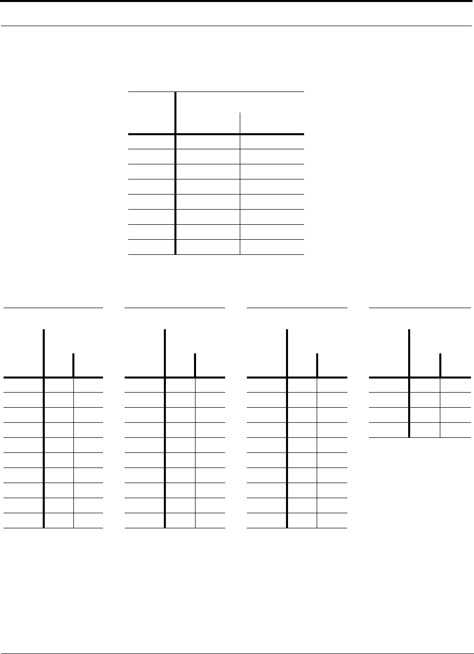
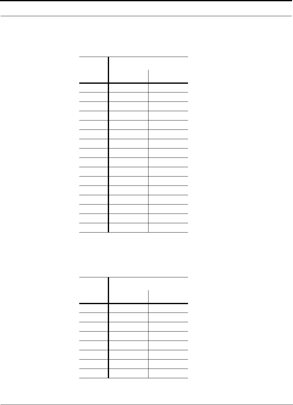
1.3 Acronyms in this Manual
Acronym Definition
AGC automatic gain control
ALC automatic level control
AMPS Advanced Mobile Phone Service
BTS base transceiver station
Cat-5/6 Category 5 or Category 6 (twisted pair cable)
CDMA code division multiple access
CDPD cellular digital packet data
DAS distributed antenna system
dB decibel
dBm decibels relative to 1 milliwatt
DC direct current
DCS Digital Communications System
DL downlink
EDGE Enhanced Data Rates for Global Evolution
EGSM Extended Global Standard for Mobile Communications
GHz gigahertz
GPRS General Packet Radio Service
GSM Groupe Speciale Mobile (now translated in English as Global Standard
for Mobile Communications)
Hz hertz
IF intermediate frequency
iDEN Integrated Digital Enhanced Network (Motorola variant of TDMA
wireless)
LAN local area network
LO local oscillator
mA milliamps
MBS microcellular base station
MH Main Hub
MHz megahertz
MTBF mean time between failures
NF noise figure
nm nanometer
OA&M operation, administration, and maintenance
PCS Personal Communication Services

1-6 InterReach Unison Accel Installation, Operation, and Reference Manual PN 9000-10
620021-0 Rev. A
PLL phase-locked loop
PLS path loss slope
RAU Remote Access Unit
RF radio frequency
RSSI received signal strength indicator
SMA sub-miniature A connector (coaxial cable connector type)
ScTP screened twisted pair
TDMA time division multiple access
UL uplink; Underwriters Laboratories
uW microwatts
UMTS Universal Mobile Telecommunications System
UPS uninterruptable power supply
Wwatt
WCDMA wideband code division multiple access
Acronym Definition

PN 9000-10 Help Hot Line (U.S. only): 1-800-530-9960 1-7
620021-0 Rev. A
1.4 Standards Conformance
• Utilizes the TIA/EIA 568-A Ethernet cabling standards for ease of installation.
• See Appendix C for compliance information.
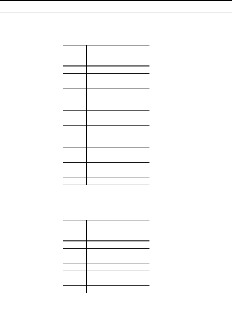
1.5 Related Publications
• AdminManager User Manual, LGC Wireless part number 8810-10

1-8 InterReach Unison Accel Installation, Operation, and Reference Manual PN 9000-10
620021-0 Rev. A

PN 9000-10 InterReach Unison Accel Installation, Operation, and Reference Manual 2-1
620021-0 Rev. A
SECTION 2 InterReach Unison Accel
System Description
InterReach Unison Accel is a wireless networking system that is designed to handle
both wireless voice and data communications over licensed frequencies. It provide
high-quality, ubiquitous, seamless access to the wireless network in smaller build-
ings, including:
• Office buildings
• Hospitals
Accel provides the same RF characteristics as InterReach Unison, which is designed
for large public and private facilities such as campus environments, airports, shop-
ping malls, subways, convention centers, sports venues, etc. Accel uses microproces-
sors to enable key capabilities such as software-selectable band settings, automatic
gain control, ability to incrementally adjust downlink/uplink gain, end-to-end alarm-
ing of all components and the associated cable infrastructure, and a host of additional
capabilities.
The Accel system supports major wireless standards and air interface protocols in use
around the world, including:
• Frequencies: 800 MHz, 900 MHz, 1800 MHz, 1900 MHz, 2100 MHz
• Voice Protocols: AMPS, TDMA, CDMA, GSM/EGSM, iDEN,
• Data Protocols: CDPD, EDGE, GPRS, WCDMA, CDMA2000, 1xRTT,
and Paging

2-2 InterReach Unison Accel Installation, Operation, and Reference Manual PN 9000-10
620021-0 Rev. A
Key System Features
•Superior RF performance, particularly in the areas of IP3 and noise figure.
•High downlink composite power and low uplink noise figure enables support of
a large number of channels and larger coverage footprint per antenna.
•Software configurable Hub. Thus, the frequency band can be configured in the
field.
•Standard Cat-5 or Cat-6 (Cat-5/6) screened twisted pair (ScTP) cabling. The
Cat-5/6 ScTP cable run can be up to 100 meters recommended maximum (150
meters with RF performance degradation).
•Flexible RF configuration capabilities, including:
• System gain:
– Ability to manually set gain in 1 dB steps, from 0 to 15 dB, on both down-
link and uplink.
• RAU:
– RAU uplink and downlink gain can be independently attenuated 10 dB.
– Uplink level control protects the system from input overload and can be
optimized for either a single operator or multiple operators/protocols.
– VSWR check on RAU reports if there is a disconnected antenna (all RAUs
except UMTS).
•Firmware Updates are downloaded (either locally or remotely) to operating sys-
tems when any modifications are made to the product, including the addition of
new software capabilities/services.
•Extensive OA&M capabilities, including fault isolation to the field replaceable
unit, automatic reporting of all fault and warning conditions, and user-friendly
graphical-user interface OA&M software package.
PN 9000-10 Help Hot Line (U.S. only): 1-800-530-9960 2-3
620021-0 Rev. A
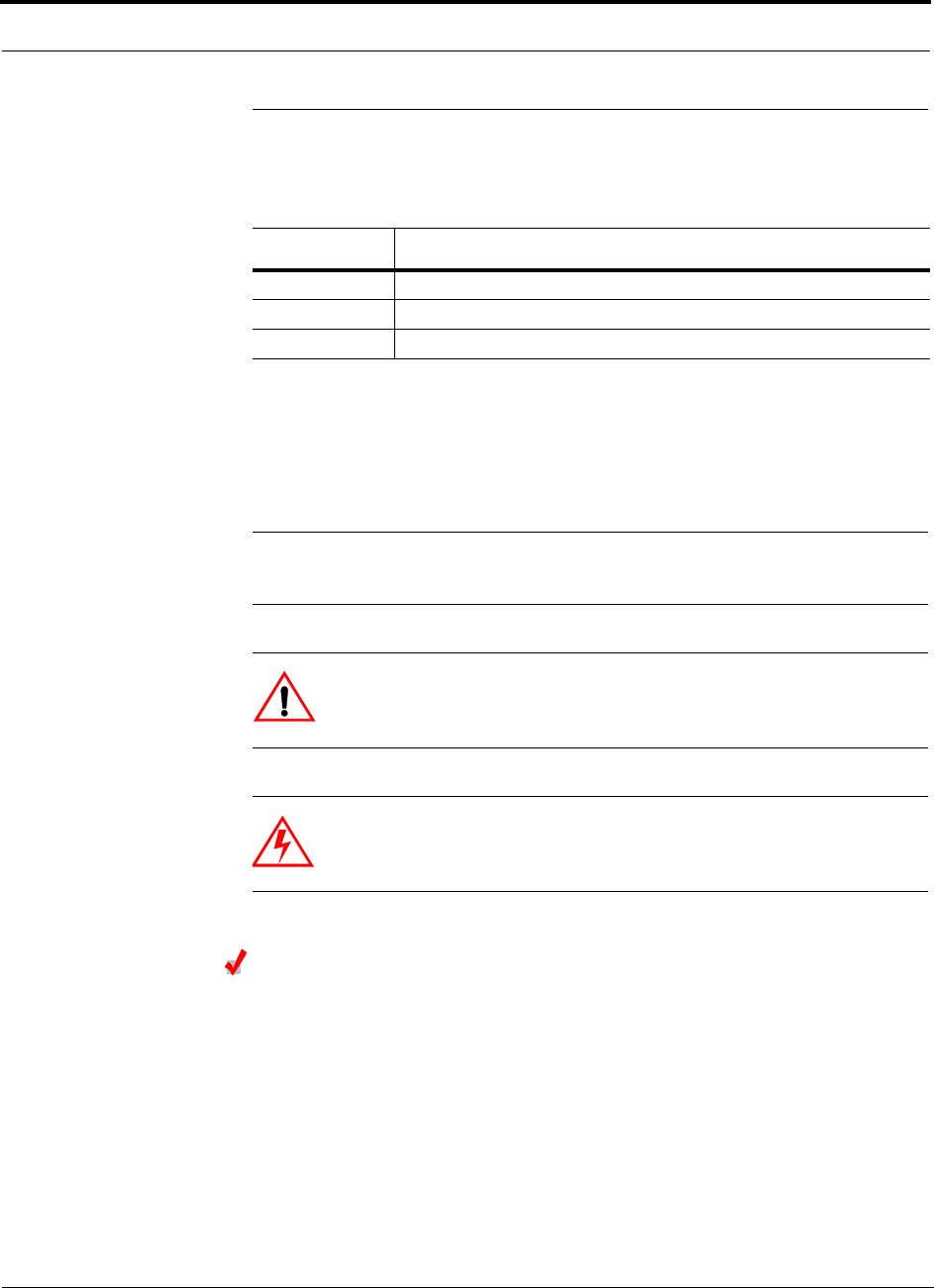
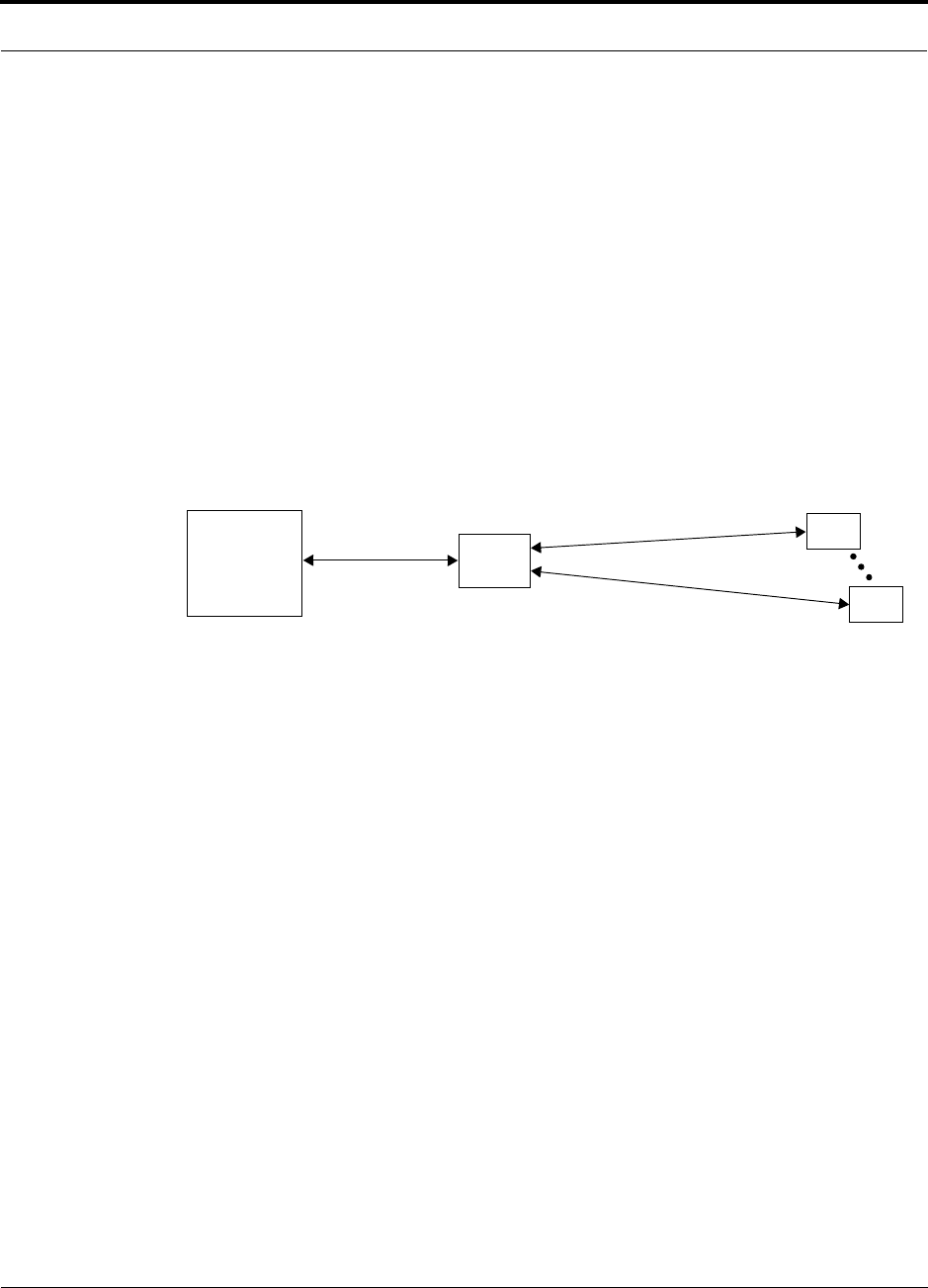
2.1 System Hardware Description
The InterReach Unison Accel system consists of two modular components:
• 19" rack-mountable Hub (connects to up to 8 Remote Access Units)
• Converts RF signals to electrical on the downlink; electrical to RF on the
uplink
• Microprocessor controlled (for alarms, monitoring, and control)
• Software configurable band
• Simplex interface to RF source
• Periodically polls all downstream RAUs for system status, and automatically
reports any fault or warning conditions
• Supplies DC power to RAU
•Remote Access Unit (RAU)
• Converts electrical signals to RF on the downlink; RF to electrical on the
uplink
• Microprocessor controlled (for alarms, monitoring, and control)
• Protocol/band specific units
The minimum configuration of a Unison Accel system is one Hub and one RAU
(1-1). The maximum configuration of a system is one Hub and 8 RAUs (1-8). Multi-
ple systems can be combined to provide larger configurations.
Figure 2-1 Unison Accel System Hardware
2-4 InterReach Unison Accel Installation, Operation, and Reference Manual PN 9000-10
620021-0 Rev. A
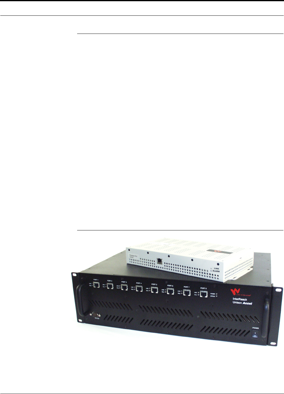
2.2 System OA&M Capabilities Overview
InterReach Unison Accel is microprocessor controlled and contains firmware which
enables much of the operations, administration, and maintenance (OA&M) functionality.
Complete alarming, down to the field replaceable unit (i.e., Hub and Remote Access
Unit) and the cabling infrastructure, is available. All events occurring in a system,
defined as an Accel Hub and all of its associated Remote Access Units, are automati-
cally reported to the Hub. The Hub monitors system status and communicates that
status using the following methods:
• Normally closed (NC) alarm contact closures can be tied to standard NC alarm
monitoring systems or directly to a base station for alarm monitoring.
• The Hub’s front panel serial port connects directly to a PC (for local access) or to a
modem (for remote access).
Figure 2-2 Three Methods for OA&M Communications
AdminManager OA&M software runs on a PC/laptop and communicates with one
Accel Hub, and its downstream RAUs, at a time.
• Connected directly to the Hub’s front panel RS-232 connector, you can access
the Installation Wizard which lets you configure a newly installed system, or
you can access the Configuration & Maintenance panel which lets you query
system status, configure a newly added or swapped unit, or change system
parameters.
• Connected remotely using a modem, AdminManager initiates communications
with the Hub. You can access a read-only Configuration & Maintenance panel
which lets you query system status to help you determine if an on-site visit is
required.
Refer to the AdminManager User Manual (PN 8810-10) for information about
installing and using the AdminManager software.
PSTN
RS-232
RS-232 Ethernet
PC/Laptop
running
Modem
Accel Hub
Modem
Accel Hub
RS-232
ENET/232
Converter
RS-232
RJ-45
Accel Hub
Accel Hub
AdminManager
Use AdminManager to configure
or monitor a local Accel system.
Remotely, AdminManager can only
check system status, it cannot
receive modem calls.
TCP/IP
RAU
1
2
3
PN 9000-10 Help Hot Line (U.S. only): 1-800-530-9960 2-5
620021-0 Rev. A
2.2.1 System Monitoring and Reporting
Each Accel Hub in the system constantly monitors itself and its downstream RAUs
for internal fault and warning conditions. The results of this monitoring are stored in
memory and compared against new results.
When a Hub detects a change in status, a fault or warning is reported. Faults are indi-
cated locally by red status LEDs, and both faults and warnings are reported to the
Hub and displayed on a PC/laptop, via the Hub’s serial port, that is running the
AdminManager software. Passive antennas that are connected to the RAUs are not
monitored automatically. Perform the System Test in order to retrieve status informa-
tion about antennas.
Using AdminManager, you can install a new system or new components, change sys-
tem parameters, and query system status. The following figure illustrates how the sys-
tem reports its status to AdminManager.
Table 2-1 System Monitoring and Reporting
2.2.2 Using Alarm Contact Closures
The DB-9 female connector on the rear panel of the Accel Hub can be connected to a
local base station or to a daisy-chained series of Unison, LGCell, and/or MetroReach
Focus systems.
• When you connect MetroReach Focus or a BTS to Accel, the Accel Hub is the out-
put of the alarms (alarm source) and MetroReach Focus or the BTS is the input
(alarm sense). This is described in Section 6.6.1 on page 6-30.
• When you connect LGCell to Accel, the Accel Hub is the input of the alarms
(alarm sense) and LGCell is the output (alarm source). This is described in
Section 6.6.2 on page 6-33.
Accel
Hub
Each RAU passes its status to
the Hub.
• If a fault is detected, the
ALARM LED is red. If no fault
is detected, the LED is green.
• If a fault or warning condition
is detected, the information is
passed to the Hub.
The Hub queries status of
each RAU and compares it to
previously stored status.
• If a fault is detected, LEDs
on the front panel turn red.
• If a fault or warning condi-
tion is detected in any unit,
the Hub initiates a call to
AdminManager.
PC/Laptop
running
AdminManager
RAU
RAU
Use AdminManager to communi-
cate with one or more remotely or
locally installed systems.
If a fault or warning condition is
reported, the AdminManager graphi-
cal user interface indicates the prob-
lem. AdminManager can also send
an e-mail and/or page notification to
designated recipients.
2-6 InterReach Unison Accel Installation, Operation, and Reference Manual PN 9000-10
620021-0 Rev. A
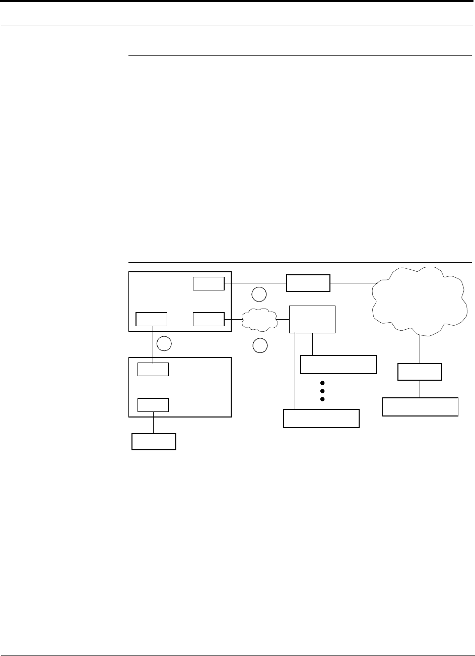
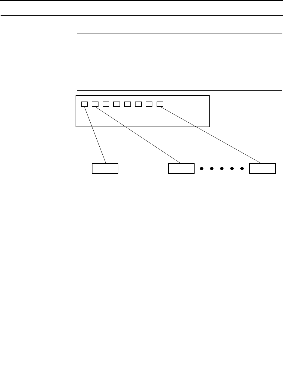
2.3 System Connectivity
The system uses standard Cat-5/6 ScTP. This makes any system expansion, such as
adding an extra antenna for additional coverage, as easy as pulling a twisted pair
cable.
Figure 2-3 Unison Accel’s Architecture
InterReach
Cat-5/6Cat-5/6 Cat-5/6
up to 8 RAUs per Hub
RAU RAU RAU
Unison Accel
PN 9000-10 Help Hot Line (U.S. only): 1-800-530-9960 2-7
620021-0 Rev. A
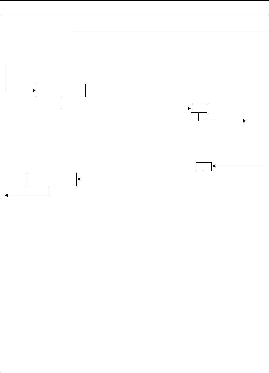
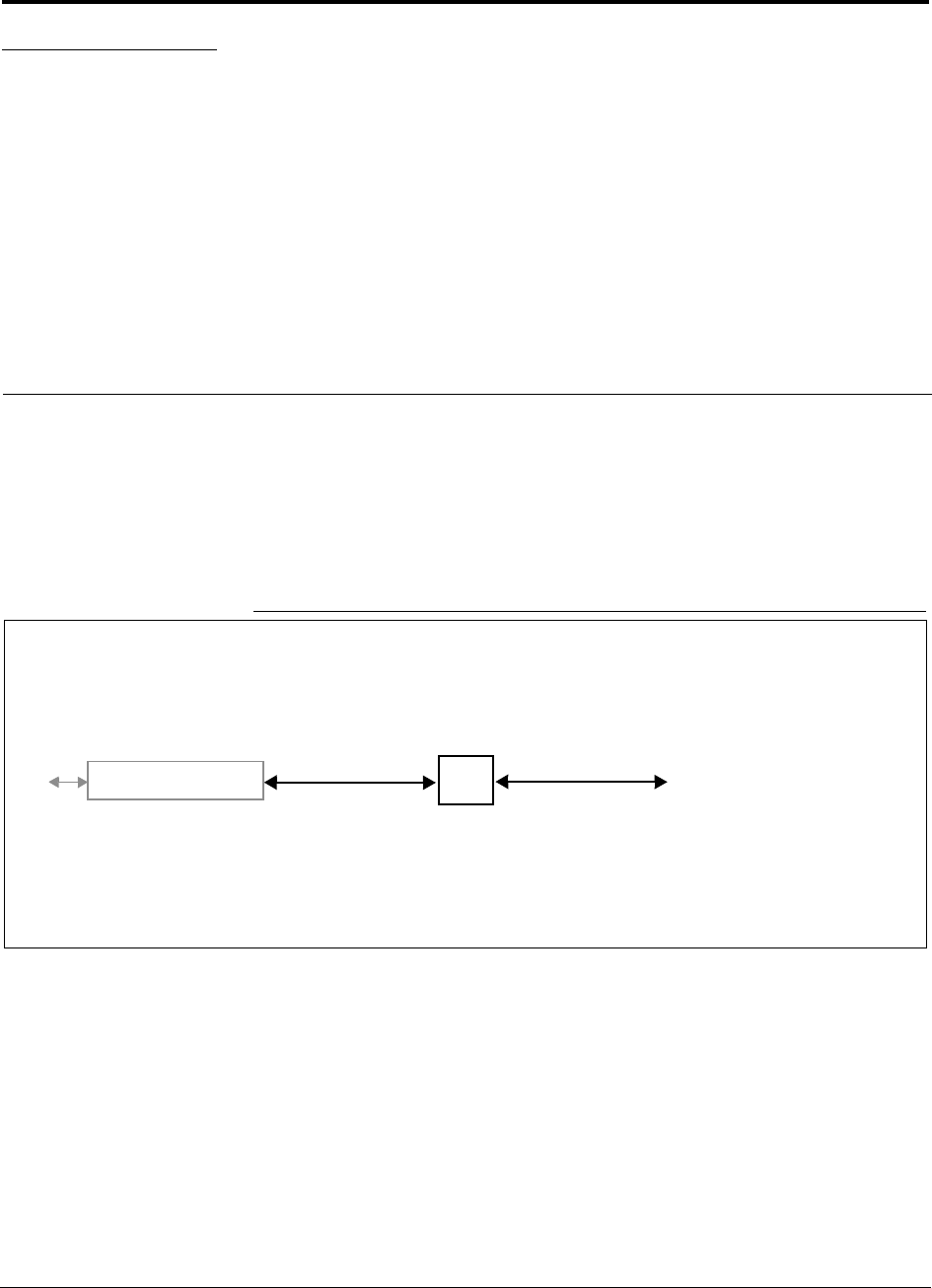
2.4 System Operation
• Downlink (Base Station to Wireless Devices)
• Uplink (Wireless Devices to Base Station)
Accel Hub
RAU
The Accel Hub receives downlink RF signals
from a base station via coaxial cable.
The Hub converts the RF signals to IF
signals and sends them to RAUs (up to 8)
via Cat-5/6 ScTP cable.
The RAU converts the IF signals
to RF and sends them to passive
antennas via coaxial cable.
Accel Hub
RAU
The Accel Hub sends uplink
RF signals to a base station
via coaxial cable.
The Hub receives the IF signals from the
RAUs (up to 8) via Cat-5/6 ScTP cable and
converts to RF signals.
The RAU receives uplink RF
signals from the passive
antenna via coaxial cable and
converts them to IF signals.

2-8 InterReach Unison Accel Installation, Operation, and Reference Manual PN 9000-10
620021-0 Rev. A
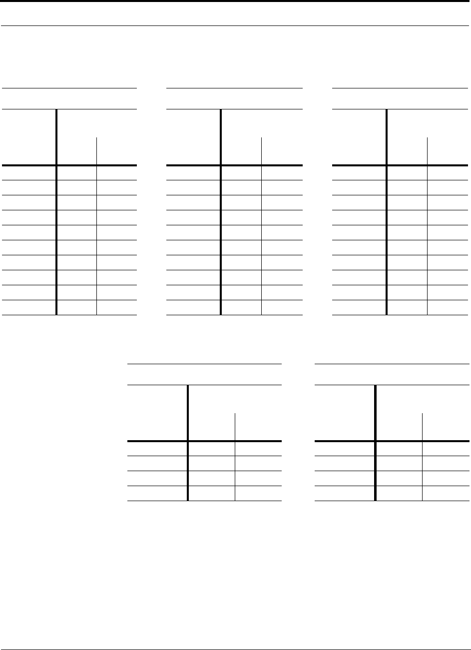
2.5 System Specifications
2.5.1 Physical Specifications
2.5.2 Environmental Specifications
Parameter Unison Accel Hub Remote Access Unit
RF Connectors 8 shielded RJ-45, female (Cat-5/6) 1 shielded RJ-45, female (Cat-5/6)
1 SMA, male (coaxial)
External Alarm Connector
(contact closure)
1 9-pin D-sub, female —
Serial Interface Connector 1 RS-232 9-pin D-sub, male —
LED Alarm and
Status Indicators
Unit Status (1 pair):
•Power
• Status
RAU/Link Status
(1 pair per RJ-45 port):
•Link
•RAU
Unit Status (1 pair):
•Link
•Alarm
AC Power (Volts) Rating: 115/230V, 5.5/3A, 50–60 Hz
Operating Range: 90–132V/170–250V auto-ranging,
4.6–2.3A/3.6–1.6A, 47–63 Hz
—
DC Power (Volts) — 36V (from the Hub)
Power Consumption (W) 4 RAUs: 150 typ/178 max
4 RAUs & 4 Extenders: 167 typ/202 max
8 RAUs: 200 typ/242 max
8 RAUs & 8 Extenders: 234 typ/290 max
16 max (from the Hub)
Enclosure Dimensions*
(height × width × depth)
*Excluding angle-brackets for 19'' rack mounting of hub.
Note: Unison Accel Hub typical power consumption assumes that the Cat-5/6 cable length is no more than 100 meters without a Cat-5 Extender
and no more than 170 meters with a Cat-5 Extender.
133.5 mm × 438 mm × 305 mm
(5.25 in. × 17.25 in. × 12 in.)
44 mm × 305 mm × 158 mm
(1.7 in. × 12 in. × 6.2 in.)
Weight < 8 kg (< 17.5 lb) < 1 kg (< 2 lb)
Parameter Unison Accel Hub RAU
Operating Temperature 0° to +45°C (+32° to +113°F) –25° to +45°C (–13° to +113°F)
Non-operating Temperature –20° to +85°C (–4° to +185°F) –25° to +85°C (–13° to +185°F)
Operating Humidity; non-condensing 5% to 95% 5% to 95%

PN 9000-10 Help Hot Line (U.S. only): 1-800-530-9960 2-9
620021-0 Rev. A
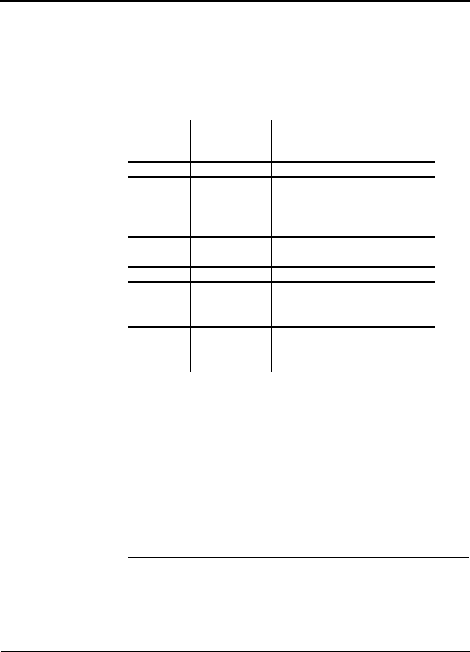
2.5.3 Operating Frequencies
Freq.
Band Unison
Band Description
RF Passband (MHz)
Downlink Uplink
PCS PCS6 Bands A,D,B
(35 MHz)
1930–1965 1850–1885
PCS PCS7 Bands D,B,E,F
(30 MHz)
1945–1975 1865–1895
PCS PCS8 Bands E,F,C
(25 MHz)
1965–1990 1885–1910
DCS DCS1 DCS1 Band 1805–1842.5 1710–1747.5
DCS DCS2 DCS2 Band 1842.5–1880 1747.5–1785
DCS DCS4 DCS4 Band 1815–1850 1720–1755
Cellular CELL – 869–894 824–849
iDEN iDEN – 851–869 806–824
GSM/EGSM GSM/EGSM – 925–960 880–915
UMTS UMTS1 – 2110–2145 1920–1955
UMTS UMTS2 – 2125–2160 1935–1970
UMTS UMTS3 – 2135–2170 1945–1980

2-10 InterReach Unison Accel Installation, Operation, and Reference Manual PN 9000-10
620021-0 Rev. A
2.5.4 RF End-to-End Performance
The following tables list the RF end-to-end performance of each protocol.
NOTE: The system gain is adjustable in 1 dB steps from 0 to 15 dB, and the
gain of each RAU can be attenuated 10 dB in one step.
Cellular 800 MHz
iDEN 800 MHz
GSM/EGSM 900 MHz
Table 2-2 Cellular RF End-to-End Performance
Parameter
Typical
Downlink Uplink
Average gain with 75 m Cat-5 at 25°C (77°F) (dB) 15 15
Ripple with 75 m Cat-5 (dB) 3 3.5
Output IP3 (dBm) 40
Input IP3 (dBm) –7
Output 1 dB Compression Point (dBm) 27
Noise Figure 1 Hub-8 RAUs (dB) 15
Table 2-3 iDEN RF End-to-End Performance
Typical
Parameter Downlink Uplink
Average gain with 75 m Cat-5/6 at 25°C (77°F) (dB) 15 15
Ripple with 75 m Cat-5/6 (dB) 2 3
Output IP3 (dBm) 38
Input IP3 (dBm) –7
Output 1 dB Compression Point (dBm) 26
Noise Figure 1 Hub-8 RAUs (dB) 17
Table 2-4 GSM/EGSM RF End-to-End Performance
Typical
Parameter Downlink Uplink
Average Downlink gain with 75 m Cat-5/6 at 25°C (77°F) (dB) 15 15
Ripple with 75 m Cat-5/6 (dB) 3 4
Output IP3 (dBm) 38
Input IP3 (dBm) –7
Output 1 dB Compression Point (dBm) 26
Noise Figure 1 Hub-8 RAUs (dB) 16

PN 9000-10 Help Hot Line (U.S. only): 1-800-530-9960 2-11
620021-0 Rev. A
DCS 1800 MHz
PCS 1900 MHz
UMTS 2.1 GHz
Table 2-5 DCS RF End-to-End Performance
Typical
Parameter Downlink Uplink
Average gain with 75 m Cat-5/6 at 25°C (77°F) (dB) 15 15
Downlink ripple with 75 m Cat-5/6 (dB) 2
Uplink ripple for center 35 MHz of DCS1 and DCS2, Full band for DCS4
with 75 m Cat-5/6 (dB) 2
Uplink gain roll off for Full band of DCS1 and DCS2 with 75 m Cat-5/6 (dB) 2
Output IP3 (dBm) 38
Input IP3 (dBm) –12
Output 1 dB Compression Point (dBm) 26
Noise Figure 1 Hub-8 RAUs (dB) 17
Table 2-6 PCS RF End-to-End Performance
Parameter
Typical
Downlink Uplink
Average gain with 75 m Cat-5 at 25°C (77°F) (dB) 15 15
Ripple with 75 m Cat-5 (dB) 2.5 3
Output IP3 (dBm) 38
Input IP3 (dBm) –12
Output 1 dB Compression Point (dBm) 26
Noise Figure 1 Hub-8 RAUs (dB) 16
Table 2-7 UMTS RF End-to-End Performance
Parameter
Typical
Downlink Uplink
Average Gain w/75 meters Cat-5/6 @ 25
°
C (dB) 15 15
Ripple w/75 meters Cat-5/6 (dB) 2.5 4
Noise Figure: 1 Accel Hub and 8 RAUs (dB) 16
Spurious Output Levels (dBm) <–30
UMTS TDD Band Spurious Output Level
1900–1920 MHz, 2010–2025 MHz (dBm/MHz) <–52
Waveform Quality (at maximum power) (
ρ
) > 0.97 > 0.97
Output IP3 (dBm) 37
Input IP3 (dBm) –12
Output P1dB (dBm) 26

2-12 InterReach Unison Accel Installation, Operation, and Reference Manual PN 9000-10
620021-0 Rev. A
PN 9000-10 InterReach Unison Accel Installation, Operation, and Reference Manual 3-1
620021-0 Rev. A
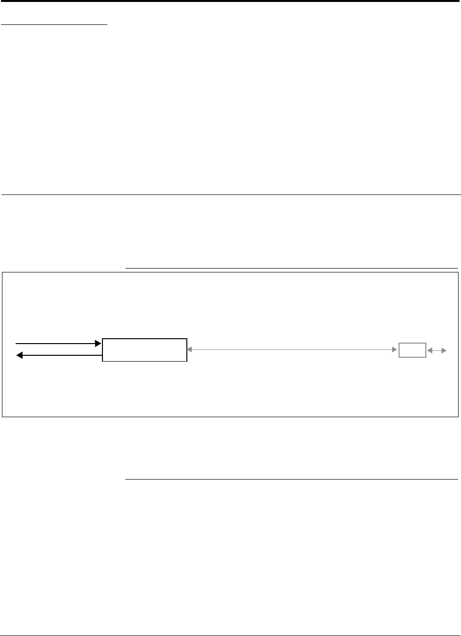
SECTION 3 Accel Hub
The Accel Hub distributes downlink RF signals from a base station, repeater, or
MetroReach Focus system to up to eight Remote Access Units. The Hub also com-
bines uplink signals from the RAUs.
Figure 3-1 Accel Hub in a Unison System
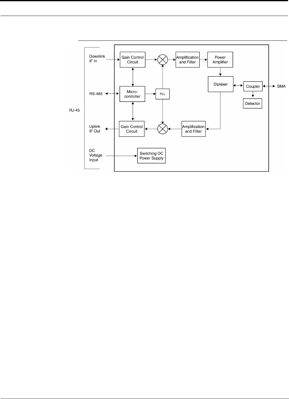
Figure 3-2 gives a detailed view of the major RF and functional blocks of the Accel
Hub.
Figure 3-2 Accel Hub Block Diagram
Accel Hub RAU
Downlink Path: The Accel Hub receives downlink RF signals from a base station, repeater, or MetroReach Focus system via
coaxial cable. It converts the signals to IF and sends them to up to eight RAUs via Cat-5/6 cable.
The Hub also sends OA&M communication to the RAUs via the Cat-5/6 cable.
Uplink Path: The Accel Hub receives uplink IF signals from up to eight RAUs via Cat-5/6 cable. It converts the signals to RF
and sends them to a base station, repeater, or MetroReach Focus system via coaxial cable.
The Hub also receives status information from the RAUs via the Cat-5/6 cable.
Downlink to Main Hub
Uplink from Main Hub
Dave: Please provide
(see RAU for example)
3-2 InterReach Unison Accel Installation, Operation, and Reference Manual PN 9000-10
620021-0 Rev. A
3.1 Accel Hub Front Panel
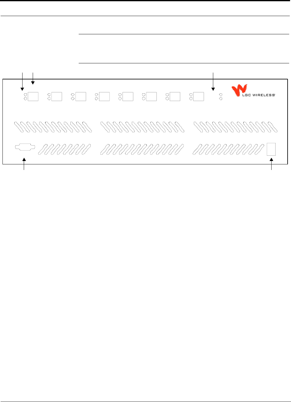
Figure 3-3 Accel Hub Front Panel
1. Eight standard Cat-5/6 ScTP cable RJ-45 connectors (labeled PORT 1, 2, 3, 4, 5, 6,
7, 8)
2. Eight sets of RJ-45 port LEDs (one set per port)
• One LED per port for link status (labeled LINK)
• One LED per port for downstream unit status (labeled RAU)
3. One set of unit status LEDs
• One LED for unit power status (labeled POWER)
• One LED for unit status (labeled MAIN HUB STATUS)
4. One 9-pin D-sub male connector for system communication and diagnostics using
a PC/laptop or modem (labeled RS-232)
5. Power switch.
LINK
RAU
PORT 1
LINK
RAU
PORT 2
LINK
RAU
PORT 3
LINK
RAU
PORT 4
LINK
RAU
PORT 5
LINK
RAU
PORT 6
LINK
RAU
PORT 7
LINK
RAU
PORT 8
POWER
STATUS
POWER
InterReach
Unison Accel
RS-232
1
2
4
2 3
5

PN 9000-10 Help Hot Line (U.S. only): 1-800-530-9960 3-3
620021-0 Rev. A
3.1.1 RJ-45 Connectors
The eight RJ-45 connectors on the Hub are for the Cat-5/6 ScTP cables that are used
to transmit and receive signals to and from RAUs. Use shielded RJ-45 connectors on
the Cat-5/6 cable.
NOTE: For system performance, it is important that you use only Cat-5/6 ScTP
(screened twisted pair) cable with shielded RJ-45 connectors.
The Cat-5/6 cable also delivers DC electrical power to the RAUs. The Hub’s DC
voltage output is 36V DC nominal. A current limiting circuit is used to protect the
Hub if any port draws excessive power.
3.1.2 Communications RS-232 Serial Connector
Remote Monitoring
Use a standard serial cable to connect a modem to the 9-pin D-sub male serial con-
nector for remote monitoring or configuring. The cable typically has a DB-9 female
and a DB-25 male connector. See Appendix A.3 on page A-3 for the cable pinout.
Local Monitoring
Use a null modem cable to connect a laptop or PC to the 9-pin D-sub male serial con-
nector for local monitoring or configuring. The cable typically has a DB-9 female
connector on both ends. See Appendix A.4 on page A-4 for the cable pinout.
3-4 InterReach Unison Accel Installation, Operation, and Reference Manual PN 9000-10
620021-0 Rev. A
3.1.3 Hub LED Indicators
The unit’s front panel LEDs indicate faults and commanded or fault lockouts. The
LEDs do not indicate warnings or whether the system test has been performed. Only
use the LEDs to provide basic information or as a backup when you are not using
AdminManager.
Upon power up, the Hub goes through a five-second test to check the LED lamps.
During this time, the LEDs blink through the states shown in Table 3-1, letting you
visually verify that the LED lamps and the firmware are functioning properly.
The Hub will automatically send the program band command to all
connected RAUs. A mismatched band will cause an error message
to be displayed in AdminManager and the RAU will have a fault con-
dition.
NOTE: Refer to Section 8 for troubleshooting using the LEDs.
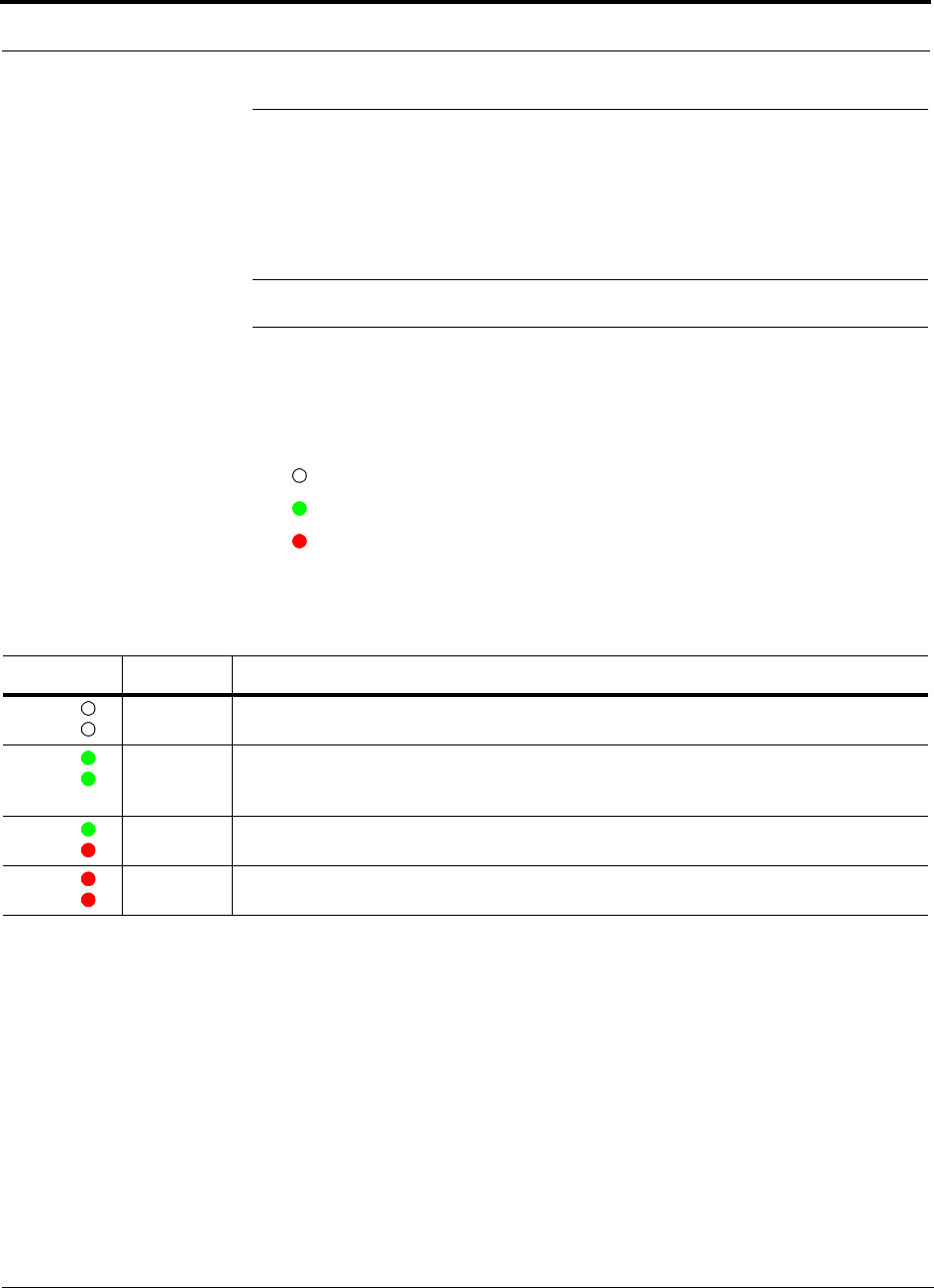
Status LEDs
The Hub status LEDs can be in one of the states shown in Table 3-1. These LEDs can
be:
steady green
steady red
blinking green/red (alternating green/red)
There is no off state when the unit’s power is on.
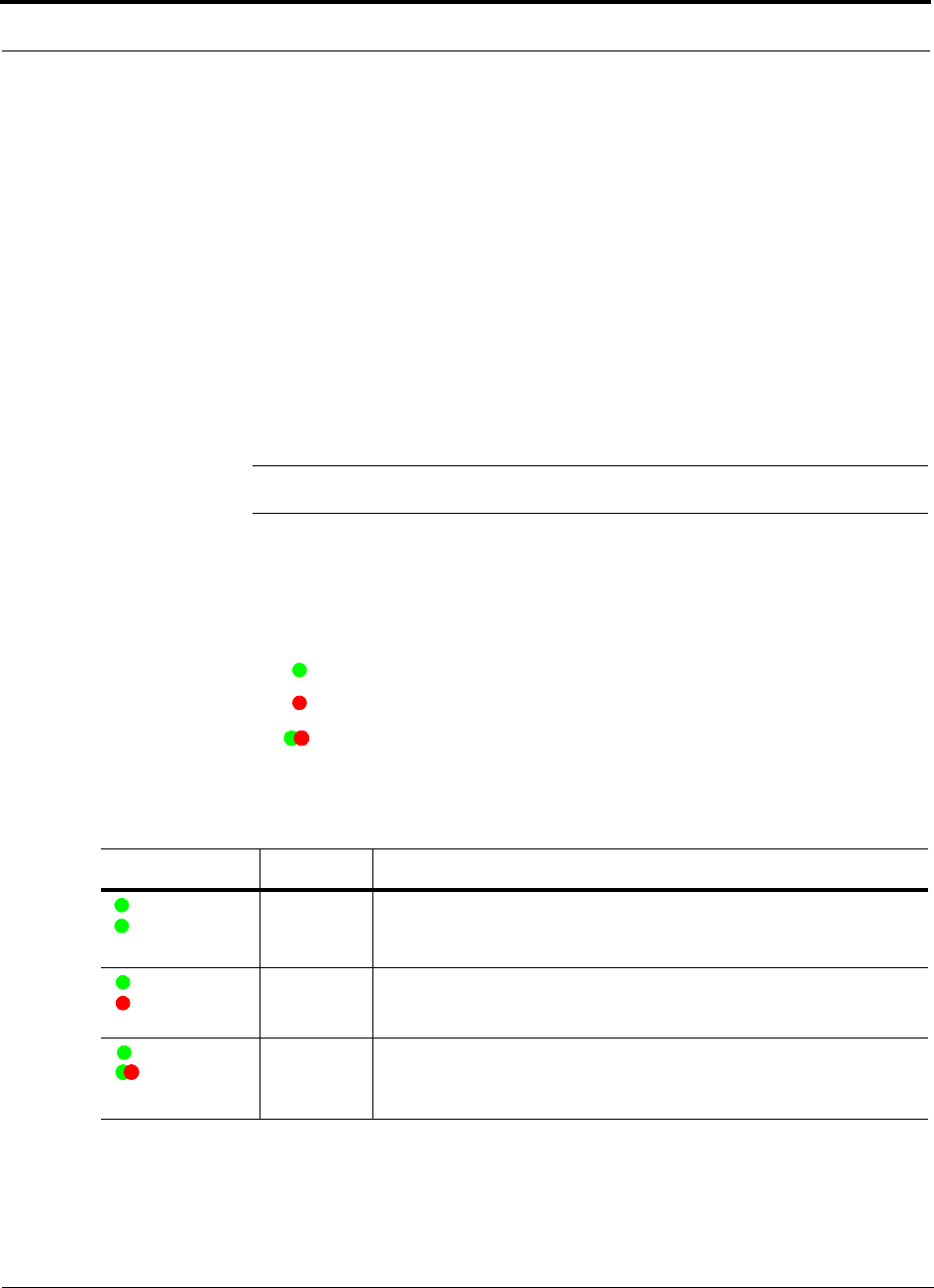
Table 3-1 Accel Hub Status LED States
LED State Indicates
Green
Green
• Hub is connected to power
• Hub is not reporting a fault; but the system test may need to be per-
formed or a warning could exist (use AdminManager to determine)
Green
Red
• Hub is connected to power
• Hub is reporting a fault or lockout condition
Green
Alternating
Green/Red
• Hub is connected to power
• Hub input signal level too high
POWER
STATUS
POWER
STATUS
POWER
STATUS
PN 9000-10 Help Hot Line (U.S. only): 1-800-530-9960 3-5
620021-0 Rev. A
Port LEDs
The Hub has one pair of port LEDs for each of the eight RJ-45 ports. The port LEDs
can be in one of the states shown in Table 3-2. These LEDs can be:
off
steady green
steady red
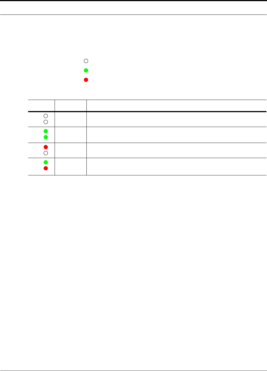
Table 3-2 Accel Hub Port LED States
LED State Indicates
Off
Off
• RAU is not connected
Green
Green
• RAU is connected
• No faults from RAU
Red
Off
• Loss of communications to RAU
Green
Red
• RAU is connected
• RAU is reporting a fault or lockout condition
LINK
RAU
LINK
RAU
LINK
RAU
LINK
RAU
3-6 InterReach Unison Accel Installation, Operation, and Reference Manual PN 9000-10
620021-0 Rev. A
3.2 Accel Hub Rear Panel
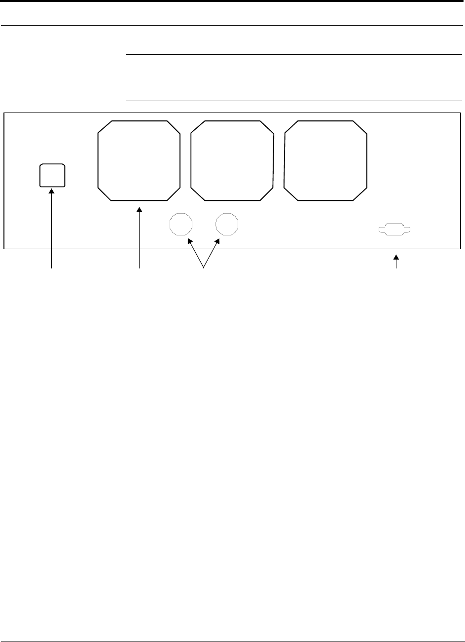
Figure 3-4 Accel Hub Rear Panel
1. AC power cord connector
2. Three air exhaust vents
3. Two N-type, female connectors:
• Downlink (labeled DOWNLINK)
• Uplink (labeled UPLINK)
4. One 9-pin D-sub female connector for contact closure monitoring (labeled
DIAGNOSTIC 1)
Are the back panel items labeled?
1 2 3 4

PN 9000-10 Help Hot Line (U.S. only): 1-800-530-9960 3-7
620021-0 Rev. A
3.2.1 Accel Hub Rear Panel Connectors
3.2.1.1 9-pin D-sub Connector
The 9-pin D-sub connector (labeled DIAGNOSTIC 1) provides contact closure for
major and minor error system alarm monitoring.
The following table lists the function of each pin on the 9-pin D-sub connector.
This interface can either generate contact alarms or sense a single external alarm con-
tact.
3.2.1.2 N-type Female Connectors
There are two N-type female connectors on the rear panel of the Hub:
•The
DOWNLINK connector receives downlink RF signals from a repeater, local
base station, or MetroReach Focus system.
•The
UPLINK connector transmits uplink RF signals to a repeater, local base sta-
tion, or MetroReach Focus system.
Pin Function
1 Alarm Input Ground
2 Reserved
3 Reserved
4 Warning Contact (positive connection)
5 Warning Contact (negative connection)
6 DC Ground (common)
7 Fault Contact (positive connection)
8 Alarm Input
9 Fault Contact (negative connection)

3-8 InterReach Unison Accel Installation, Operation, and Reference Manual PN 9000-10
620021-0 Rev. A
3.3 Faults and Warnings
The Accel Hub monitors and reports changes in system performance to:
• Ensure that its amplifiers and IF/RF path are functioning properly.
• Ensure that Remote Access Units are connected and functioning properly.
The Accel Hub periodically queries attached Remote Access Units for their status.
Both faults and warnings are reported to a connected PC/laptop that is running the
AdminManager software. Only faults are indicated by LEDs.
For more information, see:
• page 8-3 for Hub faults.
• page 8-7 for Hub warnings.
• page 8-8 for Hub status messages.
• page 8-11 for troubleshooting Hub LEDs.

PN 9000-10 Help Hot Line (U.S. only): 1-800-530-9960 3-9
620021-0 Rev. A
3.4 Accel Hub Specifications
Table 3-3 Accel Hub Specifications
Specification Description
Enclosure Dimensions (H × W × D): 133.5 mm × 438 mm × 305 mm (5.25 in. × 17.25 in. × 12 in.)
Weight < 8 kg (< 17.5 lb)
Operating Temperature 0° to +45°C (+32° to +113°F)
Non-operating Temperature –20° to +85°C (–4° to +185°F)
Operating Humidity, non-condensing 5% to 95%
External Alarm Connector
(contact closure)
1 9-pin D-sub, female
Maximum: 40 mA @ 40V DC
Typical: 4 mA @ 12V DC
Serial Interface Connector 1 RS-232 9-pin D-sub, male
RF Connectors 8 shielded RJ-45, female (Cat-5/6)
LED Fault and Status Indicators Unit Status (1 pair):
•Power
• Main Hub Status
Downstream Unit/Link Status (1 pair per Cat-5/6 port):
•Link
•RAU
AC Power Rating: 115/230V, 5.5/3A, 50–60 Hz
Operating Range: 90–132V/170–250V auto-ranging,
4.6–2.3A/3.6–1.6A, 47–63 Hz
Power Consumption (W) 4 RAUs: 150 typ/178 max
4 RAUs & 4 Extenders: 167 typ/202 max
8 RAUs: 200 typ/242 max
8 RAUs & 8 Extenders: 234 typ/290 max
MTBF 78,998 hours

3-10 InterReach Unison Accel Installation, Operation, and Reference Manual PN 9000-10
620021-0 Rev. A
PN 9000-10 InterReach Unison Accel Installation, Operation, and Reference Manual 4-1
620021-0 Rev. A
SECTION 4 Unison Remote Access Unit
The Remote Access Unit (RAU) is an active transceiver that connects to an Accel
Hub using industry-standard Cat-5/6 screened twisted pair (ScTP) cable, which deliv-
ers RF signals, configuration information, and electrical power to the RAU.
An RAU passes RF signals between an Accel Hub and an attached passive antenna
where the signals are transmitted to wireless devices.
Figure 4-1 Remote Access Unit in a Unison Accel System
RAU
Downlink Path: The RAU receives downlink IF signals from an Accel Hub via Cat-5/6 cable. It converts the signals to RF
and sends them to a passive RF antenna via coaxial cable.
Also, the RAU receives configuration information from the Accel Hub via the Cat-5/6 cable.
Uplink Path: The RAU receives uplink RF signals from a passive RF antenna via coaxial cable. It converts the signals to IF
and sends them to an Accel Hub via Cat-5/6 cable.
Also, the RAU sends its status information to the Accel Hub via the Cat-5/6 cable.
Downlink to RAU
Uplink from RAU
Unison Accel Hub Downlink to antenna
Uplink from antenna
4-2 InterReach Unison Accel Installation, Operation, and Reference Manual PN 9000-10
620021-0 Rev. A
Figure 4-2 Remote Access Unit Block Diagram
PN 9000-10 Help Hot Line (U.S. only): 1-800-530-9960 4-3
620021-0 Rev. A
The Unison RAUs are manufactured to a specific band or set of bands (i.e., there is
one PCS RAU which can be used for A/D, B/E, E/F, B/D, or F/C). Table 4-1 lists the
six Unison RAUs, the Unison Band, and the frequency band(s) they cover.
4.1 Remote Access Unit Connectors
4.1.1 SMA Connector
The RAU has one female SMA connector. The connector is a duplexed RF input/out-
put port that connects to a standard passive antenna using coaxial cable.
4.1.2 RJ-45 Connector
The RAU has one RJ-45 connector that connects it to an Accel Hub using Cat-5/6
ScTP cable. Use shielded RJ-45 connectors on the Cat-5/6 cable.
NOTE: For system performance, it is important that you use only Cat-5/6 ScTP
cable with shielded RJ-45 connectors.
Table 4-1 Frequency Bands covered by Unison RAUs
Unison
RAU Unison
Band
RF Passband
Downlink (MHz) Uplink (MHz)
Cellular Cellular 869–894 824–849
DCS DCS1 1805–1842.5 1710–1747.5
DCS2 1842.5–1880 1747.5–1785
DCS3 1840–1875 1745–1780
DCS4 1815–1850 1720–1755
GSM GSM 925–960 880–915
EGSM 935–960 890–915
iDEN iDEN 851–869 806–824
PCS Bands A,D,B 1930–1965 1850–1885
Bands D,B,E,F 1945–1975 1865–1895
Bands E,F,C 1965–1990 1885–1910
UMTS UMTS 1 2110–2145 1945–1975
UMTS 2 2125–2160 1965–1990
UMTS 3 2135–2170 1945–1980
4-4 InterReach Unison Accel Installation, Operation, and Reference Manual PN 9000-10
620021-0 Rev. A
4.2 RAU LED Indicators
Upon power up, the RAU goes through a two-second test to check the LED lamps.
During this time, the LEDs blink green/green red/red, letting you visually verify that
the LED lamps and the firmware are functioning properly.
NOTE: Refer to Section 8 for troubleshooting using the LEDs.
Status LEDs
The RAU status LEDs can be in one of the states shown in Table 4-2. These LEDs
can be:
off
steady green
steady red
There is no off state when the unit’s power is on.
Table 4-2 Remote Access Unit LED States
LED State Indicates
Off
Off
• RAU is not receiving DC power
Green
Green
• RAU is powered and is not indicating a fault condition. Communication with Accel Hub is
normal; but the system test may need to be performed or a warning condition could exist
(use AdminManager to determine)
Green
Red
• RAU is indicating a fault or lockout condition, but communication with the Accel Hub is
normal
Red
Red
• RAU is reporting a fault or lockout condition, and it is not able to communicate with the
Accel Hub
LINK
ALARM
LINK
ALARM
LINK
ALARM
LINK
ALARM

PN 9000-10 Help Hot Line (U.S. only): 1-800-530-9960 4-5
620021-0 Rev. A
4.3 Faults and Warnings
Both fault and warning conditions are reported to the Accel Hub where they are
stored. Only faults are indicated by LEDs.
For more information, see:
• page 8-6 for RAU faults.
• page 8-7 for RAU warnings.
• page 8-9 for RAU status messages.
4.4 Remote Access Unit Specifications
Table 4-3 Remote Access Unit Specifications
Specification Description
Dimensions (H × W × D) 44 mm × 305 mm × 158 mm (1.7 in. × 12 in. × 6.2 in.)
Weight < 1 kg (< 2 lb)
Operating Temperature –25° to +45°C (–13° to +113°F)
Non-operating Temperature –25° to +85°C (–13° to +185°F)
Operating Humidity, non-condensing 5% to 95%
RF Connectors 1 shielded RJ-45, female (Cat-5/6)a
1 SMA, male (coaxial)
a. For system performance, it is important that you use only Cat-5/6 ScTP cable with shielded RJ-45 connectors.
LED Alarm and Status Indicators Unit Status (1 pair): • Link • Alarm
Maximum Heat Dissipation (W) 16 max (from the Hub)
MTBF 282,207 hours

4-6 InterReach Unison Accel Installation, Operation, and Reference Manual PN 9000-10
620021-0 Rev. A
4.5 RAUs in a Dual Band System
A Dual-Band Diplexer can be used to combine the output from two RAUs, one that is
below 1 GHz and one that is above 1 GHz, for output to a single passive antenna..
Refer to the Dual Band Diplexer specifications (PN 8000-54) for technical informa-
tion.
Unison
RAU
Unison
RAU
Dual Band
Diplexer
Cat-5/6 from Accel Hub
Cat-5/6 from Accel Hub
Antenna
3 ft. coaxial cable
3 ft. coaxial cable

PN 9000-10 InterReach Unison Accel Installation, Operation, and Reference Manual 5-1
620021-0 Rev. A
SECTION 5 Designing a Unison Accel
Solution
Designing a Unison Accel solution is ultimately a matter of determining coverage and
capacity needs. This requires the following steps:
1. Determine the wireless service provider’s requirements.
This information is usually determined by the service provider:
• Frequency (i.e., 850 MHz)
• Band (i.e., “A” band in the Cellular spectrum)
• Protocol (i.e., TDMA, CDMA, GSM, iDEN)
• Peak capacity requirement (this, and whether or not the building will be split
into sectors, determines the number of carriers that the system will have to
transmit)
• Design goal (RSSI, received signal strength at the wireless handset,
i.e., –85 dBm)
The design goal is always a stronger signal than the cell phone needs. It
includes inherent factors which will affect performance (see Section 5.4.1 on
page 5-30).
• RF source (base station or BDA), type of equipment if possible
2. Determine the power per carrier and input power from the base station or
BDA into the Main Hub: Section 5.1, “Maximum Output Power per Carrier
at RAU,” on page 5-3.
The maximum power per carrier is a function of the number of RF carriers, the
carrier headroom requirement, signal quality issues, regulatory emissions require-
ments, and Unison’s RF performance. Typically, the power per carrier decreases
as the number of carriers increases.
3. Determine the in-building environment: Section 5.2, “Estimating RF Cover-
age,” on page 5-17.
• Determine which areas of the building require coverage (entire building, public
areas, parking levels, etc.)

5-2 InterReach Unison Accel Installation, Operation, and Reference Manual PN 9000-10
620021-0 Rev. A
• Obtain floor plans to determine floor space of building and the wall layout of
the proposed areas to be covered. Floor plans will also be useful when you are
selecting antenna locations.
• If possible, determine the building’s construction materials (sheetrock, metal,
concrete, etc.)
• Determine type of environment
– Open layout (e.g., a convention center)
– Dense, close walls (e.g., a hospital)
– Mixed use (e.g., an office building with hard wall offices and cubicles)
4. Develop an RF link budget: Section 5.4, “Link Budget Analysis,” on page
5-29.
Knowing the power per carrier, you can calculate an RF link budget which is used
to predict how much propagation loss can be allowed in the system, while still
providing satisfactory performance throughout the area being covered. The link
budget is a methodical way to derive a “design goal”. If the design goal is pro-
vided in advance, the link budget is simply: allowable RF loss = maximum power
per carrier – design goal.
5. Determine the appropriate estimated path loss slope that corresponds to the
type of building and its layout, and estimate the coverage distance for each
RAU: Section 5.2, “Estimating RF Coverage,” on page 5-17.
The path loss slope (PLS), which gives a value to the RF propagation characteris-
tics within the building, is used to convert the RF link budget into an estimate of
the coverage distance per antenna. This will help establish the Unison equipment
quantities you will need. The actual path loss slope that corresponds to the spe-
cific RF environment inside the building can also be determined empirically by
performing an RF site-survey of the building. This involves transmitting a cali-
brated tone for a fixed antenna and making measurements with a mobile antenna
throughout the area surrounding the transmitter.
6. Determine the items required to connect to the base station: Section 5.5,
“Connecting a Main Hub to a Base Station,” on page 5-42.
Once you know the quantities of Unison equipment you will use, you can deter-
mine the accessories (combiners/dividers, surge suppressors, repeaters, attenua-
tors, circulators, etc.) that are required to connect the system to the base station.
The individual elements that must be considered in designing a Unison solution are
discussed in the following sections.
PN 9000-10 Help Hot Line (U.S. only): 1-800-530-9960 5-3
620021-0 Rev. A
5.1 Maximum Output Power per Carrier at RAU
The following tables show the recommended maximum power per carrier out of the
RAU SMA connector for different frequencies, formats, and numbers of carriers.
These limits are dictated by RF signal quality and regulatory emissions issues. The
maximum input power to the Main Hub is determined by subtracting the system gain
from the maximum output power of the RAU. System gain is software selectable
from 0 dB to 15 dB in 1 dB steps. Additionally, both the uplink and downlink of each
RAU gain can be reduced by 10 dB.
When you connect a Main Hub to a base station or repeater, the RF power per carrier
usually needs to be attenuated in order to avoid exceeding Unison’s maximum output
power recommendations.
Refer to Section 5.6, “Designing for a Neutral Host System,” on page 5-46 when
combining frequencies or protocols on a single Main Hub.
WARNING: Exceeding the maximum input power could cause per-
manent damage to the Main Hub. Do not exceed the maximum com-
posite input power of 1W (+30 dBm) to the Main Hub at any time.
NOTE: These specifications are for downlink power at the RAU output (excluding
antenna).

5-4 InterReach Unison Accel Installation, Operation, and Reference Manual PN 9000-10
620021-0 Rev. A
800 MHz AMPS
Table 5-1 800 MHz (AMPS) Power per Carrier
No. of
Carriers
Power per Carrier (dBm)
2 km SMF 1 km MMF
1 27.0 27.0
2 21.0 21.0
3 17.5 17.5
4 14.5 14.5
5 13.0 13.0
611.5 11.5
7 10.5 10.5
89.5 9.5
99.0 9.0
10 8.0 8.0
11 8.0 8.0
12 7.5 7.5
13 7.0 7.0
14 6.5 6.5
15 6.5 6.5
16 6.0 6.0
20 5.0 5.0
30 3.0 3.0

PN 9000-10 Help Hot Line (U.S. only): 1-800-530-9960 5-5
620021-0 Rev. A
800 MHz TDMA
Table 5-2 800 MHz (TDMA) Power per Carrier
No. of
Carriers
Power per Carrier (dBm)
2 km SMF 1 km MMF
124.0 24.0
219.0 19.0
316.0 16.0
414.0 14.0
512.5 12.5
611.5 11.5
710.5 10.5
89.5 9.5
99.0 9.0
10 8.5 8.5
11 8.0 8.0
12 7.5 7.5
13 7.5 7.5
14 7.0 7.0
15 6.5 6.5
16 6.5 6.5
20 5.5 5.5
30 3.5 3.5
5-6 InterReach Unison Accel Installation, Operation, and Reference Manual PN 9000-10
620021-0 Rev. A
800 MHz CDMA
800 MHz iDEN
Table 5-3 800 MHz (CDMA) Power per Carrier
No. of
Carriers
Power per Carrier (dBm)
2 km SMF 1 km MMF
1 17.0 17.0
2 14.0 14.0
3 12.0 12.0
411.0 11.0
5 10.0 10.0
69.0 9.0
78.5 8.5
88.0 8.0
Table 5-4 800 MHz iDEN/SMR Power per Carrier
iDEN Analog FM CQPSK/C4FM Motient Data TAC
No. of
Carriers
Power per
Carrier (dBm)
No. of
Carriers
Power per
Carrier (dBm)
No. of
Carriers
Power per
Carrier (dBm)
No. of
Carriers
Power per
Carrier (dBm)
2 km
SMF 1 km
MMF 2 km
SMF 1 km
MMF 2 km
SMF 1 km
MMF 2 km
SMF 1 km
MMF
1 10.0 10.0 1 10.0 10.0 1 10.0 10.0 1 10.0 10.0
2 10.0 10.0 2 10.0 10.0 2 10.0 10.0 2 10.0 10.0
3 10.0 10.0 3 10.0 10.0 3 10.0 10.0 3 10.0 10.0
4 10.0 10.0 4 10.0 10.0 4 10.0 10.0 4 10.0 10.0
5 9.0 9.0 5 10.0 10.0 5 10.0 10.0
6 8.0 8.0 6 10.0 10.0 6 10.0 10.0
7 7.0 7.0 7 9.5 9.5 7 9.0 9.0
8 6.5 6.5 8 8.5 8.5 8 8.5 8.5
9 6.0 6.0 9 8.0 8.0 9 7.5 7.5
10 5.5 5.5 10 7.0 7.0 10 7.0 7.0

PN 9000-10 Help Hot Line (U.S. only): 1-800-530-9960 5-7
620021-0 Rev. A
900 MHz GSM or EGSM
Table 5-5 900 MHz (GSM or EGSM) Power per Carrier
No. of
Carriers
Power per Carrier (dBm)
2 km SMF 1 km MMF
116.0 16.0
213.0 12.0
3 11.0 10.0
410.0 9.0
59.0 8.0
68.0 7.0
77.5 6.5
87.0 6.0
96.5 5.5
10 6.0 5.5
11 5.5 5.0
12 5.0 4.5
13 5.0 4.5
14 4.5 4.0
15 4.0 4.0
16 4.0 3.5

5-8 InterReach Unison Accel Installation, Operation, and Reference Manual PN 9000-10
620021-0 Rev. A
900 MHz EDGE
Table 5-6 900 MHz (EDGE) Power per Carrier
No. of
Carriers
Power per Carrier (dBm)
2 km SMF 1 km MMF
1 16.0 16.0
2 13.0 12.0
3 11.0 10.0
410.0 9.0
59.0 8.0
68.0 7.0
77.5 6.5
87.0 6.0
96.5 5.5
10 6.0 5.5
11 5.5 5.0
12 5.0 4.5
13 5.0 4.5
14 4.5 4.0
15 4.0 4.0
16 4.0 3.5

PN 9000-10 Help Hot Line (U.S. only): 1-800-530-9960 5-9
620021-0 Rev. A
1800 MHz DCS
Table 5-7 1800 MHz (DCS) Power per Carrier
No. of
Carriers
Power per Carrier (dBm)
2 km SMF 1 km MMF
117.5 17.5
214.5 14.0
312.5 12.0
411.5 11.0
510.5 10.0
69.5 9.0
79.0 8.5
88.5 8.0
98.0 7.5
10 7.5 7.5
11 7.0 7.0
12 6.5 6.5
13 6.5 6.5
14 6.0 6.0
15 5.5 5.5
16 5.5 5.5

5-10 InterReach Unison Accel Installation, Operation, and Reference Manual PN 9000-10
620021-0 Rev. A
1800 MHz EDGE
Table 5-8 1800 MHz (EDGE) Power per Carrier
No. of
Carriers
Power per Carrier (dBm)
2 km SMF 1 km MMF
1 17.5 17.5
2 14.5 14.0
3 12.5 12.0
411.5 11.0
5 10.5 10.0
69.5 9.0
79.0 8.5
88.0 8.0
97.5 7.5
10 7.0 7.0
11 6.5 6.5
12 6.0 6.0
13 6.0 6.0
14 5.5 5.5
15 5.0 5.0
16 5.0 5.0

PN 9000-10 Help Hot Line (U.S. only): 1-800-530-9960 5-11
620021-0 Rev. A
1900 MHz TDMA
Table 5-9 1900 MHz (TDMA) Power per Carrier
No. of
Carriers
Power per Carrier (dBm)
2 km SMF 1 km MMF
123.0 23.0
218.0 18.0
315.0 15.0
413.0 13.0
511.5 11.5
610.5 10.5
79.5 9.5
88.5 8.5
98.0 8.0
10 7.5 7.5
11 7.0 7.0
12 6.5 6.5
13 6.5 6.5
14 6.0 6.0
15 5.5 5.5
16 5.5 5.5
20 4.5 4.5
30 2.5 2.5
5-12 InterReach Unison Accel Installation, Operation, and Reference Manual PN 9000-10
620021-0 Rev. A
1900 MHz GSM
1900 MHz CDMA
Table 5-10 1900 MHz (GSM) Power per Carrier
No. of
Carriers
Power per Carrier (dBm)
2 km SMF 1 km MMF
1 26.0 26.0
2 15.5 14.0
3 13.5 12.0
4 12.0 11.0
5 11.0 10.0
610.5 9.0
710.0 8.5
89.0 8.0
98.5 7.5
10 8.0 7.5
11 7.5 7.0
12 7.0 6.5
13 6.5 6.5
14 6.5 6.0
15 6.0 6.0
16 5.5 5.5
Table 5-11 1900 MHz (CDMA) Power per Carrier
No. of
Carriers
Power per Carrier (dBm)
2 km SMF 1 km MMF
1 16.0 16.0
2 13.0 13.0
311.0 11.0
4 10.0 10.0
59.0 9.0
68.0 8.0
77.5 7.5
87.0 7.0
PN 9000-10 Help Hot Line (U.S. only): 1-800-530-9960 5-13
620021-0 Rev. A
1900 MHz EDGE
2.1 GHz UMTS
Table 5-12 1900 MHz (EDGE) Power per Carrier
No. of
Carriers
Power per Carrier (dBm)
2 km SMF 1 km MMF
123.0 23.0
2 15.5 14.0
3 13.5 12.0
4 12.0 11.0
510.5 10.0
69.5 9.0
79.0 8.5
88.0 8.0
97.5 7.5
10 7.0 7.0
11 6.5 6.5
12 6.0 6.0
13 6.0 6.0
14 5.5 5.5
15 5.0 5.0
16 5.0 5.0
Table 5-13 2.1 GHz (UMTS) Power per Carrier
No. of
Carriers
Power per Carrier (dBm)
2 km SMF 1 km MMF
115.0 15.0
211.0 11.0
38.0 8.0
46.5 6.5
55.0 5.0
64.0 4.0
73.0 3.0
Note: measurements taken with no baseband clipping.
5-14 InterReach Unison Accel Installation, Operation, and Reference Manual PN 9000-10
620021-0 Rev. A
Paging/SMR
Table 5-14 Paging/SMR Power per Carrier: Analog FM, CQPSK, C4FM
Analog FM CQPSK C4FM
No. of
Carriers
Power per
Carrier (dBm)
No. of
Carriers
Power per
Carrier (dBm)
No. of
Carriers
Power per
Carrier (dBm)
2 km
SMF 1 km
MMF 2 km
SMF 1 km
MMF 2 km
SMF 1 km
MMF
1
26.0 26.0
1
22.0 22.0
1
26.0 26.0
2
19.5 19.5
2
17.0 17.0
2
19.5 19.5
3
16.5 16.5
3
14.5 14.5
3
16.0 16.0
4
13.5 13.5
4
12.5 12.5
4
13.5 13.5
5
12.0 12.0
5
11.0 11.0
5
11.5 11.5
6
10.5 10.5
6
9.5 9.5
6
10.0 10.0
7
9.5 9.5
7
9.0 9.0
7
9.0 9.0
8
8.5 8.5
8
8.0 8.0
8
8.5 8.5
9
8.0 8.0
9
7.5 7.5
9
7.5 7.5
10
7.0 7.0
10
7.0 7.0
10
7.0 7.0
Table 5-15 Paging/SMR Power per Carrier: Mobitex, POCSAG/Reflex
Mobitex POCSAG/Reflex
No. of
Carriers
Power per
Carrier (dBm)
No. of
Carriers
Power per
Carrier (dBm)
2 km
SMF 1 km
MMF 2 km
SMF 1 km
MMF
1
26.0 26.0
1
26.0 26.0
2
19.5 19.5
2
19.5 19.5
3
16.0 16.0
3
16.0 16.0
4
13.5 13.5
4
13.5 13.5
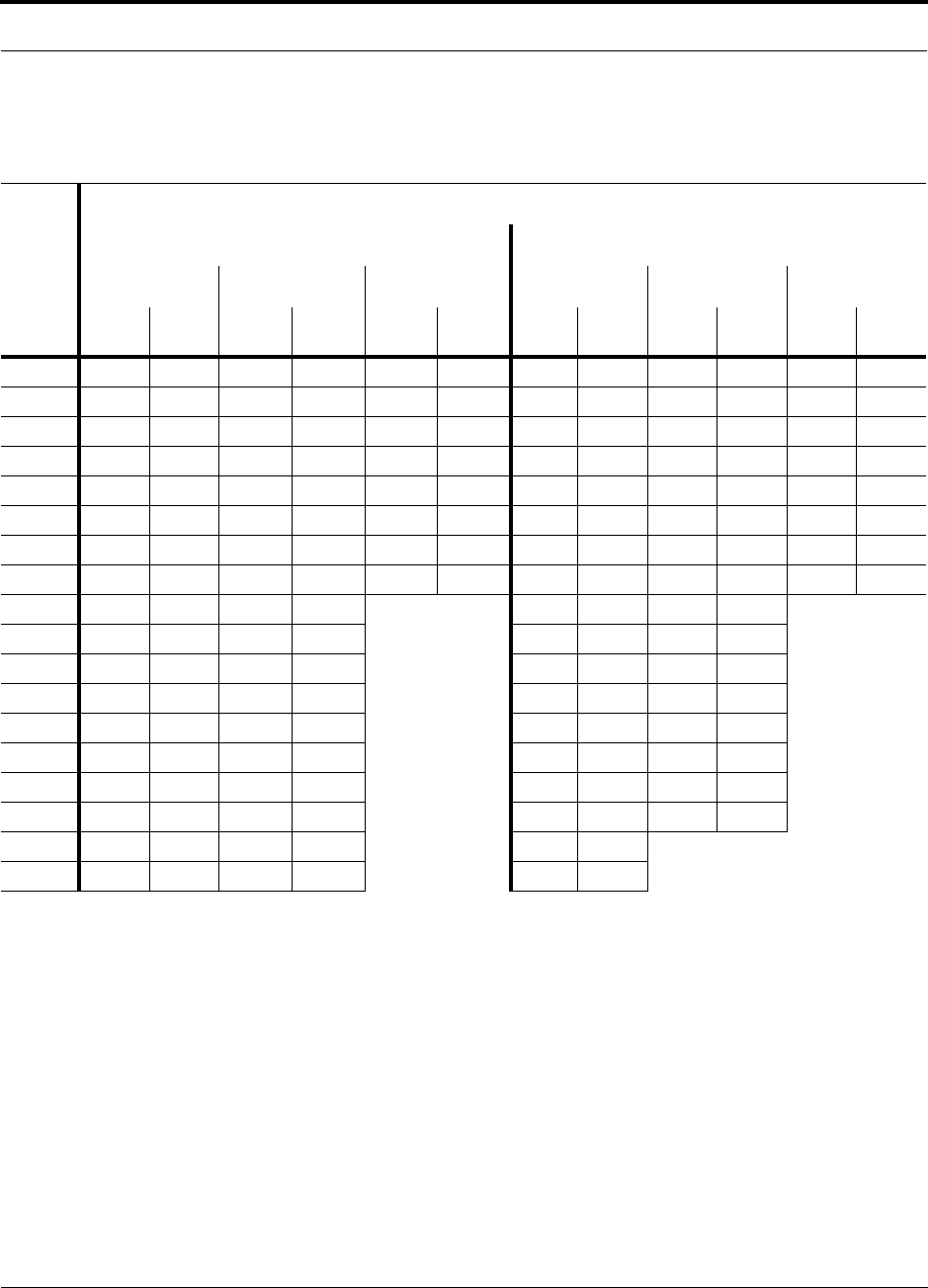
PN 9000-10 Help Hot Line (U.S. only): 1-800-530-9960 5-15
620021-0 Rev. A
800 MHz Cellular/1900 MHz PCS Dual Band
Table 5-16 800 MHz Cellular/1900 MHz PCS Power per Carrier
No. of
Carriers
Recommended Maximum Output Power per Carrier at RAU (dBm)
800 MHz Cellular 1900 MHz PCS
TDMA AMPS CDMA TDMA GSM CDMA
2 km
SMF 1 km
MMF 2 km
SMF 1 km
MMF 2 km
SMF 1 km
MMF 2 km
SMF 1 km
MMF 2 km
SMF 1 km
MMF 2 km
SMF 1 km
MMF
1 23.0 23.0 26.0 26.0 16.0 16.0 21.5 21.5 24.5 24.5 14.5 14.5
2 18.0 18.0 20.0 20.0 13.0 13.0 16.5 16.5 14.0 12.5 11.5 11.5
3 15.0 15.0 16.5 16.5 11.0 11.0 13.5 13.5 12.0 10.5 9.5 9.5
4 13.0 13.0 13.5 13.5 10.0 10.0 11.5 11.5 10.5 9.5 8.5 8.5
5 11.5 11.5 12.0 12.0 9.0 9.0 10.0 10.0 9.5 8.5 7.5 7.5
6 10.5 10.5 10.5 10.5 8.0 8.0 9.0 9.0 9.0 7.5 6.5 6.5
7 9.5 9.5 9.5 9.5 7.5 7.5 8.0 8.0 8.5 7.0 6.0 6.0
8 8.5 8.5 8.5 8.5 7.0 7.0 7.0 7.0 7.5 6.5 5.5 5.5
9 8.0 8.0 8.0 8.0 6.5 6.5 7.0 6.0
10 7.5 7.5 7.0 7.0 6.0 6.0 6.5 6.0
11 7.0 7.0 7.0 7.0 5.5 5.5 6.0 5.5
12 6.5 6.5 6.5 6.5 5.0 5.0 5.5 5.0
13 6.5 6.5 6.0 6.0 5.0 5.0 5.0 5.0
14 6.0 6.0 5.5 5.5 4.5 4.5 5.0 4.5
15 5.5 5.5 5.5 5.5 4.0 4.0 4.5 4.5
16 5.5 5.5 5.0 5.0 4.0 4.0 4.0 4.0
20 4.5 4.5 4.0 4.0 3.0 3.0
30 2.5 2.5 2.0 2.0 1.0 1.0

5-16 InterReach Unison Accel Installation, Operation, and Reference Manual PN 9000-10
620021-0 Rev. A
Allowing for Future Capacity Growth
Sometimes a Unison deployment initially is used to enhance coverage. Later that
same system may also need to provide increased capacity. Thus, the initial deploy-
ment might only transmit two carriers but need to transmit four carriers later. There
are two options for dealing with this scenario:
1. Design the initial coverage with a maximum power per carrier for four carriers.
2. Design the initial coverage for two carriers but leave RAU ports on the Hubs
unused. These ports can be used later if coverage holes are discovered once the
power per carrier is lowered to accommodate the two additional carriers.
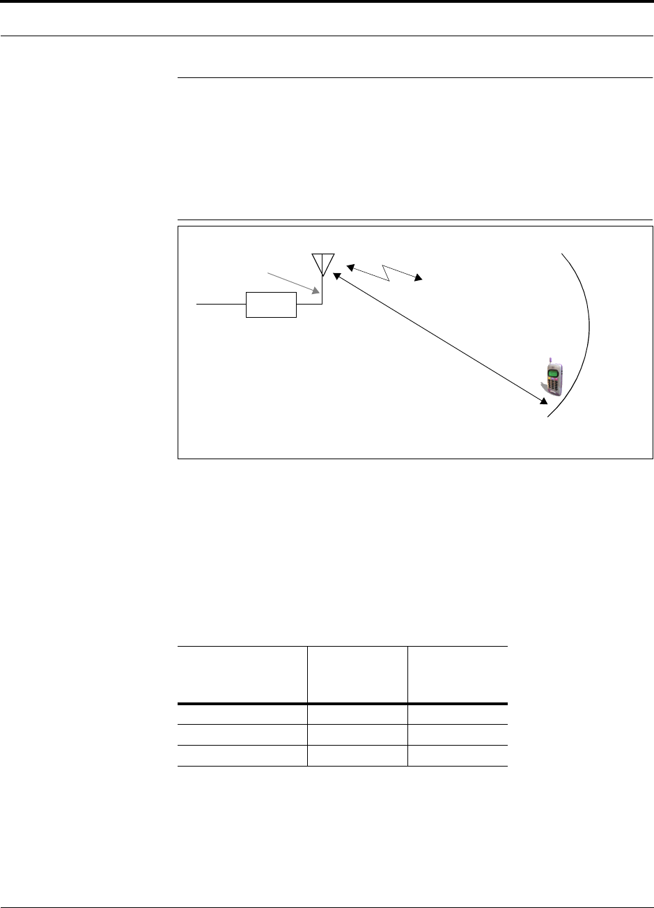
PN 9000-10 Help Hot Line (U.S. only): 1-800-530-9960 5-17
620021-0 Rev. A
5.2 Estimating RF Coverage
The maximum power per carrier (based on the number and type of RF carriers that
are being transmitted) and the minimum acceptable received power at the wireless
device (i.e., RSSI, the design goal) establish the RF link budget, and consequently the
maximum acceptable path loss between the antenna and the wireless device.
Figure 5-1 Determining Path Loss between the Antenna and the Wireless Device
(P + Lcoax + G) – RSSI = PL (1)
The path loss (PL) is the loss in decibels (dB) between the antenna and the wireless
device. The distance, d, from the antenna corresponding to this path loss can be calcu-
lated using the path loss equations in Section 5.2.1 and in Section 5.2.2.
Coaxial cable is used to connect the RAU to an antenna. The following table lists
coaxial cable loss for various cable lengths.
Table 5-17 Coaxial Cable Losses
Length of Cable
(.195 in. diameter)
Loss at
800 MHz
(dB)
Loss at
1900 MHz
(dB)
0.9 m (3 ft) 0.6 0.8
1.8 m (6 ft) 1.0 1.5
3.0 m (10 ft) 1.5 2.3
RAU
P = power per d
Antenna and Gain (G)
RSSI = power at the
wireless device
carrier from the RAU
Coax

5-18 InterReach Unison Accel Installation, Operation, and Reference Manual PN 9000-10
620021-0 Rev. A
5.2.1 Path Loss Equation
Indoor path loss obeys the distance power law1 in equation (2):
PL = 20log(4πd0f/c) + 10nlog(d/d0) + Χs(2)
where:
• PL is the path loss at a distance, d, from the antenna (the distance between the
antenna that is connected to the RAU and the point where the RF signal
decreases to the minimum acceptable level at the wireless device).
• d is the distance expressed in meters
•d
0 is usually taken as 1 meter of free-space.
• f is the operating frequency in hertz.
• c is the speed of light in a vacuum (3.0 × 10⁸ m/sec).
• n is the path loss exponent and depends on the building “clutter”.
•Χs is a normal random variable that depends on partition losses inside the build-
ing, and therefore, depends on the frequency of operation.
As a reference, the following table gives estimates of signal loss for some RF barriers.1
1. Rappaport, Theodore S. Wireless Communications, Principles, and Practice. Prentice Hall PTR, 1996.
Table 5-18 Average Signal Loss of Common Building Materials
Partition Type Loss (dB)
@ <2 GHz Frequency (MHz)
Metal wall 26 815
Aluminum siding 20 815
Foil insulation 4 815
Cubicle walls 1.4 900
Concrete block wall 13 1300
Concrete floor 10 1300
Sheetrock 1 to 2 1300
Light machinery 3 1300
General machinery 7 1300
Heavy machinery 11 1300
Equipment racks 7 1300
Assembly line 6 1300
Ceiling duct 5 1300
Metal stairs 5 1300

PN 9000-10 Help Hot Line (U.S. only): 1-800-530-9960 5-19
620021-0 Rev. A
5.2.2 Coverage Distance
Equations (1) and (2), on pages 5-17 and 5-18, respectively, can be used to estimate
the distance from the antenna to where the RF signal decreases to the minimum
acceptable level at the wireless device.
Equation (2) can be simplified to:
PL(d) = 20log(4πf/c) + PLSlog(d) (3)
where PLS (path loss slope) is chosen to account for the building’s environment.
Because different frequencies penetrate partitions with different losses, the value of
PLS will vary depending on the frequency.
Table 5-19 shows estimated path loss slope (PLS) for various environments that have
different “clutter” (i.e., objects that attenuate the RF signals, such as walls, partitions,
stairwells, equipment racks, etc.)
For simplicity, Equation (3) can be used to estimate the coverage distance of an
antenna that is connected to an RAU, for a given path loss, frequency, and type of
in-building environment.
Table 5-19 Estimated Path Loss Slope for Different In-Building Environments
Environment Type Example PLS for
800/900 MHz PLS for
1800/1900 MHz
Open Environment with very few
RF obstructions
Parking Garage, Convention Center 33.7 30.1
Moderately Open Environment
with low-to-medium amount of RF
obstructions
Warehouse, Airport, Manufacturing 35 32
Mildly Dense Environment with
medium-to-high amount of RF
obstructions
Retail, Office Space with approxi-
mately 80% cubicles and 20% hard
walled offices
36.1 33.1
Moderately Dense Environment
with medium-to-high amount of RF
obstructions
Office Space with approximately
50% cubicles and 50% hard walled
offices
37.6 34.8
Dense Environment with large
amount of RF obstructions
Hospital, Office Space with approxi-
mately 20% cubicles and 80% hard
walled offices
39.4 38.1

5-20 InterReach Unison Accel Installation, Operation, and Reference Manual PN 9000-10
620021-0 Rev. A
Table 5-20 gives the value of the first term of Equation (3) (i.e., (20log(4πf/c)) for
various frequency bands.
Table 5-20 Frequency Bands and the Value of the first Term in Equation (3)
Band (MHz) Mid-Band
Frequency
(MHz) 20log(4πf/c)Uplink Downlink
800 MHz Cellular 824–849 869–894 859 31.1
800 MHz iDEN 806–824 851–869 837.5 30.9
900 MHz GSM 890–915 935–960 925 31.8
900 MHz EGSM 880–915 925–960 920 31.7
1800 MHz DCS 1710–1785 1805–1880 1795 37.5
1800 MHz CDMA (Korea) 1750–1780 1840–1870 1810 37.6
1900 MHz PCS 1850–1910 1930–1990 1920 38.1
2.1 GHz UMTS 1920–1980 2110–2170 2045 38.7
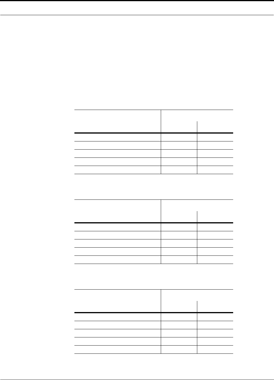
PN 9000-10 Help Hot Line (U.S. only): 1-800-530-9960 5-21
620021-0 Rev. A
For reference, Tables 5-21 through 5-27 show the distance covered by an antenna for
various in-building environments. The following assumptions were made:
• Path loss Equation (3)
• 6 dBm output per carrier at the RAU output
• 3 dBi antenna gain
• RSSI = –85 dBm (typical for narrowband protocols, but not for spread-spec-
trum protocols)
Table 5-21 Approximate Radiated Distance from Antenna
for 800 MHz Cellular Applications
Environment Type
Distance from Antenna
Meters Feet
Open Environment 73 241
Moderately Open Environment 63 205
Mildly Dense Environment 55 181
Moderately Dense Environment 47 154
Dense Environment 39 129
Table 5-22 Approximate Radiated Distance from Antenna
for 800 MHz iDEN Applications
Facility
Distance from Antenna
Meters Feet
Open Environment 75 244
Moderately Open Environment 64 208
Mildly Dense Environment 56 184
Moderately Dense Environment 48 156
Dense Environment 40 131
Table 5-23 Approximate Radiated Distance from Antenna
for 900 MHz GSM Applications
Facility
Distance from Antenna
Meters Feet
Open Environment 70 230
Moderately Open Environment 60 197
Mildly Dense Environment 53 174
Moderately Dense Environment 45 148
Dense Environment 38 125
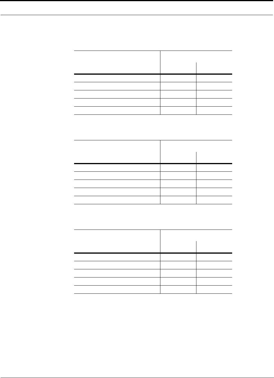
5-22 InterReach Unison Accel Installation, Operation, and Reference Manual PN 9000-10
620021-0 Rev. A
Table 5-24 Approximate Radiated Distance from Antenna
for 900 MHz EGSM Applications
Facility
Distance from Antenna
Meters Feet
Open Environment 70 231
Moderately Open Environment 60 197
Mildly Dense Environment 53 174
Moderately Dense Environment 45 149
Dense Environment 38 125
Table 5-25 Approximate Radiated Distance from Antenna
for 1800 MHz DCS Applications
Facility
Distance from Antenna
Meters Feet
Open Environment 75 246
Moderately Open Environment 58 191
Mildly Dense Environment 50 166
Moderately Dense Environment 42 137
Dense Environment 30 100
Table 5-26 Approximate Radiated Distance from Antenna
for 1800 MHz CDMA (Korea) Applications
Facility
Distance from Antenna
Meters Feet
Open Environment 75 247
Moderately Open Environment 58 191
Mildly Dense Environment 51 167
Moderately Dense Environment 42 138
Dense Environment 30 100
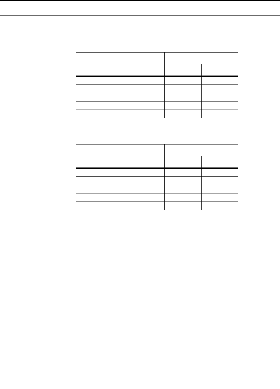
PN 9000-10 Help Hot Line (U.S. only): 1-800-530-9960 5-23
620021-0 Rev. A
Table 5-27 Approximate Radiated Distance from Antenna
for 1900 MHz PCS Applications
Facility
Distance from Antenna
Meters Feet
Open Environment 72 236
Moderately Open Environment 56 183
Mildly Dense Environment 49 160
Moderately Dense Environment 40 132
Dense Environment 29 96
Table 5-28 Approximate Radiated Distance from Antenna
for 2.1 GHz UMTS Applications
Facility
Distance from Antenna
Meters Feet
Open Environment 69 226
Moderately Open Environment 54 176
Mildly Dense Environment 47 154
Moderately Dense Environment 39 128
Dense Environment 28 93

5-24 InterReach Unison Accel Installation, Operation, and Reference Manual PN 9000-10
620021-0 Rev. A
5.2.3 Examples of Design Estimates
Example Design Estimate for an 800 MHz TDMA Application
1. Design goals:
• Cellular (859 MHz = average of the lowest uplink and the highest downlink
frequency in 800 MHz Cellular band)
• TDMA provider
• 12 TDMA carriers in the system
• –85 dBm design goal (to 95% of the building) — the minimum received power
at the wireless device
• Base station with simplex RF connections
2. Power Per Carrier: The tables in Section 5.1, “Maximum Output Power per
Carrier at RAU,” on page 5-3 provide maximum power per carrier information.
The 800 MHz TDMA table (on page 5-5) indicates that Unison can support 12
carriers with a recommended maximum power per carrier of 7.5 dBm. The input
power should be set to the desired output power minus the system gain.
3. Building information:
• 8 floor building with 9,290 sq. meters (100,000 sq. ft.) per floor; total 74,322
sq. meters (800,000 sq. ft.)
• Walls are sheetrock construction; suspended ceiling tiles
• Antennas used will be omni-directional, ceiling mounted
• Standard office environment, 50% hard wall offices and 50% cubicles
4. Link Budget: In this example, a design goal of –85 dBm is used. Suppose 3 dBi
omni-directional antennas are used in the design. Then, the maximum RF propa-
gation loss should be no more than 95.5 dB (7.5 dBm + 3 dBi + 85 dBm) over
95% of the area being covered. It is important to note that a design goal such as
–85 dBm is usually derived taking into account multipath fading and log-normal
shadowing characteristics. Thus, this design goal will only be met “on average”
over 95% of the area being covered. At any given point, a fade may bring the sig-
nal level underneath the design goal.
Note that this method of calculating a link budget is only for the downlink path.
For information to calculate link budgets for both the downlink and uplink paths,
see Section 5.4 on page 5-29.
5. Path Loss Slope: For a rough estimate, Table 5-19, “Estimated Path Loss Slope for
Different In-Building Environments” on page 5-19, shows that a building with 50%
hard wall offices and 50% cubicles, at 859 MHz, has an approximate path loss slope
(PLS) of 37.6. Given the RF link budget of 95.5 dB, the distance of coverage from
each RAU will be 52 meters (170.6 ft). This corresponds to a coverage area of
8,494 sq. meters (91,425 sq. ft.) per RAU (see Section 5.2.1 for details on path loss
estimation). For this case we assumed a circular radiation pattern, though the actual
area covered will depend upon the pattern of the antenna and the obstructions in the
facility.

PN 9000-10 Help Hot Line (U.S. only): 1-800-530-9960 5-25
620021-0 Rev. A
Equipment Required: Since you know the building size, you can now estimate
the Unison equipment quantities that will be needed. Before any RF levels are
tested in the building, you can estimate that 2 antennas per level will be needed.
This assumes no propagation between floors. If there is propagation, you may not
need antennas on every floor.
a. 2 antennas per floor × 8 floors = 16 RAUs
b. 16 RAUs ÷ 8 (maximum 8 RAUs per Expansion Hub) = 2 Expansion Hubs
c. 2 Expansion Hubs ÷ 4 (maximum 4 Expansion Hubs per Main Hub) = 1 Main
Hub
Check that the Cat-5 cable distances are as recommended. If the distances differ,
use the tables in Section 5.3, “System Gain,” on page 5-28 to determine system
gains or losses. The path loss may need to be recalculated to assure adequate sig-
nal levels in the required coverage distance.
The above estimates assume that all cable length requirements are met. If Hubs can-
not be placed so that the RAUs are within the distance requirement, additional Hubs
may need to be placed closer to the required RAUs locations.
An RF Site Survey and Building Evaluation is required to accurately establish the
Unison equipment quantities required for the building. The site survey measures the
RF losses within the building to determine the actual PLS, which will be used in the
final path loss formula to determine the actual requirements of the Unison system.

5-26 InterReach Unison Accel Installation, Operation, and Reference Manual PN 9000-10
620021-0 Rev. A
Example Design Estimate for an 1900 MHz CDMA Application
1. Design goals:
• PCS (1920 MHz = average of the lowest uplink and the highest downlink fre-
quency in 1900 MHz PCS band)
• CDMA provider
• 8 CDMA carriers in the system
• –85 dBm design goal (to 95% of the building) — the minimum received power
at the wireless device
• Base station with simplex RF connections
2. Power Per Carrier: The tables in Section 5.1, “Maximum Output Power per
Carrier at RAU,” on page 5-3 provide maximum power per carrier information.
The 1900 MHz CDMA table (on page 5-12) indicates that Unison can support 8
carriers with a recommended maximum power per carrier of 6.5 dBm. The input
power should be set to the desired output power minus the system gain.
3. Building information:
• 16 floor building with 9,290 sq. meters (100,000 sq. ft.) per floor; total
148,640 sq. meters (1,600,000 sq. ft.)
• Walls are sheetrock construction; suspended ceiling tiles
• Antennas used will be omni-directional, ceiling mounted
• Standard office environment, 80% hard wall offices and 20% cubicles
4. Link Budget: In this example, a design goal of –85 dBm is used. Suppose 3 dBi
omni-directional antennas are used in the design. Then, the maximum RF propa-
gation loss should be no more than 94.5 dB (6.5 dBm + 3 dBi + 85 dBm) over
95% of the area being covered. It is important to note that a design goal such as
–85 dBm is usually derived taking into account multipath fading and log-normal
shadowing characteristics. Thus, this design goal will only be met “on average”
over 95% of the area being covered. At any given point, a fade may bring the sig-
nal level underneath the design goal.
Note that this method of calculating a link budget is only for the downlink path.
For information to calculate link budgets for both the downlink and uplink paths,
see Section 5.4 on page 5-29.
5. Path Loss Slope: For a rough estimate, Table 5-19, “Estimated Path Loss Slope for
Different In-Building Environments” on page 5-19, shows that a building with 80%
hard wall offices and 20% cubicles, at 1920 MHz, has an approximate path loss
slope (PLS) of 38.1. Given the RF link budget of 94.5 dB, the distance of coverage
from each RAU will be 30.2 meters (99 ft). This corresponds to a coverage area
of 2,868 sq. meters (30,854 sq. ft.) per RAU (see Section 5.2.1 for details on path
loss estimation). For this case we assumed a circular radiation pattern, though the
actual area covered will depend upon the pattern of the antenna and the obstructions
in the facility.

PN 9000-10 Help Hot Line (U.S. only): 1-800-530-9960 5-27
620021-0 Rev. A
6. Equipment Required: Since you know the building size, you can now estimate
the Unison equipment quantities that will be needed. Before any RF levels are
tested in the building, you can estimate that 4 antennas per level will be needed.
This assumes no propagation between floors. If there is propagation, you may not
need antennas on every floor.
a. 4 antennas per floor × 16 floors = 64 RAUs
b. 64 RAUs ÷ 8 (maximum 8 RAUs per Expansion Hub) = 8 Expansion Hubs
c. 8 Expansion Hubs ÷ 4 (maximum 4 Expansion Hubs per Main Hub) = 2 Main
Hub
Check that the MMF and Cat-5 cable distances are as recommended. If the dis-
tances differ, use the tables in Section 5.3, “System Gain,” on page 5-28 to deter-
mine system gains or losses. The path loss may need to be recalculated to assure
adequate signal levels in the required coverage distance.
The above estimates assume that all cable length requirements are met. If Hubs can-
not be placed so that the RAUs are within the distance requirement, additional Hubs
may need to be placed closer to the required RAUs locations.
An RF Site Survey and Building Evaluation is required to accurately establish the
Unison equipment quantities required for the building. The site survey measures the
RF losses within the building to determine the actual PLS, which will be used in the
final path loss formula to determine the actual requirements of the Unison system.

5-28 InterReach Unison Accel Installation, Operation, and Reference Manual PN 9000-10
620021-0 Rev. A
5.3 System Gain
The system gain can be decreased from 15 dB to 0 dB gain in 1 dB increments and
the uplink and downlink gains of each RAU can be independently decreased by
10 dB in one step using AdminManager or OpsConsole.
5.3.1 System Gain (Loss) Relative to ScTP Cable Length
The recommended minimum length of ScTP cable is 10 meters (33 ft) and the recom-
mended maximum length is 100 meters (328 ft). The system should not be operated
with ScTP cable that is less than 10 meters (33 ft) in length, system performance will
be greatly compromised. If the ScTP cable is longer than 100 meters (328 ft), the gain
of the system will decrease, as shown in Table 5-29.
Table 5-29 System Gain (Loss) Relative to ScTP Cable Length
ScTP Cable
Length
Typical change in system gain (dB)
Downlink Uplink
800 MHz TDMA/AMPS and CDMA; 900 MHz GSM and
EGSM; and iDEN
110 m / 361 ft –1.0 –0.7
120 m / 394 ft –3.2 –2.4
130 m / 426 ft –5.3 –4.1
140 m / 459 ft –7.5 –5.8
150 m / 492 ft –9.7 –7.6
1800 MHz GSM (DCS); 1900 MHz TDMA, CDMA, and GSM
110 m / 361 ft –1.0 –0.7
120 m / 394 ft –4.0 –2.4
130 m / 426 ft –6.4 –4.1
140 m / 459 ft –8.8 –5.8
150 m / 492 ft –11.3 –7.6
2.1 GHz UMTS
110 m / 361 ft –1.0 –0.7
120 m / 394 ft –3.2 –2.4
130 m / 426 ft –5.3 –4.1
140 m / 459 ft –7.5 –5.8
150 m / 492 ft –9.7 –7.6
PN 9000-10 Help Hot Line (U.S. only): 1-800-530-9960 5-29
620021-0 Rev. A
5.4 Link Budget Analysis
A link budget is a methodical way to account for the gains and losses in an RF system
so that the quality of coverage can be predicted. The end result can often be stated as
a “design goal” in which the coverage is determined by the maximum distance from
each RAU before the signal strength falls beneath that goal.
One key feature of the link budget is the maximum power per carrier discussed in
Section 5.1. While the maximum power per carrier is important as far as emissions
and signal quality requirements are concerned, it is critical that the maximum signal
into the Main Hub never exceed 1W (+30 dBm). Composite power levels above this
limit will cause damage to the Main Hub.
WARNING: Exceeding the maximum input power of 1W (+30 dBm)
could cause permanent damage to the Main Hub.

5-30 InterReach Unison Accel Installation, Operation, and Reference Manual PN 9000-10
620021-0 Rev. A
5.4.1 Elements of a Link Budget for Narrowband Standards
The link budget represents a typical calculation that might be used to determine how
much path loss can be afforded in a Unison design. This link budget analyzes both the
downlink and uplink paths. For most configurations, the downlink requires lower
path loss and is therefore the limiting factor in the system design. It is for this reason
that a predetermined “design goal” for the downlink is sufficient to predict coverage
distance.
The link budget is organized in a simple manner: the transmitted power is calculated,
the airlink losses due to fading and body loss are summed, and the receiver sensitivity
(minimum level a signal can be received for acceptable call quality) is calculated. The
maximum allowable path loss (in dB) is the difference between the transmitted
power, less the airlink losses, and the receiver sensitivity. From the path loss, the
maximum coverage distance can be estimated using the path loss formula presented
in Section 5.2.1.
Table 5-30 provides link budget considerations for narrowband systems.
Table 5-30 Link Budget Considerations for Narrowband Systems
Consideration Description
BTS Transmit Power The power per carrier transmitted from the base station output
Attenuation between
BTS and Unison
This includes all losses: cable, attenuator, splitter/combiner, and so forth.
On the downlink, attenuation must be chosen so that the maximum power per carrier going into the
Main Hub does not exceed the levels given in Section 5.1.
On the uplink, attenuation is chosen to keep the maximum uplink signal and noise level low enough
to prevent base station alarms but small enough not to cause degradation in the system sensitivity.
If the Unison noise figure minus the attenuation is at least 10 dB higher than the BTS noise figure,
the system noise figure will be approximately that of Unison alone. See Section 5.5 for ways to inde-
pendently set the uplink and downlink attenuations between the base station and Unison.
Antenna Gain The radiated output power includes antenna gain. For example, if you use a 3 dBi antenna at the
RAU that is transmitting 0 dBm per carrier, the effective radiated power (relative to an isotropic
radiator) is 3 dBm per carrier.
BTS Noise Figure This is the effective noise floor of the base station input (usually base station sensitivity is this effec-
tive noise floor plus a certain C/I ratio).
Unison Noise Figure This is Unison’s uplink noise figure, which varies depending on the number of Hubs and RAUs, and
the frequency band. Unison’s uplink noise figure is specified for a 1-1-4 configuration. Thus, the
noise figure for a Unison system (or multiple systems whose uplink ports are power combined) will
be NF(1-1-4) + 10*log(# of Hubs). This represents an upper-bound because the noise figure is lower
if any of the Hub’s RAU ports are not used.