ADC ADDC1 ADC1 Manual Rev C User To The 52a10c3c 7253 4061 A48b 78e9861c5bf9
User Manual: ADC ADDC1 to the manual
Open the PDF directly: View PDF ![]() .
.
Page Count: 34
ADC1 Instruction Manual Page 1
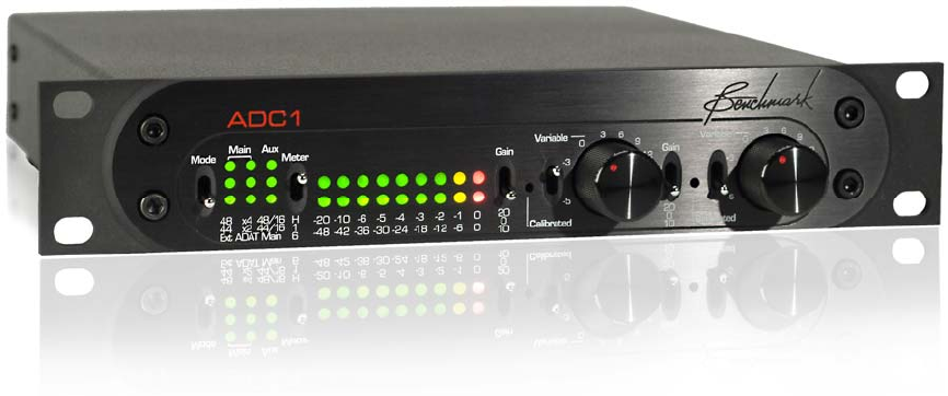
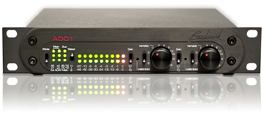
Benchmark ADC1
Instruction Manual
2-Channel 24-bit 192-kHz
Audio Analog-to-Digital Converter

ADC1 Instruction Manual Page 2
Federal Communications
Commission (FCC) Notice
(U.S. Only)
NOTICE: This equipment has been tested and
found to comply with the limits for a Class B
digital device, pursuant to Part 15 of the FCC
Rules. These limits are designed to provide
reasonable protection against harmful
interference in a residential installation. This
equipment generates, uses, and can radiate
radio frequency energy and, if not installed
and used in accordance with the instructions,
may cause harmful interference to radio
communications. However, there is no
guarantee that interference will not occur in a
particular installation. If this equipment does
cause harmful interference to radio or
television reception, which can be determined
by turning the equipment off and on, the user
is encouraged to try to correct the
interference by one or more of the following
measures:
• Reorient or relocate receiving antenna.
• Increase the separation between the
equipment and receiver.
• Connect the equipment into an outlet on a
circuit different from that to which the
receiver is connected.
• Consult the dealer or an experienced
radio/TV technician for help.
This device complies with Part 15 of the FCC
rules. Operation is subject to the following
two conditions:
1. This device may not cause harmful
interference.
2. This device must accept any interference
received including interference that may
cause undesired operation.
Instructions to Users: This equipment
complies with the requirements of FCC
(Federal Communication Commission)
equipment provided that following conditions
are met:
1. XLR Digital Output: Shielded 110-Ohm
AES/EBU digital audio cable with
connector shell bonded to shield must be
used.
2. BNC Digital Connections: Shielded 75-
Ohm coaxial cable must be used.
NOTICE: Changes or modifications not
expressly approved by the party responsible
for compliance could void the user's authority
to operate the equipment.
Safety Information
Do NOT service or repair this product unless
properly qualified. Only a qualified technician
should perform repairs.
For continued fire hazard protection, fuses
should be replaced ONLY with the exact value
and type as indicated on the rear panel.
Do NOT substitute parts or make any
modifications without the written approval of
Benchmark Media Systems, Inc. Doing so
may create safety hazards and void the
warranty.
ADC1 Instruction Manual Page 3
Contents
Overview 4
Features 6
Connections 7
Balanced Analog Line Inputs 7
Clock Reference Input 7
Digital Outputs 8
AES/EBU XLR Output 8
Optical Output 8
SPDIF/AES BNC Main and Aux Outputs 9
Word Clock Reference Output 10
AC Power Entry Connector 10
Fuse Holder 10
Operation 11
Mode Switch and Display 11
Programming the Outputs 11
Locking to an External Clock Source 11
Selecting a Fixed Frequency Using the
Internal Clock Source 12
Reading Sample Rates off of the Mode
Display 12
Programming the Aux Output 12
ADAT or AES/EBU on the Optical Output 13
Resetting the ADC1 to Factory Default
Settings 13
Meter Display 13
Adjusting Input Gain 14
First Stage Gain 14
Second Stage Gain Controls 14
Rack Mounting 15
Using ADAT S/MUX 16
UltraLock™ … What is It? 17
Performance 20
Frequency Response 20
Inter-Channel Phase Response 21
THD+N vs. Level, 1 KHz 22
32K B-H FFT, Idle Channel Noise 23
32K B-H FFT, -3 dBFS, 1 KHz 24
32K B-H FFT, -3 dBFS, 10 KHz 25
Specifications 26
Analog Audio Inputs 26
Clock Reference Input 26
Worldclock Reference Output 26
Digital Audio Outputs 27
Audio Performance 28
Group Delay (Latency) 29
LED Status Indicators 29
AC Power Requirements 30
Dimensions 30
Certificate of Compliance 31
Warranty 32
Extended Warranty 33
Copyright and Contact Information 34
ADC1 Instruction Manual Page 4
Overview
The ADC1 is a reference-quality, 2-channel
192-kHz 24-bit audio analog-to-digital
converter featuring Benchmark’s UltraLock™
technology. The ADC1 is designed for
maximum transparency. It is well suited for
the most demanding applications in studios
and mastering facilities. A rugged and
compact half-wide 1 RU enclosure also makes
the ADC1 an excellent choice for location
recording, broadcast facilities, and mobile
rigs. The internal power supply supports all
international voltages and has generous
margins for over and under voltage
conditions.
The ADC1 achieves outstanding performance
over a wide range of input levels. Each
channel has a 41-detent variable gain control,
a 10-turn calibration trimmer, and a 3-
position first-stage gain switch (0, 10, and 20
dB). Each channel has a two-position toggle
switch that selects either the 41-detent pot or
the 10-turn trimmer. Both the pot and the
trimmer have a 20 dB adjustment range. In
combination with the first-stage gain switch,
these controls provide exceptional SNR and
THD+N performance over a 40 dB adjustment
range. The 10-turn calibration trimmer may
be used to calibrate the ADC1 to precise
studio reference levels. It may also be used to
optimize the gain-staging between a
microphone preamplifier and the ADC1.
The ADC1 has four digital outputs (1 balanced
XLR, 2 coaxial, and 1 optical). The optical
output supports AES, ADAT, and ADAT
S/MUX. The two coaxial outputs (Main and
Aux) can operate simultaneously at different
word lengths and even at different sample
rates. The ADC1 has the flexibility to allow
simultaneous high-resolution and low-
resolution recordings. For example, the main
outputs of the ADC1 can be set to 192 kHz
24-bits while the auxiliary output is set to
44.1 kHz 16-bits for a safety backup or CDR
demo recording. Both the Main and Aux
Outputs originate from the same A/D
converter. All outputs are professional format.
The ADC1 has a Word Clock output that
follows the sample rate of the Main Outputs.
The Word Clock output is active in all modes
of operation.
A multi-format clock input automatically
recognizes AES/EBU, SPDIF, Word Clock, or
Super Clock signals. This clock input is used
to synchronize the Main Outputs. If desired,
the Main Outputs may be driven from internal
sources. The ADC1 will automatically revert to
an internal clock source when the external
clock is lost.
The ADC1 has two clock modes: Auto and
Internal. Both modes support 44.1, 48, 88.2,
96, 176.4 and 192 kHz.
ADC1 Instruction Manual Page 5
The Auto mode allows the ADC1 to lock to an
external clock reference. In Auto mode, the
ADC1 will follow changes in sample rate,
and/or changes in the type of reference signal
(AES, SPDIF, word clock, or super clock).
When a clock reference is not available, the
Internal mode must be used, and a sample-
rate must be selected (44.1, 48, 88.2, 96,
176.4, or 192 kHz). When the Internal mode
is active, the ADC1 is acting as clock master,
will only operate at the selected sample rate,
and will ignore any signal at the clock
reference input. If Internal mode is used, all
devices connected to the ADC1 digital outputs
will need to be configured to lock to the
ADC1. Use the clock output on the back of the
ADC1 if the connected devices require word
clock.
The Benchmark UltraLock system is 100%
jitter immune. The A/D conversion clock is
totally isolated from the AES/EBU, SPDIF,
ADAT, WC, and super clock interfaces. This
topology outperforms two-stage PLL designs.
In fact, no jitter-induced artifacts can be
detected using an Audio Precision System 2
Cascade test set. Measurement limits include
detection of artifacts as low as -140 dBFS,
application of jitter amplitudes as high as
12.75 unit intervals (UI) and application of
jitter over a frequency range of 2 Hz to 200
kHz. A poor-quality clock reference will not
degrade the jitter performance of the ADC1.
In addition, the AES/EBU receiver IC has been
selected for its ability to decode signals in the
presence of very high levels of jitter. The
Benchmark UltraLock system delivers
consistent performance under all operating
conditions.
The ADC1 is designed to perform gracefully in
the presence of errors and interruptions at
the clock reference input. The ADC1 follows
an audio-always design philosophy. Audio is
present at the outputs shortly after applying
power to the unit. The ADC1 will even lock to
and AES/EBU signal that has its sample-rate
status bits set incorrectly. Sample rate is
determined by measuring the incoming
signal. Lack of sample rate status bits or
incorrectly set status bits will not cause loss
of audio.
The ADC1 is phase accurate between
channels, and between other ADC1 boxes
when locked to AES/EBU or word clock
reference signals. The word clock output from
one ADC1 may be connected to the clock
input on another ADC1 to expand the number
of phase-accurate conversion channels.
ADC1 Instruction Manual Page 6
Features
• Two analog-to-digital conversion channels
• Two XLR balanced analog inputs providing high-performance over a 43 dB range
• -14 dBu to +29 dBu input sensitivity range (at 0 dBFS)
• Two 0 dB, 10dB, and 20 dB first-stage gain switches (1 per channel)
• Two 41-detent gain controls with a 20 dB range (1 per channel)
• Two 10-turn gain calibration controls with a 20 dB range (1 per channel)
• Benchmark 9-segment dual-range digital LED meters
• Sample Rate LED indicators
• Conversion at 44.1, 48, 88.2, 96, 176.4, and 192 kHz
• Versatile Auto and Internal clock modes
• Multifunction clock input with auto-recognition of AES, SPDIF, Word Clock, or Super Clock
• Word Clock output
• Total jitter immunity with Benchmark’s, phase-accurate UltraLock™ technology
• Simultaneous output at two different sample rates
• Simultaneous 16 and 24-bit outputs
• Four digital outputs (1 XLR, 2 Coax, 1 optical)
• AES/EBU, ADAT, and ADAT S/MUX2, and ADAT S/MUX4 output formats
• THD+N = -104 dB, 0.00063% @ -3 dBFS input, SNR 121 dB A-weighted
• Reliable and consistent performance under all operating conditions
• Internal 115 V, 230 V, 50-60 Hz international power supply with very wide operating range
• Low radiation toroidal power transformer significantly reduces hum and line related interference
• Meets FCC Class B and CE emissions requirements
ADC1 Instruction Manual Page 7
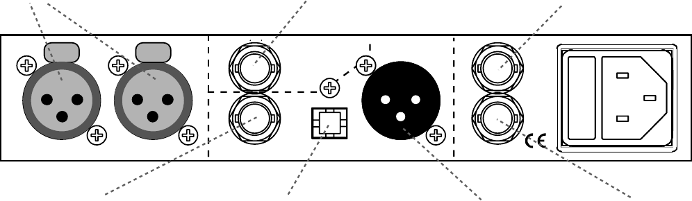
Connections
Main 24-Bit Digital Outputs
Aux 24 or 16-Bit
Digital Output
Analog Line In
AES/EBU
ADAT/SPDI F
SPDIF,
AES WC
Out
AES,
WC,
SC
Ref In
Left Right
Balanced Analog
Line Inputs (XLR)
Auxiliary Digital Output,
BNC (AES)
Clock Reference Input,
BNC (AES, Wordclock, Superclock)
Wordclock Reference
Out
p
ut, BNC
Main Digital Output,
XLR (AES /EBU)
Main Digital Output,
TOSLINK O
p
tical (ADAT /SPDIF)
Main Digital Output,
BNC (SPDIF/AES)
Balanced Analog Line Inputs
Left and Right balanced inputs use locking
Neutrik™ gold-pin female XLR jacks. These
inputs have a wide operating range. The input
sensitivity (at 0 dBFS) ranges from -20 dBu
(at maximum gain) to +29 dBu (at minimum
gain). The input impedance is 200k Ohms
balanced, and 100k Ohms unbalanced. The
high input impedance and input sensitivity,
allow direct connections from many
instrument pickups (adapter cable required).
Direct connection of piezo pickups is not
recommended as these pickups require higher
input impedances (to prevent low-frequency
roll-off problems).
• XLR pin 2 = + Audio In
• XLR pin 3 = - Audio In
• XLR pin 1 = Cable Shield (grounded
directly to the chassis to prevent internal
ground loops)
To adapt to unbalanced sources
1. Connect “+” or hot (tip on ¼ phone plug,
center pin on RCA plug) to XLR pin 2.
2. Connect ground (sleeve on ¼” phone
plug, case on RCA plug) to XLR pins 3 and
1.
Note it is best to used balanced wiring (“+”,
“-“, “shield”) and to tie the “-“and “shield” at
the unbalanced connector.
Clock Reference Input
This input auto-detects AES/EBU, SPDIF,
Word Clock, or Super Clock signals, and
automatically follows changes in sample-rate.
When Auto mode is active the ADC1 will lock
to the external clock source. Benchmark’s
UltraLock circuitry isolates the conversion
clock from any jitter present on the clock
reference. Auto Mode will not degrade the
conversion quality of the ADC1 even when
very high levels of jitter are present on the
clock reference.
ADC1 Instruction Manual Page 8
Digital Outputs
The ADC1 has four digital audio outputs:
three Main Outputs and one Aux Output.
Main Outputs
• XLR connector, balanced, AES/EBU
professional format, 24-bits
• BNC connector, un-balanced, AES/EBU
professional format, 24-bits, compatible
with most SPDIF inputs
• Optical TOSLINK connector, multi-format
(AES professional, ADAT, ADAT S/MUX II
& IV), 24-bits
Aux Output
• BNC connector, AES Professional format,
16 or 24-bits
All of the outputs are controlled by the front-
panel Mode Switch. The status of these
outputs is shown in the Mode Display
adjacent to the Mode Switch.
Three of the outputs are Main Outputs and
always operate at 24-bits. The Main Outputs
may be synchronized to an external clock
reference or may be controlled by the internal
clock. The Optical Output has two modes of
operation; AES/EBU and ADAT. The ADAT
mode supports ADAT (44.1 and 48 kHz),
ADAT S/MUX2 (88.2 and 96 kHz), and ADAT
S/MUX4 (176.4 and 192 kHz).
The Aux Output can operate asynchronously
at 44.1 or 48 kHz with a TPDF-dithered 16-bit
word length. The Aux Output is provided as a
convenience for making safety backups or
demo recordings to low-resolution 16-bit
recorders (i.e. CDR or DAT). If this low-
resolution function is not needed, the Aux
Output can be set to mirror the high-
resolution Main Outputs.
AES/EBU XLR Output
This output uses a gold-pin Neutrik™ male
XLR connector. The output is balanced and
has an output impedance of 110 Ohms. This
output is DC-isolated, transformer-coupled,
current-limited, and diode-protected. It is
designed to drive standard 4 Vpp AES signals
into a 110 Ohm load. Use 110 Ohm digital
cable when connecting this output to other
devices. The use of analog audio cables may
cause data transmission errors.
• Data Format = AES/EBU professional
format
• Word Length = 24 bits
• Sample Rate = 44.1, 48, 88.2, 96, 176.4,
or 192 kHz
• Clock Source = Internal or external
Optical Output
The Optical Output has four modes of
operation; AES/EBU, ADAT, ADAT S/MUX2,
and ADAT S/MUX4. The ADAT LED on the
front panel is illuminated whenever any of the
ADAT Modes are active. S/MUX2 and S/MUX4
are automatically enabled if required to
support the selected sample rate. S/MUX2 is
active at 88.2 or 96 kHz, S/MUX4 is active at
176.4 or 192 kHz.
The Optical Output uses what is often called a
TOSLINK, Type FO5, or 5 mm optical
connector. The ADC1 uses a special high-
bandwidth version that supports AES/EBU
digital audio at sample rates up to 192 kHz.
Please note that many optical inputs cannot
support AES/EBU or SPDIF digital audio at
sample rates above 48 kHz, others are limited
to 96 kHz. A few products (such as the
Benchmark DAC1) support 192 kHz optical
inputs. Please note that high-bandwidth
optical transmitters and receivers are not
required for ADAT, ADAT S/MUX2, or even
ADAT S/MUX4.
AES/EBU Optical Output Mode
• Data Format = AES/EBU professional
format
• Word Length = 24 bits
• Sample Rate = 44.1, 48, 88.2, 96, 176.4,
or 192 kHz
• Clock Source = Internal or external
ADC1 Instruction Manual Page 9
ADAT Optical Output Mode
• Data Format = ADAT
• Word Length = 24 bits
• Sample Rate = 44.1 or 48 kHz
• Clock Source = Internal or external
• ADAT channel assignments: 1 = Left, 2 =
Right, 3-8 = muted
ADAT S/MUX2 Optical Output
Mode
• Data Format = ADAT
• Word Length = 24 bits
• Sample Rate = 88.2 or 96 kHz
• Clock Source = Internal or external
• ADAT channel assignments *: 1 = Left a,
2 = Left b, 3 = Right a, 4 = Right b, 5-8 =
muted
* a, and b are successive samples
ADAT S/MUX4 Optical Output
Mode:
• Data Format = ADAT
• Word Length = 24 bits
• Sample Rate = 176.4 or 192 kHz
• Clock Source = Internal or external
• ADAT channel assignments **: 1 = Left a,
2 = Left b, 3 = Left c, 4 = Left d, 5 =
Right a, 6 = Right b, 7 = Right c, 8 =
Right d
** a, b, c, and d are successive samples
SPDIF/AES BNC Main and Aux
Outputs
The two BNC coaxial digital outputs use
female BNC connectors. These connectors are
securely mounted directly to the rear panel.
These are 1 Vpp unbalanced outputs with 75-
Ω source impedances. Outputs are DC-
isolated, transformer-coupled, current-
limited, and diode-protected. Use 75 Ohm
coaxial cable when connecting these outputs
to other devices. The use of 50 Ω coax is not
recommended and may cause data
transmission errors.
Many customers are more familiar with
consumer-style RCA-equipped SPDIF digital
interfaces. The ADC1 ships with BNC-to-RCA
adapters. These adapters allow easy
interfacing with consumer-style digital
interfaces. BNC to RCA coaxial cords are also
available from Benchmark.
BNC connectors are specified by the AES3-id
and SMPTE 276M standards for 75-Ω 1 Vpp
digital audio signals and are commonly used
in video production facilities and other
professional audio applications. RCA
connectors are specified by IEC 609588-3 for
75-Ω 0.5 Vpp consumer-format digital audio
signals (commonly known as SPDIF). We
have chosen to comply with the professional
standards because the BNC connectors lock
and are generally more reliable than RCA
connectors. Compliance with the 1 Vpp digital
audio standards increases the reliability of
digital connections, and often allows
increased transmission distances.
Main BNC Output
This digital data at this output is identical to
that of the Main XLR Digital Output.
• Data Format = AES/EBU professional
format
• Word Length = 24 bits
• Sample Rate = 44.1, 48, 88.2, 96, 176.4,
or 192 kHz
• Clock Source = Internal or external
Aux Output
This BNC digital output has two signals
available to it. The first is a 16-bit TPDF
auxiliary output for use with low-resolution
devices. The second signal is the Main digital
output and is identical to the data available at
the other Main digital outputs.
• Data Format = AES/EBU professional
format
• Word Length = 16 bits TPDF dithered, or
24 bits
• Sample Rate = 44.1 or 48 at 16-bits,
44.1, 48, 88.2, 96, 176.4, or 192 kHz at
24-bits
• Clock Source = Internal at 16-bits,
internal or external at 24-bits
ADC1 Instruction Manual Page 10
Word Clock Reference Output
This output provides a Word Clock signal for
use with downstream components.
AC Power Entry Connector
The AC power input uses a standard IEC type
connector. Within the USA and Canada, the
ADC1 ships with a power cord. In other
locations, a location-specific IEC style power
cord may be purchased from a local source
(including a local Benchmark dealer).
Fuse Holder
The fuse holder is built into a drawer next to
the IEC power connector. The drawer requires
two 5 x 20 mm 250 V Slo-Blo® Type fuses.
The drawer includes a voltage selection switch
with two settings: 110 and 220. Both settings
use a 0.5 Amp fuse.
The AC input has a very wide input voltage
range and can operate over a frequency
range of 50 to 60 Hz. At 110, the ADC1 will
operate normally over a range of 95 to 140
VAC. At 220, the ADC1 will operate normally
over a range of 190 to 285 VAC.
CAUTION: ALWAYS REPLACE THE FUSES
WITH THE CORRECT SIZE AND TYPE.
ADC1 Instruction Manual Page 11
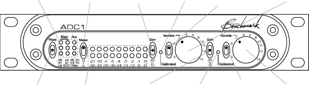
Operation
Mode Display
Mode Switch Meter Display
Meter Switch Left
First Stage Gain
Right
First Stage Gain
Left
Variable/Calibrated
Gain Switch
Right
Variable/Calibrated
Gain Switch
Left Gain
Preset
Right Gain
Preset
Left Gain
Right Gain
Mode Switch and Display
The ADC1 can be programmed to function in
a variety of conversion modes, including
sample rates, bit depths, and output formats,
using internal and/or external clock sources.
This programming is all done through the
Mode Switch. The Mode Display shows the
selected mode in a concise format.
The Mode Switch is a momentary toggle
switch. There are two ways of operating the
mode switch:
1. Press
2. Press and Hold
Pressing the Mode Switch momentarily and
then releasing it results in a particular change
to the ADC1 conversion mode, while pressing
and holding the switch results in a different
change.
To program the conversion mode
• Press the Mode Switch up repeatedly to
cycle through the clock source and sample
rate options for the Main Outputs.
• Press the Mode Switch down repeatedly to
to cycle through the sample rate and bit
depth options for the Aux Output.
• Press and hold the Mode Switch down for
approximately 3 seconds to switch
between AES/EBU and ADAT mode for the
Optical Output.
• Press and hold the Mode Switch up for
approximately 3 seconds to reset the
ADC1 to Factory Default settings.
Details about all of these actions follow.
Programming the Outputs
Pressing up repeatedly on the mode switch
cycles through the clock source and sample
rate options for the Main Outputs. The Main
Outputs can be set to operate at a fixed
frequency using the internal clock source, or
they can be set to follow and lock to an
external clock source.
Locking to an External Clock
Source
The ADC1 can sync to a variety of external
clock sources, including Word Clock, Super
Clock, AES, and SPDIF. Once the ADC1
acquires sync, it will perform conversion at
the sample rate of the external clock.
ADC1 Instruction Manual Page 12
Off = Internal Sync
On = Locked to External Sync
Flash = External Sync Selected
but Not Locked
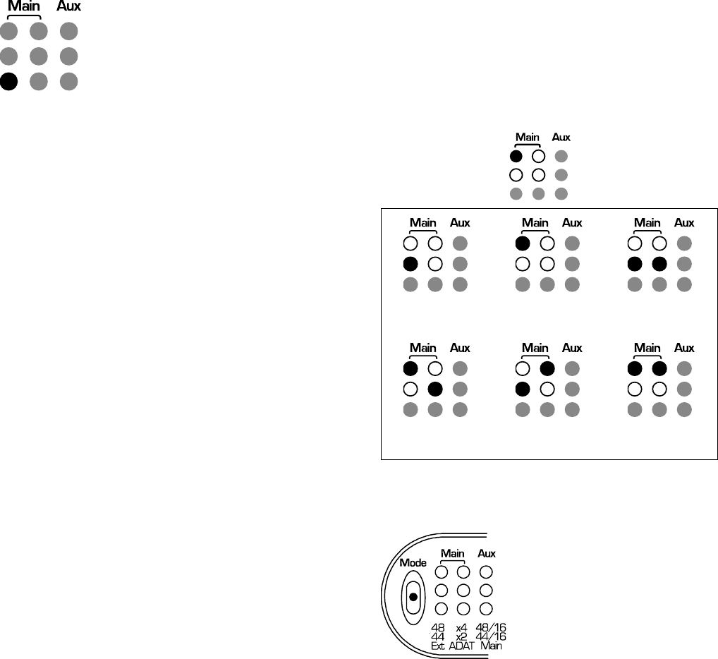
The bottom left LED in the Mode Display is
the Ext Indicator. It shows that the ADC1 is
locked to an external clock source. If the Ext
LED is off, then the ADC1 is set to operate at
a fixed sample rate using the internal clock
source. If the Ext LED is on, the ADC1 is
locked to an external clock. When locked, the
Mode Display will indicate the sample rate.
The ADC1 will automatically switch sample
rates in response to changes in the reference
sample rate. If the Ext LED is flashing, then
the ADC1 is set to sync to an external clock
source, but the ADC1 has not acquired a lock.
The ADC1 should lock in less than 5 seconds.
If the Ext LED flashes for more than 5
seconds, there is something wrong with the
clock reference. Check the connections to the
ADC1 Ref Input. The ADC1 will lock to AES,
SPDIF, WC, or Super Clock and is very
tolerant of low-level low-quality reference
signals.
To synchronize with an external
clock source
• Press up repeatedly on the Mode Switch,
cycling through the Main Output modes
until the lower left Ext LED is either on or
flashing.
Selecting a Fixed Frequency
Using the Internal Clock Source
The ADC1 can be programmed to convert at a
fixed frequency using an internal clock
source. The following sample rate frequencies
are available: 44.1, 48, 88.2, 96, 176.4, and
192 kHz. The ADC1 External Clock Input is
ignored when the internal clock source is
selected.
To select a fixed sample frequency
on the Main Outputs
• Press up repeatedly on the Mode Switch to
cycle through the available sample
frequencies until the four LEDs in the
upper left of the Mode Display match one
of the diagrams below.
Black = Lit
White = Not Lit
Gray = Irrelevant
44.1kHz 48 kHz 88.2 kHz
96 kHz 176.4 kHz 192 kHz
Reading Sample Rates off of the
Mode Display
Column one of the display has a “44” LED and
a “48” LED. These indicate sample rates of
44.1 kHz and 48 kHz respectively. Column
two has an “X2” LED and an “X4” LED. These
indicate 2x or 4x multipliers. Multiply the
sample rate shown in column one by the
multiplier shown in column two. For example,
if the 44 and X2 LEDs are on, the sample rate
is 88.2 kHz (44.1 x 2 = 88.2).
ADC1 Instruction Manual Page 13
Programming the Aux Output
The Aux Output can be programmed to mirror
the Main Outputs (bit for bit), or it can
provide an independent low-resolution copy of
the converted signal, at an independent
sample rate. Column three of the Mode
Indicator displays the Aux Output mode
setting.
Note that no matter how the Aux Output is
programmed it does not affect the Main
Outputs in any way.
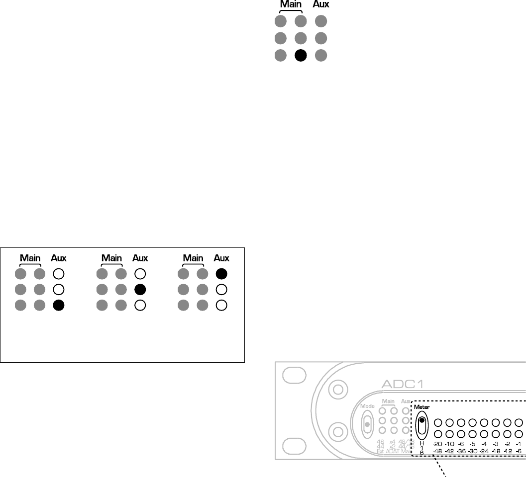
To program the Aux Output
Press down on the Mode Switch repeatedly to
cycle through the Aux Output mode settings
until the right-hand column of LEDs in the
Mode Display matches the desired mode
based on the diagrams below.
Exact Copy of
Main Outputs
(24-bit)
44.1 kHz
16-bit
48 kHz
16-bit
ADAT or AES/EBU on the
Optical Output
The Optical Output (on of the three Main
Outputs) can provide either AES/EBU or ADAT
format. The bottom LED in the middle column
of LEDs indicates what mode the Optical
Output is in.
When ADAT is active, S/MUX is automatically
enabled at all 2X and 4X sample rates (88.2
kHz, 96 kHz, 176.4 kHz, and 192 kHz).
To select between ADAT or
AES/EBU on the Optical Output
Press and hold the Mode Switch down until
the Optical Output mode LED matches the
desired mode based on the diagram below.
Off = AES/EBU on Optical
Output
On – ADAT on Optical Output
Resetting the ADC1 to Factory
Default Settings
The ADC1 can be easily reset to Factory
Default settings.
To reset the ADC1 to Factory
Default settings
• Press and hold the Mode Switch up for
approximately 3 seconds.
Meter Display
The ADC1 is equipped with a multi-function 9-
segment LED meter. The Meter Switch selects
either a 6 dB/step or 1 dB/step scale and
controls the peak-hold function. Metering is
fully-digital and is post conversion for
absolute accuracy. The units are dBFS (dB
below the level of a full-scale sine wave, or
more simply, dB below digital clip).
Meter Switch and Meters
Time constants are built into the meters so
that all transient peaks can be observed
easily. If a transient peak having a duration
as short as one digital sample occurs, an LED
will be illuminated, and will stay illuminated
long enough to be observed by the human
eye.
A peak indication mimics the action of the
needle on a peak-reading analog meter, while
the remaining LEDs will follow the
instantaneous level of the audio.
ADC1 Instruction Manual Page 14
The red 0 LED indicates that a full-scale
digital code has been reached and that digital
clipping has occurred. Full-scale events as
short as one digital sample, will light the 0
LED. Short single-sample digital clipping
events are often audible, and all 0 dBFS
events should be avoided.
The ADC1 has a very large dynamic range
(especially when operating at 24-bit output
word lengths). It is wise to use some of this
dynamic range to provide more headroom as
insurance against clipping. Leave some extra
headroom between your highest anticipated
peak and the red 0 dBFS LED.
To select the meter scale and
peak hold function
• Set the Meter Switch to “H” (up) to enable
the Peak Hold function and set the scale
to 1 dB/step.
• Set the Meter Switch to “1” (center) to
disable the Peak Hold function and set the
scale to 1 dB/step.
• Set the Meter Switch to “6” (down) to
disable the Peak Hold function and set the
scale to 6 dB/step.
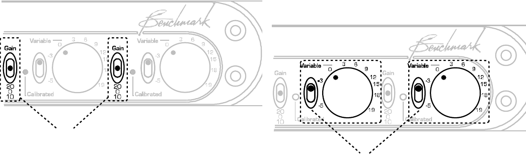
Adjusting Input Gain
Input Gain Stages
First Stage Gain
Each channel on the ADC1 is equipped with a
3-position first-stage gain switch. The first
gain stage provides exceptional noise
performance at gains of 0 dB, +10 dB, or +20
dB. This stage is followed by a second-stage
having a continuously variable gain range of
-1.3 dB to +22 dB. This gain structure
provides ultra-high performance at any gain
setting between -1.3 dB and +42 dB. The
higher gain settings will allow direct
connections from many instrument pickups
(no DI box required).
To select the first stage gain
• Set the Gain Switch to “0” (center) to
select 0 dB gain (unity gain) for the first-
stage.
• Set the Gain Switch to “10” (down) to
select 10 dB gain for the first-stage.
• Set the Gain Switch to “20” (up) to select
20 dB gain for the first-stage.
Second Stage Gain Controls
The second gain stage of each channel has a
41-detent Gain Control Knob, and a 10-turn
Gain Calibration Trimmer. Each channel also
has a 2-position Second-Stage Gain Switch.
The switch selects either the Gain Control
Knob or the Gain Calibration Trimmer. Both
controls have a useable range of
approximately -1.3 dB to +22 dB.
To use the Gain Control Knob to
adjust second stage gain
Set the Secondary Gain Switch to Variable
(up) as shown in the diagram below.
Up Position
To use the Gain Calibration
Trimmer to adjust second stage
gain
Set the Secondary Gain Switch to Calibrated
(down) as shown in the diagram below.
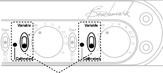
ADC1 Instruction Manual Page 15
Down Position
Rack Mounting
To enable rack mounting, the front panel of
the ADC1 has rack-mount holes that are
machined to conform to standard rack mount
dimensions. The width of the ADC1 panel is
exactly ½ that of a standard 19” panel. The
ADC1 is one rack unit high. Either ear of the
ADC1 can be mounted directly to a standard
19” rack. A machined junction block connects
the other ear to a ½ width blank panel,
another ADC1, a DAC1, or other ½ width
Benchmark products. When joined, the two
units form a single rigid 19” panel that can be
installed in any standard 19” rack.
ADC1 Instruction Manual Page 16
Using ADAT S/MUX
Proper S/MUX Identification is a
Must
S/MUX2 allows recording 4 channels at 88.2
or 96 kHz using a standard 8-channel 44.1 or
48 kHz ADAT recorder. S/MUX4 allows
recording 2 channels at 176.4 or 192 kHz
using a standard 8-channel 44.1 or 48 kHz
ADAT recorder. In either case it is important
to identify S/MUX recordings so that they can
be properly decoded upon playback. Failure to
properly decode an S/MUX recording will add
unwanted artifacts to the audio. The severity
of these artifacts is a function of the high-
frequency content of the original digital audio
signal, and may range from inaudible to very
objectionable. This variation in severity can
make it difficult to accurately spot a problem
just by listening to a portion of the recording.
An ADAT S/MUX2 recording will have pairs of
nearly identical tracks (1≈2, 3≈4, 5≈6, and
7≈8). Unfortunately this can be mistaken for
4 stereo pairs at half of the original sample
rate. There is no substitute for proper
labeling. This labeling should include the
sample rate of the recording.
An ADAT S/MUX4 recording is somewhat
easier to identify because it will have groups
of 4 channels that are nearly identical
(1≈2≈3≈4, and 5≈6≈7≈8). In error, S/MUX4
could be played at ¼ of its original sample
rate, and sound almost normal. S/MUX4 could
also be mistaken for S/MUX2 and could be
played at ½ of its original sample rate. Please
note that these changes in sample rate will
not alter the pitch of the audio but will
introduce errors. These errors may not be
discovered until it is too late.
S/MUX Must be Decoded Before
Digital Processing
No DSP process should be applied to an
S/MUX signal before it is decoded. S/MUX
must be decoded before it reaches the
internal processing in a DAW or a digital
console. Many such devices include S/MUX
decoders at their digital interfaces. These
decoders must be properly enabled for S/MUX
and must be disabled for standard ADAT
inputs.
Sample Rate is the Key that
Controls S/MUX
Most devices (including the ADC1)
automatically enable and disable S/MUX in
response to changes in sample rate.
Therefore it is essential that all S/MUX
equipped A/D converters, D/A converters,
digital consoles, digital audio workstations,
and digital processing devices be set to
identical sample rates. There is one exception
to this rule: A non-S/MUX ADAT recorder can
be connected to an S/MUX interface, but the
recorder must be set at ½ (S/MUX2) or ¼
(S/MUX4) of the actual sample rate.
S/MUX should not be used for
Sample Rate Conversion
If two devices are connected with an ADAT
S/MUX interface and the devices are set to
different sample rates, a crude form of
sample rate conversion will occur. For
example, if an A/D converter is set to 96 kHz,
and it feeds a digital console that is set to 48
kHz, the system will appear to down convert
from 96 kHz to 48 kHz. This would be a useful
feature if the digital filtering was correct. The
problem is that this ad-hoc sample rate
converter is lacking the low-pass filter that
prevents aliasing.

ADC1 Instruction Manual Page 17
UltraLock™ … What is It?
Accurate 24-bit audio conversion requires a
very low-jitter conversion clock. Jitter can
very easily turn a 24-bit converter into a 16-
bit converter (or worse). There is no point in
buying a 24-bit converter if clock jitter has
not been adequately addressed.
Jitter is present on every digital audio
interface. This type of jitter is known as
interface jitter and it is present even in the
most carefully designed audio systems.
Interface jitter accumulates as digital signals
travel down a cable and from one digital
device to the next. If we measure interface
jitter in a typical system we will find that it is
10 to 10,000 times higher than the level
required for accurate 24-bit conversion.
Fortunately, this interface jitter has absolutely
no effect on the audio unless it influences the
conversion clock in an analog-to-digital
converter (ADC) or in a analog-to-digital
converter (DAC).
Many converters use a single-stage Phase
Lock Loop (PLL) circuit to derive their
conversion clocks from AES/EBU, Word Clock,
or Super Clock reference signals. Single-stage
PLL circuits provide some jitter attenuation
above 5 kHz but none below 5 kHz.
Unfortunately, digital audio signals often have
their strongest jitter components at 2 kHz.
Consequently, these converters can achieve
their rated performance only when driven
from very low jitter sources and through very
short cables. It is highly unlikely that any
converter with a single-stage PLL can achieve
better than 16 bits of performance in a typical
installation. Specified performance may be
severely degraded in most installations.
Better converters usually use a two-stage PLL
circuit to filter out more of the interface jitter.
In theory, a two-stage PLL can remove
enough of the jitter to achieve accurate 24-bit
conversion (and some do). However, not all
two-stage PLL circuits are created equal.
Many two-stage PLLs do not remove enough
of the low-frequency jitter. In addition, two-
stage PLL circuits often require several
seconds to lock to an incoming signal. Finally,
a two-stage PLL may fail to lock when jitter is
too high, or when the reference sample
frequency has drifted.
UltraLock™ converters exceed the jitter
performance of two-stage PLL converters, and
are free from the slow-lock and no-lock
problems that can plague two-stage PLL
designs. UltraLock converters are 100%
immune to interface jitter under all operating
conditions. No jitter-induced artifacts can be
detected using an Audio Precision System 2
Cascade test set. Measurement limits include
detection of artifacts as low as –140 dBFS,
application of jitter amplitudes as high as
12.75 UI, and application of jitter over a
frequency range of 2 Hz to 200 kHz. Any
AES/EBU signal that can be decoded by the
AES/EBU receiver will be reproduced without
the addition of any measurable jitter artifacts.
The ADC1, DAC-104 and the ADC-104 employ
Benchmark’s new UltraLock technology to
eliminate all jitter-induced performance
problems. UltraLock isolates the conversion
clock from the digital audio interface clock.
Jitter on a DAC digital audio input, or an ADC
reference input can never have any
measurable effect on the conversion clock of
an UltraLock converter. In an UltraLock
converter, the conversion clock is never
phase-locked to a reference clock. Instead the
converter oversampling-ratio is varied with
extremely high precision to achieve the
proper phase relationship to the reference
clock. Interface jitter cannot degrade the
quality of the audio conversion. Specified
performance is consistent and repeatable in
any installation!
ADC1 Instruction Manual Page 18
How does conversion clock jitter
degrade converter performance?
Problem #1
Jitter phase modulates the audio signal. This
modulation creates sidebands (unwanted
tones) above and below every tone in the
audio signal. Worse yet, these sidebands are
often widely separated from the tones in the
original signal.
Jitter-induced sidebands are not musical in
nature because they are not harmonically
related to the original audio. Furthermore,
these sidebands are poorly masked (easy to
hear) because they can be widely separated
above and below the frequencies of the
original audio tones. In many ways, jitter
induced distortion resembles intermodulation
distortion (IMD). Like IMD, jitter induced
distortion is much more audible than
harmonic distortion, and more audible than
THD measurements would suggest.
Jitter creates new audio that is not
harmonically related to the original audio
signal. This new audio is unexpected and
unwanted. It can cause a loss of imaging, and
can add a low and mid frequency “muddiness”
that was not in the original audio.
Jitter induced sidebands can be measured
using an FFT analyzer.
Problem #2
Jitter can severely degrade the anti-alias
filters in an oversampling converter. This is a
little known but easily measurable effect.
Most audio converters operate at high
oversampling ratios. This allows the use of
high-performance digital anti-alias filters in
place of the relatively poor performing analog
anti-alias filters. In theory, digital anti-alias
filters can have extremely sharp cutoff
characteristics, and very few negative effects
on the in-band audio signal. Digital anti-alias
filters are usually designed to achieve at least
100 dB of stop-band attenuation. But, digital
filters are designed using the mathematical
assumption that the time interval between
samples is a constant. Unfortunately, sample
clock jitter in an ADC or DAC varies the
effective time interval between samples. This
variation alters the performance of these
carefully designed filters. Small amounts of
jitter can severely degrade stop-band
performance, and can render these filters
useless for preventing aliasing.
The obvious function of a digital anti-alias
filter is the removal of audio tones that are
too high in frequency to be represented at the
selected sample rate. The not-so-obvious
function is the removal of high-frequency
signals that originate inside the converter
box, or even originate inside the converter IC.
These high-frequency signals are a result of
crosstalk between digital and analog signals,
and may have high amplitudes in a poorly
designed system. Under ideal (low jitter)
conditions, a digital anti-alias filter may
remove most of this unwanted noise before it
can alias down into lower (audio) frequencies.
These crosstalk problems may not become
obvious until jitter is present.
Stop-band attenuation can be measured very
easily by sweeping a test tone between 24
kHz and at least 200 kHz while monitoring the
output of the converter.
Put UltraLock converters to the
test
We encourage our customers to perform the
above tests on UltraLock converters (or let
your ears be the judge). There will be
absolutely no change in performance as jitter
is added to any digital input on an UltraLock
converter.
Try the same tests on any converter using
conventional single or two-stage PLL circuits.
Tests should be performed with varying levels
of jitter and with varying jitter frequencies.
The results will be very enlightening. Jitter
related problems have audible (and
measurable) effects on ADC and DAC devices.
Practitioners of Digital Audio need to
understand these effects.
ADC1 Instruction Manual Page 19
Is it possible to eliminate all of
the effects of jitter in an entire
digital audio system?
Interface jitter will accumulate throughout
even the most carefully designed digital audio
system. Fortunately, interface jitter can only
degrade digital audio if it affects the sampling
circuit in an analog-to-digital or analog-to-
digital converter. Any attempt to cure jitter
outside of an ADC or DAC will prove
expensive and, at best, will only partially
reduce jitter-induced artifacts. Dedicated
clock signals (word clock, and super clock,
etc.) are often distributed to A/D converters
and D/A converters in an attempt to reduce
jitter. Again, these are only partial solutions
because jitter even accumulates in these
clock distribution systems. Furthermore, a
poor quality master clock generator can
degrade the performance of the entire system
(if converter performance is dependent upon
reference clock quality. Jitter free ADCs and
DACs are the only true insurance against the
ill effects of jitter. UltraLock converters are
jitter immune under all operating conditions
(they will never add audible jitter induced
artifacts to an audio signal).
What UltraLock converters cannot
do
UltraLock converters cannot undo damage
that has already been done. If an ADC with a
jitter problem was used to create a digital
audio signal, then there is nothing that can be
done to remove the damage. Jitter-induced
sidebands are extremely complex and cannot
be removed with any existing audio device. It
is therefore important to attack jitter at both
ends of the audio chain. The ADC1 is a great
start, as it will allow accurate assessment of
various A/D converters. It is impossible to
evaluate ADC performance without a good
DAC. The consistent performance delivered by
the ADC1 eliminates one major variable:
jitter.
ADC1 Instruction Manual Page 20
Performance
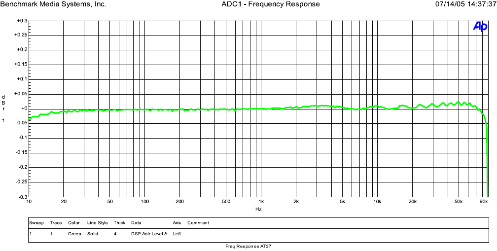
Frequency Response
The above graphs show the frequency response of the ADC1 when it is operating at a 192-kHz
sample rate. Note that the amplitude response is down by less than 0.05 dB at 10 Hz and 80 kHz.
The bass response extends well below the 10-Hz limitation of the measurement equipment, and
the high-frequency analog response extends well above the 96 kHz bandwidth of 192 kHz digital
audio.
ADC1 Instruction Manual Page 21
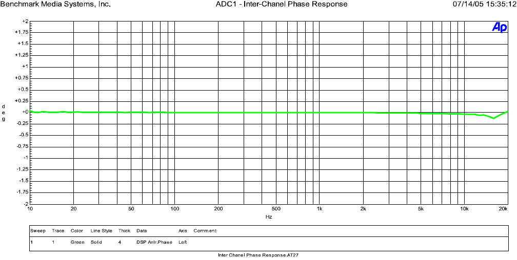
Inter-Channel Phase Response
This graph shows that the differential phase is significantly better than ± 0.25º from 10 Hz to 20
kHz.
ADC1 Instruction Manual Page 22
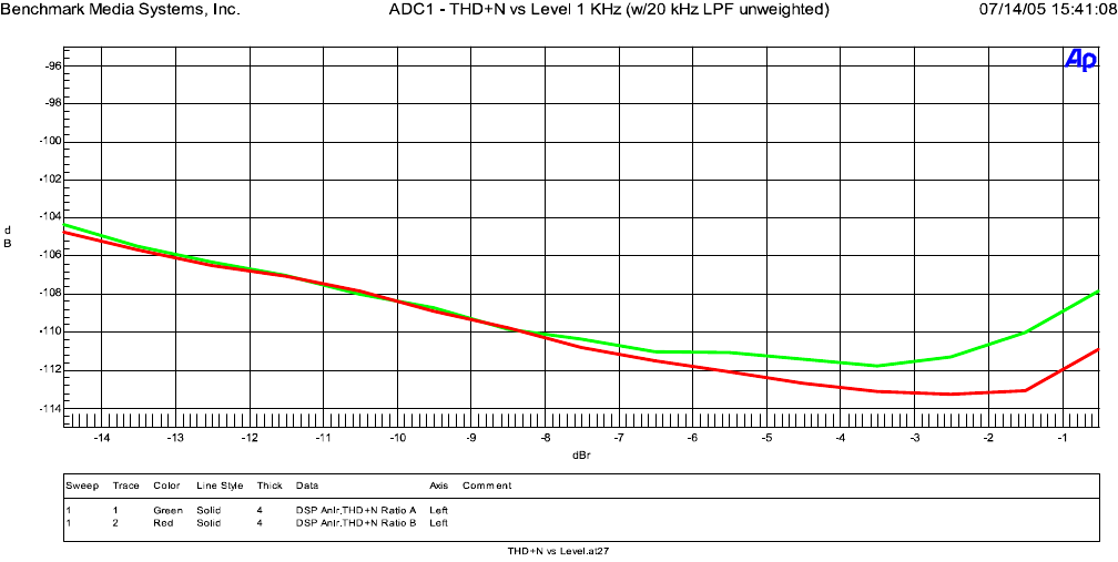
THD+N vs. Level, 1 KHz
w/20 kHz LPF unweighted
Below –4 dBFS, distortion is lower than the noise floor of the converter. Above –3 dBFS, distortion
reaches a maximum value of only –107 dBFS.
ADC1 Instruction Manual Page 23
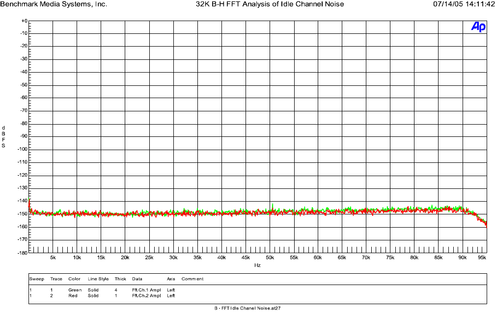
32K B-H FFT, Idle Channel Noise
The above graph demonstrates that the ADC1 is free from idle tones and clock crosstalk. The
highest spurious tone measures –128 dBFS and is AC line related hum. The highest non-line
related tone measures –135 dBFS.
ADC1 Instruction Manual Page 24
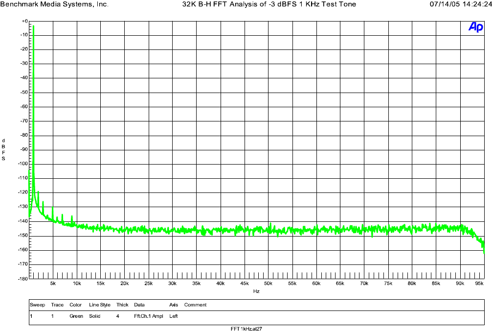
32K B-H FFT, -3 dBFS, 1 KHz
The above FFT plot shows that the ADC1 has very little harmonic distortion. Distortion is
exceptionally low and is dominated by 2nd harmonic distortion. Note the near absence of spurious
tones.
ADC1 Instruction Manual Page 25
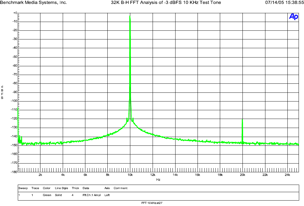
32K B-H FFT, -3 dBFS, 10 KHz
The above FFT plot shows that the ADC1 is free from jitter-induced sidebands. Any jitter present at
the conversion sampling circuit would produce sidebands equally spaced above and below the 10
kHz test tone. The tone at 20 kHz is due to second harmonic distortion, and measures almost 120
dB below full scale. Note the near absence of spurious tones.
ADC1 Instruction Manual Page 26
Specifications
Analog Audio Inputs
Number of Inputs (balanced) 2
Connector Gold-Pin Neutrik™ female XLR
Impedance 200 kΩ
Sensitivity -14dBu to +29 dBu (at 0 dBFS)
Clock Reference Input
Format Auto-detect AES/EBU, Word Clock,
and Super Clock (256x)
Impedance 75 Ω
Sensitivity 150 mV AES
200 mV Word Clock
750 mV Super Clock
Transformer Coupled Yes
DC Blocking Capacitors Yes
Transient and Over-Voltage Protection Yes
Jitter Attenuation Method Benchmark UltraLock™
Worldclock Reference Output
Impedance 75 Ω
Level 5 Vpp
2.5 Vpp into 75 Ω
Transformer Coupled No
DC Blocking Capacitors No
Transient and Over-Voltage Protection Yes
ADC1 Instruction Manual Page 27
Digital Audio Outputs
Number of Digital Outputs 1 XLR Main
1 TOSLINK Main
1 BNC Main
1 BNC Aux
Connectors Gold-Pin Neutrik™ male XLR
Number of Audio Channels 2
Main Output Word Length 24 bits
Main Output Sample Frequencies 44.1, 48, 88.2, 176.4, or 192 kHz
Aux Output Word Length 16 or 24 bits
Aux Output Sample Frequencies 44.1, 48, 88.2, 176.4, or 192 kHz at
24 bits
44.1 or 48 at 16 bits
Impedance 110 Ω XLR
75 Ω BNC
Level 4 Vpp into 100 Ω XLR
1 Vpp into 75 Ω BNC
Transformer Coupled Yes
DC Blocking Capacitors Yes
Transient and Over-Voltage Protection Yes
ADC1 Instruction Manual Page 28
Audio Performance
Fs = 44.1 to 192 kHz, 20 to 20 kHz BW, 1 kHz test tone, 0 dBFS = +24 dBu (unless noted)
SNR – A-Weighted, 0 dBFS = +8 to +29 dBu 121 dB
SNR – Unweighted, 0 dBFS = +8 to +29 dBu 119 dB
SNR – A-Weighted at max gain, 0 dBFS = -14 dBu 108 dB
THD+N, 1 kHz at –1 dBFS -102 dBFS, -101 dB, 0.00089%
THD+N, 1 kHz at –3 dBFS -107 dBFS, -104 dB, 0.00063%
THD+N, 20 to 20 kHz test tone at –3 dBFS -106 dBFS, -103 dB, 0.00071%
Frequency Response at Fs=192 kHz -3 dB, +0 dB, 2 Hz to 92 kHz
+/- 0.01 dB, 20 Hz to 20 kHz
-0.06 dB at 10 Hz
-0.01 dB at 20 Hz
-0.00 dB at 20 kHz
-0.18 dB at 88 kHz
-3 dB at 92 kHz
-100 dB at 108 kHz
Frequency Response at Fs=96 kHz -3 dB, +0 dB,1 Hz to 46 kHz
+/- 0.01 dB, 20 Hz to 20 kHz
-0.06 dB at 10 Hz
-0.01 dB at 20 Hz
-0.00 dB at 20 kHz
-0.10 dB at 44 kHz
-3 dB at 46 kHz
-108 dB at 54 kHz
Frequency Response at Fs=48 kHz 3 dB, +0 dB, 1 Hz to 23 kHz
+/- 0.01 dB, 20 Hz to 20 kHz
-0.06 dB at 10 Hz
-0.01 dB at 20 Hz
-0.00 dB at 20 kHz
-0.10 dB at 22 kHz
-3 dB at 23 kHz,
-110 dB at 27 kHz
Passband Ripple +/- 0.008 dB
Crosstalk -105 dB at 20 kHz
-130 dB at 1 kHz
-200 dB at 20 Hz
ADC1 Instruction Manual Page 29
Jitter Tolerance (With no Measurable Change in
Performance)
>12.75 UI sine, 100 Hz to 10 kHz
> 3.5 UI sine at 20 kHz
> 1.2 UI sine at 40 kHz
> 0.4 UI sine at 80 kHz
> 0.29 UI sine at 90 kHz
> 0.25 UI sine above 160 kHz
Maximum Amplitude of Jitter Induced Sidebands < -134 dB (measurement limit) (10
kHz 0 dBFS test tone, 12.75 UI
sinusoidal jitter at 1 kHz)
Maximum Amplitude of Spurious Tones with 0 dBFS test
signal
-130 dBFS
Maximum Amplitude of Idle Tones -145 dBFS
Maximum Amplitude of AC line related Hum & Noise -130 dBFS
Interchannel Differential Phase (Stereo Pair) +/- 0.5 degrees at 20 kHz
Interchannel Differential Phase (Between ADC1 Units) +/- 0.5 degrees at 20 kHz
Maximum Lock Time after Fs change < 1 s for frequency lock
< 5 s for phase lock
Mute on Sample Rate Change Yes
Mute on Loss of External Clock No
Mute on Lock Error No
Mute on Receive Error No
Soft Mute Ramp Up/Down Time 10 ms
Group Delay (Latency)
Delay (Analog Input to Digital Output) 1.20 ms at 44.1 kHz
1.09 ms at 48 kHz
0.75 ms at 88.2 kHz
0.67 ms at 96 kHz
0.63 ms at 176.4 kHz
0.59 ms at 192 kHz
LED Status Indicators
LED Location Front Panel
Mode Indicators 9 green
Meter 14 green, 2 yellow, 2 red
ADC1 Instruction Manual Page 30
AC Power Requirements
Input Operating Voltage Range (VAC RMS) 110 V setting – 95 V min, 140 V max
220 V setting – 190 V min, 285 V
max
Frequency 50-60 Hz
Power 16 Watts Idle
16 Watts Typical Program
20 Watts Maximum
Fuses 5 x 20 mm (2 required)
110 V setting – 0.5 A 250 V Slo-Blo®
Type
220 V setting – 0.5 A 250 V Slo-Blo®
Type
Dimensions
Form Factor ½ Rack Wide, 1 RU High
Depth behind front panel 8.5” (216 mm)
Overall depth including connectors but without power
cord or BNC-to-RCA adapter
9.33” (237 mm)
Width 9.5” (249 mm)
Height 1.725” (44.5 mm)
Weight
ADC1 only 3.6 lb.
ADC1 with power cord, 3 BNC-to-RCA adapters, extra
fuses, and manual
4.9 lb.
Rack mount kit (blank panel, junction block, and rack-
mount screws)
0.32 lb.
Shipping weight 7 lb.
ADC1 Instruction Manual Page 31

ADC1 Instruction Manual Page 32
Warranty Information
Benchmark 1 Year Warranty
The Benchmark 1 Year Warranty
Benchmark Media Systems, Inc. warrants its products to be free from defects in material and
workmanship under normal use and service for a period of one (1) year from the date of
delivery.
This warranty extends only to the original purchaser. This warranty does not apply to fuses,
lamps, batteries, or any products or parts that have been subjected to misuse, neglect,
accident, modification, or abnormal operating conditions.
In the event of failure of a product under this warranty, Benchmark Media Systems, Inc. will
repair, at no charge, the product returned to its factory. Benchmark Media Systems, Inc. may,
at its option, replace the product in lieu of repair. If the failure has been caused by misuse,
neglect, accident, or, abnormal operating conditions, repairs will be billed at the normal shop
rate. In such cases, an estimate will be submitting before work is started, if requested by the
customer.
Attempts to deliberately deface, mutilate, or remove the product's label will render this
warranty void. Any ADC1 with a serial number greater than 00261 returned from the European
Union for warranty repair must have the required RoHS logo on the product label; otherwise,
repairs will be billed at the normal shop rate. Benchmark will not honor warranties for any
products disingenuously purchased on the US or Canadian markets for sale outside the US or
Canada.
The foregoing warranty is in lieu of all other warranties, expressed or implied, including but not
limited to any implied warranty of merchantability, fitness or adequacy for any particular
purpose or use. Benchmark Media Systems, Inc. shall not be liable for any special, incidental,
or consequential damages, and reserves the right to charge this information without notice.
This limited warranty gives the consumer-owner specific legal rights, and there may also be
other rights that vary form state to state.

ADC1 Instruction Manual Page 33
Benchmark Extended Warranty
The Benchmark Extended 5* Year Warranty
Benchmark Media Systems, Inc. optionally extends the standard one (1) year warranty to a
period of five (5)* years from the date of delivery.
*For the extended warranty to become effective, the original purchaser must register the
product at the time of purchase either by way of the prepaid registration card or through the
product registration section of the Benchmark Media Systems, Inc. website. This optional
warranty applies only to products purchased within the US and Canada and is extended only to
the original purchaser.
Attempts to deliberately deface, mutilate, or remove the product's label will render this
warranty void. Benchmark will not honor warranties for any products disingenuously purchased
on the US or Canadian markets for export. The terms of the extended warranty are subject to
change without notice. For products purchased outside the US and Canada, please refer to the
Extended Two (2)** Year International Warranty.
The Benchmark’s Extended 2** Year
International Warranty
Benchmark Media Systems, Inc. optionally extends the standard one (1) year warranty to a
period of two (2)** years from the date of delivery.
**For the extended warranty to become effective, the original purchaser must register the
product at the time of purchase either by way of the prepaid registration card or through the
product registration section of the Benchmark Media Systems, Inc. website. This optional
warranty applies only to products purchased outside the US and Canada and is extended only
to the original purchaser.
Attempts to deliberately deface, mutilate, or remove the product's label will render this
warranty void. Benchmark will not honor warranties for any products disingenuously purchased
on the US or Canadian markets for export. The terms of the extended warranty are subject to
h ith t ti F d t h d i ithi th US d C d l f t th
Notes on Warranty Repairs
An RMA (return merchandise authorization) number, issued by our Customer Service
Department, is required when sending products for repair.
They must be shipped to Benchmark Media Systems prepaid and preferably in their original
shipping carton with the RMA number clearly visible on the exterior of the packaging. A letter
should be included
g
ivin
g
full details of the difficult
y
.

ADC1 Instruction Manual Page 34
Copyright © 2005 Benchmark Media Systems, Inc.
All rights reserved.
Benchmark Media Systems, Inc.
5925 Court Street Road
Syracuse, NY 13206-1707
USA
+1-315 437-6300, FAX +1-315-437-8119
http://www.benchmarkmedia.com
