ADC NXD 75210 User Manual To The 4a1bb5e3 Fbdb 4eff 9c71 F976df3bde1c
User Manual: ADC NXD to the manual
Open the PDF directly: View PDF ![]() .
.
Page Count: 84
- Front Cover
- Copyright, Revision History, Trademarks
- Table of Contents
- About This Manual
- Related Publications
- Admonishments
- General Safety Precautions
- Safe Working Distances
- Standards Certification
- List of Acronyms and Abbreviations
- 1 Product Description
- 1.1 General Description
- 1.2 System Function
- 1.3 High-Level View
- 1.4 User Interface
- 1.5 Dimensions and Specifications
- 1.6 RAN Cabinet
- 1.7 RAN Chassis and Electronic Modules
- 1.7.1 cPCI Power Supply Modules
- 1.7.2 Central Processing Unit (CPU) Module
- 1.7.3 System Interface (STF2) Module
- 1.7.4 Synchronous Interface (SIF) Module
- 1.7.5 Small Form-Factor Pluggable (SFP) Optical Transceiver
- 1.7.6 RAN Down Converter (RDC or RDC2) Module
- 1.7.7 RAN Up Converter (RUC2.X or RUC3) Module
- 1.7.8 Fan Access Panel
- 1.7.9 800 MHz Multicoupler (C/MCPLR)
- 1.7.10 1900 MHz Multicoupler (P/MCPLR)
- 1.8 Rectifier Shelf
- 1.9 Power Amplifier Assembly
- 1.10 Multiplexer System
- 1.11 Circuit Breaker Panel
- 1.12 Backup Batteries
- 1.13 Antenna
- 2 Standard Installation Procedures
- 3 Installing an Extension RAN (Pole Mount)
- 4 Non-Standard Installation Procedures
- 4.1 Installing an Electronic Module
- 4.1.1 Installing a Central Processing Unit (CPU) Module
- 4.1.2 Installing a Systems Interface (STF2) Module
- 4.1.3 Installing a Synchronous Interface (SIF) Module
- 4.1.4 Installing a Small Form-Factor Optical Transceiver (SFP)
- 4.1.5 Installing a RAN Down Converter (RDC or RDC2) Module
- 4.1.6 Installing a RAN Up Converter (RUC2.X or RUC3) Module
- 4.2 Installing cPCI Chassis Air Baffles
- 4.3 Installing a Rectifier Module
- 4.4 Installing a Compact PCI Power Supply (cPCI P/S) Module
- 4.5 Installing a Power Amplifier Assembly
- 4.1 Installing an Electronic Module
- 5 Maintenance Procedures
- 6 Customer Information and Assistance
ADCP-75-210
Issue 1
March 2007
1356011 Rev A
Digivance® NXD
Radio Access Node (RAN)
Installation and Maintenance Manual
21227-A

ADCP-75-210 • Issue 1 • March 2007 • Preface
Page ii
COPYRIGHT
© 2006, ADC Telecommunications, Inc.
All Rights Reserved
Printed in the U.S.A.
REVISION HISTORY
TRADEMARK INFORMATION
Digivance is a registered trademark of ADC Telecommunications, Inc.
ADC is a trademark of ADC Telecommunications, Inc.
DISCLAIMER OF LIABILITY
Contents herein are current as of the date of publication. ADC reserves the right to change the contents without prior notice. In no
event shall ADC be liable for any damages resulting from loss of data, loss of use, or loss of profits and ADC further
disclaims any and all liability for indirect, incidental, special, consequential or other similar damages. This disclaimer of
liability applies to all products, publications and services during and after the warranty period.
This publication may be verified at any time by contacting ADC’s Technical Assistance Center at 1-800-366-3891, extension 73475
(in U.S.A. or Canada) or 952-917-3475 (outside U.S.A. and Canada), or by e-mail to connectivity_tac@adc.com.
ISSUE DATE REASON FOR CHANGE
1 02/2007 Original.
ADC Telecommunications, Inc.
P.O. Box 1101, Minneapolis, Minnesota 55440-1101
In U.S.A. and Canada: 1-800-366-3891
Outside U.S.A. and Canada: (952) 938-8080
Fax: (952) 917-1717

ADCP-75-210 • Issue 1 • March 2007 • Preface
Page iii
© 2007, ADC Telecommunications, Inc.
TABLE OF CONTENTS
Content Page
About This Manual . . . . . . . . . . . . . . . . . . . . . . . . . . . . . . . . . . . . . . . . . . . . . . . . . . . . . . . . . . . . . . . . . . . . . . . . . . vii
RELATED PUBLICATIONS . . . . . . . . . . . . . . . . . . . . . . . . . . . . . . . . . . . . . . . . . . . . . . . . . . . . . . . . . . . . . . . . . . . . . . vii
AdmonishmentS . . . . . . . . . . . . . . . . . . . . . . . . . . . . . . . . . . . . . . . . . . . . . . . . . . . . . . . . . . . . . . . . . . . . . . . . . . . .viii
General Safety Precautions . . . . . . . . . . . . . . . . . . . . . . . . . . . . . . . . . . . . . . . . . . . . . . . . . . . . . . . . . . . . . . . . . . . .viii
Safe Working Distances . . . . . . . . . . . . . . . . . . . . . . . . . . . . . . . . . . . . . . . . . . . . . . . . . . . . . . . . . . . . . . . . . . . . . . . .ix
STANDARDS CERTIFICATION . . . . . . . . . . . . . . . . . . . . . . . . . . . . . . . . . . . . . . . . . . . . . . . . . . . . . . . . . . . . . . . . . . . .ix
LIST OF ACRONYMS AND ABBREVIATIONS . . . . . . . . . . . . . . . . . . . . . . . . . . . . . . . . . . . . . . . . . . . . . . . . . . . . . . . . . . . x
1 PRODUCT DESCRIPTION . . . . . . . . . . . . . . . . . . . . . . . . . . . . . . . . . . . . . . . . . . . . . . . . . . . . . . . . . . . . . . . . . . 1
1.1 General Description . . . . . . . . . . . . . . . . . . . . . . . . . . . . . . . . . . . . . . . . . . . . . . . . . . . . . . . . . . . . . . . . 1
1.2 System Function . . . . . . . . . . . . . . . . . . . . . . . . . . . . . . . . . . . . . . . . . . . . . . . . . . . . . . . . . . . . . . . . . . 2
1.3 High-Level View . . . . . . . . . . . . . . . . . . . . . . . . . . . . . . . . . . . . . . . . . . . . . . . . . . . . . . . . . . . . . . . . . . 3
1.4 User Interface . . . . . . . . . . . . . . . . . . . . . . . . . . . . . . . . . . . . . . . . . . . . . . . . . . . . . . . . . . . . . . . . . . . . 4
1.5 Dimensions and Specifications . . . . . . . . . . . . . . . . . . . . . . . . . . . . . . . . . . . . . . . . . . . . . . . . . . . . . . . . 6
1.6 RAN Cabinet . . . . . . . . . . . . . . . . . . . . . . . . . . . . . . . . . . . . . . . . . . . . . . . . . . . . . . . . . . . . . . . . . . . . . 8
1.6.1 Mounting . . . . . . . . . . . . . . . . . . . . . . . . . . . . . . . . . . . . . . . . . . . . . . . . . . . . . . . . . . . . . . . . 9
1.6.2 Fiber Optic Cable Entry. . . . . . . . . . . . . . . . . . . . . . . . . . . . . . . . . . . . . . . . . . . . . . . . . . . . . . . 9
1.6.3 Antenna Cable Connections . . . . . . . . . . . . . . . . . . . . . . . . . . . . . . . . . . . . . . . . . . . . . . . . . . . 9
1.6.4 AC Power Wiring Entry and Grounding . . . . . . . . . . . . . . . . . . . . . . . . . . . . . . . . . . . . . . . . . . . . 9
1.6.5 Ventilation . . . . . . . . . . . . . . . . . . . . . . . . . . . . . . . . . . . . . . . . . . . . . . . . . . . . . . . . . . . . . . . 9
1.7 RAN Chassis and Electronic Modules . . . . . . . . . . . . . . . . . . . . . . . . . . . . . . . . . . . . . . . . . . . . . . . . . . . 10
1.7.1 cPCI Power Supply Modules . . . . . . . . . . . . . . . . . . . . . . . . . . . . . . . . . . . . . . . . . . . . . . . . . . 12
1.7.2 Central Processing Unit (CPU) Module . . . . . . . . . . . . . . . . . . . . . . . . . . . . . . . . . . . . . . . . . . . 13
1.7.3 System Interface (STF2) Module . . . . . . . . . . . . . . . . . . . . . . . . . . . . . . . . . . . . . . . . . . . . . . . 14
1.7.4 Synchronous Interface (SIF) Module . . . . . . . . . . . . . . . . . . . . . . . . . . . . . . . . . . . . . . . . . . . . 15
1.7.5 Small Form-Factor Pluggable (SFP) Optical Transceiver. . . . . . . . . . . . . . . . . . . . . . . . . . . . . . . 17
1.7.6 RAN Down Converter (RDC or RDC2) Module. . . . . . . . . . . . . . . . . . . . . . . . . . . . . . . . . . . . . . . 17
1.7.7 RAN Up Converter (RUC2.X or RUC3) Module . . . . . . . . . . . . . . . . . . . . . . . . . . . . . . . . . . . . . . 19
1.7.8 Fan Access Panel . . . . . . . . . . . . . . . . . . . . . . . . . . . . . . . . . . . . . . . . . . . . . . . . . . . . . . . . . 20
1.7.9 800 MHz Multicoupler (C/MCPLR) . . . . . . . . . . . . . . . . . . . . . . . . . . . . . . . . . . . . . . . . . . . . . . 20
1.7.10 1900 MHz Multicoupler (P/MCPLR) . . . . . . . . . . . . . . . . . . . . . . . . . . . . . . . . . . . . . . . . . . . . . 22
1.8 Rectifier Shelf. . . . . . . . . . . . . . . . . . . . . . . . . . . . . . . . . . . . . . . . . . . . . . . . . . . . . . . . . . . . . . . . . . . 23
1.8.1 Rectifier Module . . . . . . . . . . . . . . . . . . . . . . . . . . . . . . . . . . . . . . . . . . . . . . . . . . . . . . . . . . 23
1.8.2 Low Voltage Disconnect (LVD) Unit . . . . . . . . . . . . . . . . . . . . . . . . . . . . . . . . . . . . . . . . . . . . . 24
1.9 Power Amplifier Assembly . . . . . . . . . . . . . . . . . . . . . . . . . . . . . . . . . . . . . . . . . . . . . . . . . . . . . . . . . . 25
1.10 Multiplexer System . . . . . . . . . . . . . . . . . . . . . . . . . . . . . . . . . . . . . . . . . . . . . . . . . . . . . . . . . . . . . . . 26
1.11 Circuit Breaker Panel . . . . . . . . . . . . . . . . . . . . . . . . . . . . . . . . . . . . . . . . . . . . . . . . . . . . . . . . . . . . . . 28
1.12 Backup Batteries . . . . . . . . . . . . . . . . . . . . . . . . . . . . . . . . . . . . . . . . . . . . . . . . . . . . . . . . . . . . . . . . . 29
1.13 Antenna . . . . . . . . . . . . . . . . . . . . . . . . . . . . . . . . . . . . . . . . . . . . . . . . . . . . . . . . . . . . . . . . . . . . . . . 29
2 STANDARD INSTALLATION PROCEDURES . . . . . . . . . . . . . . . . . . . . . . . . . . . . . . . . . . . . . . . . . . . . . . . . . . . . . 30
2.1 Installation Overview . . . . . . . . . . . . . . . . . . . . . . . . . . . . . . . . . . . . . . . . . . . . . . . . . . . . . . . . . . . . . . 30
2.2 Unpacking and Inspection. . . . . . . . . . . . . . . . . . . . . . . . . . . . . . . . . . . . . . . . . . . . . . . . . . . . . . . . . . . 31

ADCP-75-210 • Issue 1 • March 2007 • Preface
Page iv
© 2007, ADC Telecommunications, Inc.
TABLE OF CONTENTS
Content Page
2.3 Required Materials and Tools . . . . . . . . . . . . . . . . . . . . . . . . . . . . . . . . . . . . . . . . . . . . . . . . . . . . . . . . 31
2.4 Site Preparation . . . . . . . . . . . . . . . . . . . . . . . . . . . . . . . . . . . . . . . . . . . . . . . . . . . . . . . . . . . . . . . . . 32
2.4.1 Space Requirements . . . . . . . . . . . . . . . . . . . . . . . . . . . . . . . . . . . . . . . . . . . . . . . . . . . . . . . 32
2.4.2 Power Requirements . . . . . . . . . . . . . . . . . . . . . . . . . . . . . . . . . . . . . . . . . . . . . . . . . . . . . . . 33
2.4.3 Antenna Requirement . . . . . . . . . . . . . . . . . . . . . . . . . . . . . . . . . . . . . . . . . . . . . . . . . . . . . . 33
2.4.4 RF Cable Requirements . . . . . . . . . . . . . . . . . . . . . . . . . . . . . . . . . . . . . . . . . . . . . . . . . . . . . 33
2.4.5 Fiber Requirements . . . . . . . . . . . . . . . . . . . . . . . . . . . . . . . . . . . . . . . . . . . . . . . . . . . . . . . . 34
2.5 Installing a RAN Cabinet on a Wooden Utility Pole . . . . . . . . . . . . . . . . . . . . . . . . . . . . . . . . . . . . . . . . . . 34
2.5.1 Site Requirements Unique to Pole Mounting Locations. . . . . . . . . . . . . . . . . . . . . . . . . . . . . . . . 34
2.5.2 Pole Loading Analysis . . . . . . . . . . . . . . . . . . . . . . . . . . . . . . . . . . . . . . . . . . . . . . . . . . . . . . 35
2.5.3 Installing the Cabinet Mounting Bracket . . . . . . . . . . . . . . . . . . . . . . . . . . . . . . . . . . . . . . . . . . 36
2.5.4 Mounting the RAN Cabinet on the Bracket . . . . . . . . . . . . . . . . . . . . . . . . . . . . . . . . . . . . . . . . . 38
2.5.5 Installing the Rain Shields . . . . . . . . . . . . . . . . . . . . . . . . . . . . . . . . . . . . . . . . . . . . . . . . . . . 38
2.6 Installing a RAN Cabinet on a Concrete Pad . . . . . . . . . . . . . . . . . . . . . . . . . . . . . . . . . . . . . . . . . . . . . . 39
2.6.1 Pouring a Concrete Pad . . . . . . . . . . . . . . . . . . . . . . . . . . . . . . . . . . . . . . . . . . . . . . . . . . . . . 40
2.6.2 Mounting the Cabinet on a Concrete Pad . . . . . . . . . . . . . . . . . . . . . . . . . . . . . . . . . . . . . . . . . 40
2.6.3 Installing the Pedestal Enclosure. . . . . . . . . . . . . . . . . . . . . . . . . . . . . . . . . . . . . . . . . . . . . . . 42
2.7 Other Standard Installation Procedures . . . . . . . . . . . . . . . . . . . . . . . . . . . . . . . . . . . . . . . . . . . . . . . . . 43
2.7.1 Installing a Solar Shield. . . . . . . . . . . . . . . . . . . . . . . . . . . . . . . . . . . . . . . . . . . . . . . . . . . . . 43
2.7.2 Installing a Ground Wire . . . . . . . . . . . . . . . . . . . . . . . . . . . . . . . . . . . . . . . . . . . . . . . . . . . . 44
2.7.3 Installing RF Cabling . . . . . . . . . . . . . . . . . . . . . . . . . . . . . . . . . . . . . . . . . . . . . . . . . . . . . . . 45
2.7.3.1 Weatherproofing RF Cables . . . . . . . . . . . . . . . . . . . . . . . . . . . . . . . . . . . . . . . . . . . . . . . . 46
2.7.3.2 Routing and Securing RF Cables . . . . . . . . . . . . . . . . . . . . . . . . . . . . . . . . . . . . . . . . . . . . 46
2.7.4 Installing Pre-Connectorized Indoor/Outdoor Fiber Optic Cable . . . . . . . . . . . . . . . . . . . . . . . . . . 47
2.7.5 Installing AC Power . . . . . . . . . . . . . . . . . . . . . . . . . . . . . . . . . . . . . . . . . . . . . . . . . . . . . . . . 49
2.7.6 Installing Backup Batteries (Extended or Glitch) . . . . . . . . . . . . . . . . . . . . . . . . . . . . . . . . . . . . 50
2.7.6.1 Battery Safety Rules . . . . . . . . . . . . . . . . . . . . . . . . . . . . . . . . . . . . . . . . . . . . . . . . . . . . . 50
2.7.6.2 Battery Installation . . . . . . . . . . . . . . . . . . . . . . . . . . . . . . . . . . . . . . . . . . . . . . . . . . . . . . 51
3 INSTALLING AN EXTENSION RAN (POLE MOUNT) . . . . . . . . . . . . . . . . . . . . . . . . . . . . . . . . . . . . . . . . . . . . . . . . 54
4 NON-STANDARD INSTALLATION PROCEDURES . . . . . . . . . . . . . . . . . . . . . . . . . . . . . . . . . . . . . . . . . . . . . . . . . . 57
4.1 Installing an Electronic Module . . . . . . . . . . . . . . . . . . . . . . . . . . . . . . . . . . . . . . . . . . . . . . . . . . . . . . . 57
4.1.1 Installing a Central Processing Unit (CPU) Module. . . . . . . . . . . . . . . . . . . . . . . . . . . . . . . . . . . 60
4.1.2 Installing a Systems Interface (STF2) Module . . . . . . . . . . . . . . . . . . . . . . . . . . . . . . . . . . . . . . 61
4.1.3 Installing a Synchronous Interface (SIF) Module . . . . . . . . . . . . . . . . . . . . . . . . . . . . . . . . . . . . 62
4.1.4 Installing a Small Form-Factor Optical Transceiver (SFP) . . . . . . . . . . . . . . . . . . . . . . . . . . . . . . 63
4.1.5 Installing a RAN Down Converter (RDC or RDC2) Module . . . . . . . . . . . . . . . . . . . . . . . . . . . . . . 63
4.1.6 Installing a RAN Up Converter (RUC2.X or RUC3) Module . . . . . . . . . . . . . . . . . . . . . . . . . . . . . . 64
4.2 Installing cPCI Chassis Air Baffles . . . . . . . . . . . . . . . . . . . . . . . . . . . . . . . . . . . . . . . . . . . . . . . . . . . . . 66
4.3 Installing a Rectifier Module. . . . . . . . . . . . . . . . . . . . . . . . . . . . . . . . . . . . . . . . . . . . . . . . . . . . . . . . . 66
4.4 Installing a Compact PCI Power Supply (cPCI P/S) Module . . . . . . . . . . . . . . . . . . . . . . . . . . . . . . . . . . . . 68
4.5 Installing a Power Amplifier Assembly . . . . . . . . . . . . . . . . . . . . . . . . . . . . . . . . . . . . . . . . . . . . . . . . . . 68

ADCP-75-210 • Issue 1 • March 2007 • Preface
Page v
© 2007, ADC Telecommunications, Inc.
TABLE OF CONTENTS
Content Page
5 MAINTENANCE PROCEDURES . . . . . . . . . . . . . . . . . . . . . . . . . . . . . . . . . . . . . . . . . . . . . . . . . . . . . . . . . . . . . . 70
5.1 cPCI Fan Replacement Procedure . . . . . . . . . . . . . . . . . . . . . . . . . . . . . . . . . . . . . . . . . . . . . . . . . . . . . 70
5.2 Cleaning or Replacing an Air Inlet Filter . . . . . . . . . . . . . . . . . . . . . . . . . . . . . . . . . . . . . . . . . . . . . . . . . 70
6 CUSTOMER INFORMATION AND ASSISTANCE . . . . . . . . . . . . . . . . . . . . . . . . . . . . . . . . . . . . . . . . . . . . . . . . . . . 72

ADCP-75-210 • Issue 1 • March 2007 • Preface
Page vi
© 2007, ADC Telecommunications, Inc.
TABLE OF CONTENTS
Content Page

ADCP-75-210 • Issue 1 • March 2007 • Preface
Page vii
© 2007, ADC Telecommunications, Inc.
ABOUT THIS MANUAL
This manual provides the following information:
• An overview of the Digivance NXD system;
• A description of the NXD system Radio Access Node (RAN);
• Installation procedures for the RAN;
• Maintenance procedures for the RAN;
• Product support information.
Procedures for installing and operating other NXD system components including the system
“Hub” and the EMS software that provides a user interface for the system, are available in other
ADC publications, listed under “Related Publications” below, and at appropriate points within
this manual.
RELATED PUBLICATIONS
Listed below are related manuals, their content, and their publication numbers. Copies of these
publications can be ordered by contacting the Technical Assistance Center at 1-800-366-3891,
extension 73476 (in U.S.A. or Canada) or 952-917-3476 (outside U.S.A. and Canada). All ADC
technical publications are available for downloading from the ADC web site at www.adc.com.
Digivance CXD/NXD Hub Installation and Maintenance Manual 75-193
Provides instructions for installing and operating the NXD system Hub.
Digivance CXD/NXD SNMP Agent and Fault Isolation User Guide 75-195
Describes how to troubleshoot the system using the parameters accessed
through the NXD system SNMP agents.
Digivance CXD/NXD Element Management System User Manual 75-199
Provides instructions for installing and using the Element Management System
(EMS) software for the NXD system.
Digivance NXD Multi-Band Distributed Antenna System Operation Manual 75-209
Provides instructions for turning up and operating NXD equipment.
2 in. O.D. Quad Cellular/PCS Omni-Directional Antenna Installation Manual 75-215
Provides instructions for installing an RF antenna for the NXD system
9 in. O.D. Quad Cellular/PCS Omni-Directional Antenna Installation Manual 75-221
Provides instructions for installing an RF antenna for the NXD system
Title/Description ADCP Number

ADCP-75-210 • Issue 1 • March 2007 • Preface
Page viii
© 2007, ADC Telecommunications, Inc.
ADMONISHMENTS
Important safety admonishments are used throughout this manual to warn of possible hazards to
persons or equipment. An admonishment identifies a possible hazard and then explains what
may happen if the hazard is not avoided. The admonishments — in the form of Dangers,
Warnings, and Cautions — must be followed at all times.
These warnings are flagged by use of the triangular alert icon (seen below), and are listed in
descending order of severity of injury or damage and likelihood of occurrence.
GENERAL SAFETY PRECAUTIONS
-
Danger: Danger is used to indicate the presence of a hazard that will cause severe personal
injury, death, or substantial property damage if the hazard is not avoided.
Warning: Warning is used to indicate the presence of a hazard that can cause severe personal
injury, death, or substantial property damage if the hazard is not avoided.
Caution: Caution is used to indicate the presence of a hazard that will or can cause minor
personal injury or property damage if the hazard is not avoided.
Warning: Wet conditions increase the potential for receiving an electrical shock when
installing or using electrically-powered equipment. To prevent electrical shock, never install or
use electrical equipment in a wet location or during a lightning storm.
Danger: This equipment uses a Class 1 Laser according to FDA/CDRH rules. Laser radiation
can seriously damage the retina of the eye. Do not look into the ends of any optical fiber. Do not
look directly into the optical transceiver of any digital unit or exposure to laser radiation may
result. An optical power meter should be used to verify active fibers. A protective cap or hood
MUST be immediately placed over any radiating transceiver or optical fiber connector to avoid
the potential of dangerous amounts of radiation exposure. This practice also prevents dirt
particles from entering the adapter or connector.
Caution: This system is a RF Transmitter and continuously emits RF energy. Maintain 3 foot
(91.4 cm) minimum clearance from the antenna while the system is operating. Wherever
possible, shut down the RAN before servicing the antenna.
Caution: Always allow sufficient fiber length to permit routing of patch cords and pigtails
without severe bends. Fiber optic patch cords or pigtails may be permanently damaged if bent
or curved to a radius of less than 2 inches (5.1 cm).
Caution: Exterior surfaces of the RAN may be hot. Use caution during servicing.

ADCP-75-210 • Issue 1 • March 2007 • Preface
Page ix
© 2007, ADC Telecommunications, Inc.
SAFE WORKING DISTANCES
The Digivance NXD antenna, which is mounted on top of a pole, radiates radio frequency
energy.
For the occupational worker, safe working distance from the antenna depends on the workers
location with respect to the antenna and the number of wireless service providers being serviced
by that antenna.
Emission limits are from OET Bulletin 65 Edition 97-01, Table 1 A.
STANDARDS CERTIFICATION
FCC: The Digivance NXD complies with the applicable sections of Title 47 CFR Part 15, 22,
24 and 90.
The Digivance NXD Hub has been tested and found to comply with the limits for a Class A dig-
ital device, pursuant to Part 15 of the FCC rules. These limits are designed to provide reasonable
protection against harmful interference when the equipment is operated in a commercial envi-
ronment. This equipment generates, uses, and can radiate radio frequency energy and, if not
installed and used in accordance with the instruction manual, may cause harmful interference to
radio communications.
Changes and modifications not expressly approved by the manufacturer or registrant of this
equipment can void your authority to operate this equipment under Federal Communications
Commissions rules.
In order to maintain compliance with FCC regulations, shielded cables must be used with this
equipment. Operation with non-approved equipment or unshielded cables is likely to result in
interference to radio & television reception.
ETL: This equipment complies with ANSI/UL 60950-1 Information Technology Equipment.
This equipment provides the degree of protection specified by IP24 as defined in IEC
Publication 529. Ethernet signals are not for outside plant use.
FDA/CDRH: This equipment uses a Class 1 LASER according to FDA/CDRH Rules. This
product conforms to all applicable standards of 21 CFR Part 1040.
IC: This equipment complies with the applicable sections of RSS-131. The term “IC:” before
the radio certification number only signifies that Industry Canada Technical Specifications
were met.
Wind Loading: The NXD RAN is able to withstand wind loads up to 150 mph.

ADCP-75-210 • Issue 1 • March 2007 • Preface
Page x
© 2007, ADC Telecommunications, Inc.
LIST OF ACRONYMS AND ABBREVIATIONS
The acronyms and abbreviations used in this manual are detailed in the following list:
AC Alternating Current
ANT Multiband Antenna
BIM Base Station Interface Module
BTS Base Transceiver Station
CCentigrade
CDRH Center for Devices and Radiological Health
C/MCPLR Cellular SMR Multicoupler
CM Centimeter
cPCI CompactPCI
CPU Central Processing Unit
CXD Compact RAN
DAS Distributed Antenna System
dB(FS) decibals (Full Scale – digital reading)
DC Direct Current
Div Diversity
EMS Element Management System
ESD Electrostatic Discharge
FFahrenheit
FDA U.S. Food and Drug Administration
FCC U.S. Federal Communications Commission
GPS Global Positioning System
IC Industry Canada
IN Inch
IP Internet Protocol
KG Kilogram
LED Light Emitting Diode
LSE Location Services Equipment
LVD Low Voltage Disconnect
MHz Mega Hertz
MTBF Mean Time Between Failure
MUX Multiplexer
Node Any CPU in the Digivance NXD system
NXD Digivance Neutral Host Product Line
OSP Outside Plant
PA Power Amplifier
PAA Power Amplifier Assembly
PC Personal Computer
PCI Peripheral Component Interconnect bus
PIC PA Interface Controller

ADCP-75-210 • Issue 1 • March 2007 • Preface
Page xi
© 2007, ADC Telecommunications, Inc.
P/MCPLR PCS Multicoupler
RAN Radio Access Node
RDC RAN Down Converter
RDC2 RAN Down Converter Version 2
RF Radio Frequency
RUC RAN Up Converter
RUC2.X RAN Up Converter Version 2.X
RUC3 RAN Up Converter Version 3
SFP Small Form-Factor Pluggable Optical Transceiver
SIF Sonet Interface Module
SNMP Simple Network Management Protocol
SONET Synchronous Optical Network
STF2 System Interface Module
UL Underwriters Laboratories
VAC Volts Alternating Current
VDC Volts Direct Current
VSWR Voltage Standing Wave Ratio
WDM Wave Division Multiplex
WSP Wireless Service Provider

ADCP-75-210 • Issue 1 • March 2007 • Preface
Page xii
© 2007, ADC Telecommunications, Inc.
ADCP-75-210 • Issue 1 • March 2007
Page 1
© 2007, ADC Telecommunications, Inc.
1 PRODUCT DESCRIPTION
This section describes the Digivance Neutral Host (NXD) Radio Access Node (RAN).
1.1 General Description
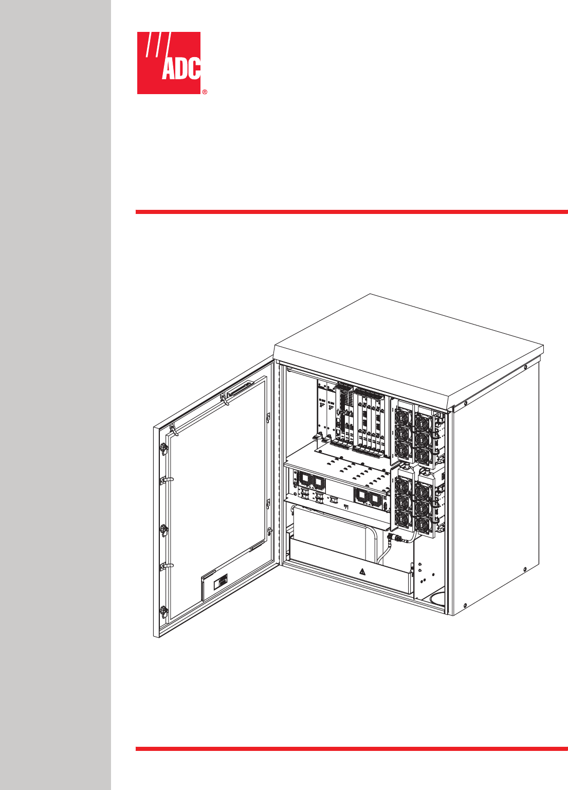
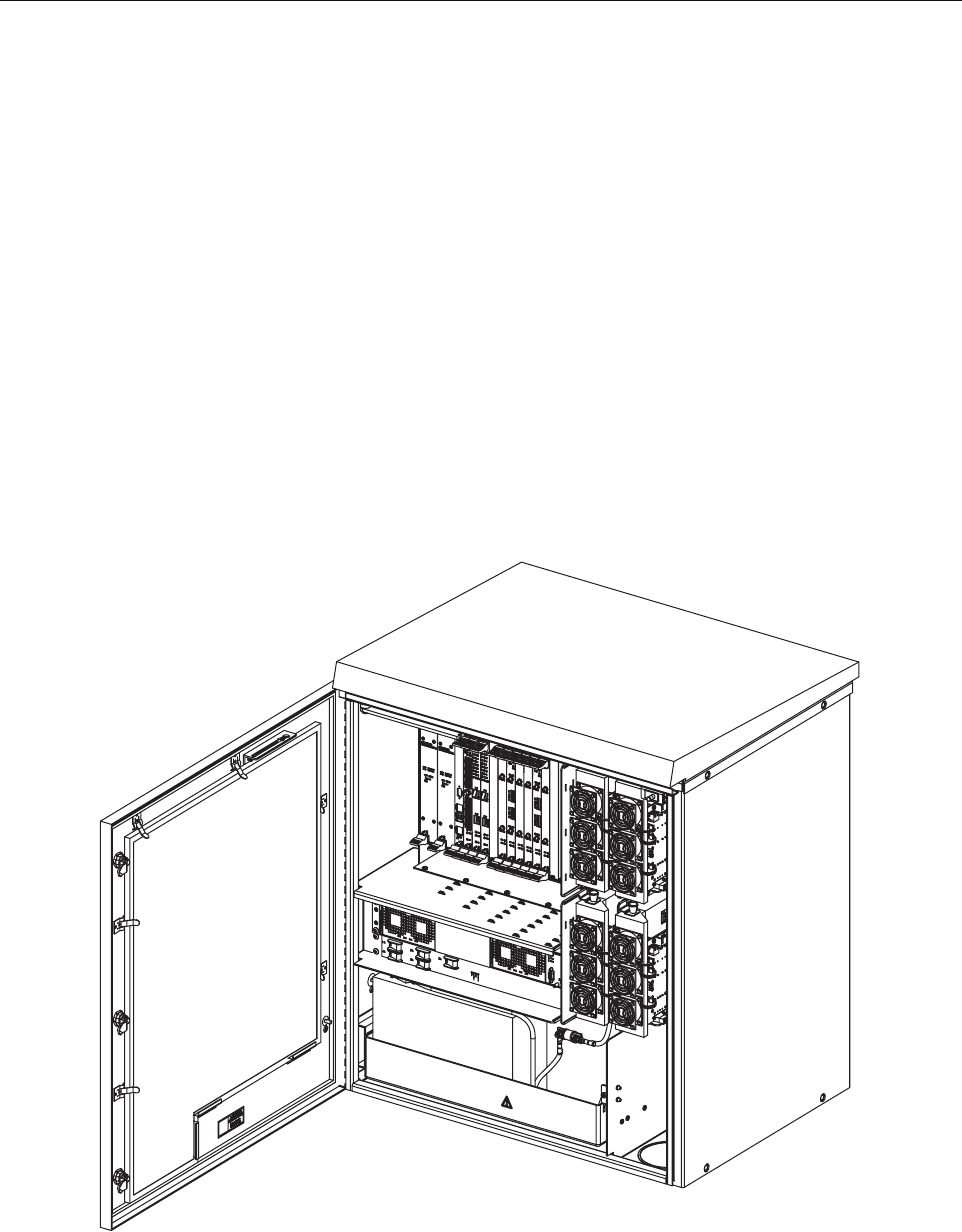
The RAN, shown in Figure 1, is the remote component in the Digivance NXD Multi-Band
Distributed Antenna System. The RAN is a pole-mounted or pad-mounted, weather-resistent
cabinet, housing electronic modules that operate on an internal cPCI backplane. Included are a
central processing unit, a system interface, an optical interface, optical to RF data converters,
RF multicouplers, and DC power supplies. The RAN also houses rectifiers, backup batteries,
power amplifiers, and optical wave division multiplexers. Optical and RF functions are both
required because the RAN exchanges data with the system Hub using an optical link and
exchanges data with wireless users using RF signals. Each RAN provides the system with an RF
antenna and can accommodate up to four bands (PCS A-F, SMR A, Cell A”/A, or Cell B/B’). Dual
RANs installed at the same location can accommodate up to eight bands using a common
antenna.
Figure 1. NXD RAN
21227-A

ADCP-75-210 • Issue 1 • March 2007
Page 2
© 2007, ADC Telecommunications, Inc.
1.2 System Function
The NXD Distributed Antenna System (DAS), in which the RAN is the remote component, is a
multi-frequency, multi-protocol RF access network providing microcellular Cellular and PCS
coverage via a distributed RF access system. In a typical configuration, such as shown in
Figure 2, multiple RANs are connected to a central Hub where multiple Base Transceiver
Station (BTS) interfaces are located. Signals received at the Hub are distributed to the RANs in
digital form by way of a fiber optical link. Within the RANs, the signals are converted from
digital to RF format to be transmitted from the RAN antennas. Signals also travel in a reverse
direction, from the RANs to the Hub, with a reverse data conversion.
Physically, the DAS consists primarily of electronic modules located in the Hub and RANs. At
the Hub, these modules are mounted in an equipment rack typically housed in a common
telecommunications structure with the base station electronics for Wireless Service Providers
(WSPs), either in the same room or nearby. These modules include high power attenuators, base
station modules, a power distribution unit, an Ethernet hub, a Hub reference module, an RF
chassis, and one or more digital chassis. The RAN electronic modules, mounted in the RAN
cabinet, perform the remote system functions of optical to RF data conversion and RF access.
These modules are described in subsequent topics within this product description. Digivance
Element Management System (EMS) software, running on a computer located at the Hub,
provides a graphical user interface to monitor system performance.
Figure 2. System Function
BTS BTS BTS BTS
Distribution Hub - EMS Server,
located on Hub Master, monitors
Hub Nodes and RANs
Digital
Fiber
Radio
Access
Node
21013-A
RF
SIGNALS
WIRELESS
SERVICE
PROVIDERS
(WSPs)
ADCP-75-210 • Issue 1 • March 2007
Page 3
© 2007, ADC Telecommunications, Inc.
1.3 High-Level View
The RAN consists of the main components shown in a high-level view in Figure 3. These
components include:
•RAN Cabinet: exterior shell of the RAN containing cable connection points, ground
studs, and slots or shelves supporting other RAN components.
•RAN Chassis: standard Compact PCI (cPCI) shelf capable of housing 21 industry
standard cPCI circuit card modules. The modules are plugged into a common backplane
providing data bussing between them.
•Related Electronics: including rectifiers, Power Amplifier Assemblies (PAAs), batteries,
multiplexers, and a circuit breaker panel.
All components called out in the figure except for the multiplexers are separately installable in
the field. In most cases, however, the RAN is shipped with a basic set of components having
been ordered in advance by the customer and installed in the factory.
Figure 3. High Level View
21281-A
RAN
CABINET
RAN CHASSIS
AND ELECTRONIC
MODULES
RELATED
ELECTRONICS:
RECTIFIERS
CIRCUIT
BREAKER
PANEL
BACKUP
BATTERIES
POWER
AMPLIFIER
ASSEMBLIES
(PAAs)
MULTIPLEXERS
ADCP-75-210 • Issue 1 • March 2007
Page 4
© 2007, ADC Telecommunications, Inc.
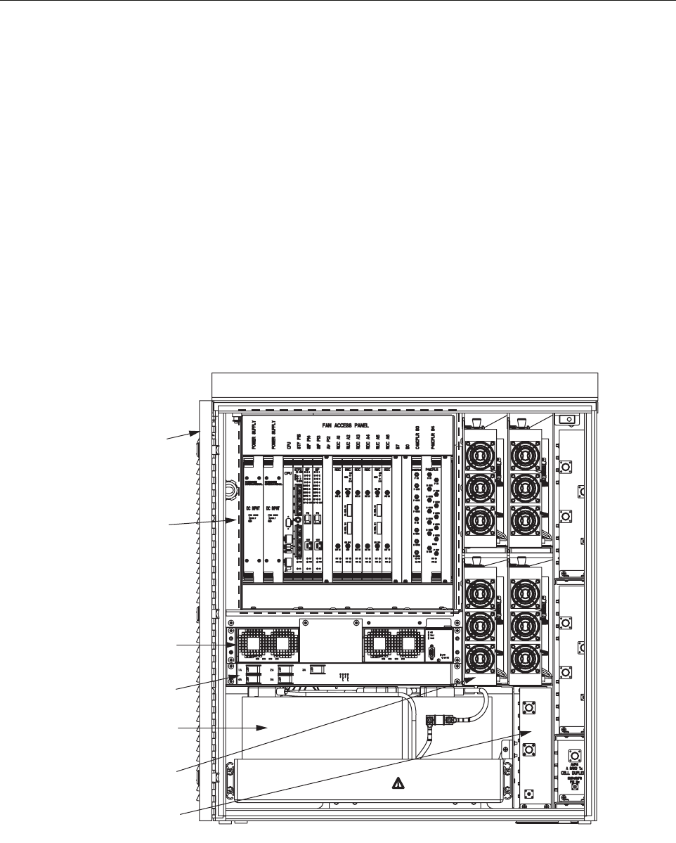
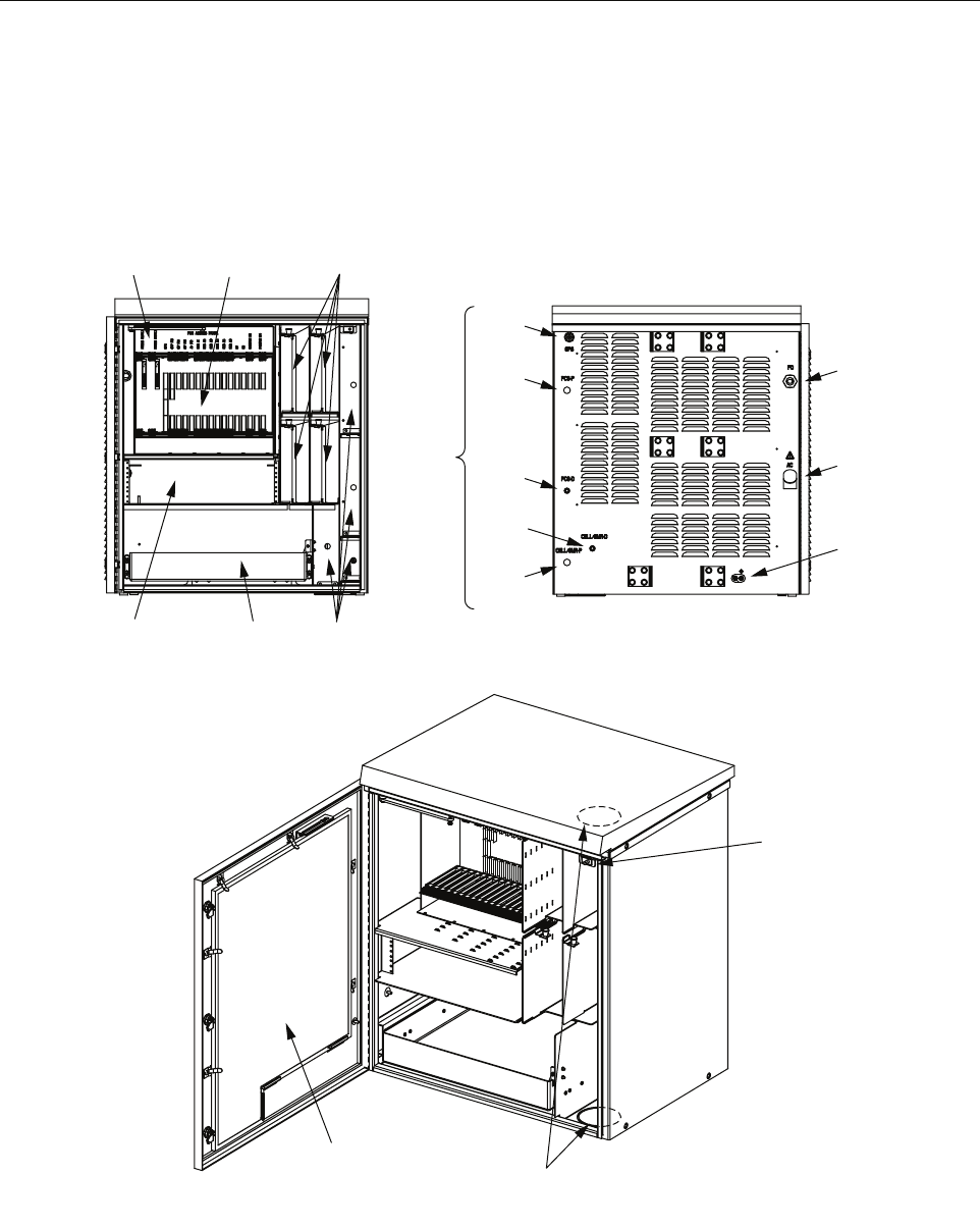
1.4 User Interface
The RAN user interface consists of the various connectors, fittings, mounting slots, power
cords, switches, and indicators that are of relevance to the user in installation and operation
procedures. The user interface is shown in Figure 4 and described in Table 1.
Figure 4. User Interface
FAN ACCESS
PANEL (1)
ELECTRONIC
MODULES (21)
POWER AMPLIFIER
ASSEMBLIES (4)
RECTIFIER
COMPARTMENT
(UP TO 3)
MUXs BATTERY
COMPARTMENT
(UP TO 4)
GPS
PCS-P
PCS-D
RF
CABLES
CELL/
SMR-D
CELL/
SMR-P
FIBER
PORT
PRIME
POWER
PORT
EARTH
GROUND
STUDS
REAR FRONT
AIR INLET
FILTER (1)
DOOR
ALARM
(1)
KNOCK-OUTS FOR
2nd RAN WIRING FROM
RAN A TO RAN B
21290-A

ADCP-75-210 • Issue 1 • March 2007
Page 5
© 2007, ADC Telecommunications, Inc.
Table 1. RAN Cabinet User Interface
COMPONENT WHY RELEVANT FOR MORE INFORMATION
Front View
Fan Access Panel Panel swings down providing access to
internal fan compartment; fans can be
replaced as required
Section 1.7.8 on Page 20
Electronic Modules Electronic modules have indicators
monitored by the user
Section 1.7 on Page 10
Electronic modules can be installed and
replaced as required
Section 4.1 on Page 57
Interconnection diagram summarizes
connections between modules
Figure 40 on Page 58;
Figure 41 on Page 59
Power Amplifier Assemblies PAAs have indicators monitored by
user
Section 1.9 on Page 25
PAAs can be installed or replaced as
required
Section 4.5 on Page 68
Rectifier Compartment Rectifiers have four unmarked LEDs Section 1.8 on Page 23
Rectifiers can be individually installed
and replaced as required
Section 4.3 on Page 66
Battery Compartment Batteries are packaged separately and
installed in a standard installation; they
can be replaced as required
Section 2.7.6 on Page 50
Rear Access
GPS, PCS-P, PCS-D,
CELL/SMR-D,
CELL/SMR-P
Connection points for RF cables con-
necting RAN with GPS antenna and RF
antenna.
Section 2.7.3 on Page 45;
Table 21 on page 47
Fiber Optic Cables Connection
Point
Connection point for fiber optic cable
from Hub
Section 2.7.4 on Page 47
Prime Power Contact Contact point for power ingress. RAN
requires 240 VAC, single phase, 20
Amps service, typically routed from a
pole- or pad-mounted junction box
Section 2.7.5 on Page 49
Earth Ground Studs Connection point for ground wires Section 2.7.2 on Page 44
Oblique View
Air Inlet Filter Filters are replaced per maintenance
schedule
Section 5.2 on Page 70
Door Alarm Replaceable switch
Knock-Outs for 2nd RAN Wir-
ing from RAN A to RAN B
When two RANs are installed at the
same location, an omnibus cable is
routed from RAN A to RAN B through
these knockout holes
Section 3 on Page 54
ADCP-75-210 • Issue 1 • March 2007
Page 6
© 2007, ADC Telecommunications, Inc.
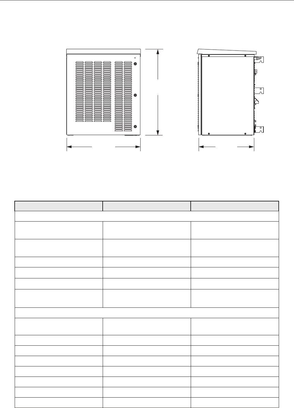
1.5 Dimensions and Specifications
Figure 5. NXD RAN Dimensions
Table 2. RAN Specifications
ITEM SPECIFICATION COMMENT
Physical and Mechanical
Dimensions (HxWxD) 36.5 x 31.0 x 24.0 inches
(92.7 x 78.7 x 60.1 cm)
See also Figure 5
Weight
with extended batteries (4)
300 lbs. (136.4 kg)
625 lbs. (284.1 kg)
RAN without batteries
Total RAN + 4 batteries
Color Putty white
Bands per box Up to 4
Boxes per RAN site Up to 2 RANs
RF connections RAN cabinet has
5 Type N plugs
Cable type: CommScope PN
540ANM or equivalent
Environmental and Thermal
Box thermal management External air Variable speed fans (PIC/PA
Assembly and cPCI)
Operating temperature -40 to +50 degrees C -40 to 122 degrees F
Cold-start temperature -20 to +50 degrees C -4 to 122 degrees F
Storage temperature -40 to +85 degrees C -40 to 185 degrees F
Internal air temperature 0 to 60 degrees C 32 to 140 degrees F
Weather resistance NEMA-3R
Operational humidity 95%
Acoustic emissions 63 dBA
21228-A
36.5 IN.
(92.7 CM)
31.0 IN.
(78.7 CM)
24.0 IN.
(60.1 CM)
FRONT SIDE

ADCP-75-210 • Issue 1 • March 2007
Page 7
© 2007, ADC Telecommunications, Inc.
Power
AC power ingress 240 VAC, 20 Amps, single phase
Battery backup options
extended
glitch
120 minutes
5 minutes
-48 volts
@25 degrees C (degrees F)
for four bands
RAN box power use 2700 Watts Max.
16 Amps Max.
cPCI rack power -48 VDC
Optical
Fiber cable ingress Nylon connector accommodates
cable diameters in range 0.38-
0.50 inches (0.97-1.27 cm).
For larger cable sizes, refer to the
note in Section 1.6.2 on Page 9.
Fiber type Corning SMF-28 or equivalent
Optical connectors LC Standard on SFP transceivers
Insertion loss 0.2 dB Typical, 0.4 dB Max.
Number of fibers required 1-4 fiber runs per RAN
Fiber configuration Star (point to point) or ring Ran ring limited to 3 SIFs
Fiber data link protocol OC-48
Wavelengths per fiber
with WDM option
with CWDM option
1 (1310 nm)
2 (1310/1550)
8 (1470-1610)
Without WDM/CWDM option
20 nm increments (ITU-GRID)
Optical transceiver type SFP Dual LC connector
Optical Tx power -3 dBm Max, -10 dBm Min. Finistar FTRJ-1320-1
(or equivalent)
Optical Rx sensitivity -22 dBm Typical, -18 dBm Max.
Optical link margin 2 dB Estimated
Optical link loss 6 dB Estimated
Optical Rx saturation level -3 dBm Min. Max. operational power
Optical Rx damage level -3 dBm Min. Max survivable power
Optical safety class 1ANSI Z 136.2
RF
Tuning frequency
PCS band
Cellular band
SMR 800 band
SMR 900 band
Receive Path
1850-1910 MHz
824-849 MHz
806-824 MHz
896-901 MHz
Transmit Path
1930-1990 MHz
869-894 MHz
851-869 MHz
935-940 MHz
Instantaneous bandwidth 15 MHz
Receiver noise figure
PCS band
Cellular band
6 dB
5 dB
Measured at Hub output connec-
tor (BIM, RxP) without BTS at 10
dB gain and a single RAN
Table 2. RAN Specifications
ITEM SPECIFICATION COMMENT

ADCP-75-210 • Issue 1 • March 2007
Page 8
© 2007, ADC Telecommunications, Inc.
1.6 RAN Cabinet
The RAN cabinet is a NEMA-3R enclosure designed to protect its electronic components from
weather and human tampering. The cabinet is weather-tight but contact with salt-air mist should
be avoided as it may decrease the mean time between failure of some components. The cabinet
has ventilation openings to allow entry of cool air and escape of hot air. The cabinet provides
Input IP3 -21 dBm Two tone tests at -56 dBm
Received signals
In band
Out of band +/- 8.5 MHz
Out of band +11/-13 MHz
Out of band +13/-16 MHz
-41 dBm
-3 dB
-43 dB
-83 dB
RDC capability (at cabinet input)
A/D clip level, single RF channel
Selectivity (function of SAW filter)
Selectivity
Selectivity
Automatic gain control
Detector integration time
Attack time
Decay time
Gain control range
10 usec
0 usec
0 usec
30 dB
Activated if A/D clips, changes
gain of A/D and gain in digits.
Design ensures analog gain and
digital gain change will be timed
correctly. 15 dB noise figure at
-14 dB gain
Gain in series with BTS -10 to +10 dB Lower limit for simulcast with a
host tower site, the max reduces
effect of cascaded noise figure
Gain parallel to BTS 0 to +30 dB Allows injection after BTS
amplifiers
Gain stability +/- 2dB Over temperature, frequency, and
aging valid for input signals
below AGC threshold
System Bandwidth
Forward Path
Reverse Path
15 MHz block increments
15 MHz block increments
Impedance 50 ohm
Output Power
Cellular/SMR 10 Watt MCPA
PCS 20 Watt MCPA
6.5 Watts (+38 dBm) composite
12.5 Watts (+41 dBm) composite
At antenna port
At antenna port
Gain resolution 1 dB
Gain measurement Configured at startup using fac-
tory calibration of modules and
user data
Note: The Manufacturer’s rated output power of this equipment is for single carrier
operation. For situations when multiple carrier signals are present, the rating would have
to be reduced by 3.5 dB, especially where the output signal is re-radiated and cause
interference to adjacent band users. The power reduction is to be by means of input power
or gain reduction and not by an attenuator at the output of the device.
Table 2. RAN Specifications
ITEM SPECIFICATION COMMENT

ADCP-75-210 • Issue 1 • March 2007
Page 9
© 2007, ADC Telecommunications, Inc.
termination points for the coaxial antenna cable, fiber optic cable, ground cable, and AC cable.
The cabinet has inbuilt AC power surge protection and limited storage for fiber optic cables.
1.6.1 Mounting
The RAN cabinet may be mounted on a wood pole or on a concrete pad. Mounting bracket kits
(available from ADC) are required for each type of installation.
1.6.2 Fiber Optic Cable Entry
A nylon connector is provided on the rear of the RAN cabinet for routing a fiber optic cable into
the cabinet. The cord connector provides cable strain relief and a watertight seal at the fiber
optic cable entry point. As the connector nut is tightened, a soft neoprene bushing compresses to
tightly grip the cable without applying excessive force to the fibers. The connector
accommodates cables of a diameter in the range .38 to .50 inches (.97 to 1.27 cm).
In a typical installation, the connectorized end of a multi-fiber OSP cable is routed into the
cabinet through the cord connector and the individual fibers are connected to the optical
transceiver on the Synchronous Interface Card (SIF). Excess slack is stored inside the cabinet.
The stub end of the cable is routed to an external splice enclosure (not provided) for splicing to
the outside plant fiber optic cable.
1.6.3 Antenna Cable Connections
Five N-type plugs are provided on the rear of the RAN cabinet for connecting the antenna
coaxial cables. On the inside of the cabinet, coaxial jumper cables (included with the cabinet)
are used for connecting to the antenna port on the appropriate multiplexer.
1.6.4 AC Power Wiring Entry and Grounding
The NXD RAN uses 240 VAC power. A one inch (2.54 cm), 90 degree rigid elbow conduit
fitting is provided on the rear of the cabinet. The conduit should be routed to an external
junction box (not provided). It is suggested that an external AC outlet (not provided) be installed
near the cabinet to power test equipment and power tools. The AC source should supply 50/60
Hz, single-phase power through a circuit breaker rated at 20 Amps.
1.6.5 Ventilation
Ventilation openings are provided in the front door of the RAN cabinet to permit entry of air for
cooling. A filter removes dirt particles so that only clean air enters the cabinet. The heated air
exits the cabinet through the rear side. The four PAAs are each equipped with three cooling fans
that pull air through the module and exhaust it to the rear of the cabinet. A fan assembly at the
top of the RAN chassis forces the air out the rear side of the cabinet.
Note: If the installer has a larger cable, the manufacturer (Hubbell Inc.) makes bushings
that fit this connector in the following size ranges: .500-.625, .625-.750, .750-.875, .875-
1.00, 1.00-1.125 inches.
ADCP-75-210 • Issue 1 • March 2007
Page 10
© 2007, ADC Telecommunications, Inc.
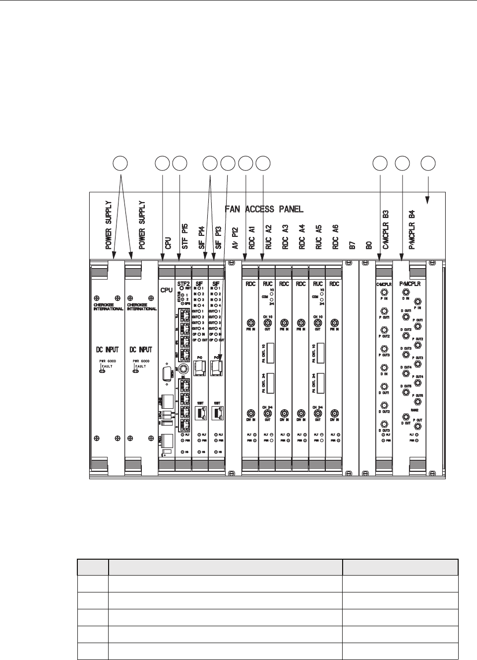
1.7 RAN Chassis and Electronic Modules
The RAN chassis, shown in Figure 6, is a standard Compact PCI (cPCI) shelf capable of
housing 21 industry standard cPCI circuit cards (called “electronic modules” in this manual).
The backplane supports the basic cPCI functions and it has been extended to allow the routing
of DIFTM, reference clocks and I2C signals between I2C modules. The RAN chassis also houses
cooling fans within the Fan Access Panel on the top of the chassis. Table 3 identifies the
electronic modules using the callout reference numbers from Figure 6.
Figure 6. RAN Chassis
Table 3. RAN Chassis Electronic Modules
REF # MODULE NAME FOR DETAILS REFER TO
1cPCI Power Supplies Section 1.7.1 on Page 12
2Central Processing Unit (CPU) Section 1.7.2 on Page 13
3System Interface (STF2) Section 1.7.3 on Page 14
4Synchronous Interface (SIF) Section 1.7.4 on Page 15
5Small Form-Factor Pluggable Optical Transceiver (SFP) Section 1.7.5 on Page 17
21282-A
123 67 891045
ADCP-75-210 • Issue 1 • March 2007
Page 11
© 2007, ADC Telecommunications, Inc.
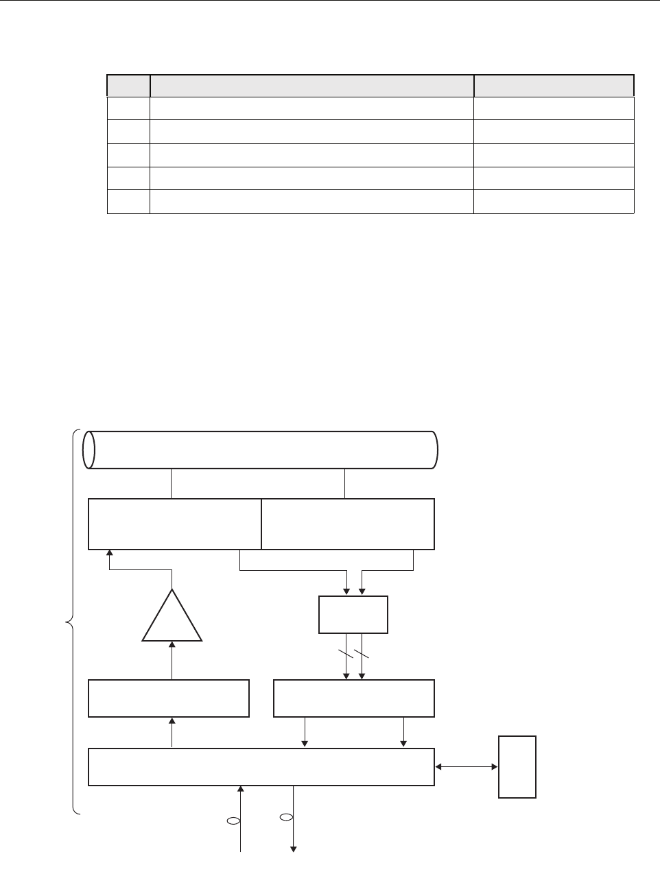
Figure 7 is a schematic showing the data flow in the RAN chassis, as represented by the PCS-A
band. As shown, data flows in two directions, from the Hub through the RAN to the antenna,
and from the antenna through the RAN back to the Hub. In each direction, data conversion
occurs, with optical data “upconverted” to RF data in the up direction in the schematic, and RF
data “downconverted” to optical data in the down direction. In an up direction, the RUC module
converts Digitized Intermediate Frequency (DIF) data into PCS, Cellular, and SMR frequency
RF bands. The RF signals are amplified and then transmitted from the RF antenna. In the down
direction, the RDC module converts PCS, Cellular, and SMR frequency bands into DIF data.
The overall series of events is managed by the CPU using an Ethernet connection to the chassis
backplane.
Figure 7. RAN Chassis Schematic
6RAN Down Converter (RDC or RDC2) Section 1.7.6 on Page 17
7RAN Up Converter (RUC2.X or RUC3) Section 1.7.7 on Page 19
8800 MHz Multi-Coupler Section 1.7.9 on Page 20
91900 MHz Multi-Coupler Section 1.7.10 on Page 22
10 Fan Access Panel Section 1.7.8 on Page 20
Table 3. RAN Chassis Electronic Modules
REF # MODULE NAME FOR DETAILS REFER TO
SIF
Pri Div
Pri Div
1900
MUL
DIF
DIF
RF
1900-P 1900-D
DIF
RUC RDC
CPU
Ethernet
Fiber Fiber
MCPA
RAN
H
U
B
MB
ANT
RAN = Radio Access Node
DIF = Digital Intermediate
Frequency
SIF = Synchronous Interface
RUC = RAN Up Converter
MCPA = Munti-Carrier Power
Amplifier
MB ANT = Multi Band Antenna
MUL = Multi-Coupler
RDC = RAN Down Converter
21777-A
AB FRX
ANT
PCS QUADPLEXER
DECRX
ANT
PCS QUADPLEXER
66
ADCP-75-210 • Issue 1 • March 2007
Page 12
© 2007, ADC Telecommunications, Inc.
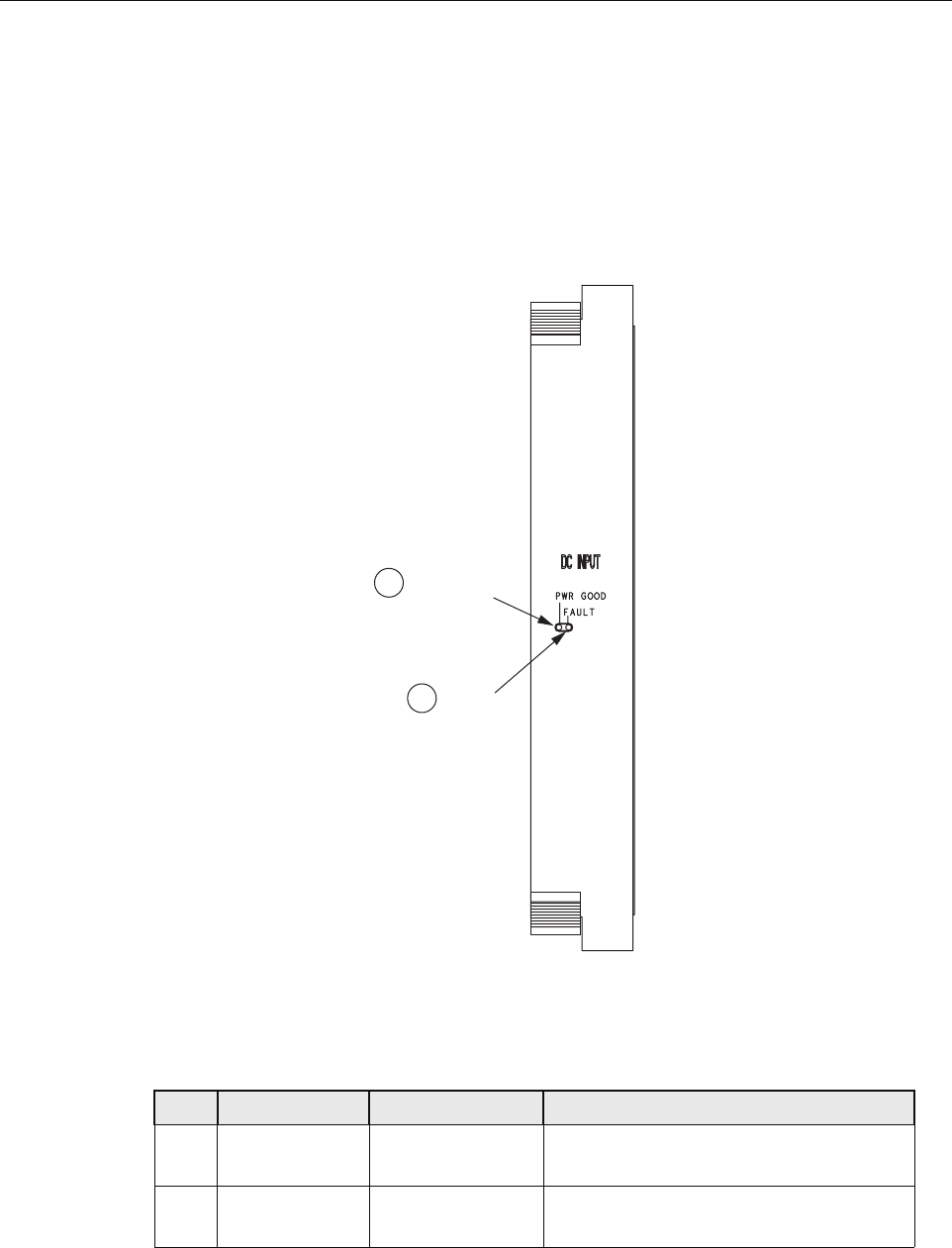
1.7.1 cPCI Power Supply Modules
The Compact PCI (cPCI) Power Supply Modules provide +/-12V, 5V, and 3.3V DC power to
the cPCI backplane for use by the cPCI electronic modules. Each RAN requires one power
supply module. Two modules can be used to provide redundancy if desired. These modules are
hot swappable. Figure 8 shows the cPCI Power Supply Module faceplate. Table 4 describes the
faceplate components called out in the figure.
Figure 8. cPCI Power Supply Module Faceplate
CPU
Table 4. cPCI Power Supply Module Faceplate
Ref # DESIGNATION DEVICE FUNCTIONAL DESCRIPTION
1PWR GOOD Single-color LED
(green)
Power Good. Turns green when module has
power
2FAULT Single-color LED
(red)
Fault. Turns red when module has
insufficient power to perform its function
21240-A
POWER
GOOD LED
FAULT
LED
1
2
ADCP-75-210 • Issue 1 • March 2007
Page 13
© 2007, ADC Telecommunications, Inc.
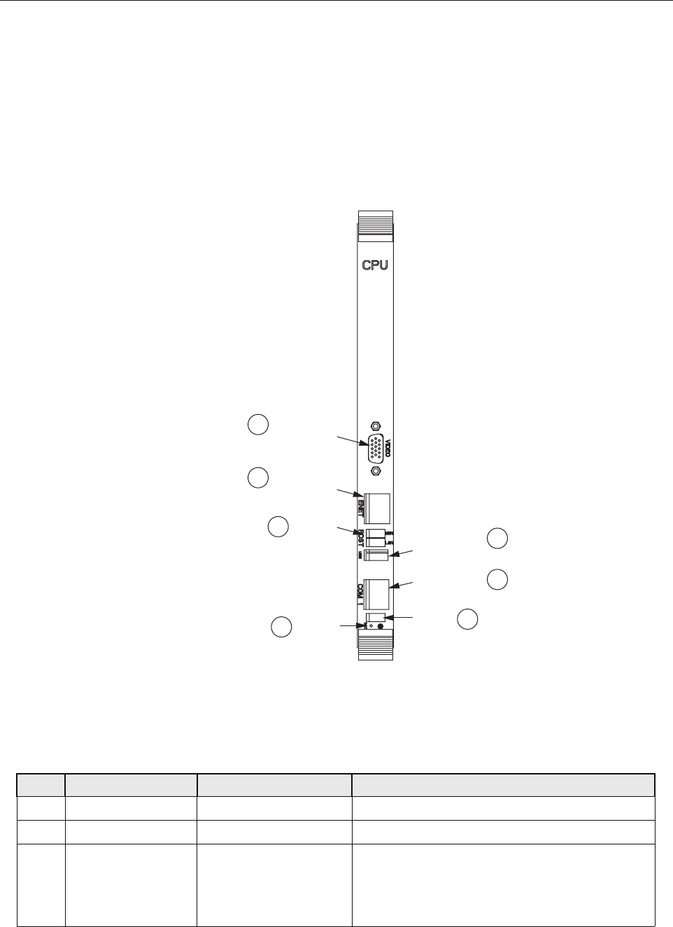
1.7.2 Central Processing Unit (CPU) Module
The Central Processing Unit (CPU) Module is a cPCI-based, single-board x86 computer with
disk running on a Linux operating system. Each RAN chassis has one CPU module. The CPU
runs a process management program that manages all RAN hardware including RF and digital
equipment. The program also manages RF signal gain and monitors signal presence and quality.
Figure 9 shows the CPU module faceplate. Table 5 describes the faceplate components called
out in the figure.
Figure 9. CPU Module Faceplate
CPU
Table 5. CPU Module Faceplate Components
REF # DESIGNATION DEVICE FUNCTIONAL DESCRIPTION
1USB1 USB connector Front panel input/output for USB connectivity
2COM 1 RJ-11C connector Front panel interface for COM1
3(Unmarked) Status LEDs LED 1 is POST (red on start-up, turns green on
successful completion of start-up self test); LED 2
& 3 are undefined; LED 4 (blinking green) indicates
disk or flash memory activitity
21251-A
VIDEO
CONNECTOR
ETHERNET
CONNECTOR
UNIVERSAL
SERIAL BUS
CONNECTOR
COM 1
CONNECTOR
STATUS
LEDs
1
7
6
5
4
2
3
ACTICITY
LEDs
RESET
BUTTON

ADCP-75-210 • Issue 1 • March 2007
Page 14
© 2007, ADC Telecommunications, Inc.
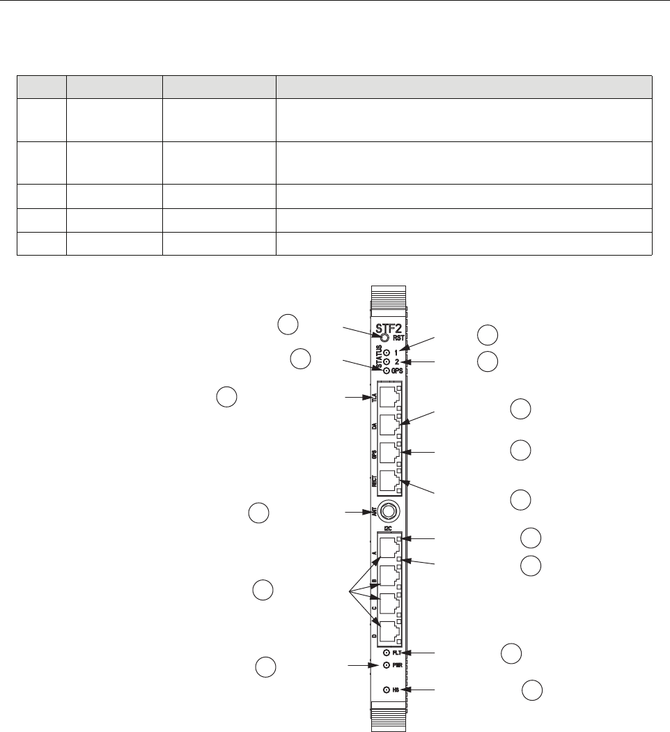
1.7.3 System Interface (STF2) Module
The System Interface (STF2) Module is a cPCI electronic module that provides the CPU and
other electronic modules with the ability to communicate with one another using the four I2C
buses on the cPCI backplane. One STF2 is used per RAN. The STF2 also has the GPS antenna
input port located in the center of the module faceplate. STF2 modules are specified according
to the number of qualifying communications devices being utilized. Table 6 describes the
module faceplate components. Figure 10 shows the location of the faceplate components.
4RST Recessed switch Reset. Used to manually reset the CPU
5POST Single-color LEDs
(yellow)
Post. Top four LEDs give status of CPU during initial
boot process; bottom four give board operation status
6ENET RJ-45 connector with
single-color LEDs (green
and yellow)
Ethernet. 10 BaseT. Connects to RJ-45 connector on
SIF module (10BT port) using cable 1001478P001.
Connection status (green) and 100 BT (yellow)
7VIDEO 15-PIN VGA connector Video. Not used by Digivance system
Table 6. System Interface Module Faceplate Components
REF # DESIGNATION DEVICE FUNCTIONAL DESCRIPTION
1RST Recessed switch Reset. Used to halt operation of the CPU operating system. A
power ON reset is required to restart the CPU
2STATUS 1 Single-color LED
(yellow)
Reserved for future use. Indicator turns yellow when the CPU is
not installed or has malfunctioned
3STATUS 2 Single-color LED
(yellow)
Reserved for future use. Indicator turns yellow when the CPU is
not installed or has malfunctioned
4STATUS GPS Single-color LED
(green)
Indicator showing that 1PPS signal is available. Led toggles once
per second (RAN only)
5DA RJ-45 connector Door Alarm. Input using cable 1001474P001; small LED on this
connector lights (red) when door is open
6GPS RJ-45 connector Not used
7RECT RJ-45 connector Rectifier. Communications to rectifier using cable 1001476P001
8(Unmarked) Single-color LED
(red)
I2C Error LEDs. One on each I2C RJ-45 connector. Indicator turns
red when there is no response on port
9(Unmarked) Single-color LED
(green)
I2C Comm LEDs. One on each I2C RJ-45 connector. Indicator
turns green when an I2C message sent on the port
10 FLT Single-color LED
(red)
Fault. Indicator turns red when module has failed or upon startup
until the module has completed initialization
Table 5. CPU Module Faceplate Components
REF # DESIGNATION DEVICE FUNCTIONAL DESCRIPTION
ADCP-75-210 • Issue 1 • March 2007
Page 15
© 2007, ADC Telecommunications, Inc.
n
Figure 10. System Interface Module Faceplate
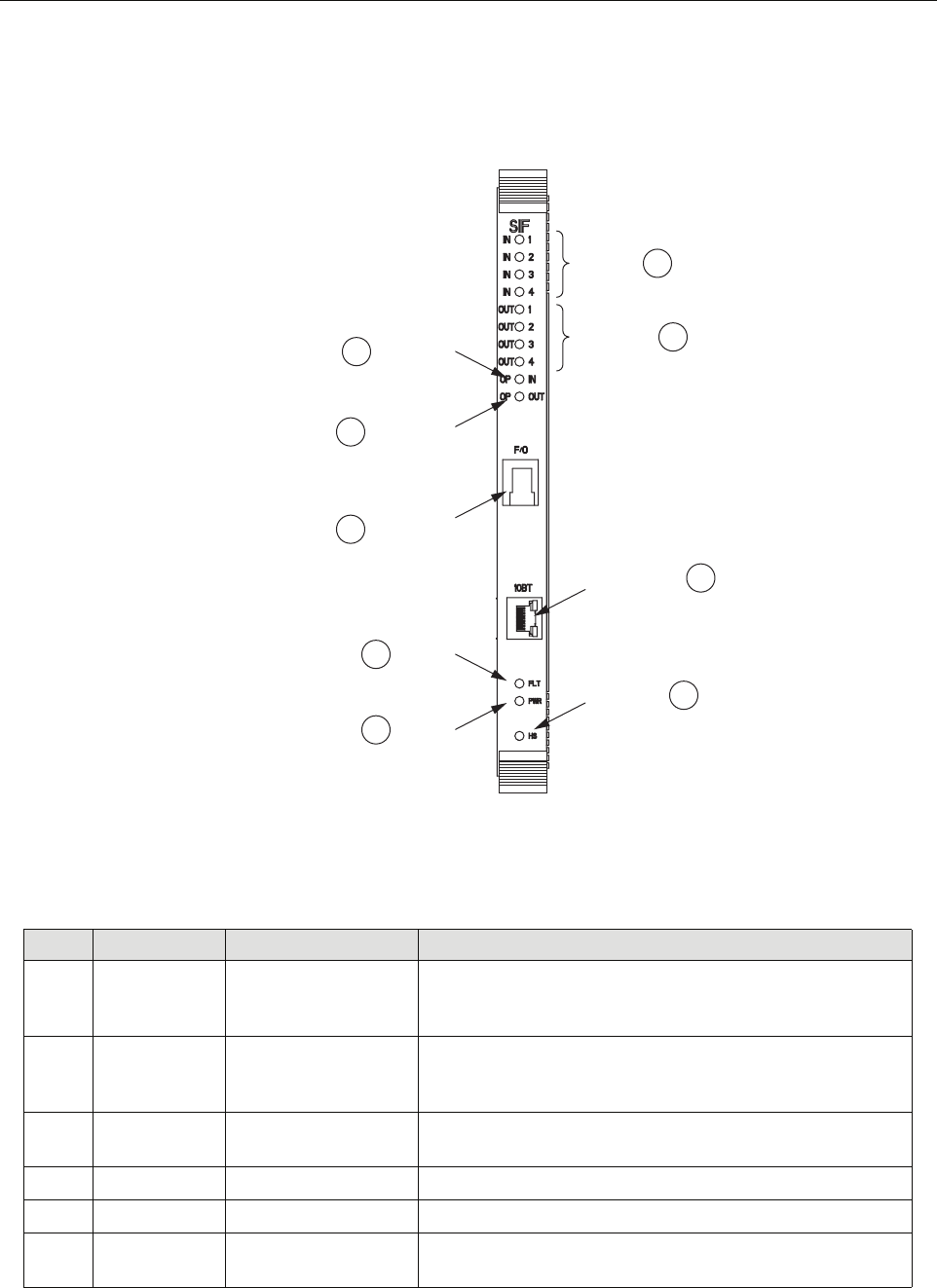
1.7.4 Synchronous Interface (SIF) Module
The Synchronous Interface (SIF) Module provides the optical interface between the Hub and
the RAN. This interface provides for exchange of digitized RF signal information and 10BaseT
Ethernet command and control information. Each RAN can have up to two SIFs, each handling
two bands with diversity receive paths.
11 HS Single-color LED
(blue)
Not used
12 PWR Single-color LED
(green)
Power. Indicator turns green when module has power
13 I2C A-D RJ-45 connectors I2C (Bus). Connectors to I2C buses
14 ANT SMA connector Antenna. Input for GPS antenna signal
15 TLA RJ-45 connector Tower Light Alarm (unused)
Table 6. System Interface Module Faceplate Components
REF # DESIGNATION DEVICE FUNCTIONAL DESCRIPTION
21253-A
GPS
LED
RESET
SWITCH STATUS
LED 1
4
15
1
2
STATUS
LED 2
TOWER LIGHT
ALARM CONNECTOR DOOR ALARM
CONNECTOR
I2C
CONNECTOR
I2C COMM LED
3
5
GPS COMMS
CONNECTOR 6
RECTIFIER
COMMS
CONNECTOR
7
8
POWER LED
12
FAULT LED 10
HOT SWAP LED 11
I2C ERROR LED
9
14
13
GPS ANTENNA
CONNECTOR
(RAN ONLY)
ADCP-75-210 • Issue 1 • March 2007
Page 16
© 2007, ADC Telecommunications, Inc.
The SIF module is equipped with a small form-factor pluggable optical transceiver (SFP)
module. (For more information on the SFP, see Section 1.7.5.) Figure 11 shows the SIF module
faceplate. Table 7 describes the faceplate components.
Figure 11. Synchronous Interface Module Faceplate
Table 7. Synchronous Interface Module Faceplate Components
REF # DESIGNATION DEVICE FUNCTIONAL DESCRIPTION
1IN 1-4 Tri-color LED
(green/yellow/red)
In. Indicates if DIF input is not enabled (off), good (green),
degraded (yellow), clock issue (blinking), or no DIF tone
lock or unused channel (red)
2OUT 1-4 Tri-color LED
(green/yellow/red)
Out. Indicates if DIF output is not enabled (off), good
(green), degraded (yellow), clock issue (blinking), or bad
data on output of unused channel (red)
310BT RJ-45 connector 10BaseT (Ethernet). Communications between SIF and CPU
using cable 1001478P001
4HS Blue LED Not used
5PWR Green LED Power. Lights when module has power
6FLT Red LED Fault. Lights when module has failed and during start-up
until module is initialized
21238-A
DIF OUTPUT
LED 1-4
ETHERNET
CONNECTOR
2
3
DIF INPUT
LED 1-4 1
HOT SWAP
LED
POWER
LED
FAULT
LED
4
5
6
OPTICAL
INPUT LED
9
OPTICAL
OUTPUT LED
8
SFP FIBER
OPTIC
CONNECTOR
7
ADCP-75-210 • Issue 1 • March 2007
Page 17
© 2007, ADC Telecommunications, Inc.
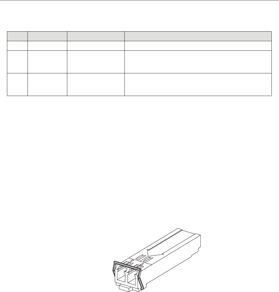
1.7.5 Small Form-Factor Pluggable (SFP) Optical Transceiver
The Small Form-Factor Pluggable (SFP) Optical Transceiver, located on the SIF module and
shown in Figure 12, provides the optical interface between the Hub equipment and the RAN
hardware. The SFP has a laser transmitter and an optical receive detector.
The Digivance NXD system uses industry standard SFP optics which offer a number of
configuration options depending on the requirements of the project. The SFP modules are
available separately and may or may not be installed in the SIF depending on the configuration
ordered. The SFP module is specified as up to two per RAN and is able to support two bands
with receive diversity.
The standard SFP module has an optical budget of 9 dB. The SFP module is factory and field
replaceable with optical transceivers having extended optical budgets up to 26 dB or Coarse
Wave-Division Multiplexing (CWDM) optical wavelengths.
Figure 12. Small Form-Factor Optical Transceiver
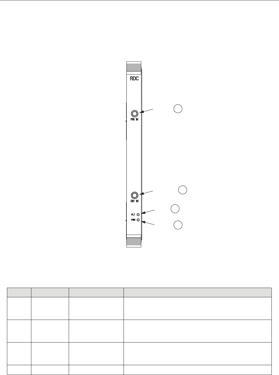
1.7.6 RAN Down Converter (RDC or RDC2) Module
The RAN Down Converter (RDC or RDC2) Module is a cPCI electronic module housing a
dual-diversity wideband RF receiver. This module takes PCS, Cellular, SMR A, and SMR B
signals from a primary and secondary antenna (via the appropriate multicoupler) and converts
the signals to Digitized Intermediate Frequency (DIF).
7F/O Dual-LC connectors Fiber/Optics. Optics connector on SFP optical transceiver
8OP IN Tri-color LED
(green/yellow/red)
Optical In. Indicates input status of the SFP interface: not
enabled (off), good (green), degraded (yellow), or bad output
signals (red)
9OP OUT Tri-color LED
(green/yellow/red)
Optical Out. Indicates output status of SFP interface: not
enabled (off), good (green), degraded (yellow), or bad fram-
ing, bad parity, no signal, or no signal lock (red)
Table 7. Synchronous Interface Module Faceplate Components
REF # DESIGNATION DEVICE FUNCTIONAL DESCRIPTION
21316-A
ADCP-75-210 • Issue 1 • March 2007
Page 18
© 2007, ADC Telecommunications, Inc.
This module also provides a CW test tone for use in reverse continuity testing. The RF signals
are input into the module by way of coax cables terminated with SMA connectors on the
faceplate (at the ports labeled PRI IN and DIV IN). Figure 13 shows the module faceplate.
Table 8 describes the module faceplate components called out in the figure.
Figure 13. RAN Down Converter Module Faceplate
Table 8. RAN Down Converter Module Faceplate Components
REF # DESIGNATION DEVICE FUNCTIONAL DESCRIPTION
1PRI IN SMA connector Primary In. Receives RF primary output from either C/PMC-
PLR or P/MCPLR module. Connection is made using cable
1955000P081
2DIV IN SMA connector Diversity In. Receives RF diversity output from either C/
PMCPLR or P/MCPLR module. Connection is made using
cable 1955000P081
3FLT Red LED Fault. Lights when module has failed and during start-up until
module has initialized; blinks after module receives a system
clock and is awaiting initialization
4PWR Green LED Power. Lights when module has power
21236-A
PRIMARY
IN
DIVERSITY
IN
FAULT
LED
POWER
LED
1
2
3
4
ADCP-75-210 • Issue 1 • March 2007
Page 19
© 2007, ADC Telecommunications, Inc.
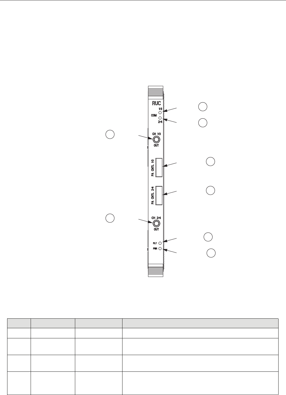
1.7.7 RAN Up Converter (RUC2.X or RUC3) Module
The RAN Up Converter (RUC2.X or RUC3) Module is a cPCI electronic module that takes
Digitized Intermediate Frequency (DIF) signals from a DIF signal generated by the SIF and
converts the signals to RF (PCS, Cellular, SMR A, and SMR B frequency bands). Each module
supports two simultaneous bands via wideband outputs. The RUC also provides clocking for its
neighboring RDC. For module faceplate and callouts, see Figure 14 and Table 9.
Figure 14. RAN Up Converter Module Faceplate
Table 9. RAN Up Converter Module Faceplate Components
REF # DESIGNATION DEVICE FUNCTIONAL DESCRIPTION
1CH 1/3 OUT SMA connector Channel 1/3 Out*
2COM 1/3 Yellow LED COM Port 1/3. Turns yellow when DIF is locked to SIF channel
1 or 3*
3COM 2/4 Yellow LED COM Port 2/4. Turns yellow when DIF is locked to SIF channel
2 or 4*
4PA CNTL 1/3 I2C flatpack
connector
PA Control Channel 1 or 3. Outputs control data to the PIC card
on the PAA for the channel being provided (using cable
1955000P079)*
21234-A
CHANNEL
1/3 OUT
COM 1/3
1
2
COM 2/4 3
CHANNEL
2/4 OUT
8
FAULT LED 6
POWER LED 7
PA CNTL 1/3 4
PA CNTL 2/4 5
ADCP-75-210 • Issue 1 • March 2007
Page 20
© 2007, ADC Telecommunications, Inc.
* An RUC in slot A2 will connect to PAAs 1 and 2. An RUC in slot A5 will connect to PAAs 3 and 4.
Therefore, the RUC front panel indicators of 1/3 and 2/4 will map to PAAs 1 and 2 connections in slot
A2 and PAA 3 and 4 connections in slot A5.
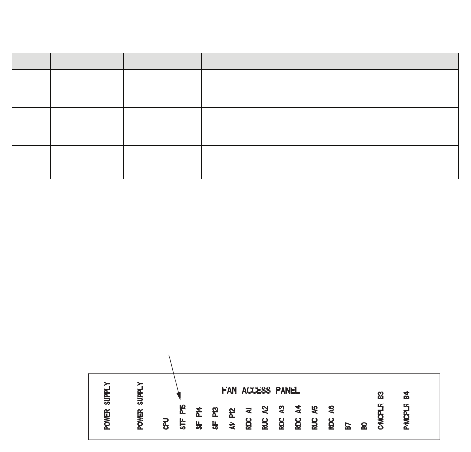
1.7.8 Fan Access Panel
The Fan Access Panel, shown in Figure 15, has a hinged front panel that swings down providing
access to the two fans cooling the RAN chassis. These fans are user-replaceable. This panel has
labels identifying the electronic modules located in the cPCI shelf below the panel.
Figure 15. Fan Access Panel
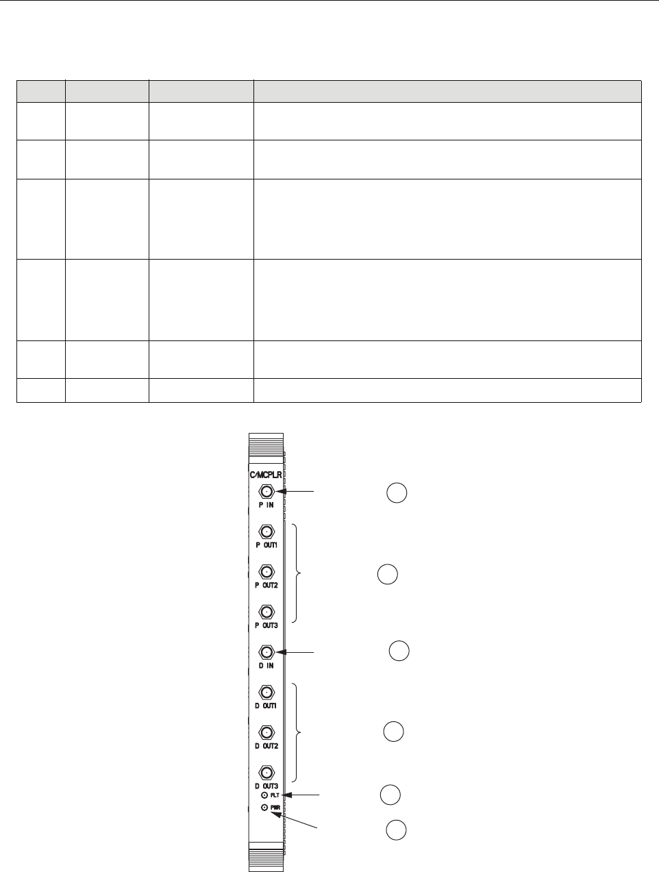
1.7.9 800 MHz Multicoupler (C/MCPLR)
The 800 MHz (C/MCPLR) Module is a cPCI electronic module that houses the dual-diversity,
receive unit for the 800 MHz bands. This module interfaces to the multiplexer system and
contains the front end low noise amplifiers for the reverse path. The module has six outputs
(Cell bands A, B, and 800 MHz, with diversity).
Figure 16 shows the location of the faceplate components. Table 10 describes the faceplate
components.
5PA CNTL 2/4 I2C flatpack
connector
PA Control Channel 2 or 4. Outputs control data to the PIC card
on the PAA for the channel being provided (using cable
1955000P079)*
6FLT Red LED Fault. Turns red when the module has failed. Indicator is lit dur-
ing start-up until module has initialized. Indicator will blink
after module receives system clock and is awaiting initialization
7PWR Green LED Power. Turns green when module has power
8CH 2/4 OUT SMA connector Channel 2 or 4 OUT*
Table 9. RAN Up Converter Module Faceplate Components
REF # DESIGNATION DEVICE FUNCTIONAL DESCRIPTION
21318-A
LABELS FOR CPCI
ELECTRONIC MODULES
ADCP-75-210 • Issue 1 • March 2007
Page 21
© 2007, ADC Telecommunications, Inc.
Figure 16. C/MCPLR Module Faceplate
Table 10. C/MCPLR Modules Faceplate Components
REF # DESIGNATION DEVICE FUNCTIONAL DESCRIPTION
1P IN SMA connector Primary In. Receives RF primary reverse path input from primary
antenna
2D IN SMA connector Diversity In. Receives RF diversity reverse path input from second-
ary antenna
3P OUT SMA connectors Primary Out. 3 primary outputs (Cell bands A, B, and SMR-A). Each
output being used connects to one RDC electronic module, either in
the same RAN or in the extension RAN if present. Connection is
made using cable 1955000P081
4D OUT SMA connectors Diversity Out. 3 diversity outputs (Cell bands A, B, and SMR-A).
Each output being used connects to one RDC electronic module,
either in the same RAN or in the extension RAN if present. Connec-
tion is made using cable 1955000P081
5FLT Red LED Fault. Lights when module has failed and during start-up until mod-
ule has initialized
6PWR Green LED Power. Lights when module has power
21242-A
2
1
3
5
6
4
DIVERSITY IN
CONNECTOR
PRIMARY IN
CONNECTOR
PRIMARY OUT
CONNECTORS
DIVERSITY OUT
CONNECTORS
FAULT LED
POWER LED
ADCP-75-210 • Issue 1 • March 2007
Page 22
© 2007, ADC Telecommunications, Inc.
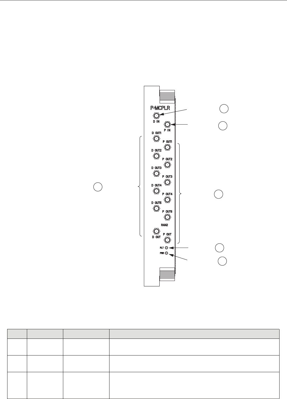
1.7.10 1900 MHz Multicoupler (P/MCPLR)
The 1900 MHz (P/MCPLR) Module is a cPCI electronic module that houses the dual-diversity,
receive unit for the PCS band. This module interfaces to the multiplexer system and contains the
front end low noise amplifiers for the reverse path. The PCS band has 12 outputs (bands A-F,
with diversity). Figure 17 shows the location of the faceplate components. Table 11 describes
the module faceplate components.
Figure 17. P/MCPLR Modules Faceplates
Table 11. P/MCPLR Modules Faceplate Components
REF # DESIGNATION DEVICE FUNCTIONAL DESCRIPTION
1P IN SMA connector Primary In. Receives RF primary reverse path input from primary
antenna
2D IN SMA connector Diversity In. Receives RF diversity reverse path input from secondary
antenna
3P OUT SMA connectors Primary Out. 6 primary outputs (bands A-F); each output being used
connects to one RDC module, in either same RAN or extension RAN
if present. Connection is made using cable 1955000P081
21245-A
2
1
3
5
6
4
DIVERSITY IN
CONNECTOR
PRIMARY IN
CONNECTOR
PRIMARY OUT
CONNECTORS
DIVERSITY OUT
CONNECTORS
FAULT LED
POWER LED
ADCP-75-210 • Issue 1 • March 2007
Page 23
© 2007, ADC Telecommunications, Inc.
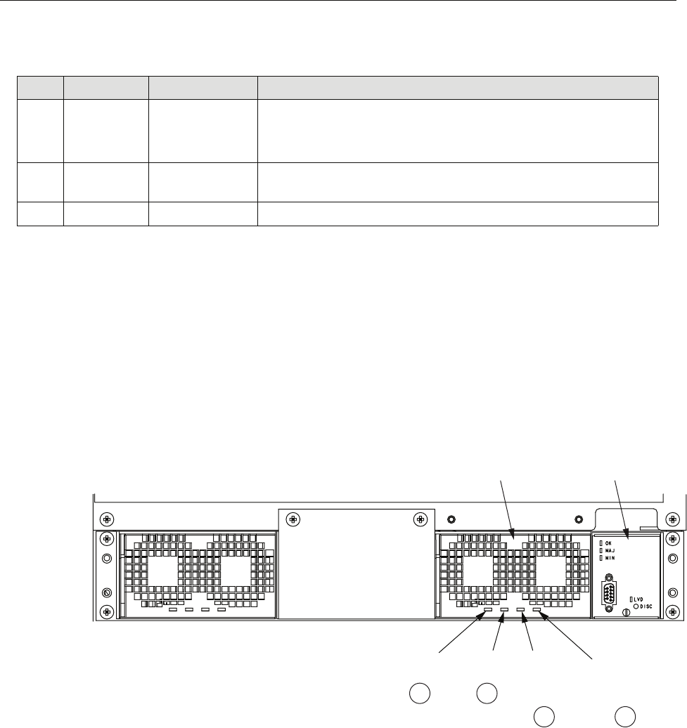
1.8 Rectifier Shelf
The Rectifier Shelf, shown in Figure 18, is a chassis/backplane device that contains rectifier
modules and a Low Voltage Disconnect (LVD) unit. The shelf interconnects the rectifier
modules and LVD unit, and provides an interface to external connectors.
Typically, the rectifier shelf contains two rectifier modules. The center panel on the shelf can be
removed to add a third rectifier, providing N+ redundancy as more equipment is added to the
RAN chassis.
Figure 18. Rectifier Shelf
1.8.1 Rectifier Module
The rectifier module converts 240 VAC prime power into -48 VDC for use within the RAN.
Each rectifier has four LEDs, shown in Figure 18 and described in Table 12. The rectifiers are
controlled by the LVD unit under command of the STF2 module.
4D OUT SMA connectors Diversity Out. 6 diversity outputs (bands A-F); each output being
used connects on one RDC module, in either same RAN or extension
RAN if present. Connection is made using cable 1955000P081
5FLT Red LED Fault. Lights when module has failed and during start-up until mod-
ule has initialized
6PWR Green LED Power. Lights when module has power
Table 11. P/MCPLR Modules Faceplate Components
REF # DESIGNATION DEVICE FUNCTIONAL DESCRIPTION
21319-A
21
34
OVER
VOLTAGE
PROTECTION
LED
DC OK
LED
AC OK
LED
OVER
TEMPERATURE
PROTECTION
LED
RECTIFIER
LOW VOLTAGE
DISCONNECT
(LVD) UNIT
ADCP-75-210 • Issue 1 • March 2007
Page 24
© 2007, ADC Telecommunications, Inc.
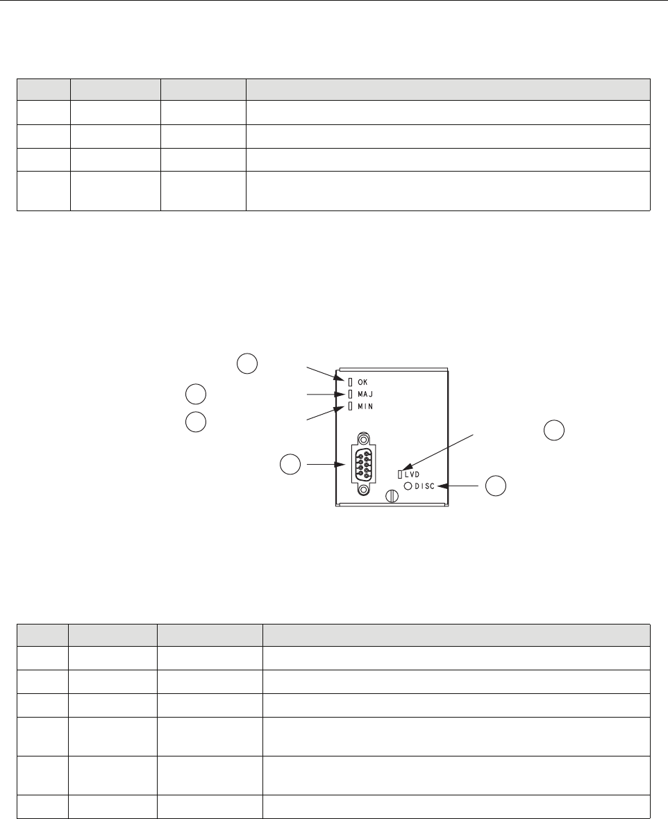
1.8.2 Low Voltage Disconnect (LVD) Unit
The Low Voltage Disconnect (LVD) Unit (Figure 19) disconnects power automatically when
the RAN voltage falls below a specified minimum. The LVD unit also manages the backup
batteries (extended or glitch).
Figure 19. Low Voltage Disconnect Unit
Table 12. Rectifier Indicators
REF # DESIGNATION DEVICE FUNCTIONAL DESCRIPTION
1(Unmarked) Green LED AC OK. Lights when AC power is present
2(Unmarked) Green LED DC OK. Lights when rectifier is limiting current
3(Unmarked) Red LED Over Voltage Protection. Lights when rectifier has failed
4(Unmarked) Red LED Over Temperature Protection. Lights when over temperature compen-
sation circuit is active
Table 13. LVD Indicators
REF # DESIGNATION DEVICE FUNCTIONAL DESCRIPTION
1OK Green LED Okay. Lights when power system is functioning correctly
2MAJ Red LED Major Fault. Lights when a major fault exists
3MIN Yellow LED Minor Fault. Lights when a minor fault exists
4(Unmarked) 9-pin connector Connector for cable 1001476P001 to the RECT (RJ45 connector)
port on the STF module
5LVD Red LED Low Voltage Disconnect. Lights when switch has closed due to low
voltage
6DISC Switch Disconnect. Pressing this switch disconnects the backup batteries
1
2
3
4
6
5
OK LED
MAJOR FAULT LED
MINOR FAULT LED LVD ON LED
21334-A
ADCP-75-210 • Issue 1 • March 2007
Page 25
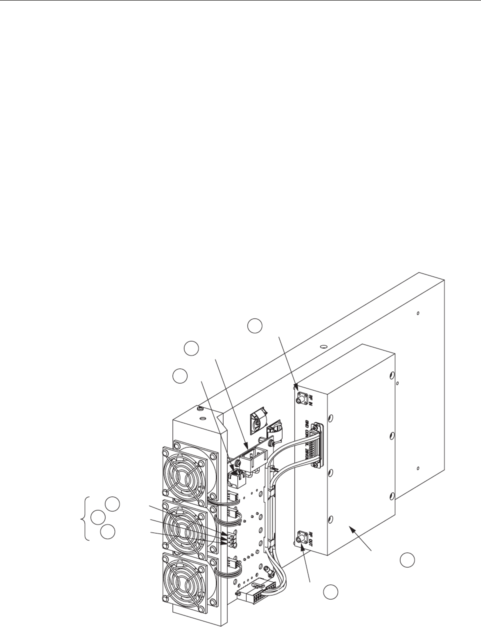
1.9 Power Amplifier Assembly
The Power Amplifier Assembly (PAA) is an electronic device that amplifies RF signals in the
forward path just before they are transmitted to the RAN antenna. Up to four PAAs may be
mounted in the RAN, each providing one band. Each PAA consists of a Power Amplifier (PA), a
control board called the PA Interface Controller (PIC), and a cooling system. The PA is multi-
channel. Different units are used for PCS, Cellular, and SMR 800 bands.
The PIC interfaces to the discrete signals of the PA. The PIC also provides DC power to the PA
by converting from -48 VDC to +12 VDC or +28 VDC depending upon which PA is being used.
Each PA has its own PIC. The PIC is managed is managed by the CPU over an I2C connection
through its corresponding RUC. The cooling system consists of a heat sink and three fans that
provide cooling for the PA by blowing external air across the heat sink. The fans are software-
controlled. The PIC module monitors the tachometer outputs of the fan.
Figure 20 shows the PA assembly connection points and indicators. Table 14 describes the items
called out in the figure.
Figure 20. Power Amplifier Assembly
DC_ IN
DC_ OUT
DC_ FAULT
PIC LED
INDICATORS
12C
48V
PWR
RF
OUT
POWER
AMPLIFIER
21276-A
5
RF IN
8
4
7
6
1
2
3

ADCP-75-210 • Issue 1 • March 2007
Page 26
© 2007, ADC Telecommunications, Inc.
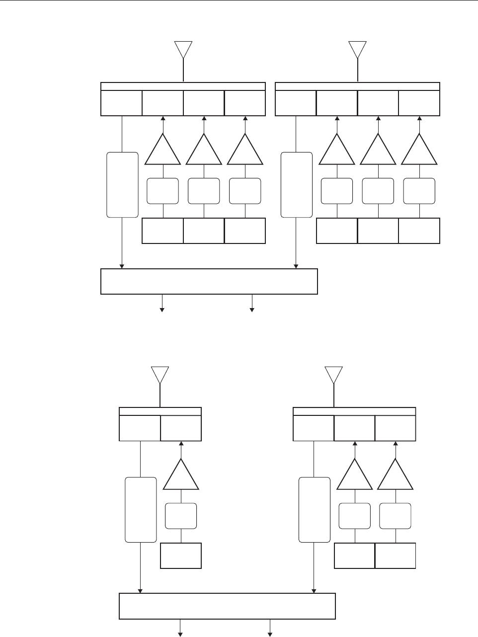
1.10 Multiplexer System
The NXD RAN multiplexer system consists of four units that interface to the antenna, PAs, and
multicouplers:
• Quadplexer Primary (PCS Bands A, B, F), interfaces to PCS primary antenna;
• Quadplexer Diversity (PCS Bands D, E, C), interfaces to PCS diversity antenna;
• Triplexer Primary, either of two types:
– Type one (Cellular Band B, SMR800 Band), interfaces to 800 MHz primary antenna;
– Type two (SMR800 Band, SMR900 Band), interfaces to 800 MHz primary antenna;
• Diplexer Diversity (Cellular Band A), interfaces to 800 MHz diversity antenna.
For a schematic of the PCS multiplexers, see Figure 21. For a schematic of the Cellular/SMR
multiplexers, see Figure 22 (showing Cellular B, SMR800 triplexer) or Figure 23 (showing
SMR800, SMR900 triplexer).
Table 14. PAA Connection Points and Indicators
REF # DESIGNATION DEVICE FUNCTIONAL DESCRIPTION
1DC_IN Green LED DC In. Lighted when PIC has -48 VDC input
2PA_FAULT Red LED PA Fault. Lighted when PA has failed
3DC_OUT Green LED DC Out. Lighted when PIC has +28 VDC output
4I2C RJ-45 connector
(J1)
I2C (Bus). Connection to RUC module P/A CNTRL using
cable 1001475P001
548V PWR Positronic 3-pin
connector (J2)
48 Volt DC Power. Input to PIC for -48 VDC using PIC
power harness 1001471P001
6RF OUT SMA connector RF Out. Output of PA for cable 1955000P080 to one of the
four plexers (depending on band), connector port TX
7(Unmarked) Power Amplifier Power amplifier (see description on preceding page)
8RF IN SMA connector RF In. Input from RUC for cable 19559999P079
ADCP-75-210 • Issue 1 • March 2007
Page 27
© 2007, ADC Telecommunications, Inc.
Figure 21. PCS Multiplexers
Figure 22. Cell/SMR Multiplexers (With Cell/SMR 800 Triplexer)
RUC
Tx
A
MCPA
RUC
Tx
B
MCPA
RUC
Rx
1850-1910
Tx
1950-1965
Tx
1930-1945
Tx
1970-1975
Tx
F
MCPA
Primary
Antenna
Diversity
Antenna
Quadplexer
PCS Band
A/B/F
Quadplexer
PCS Band
D/E/C
Rx
A
B
C
D
E
F
Primary
RUC
Tx
D
MCPA
RUC
Tx
E
MCPA
RUC
Rx
1850-1910
Tx
1965-1970
Tx
1945-1950
Tx
1975-1990
Tx
C
MCPA
Rx
A
B
C
D
E
F
Diversity
Antenna Assembly
Multicoupler
1850/1910
21270-A
RUC
Tx
A” A
MCPA
Rx
810-849
Tx
869-880
Primary
Antenna
Duplexer
800 Mhz Band
Rx
SMR
A”
A
B
B’
Antenna Assembly
Multicoupler
810-849 21271-B
RUC
Tx
SMR-A
MCPA
Rx
810-849
Tx
855-866
RUC
Tx
B B’
MCPA
Tx
880-894
Diversity
Antenna
Triplexer
800 Mhz Band
Rx
SMR
A
CELL
A”
A
B
ADCP-75-210 • Issue 1 • March 2007
Page 28
© 2007, ADC Telecommunications, Inc.
Figure 23. SMR Multiplexers (With SMR 800/900 Triplexer)
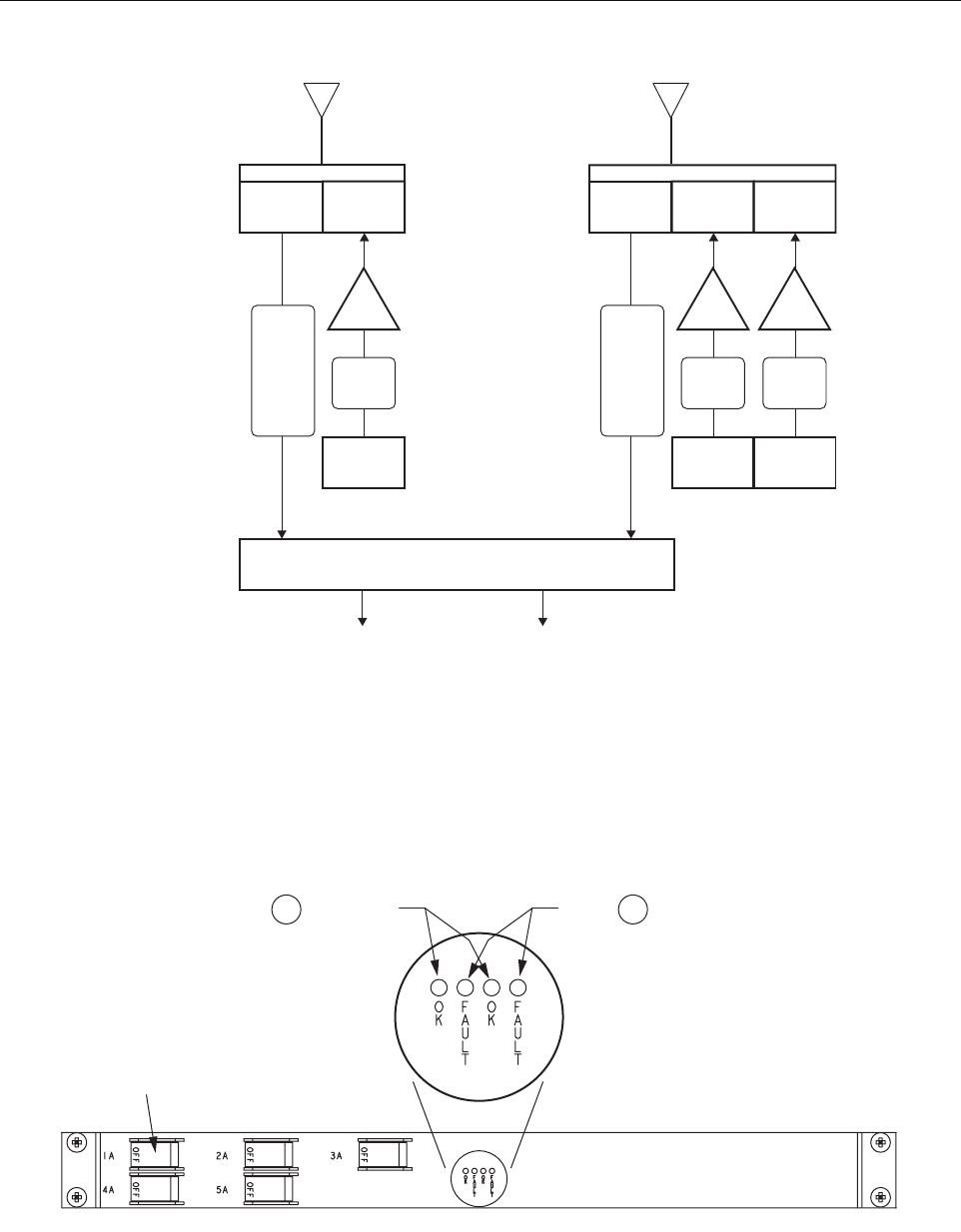
1.11 Circuit Breaker Panel
The Circuit Breaker Panel, shown in Figure 24, contains five circuit breakers. It distributes the
RAN’s -48 VDC power and protects the RAN’s electronics. Table 15 gives the circuit breaker
functions. Table 16 describes the panel LEDs.
Figure 24. Circuit Breaker Panel
RUC
Tx
A” A
MCPA
Rx
810-849
Tx
869-880
Primary
Antenna
Duplexer
800 Mhz Band
Rx
SMR A
A”
A
Antenna Assembly
Multicoupler
810-901 21779-A
RUC
Tx
SMR-A
MCPA
Rx
810-901
Tx
851-869
RUC
Tx
SMR-B
MCPA
Tx
935-940
Diversity
Antenna
Triplexer
800 Mhz Band
Rx
SMR A
SMR B
A”
A
21320-A
12
SYSTEM OK
LEDs
FAULT
LEDs
CIRCUIT
BREAKER
(5 PLACES)

ADCP-75-210 • Issue 1 • March 2007
Page 29
© 2007, ADC Telecommunications, Inc.
1.12 Backup Batteries
The NXD RAN has two backup battery options:
• Extended Batteries: provide backup protection for up to two hours. These are four 12V,
85-100 AH internal batteries connected in series for a -48V system. The four batteries
together with associated wiring and hardware weigh 325 pounds (147.7 kg).
• Glitch Batteries: provide backup protection for up to five minutes. These are small,
motorcycle type batteries connected in a series configuration.
1.13 Antenna
ADC provides a pole-mount antenna kit for use when the RAN is mounted on a wooden utility
pole. The kit must be separately ordered from the RAN. Pole mounting is the most common
type of RAN installation.
The antenna offered interfaces with the PCS and Cellular/SMR bands and supports two branch
diversity receive paths. Also included in the kit is the GPS antenna used by the RAN.
The RAN may also be mounted outdoors on a concrete pad. This type of installation may use a
conventional directional antenna in either a sector or quasi-omni antenna configuration,
depending on the coverage objective and design. Proper antenna selection and the mounting
installation are the responsibility of the design engineer.
Antenna installation is covered in separate publications, available for downloading from the
ADC web site, www.adc.com. Refer to RELATED PUBLICATIONS on Page vii.
Table 15. Circuit Breaker Functions
BREAKER FUNCTION
1A PA1
2A PA2
3A PA3
4A PA4
5A cPCI chassis
Table 16. Circuit Breaker Panel LEDs
REF # DESIGNATION DEVICE FUNCTIONAL DESCRIPTION
1OK Green LED Okay. Lights when AC power is present
2FAULT Red LED Fault. Lights when rectifier is limiting current

ADCP-75-210 • Issue 1 • March 2007
Page 30
© 2007, ADC Telecommunications, Inc.
2 STANDARD INSTALLATION PROCEDURES
This section provides the standard procedures for a typical installation. The RAN may be
installed either on a wooden pole or on a concrete pad.
This section is organized as follows:
• Sections 2-1 through 2-4 provide information that is relevant before installing the cabinet.
These subsections contain an installation overview, unpacking instructions, a list of
required material and tools, and site preparation guidelines.
• Section 2-5 tells how to install a cabinet on a wooden utility pole. Included are instructions
for installing the pole mount bracket and then installing the cabinet on the bracket. Also
included are instructions for installing the rain shields.
• Section 2-6 tells how to install the RAN on a concrete pad. Included are instructions for
pouring the concrete pad, mounting the RAN on the pad, and installing the pedestal
enclosure.
• Section 2-7 contains other standard procedures typically done at every installation. These
procedures describe how to install the solar shield, grounding wire, RF cables, fiber optic
cable, AC power, and backup batteries.
Installation of the RAN cabinet may proceed separately from the installation of the
corresponding Hub equipment. When the installation of the RAN is completed, refer to the
Digivance NXD Multi-Band Distributed Antenna System Operation Manual (ADCP-75-209)
for system turn-up and test procedures.
The procedures in this section assume that the required Outside Plant (OSP) fiber optic cable
has already been routed between the Hub and the RAN, that the required antenna has been
installed, and that a coaxial cable terminated with an N-type connector has been routed to the
RAN from the antenna.
2.1 Installation Overview
A standard (typical) installation of the RAN consists of the following steps:
Note: Section 3 contains instructions for installing a second RAN at the same location.
Section 4 provides information on non-standard installation procedures such as installing
an electronic module.
Danger: Wet conditions increase the potential for receiving an electrical shock when installing
or using electrically-powered equipment. To prevent electrical shock, never install or use
electrical equipment in a wet location or during a lightning storm.
Caution: Always allow sufficient fiber length to permit routing of patch cords and pigtails
without severe bends. Some fiber optic patch cords or pigtails may be permanently damaged if
bent or curved to a radius of less than 2 inches (50 mm).
Warning: Electronic components can be damaged by static electrical discharge. To prevent
ESD damage, always wear an ESD wrist strap when handling electronic components.

ADCP-75-210 • Issue 1 • March 2007
Page 31
© 2007, ADC Telecommunications, Inc.
1. Checking out and preparing the installation site.
2. Unpacking and inspecting the shipped items.
3. Installing a pole mount frame or pedestal mount.
4. Installing the RAN cabinet on the pole or pad.
5. Installing the rain shields (pole mount) or pedestal enclosure (pad mount).
6. Installing the solar shield.
7. Installing a ground wire.
8. Connecting RF cables between the antenna and RAN.
9. Installing the fiber optical cable that connects the RAN to the Hub.
10. Installing AC power.
11. Installing backup batteries in the cabinet.
2.2 Unpacking and Inspection
The RAN is shipped to the field pre-configured with all modules and components that the
customer has ordered. Electronic modules except for the batteries are shipped already installed
in the cabinet.
The following optional accessories may also be shipped with the RAN:
• Back-up batteries
• Non-standard SFP optical transceiver
Use the following procedure to unpack and inspect the RAN components:
1. Open the shipping cartons and carefully unpack each component from the protective
packing material.
2. Check each component for broken or missing parts. If there are damages, contact ADC for
an RMA (Return Material Authorization) and to reorder if replacement is required. For
contact information, refer to Section 6 on Page 72.
2.3 Required Materials and Tools
The following materials must be supplied by the installer:
• (Pole mount only) Three galvanized steel square headed bolts with minimum tensile
strength of 20,050 lbs., 3/4 in. diameter, and of a length appropriate to pole diameter;
Three nuts for bolts, three flat washers, three split ring washers, and three 3-in. square
curved washers (see Figure 27 on Page 39)
Note: To insure that all optical connectors and optical ports remain dust-free during
installation, leave all dust caps and dust protectors in place until directed to remove them
for installation.

ADCP-75-210 • Issue 1 • March 2007
Page 32
© 2007, ADC Telecommunications, Inc.
• (Pad mount only) Four 1/2 in. diameter galvanized steel bolts with four lock washers, four
flat washers, and four concrete anchors (see Figure 29 on Page 41)
• 3M 8426-9M cold shrink
• 3M Skothkote Electrical Coating 14853
• Ten Type N plugs (CommScope PN: 540ANM or equivalent)
• Coaxial cable (CommScope PN: FXL540OPE or equivalent)
• Electrician’s tape
• Water seal
• Electrical conduit
• Conduit fittings
• Connector sealant material
• Panduit LLCF6-14B-L or equivalent (X2)
• Two-hole compression lug terminal for #6 AWG wire
• Ground rod
• Connector for attaching #6 AWG grounding wire to approved ground source
The following tools are required to perform this procedure:
• Torque wrench
• Drill
• Drill bit (appropriate for pole width and 3/4 in. bolts)
• 7/16 in. open-end wrench
• Compression pliers for #6 AWG grounding lug
• Wire cutters
• Wire strippers
• Conduit cutter
• Conduit bender
2.4 Site Preparation
This section describes site preparation for installation and is presented only as a guideline for a
typical RAN installation.
2.4.1 Space Requirements
When an installation site for the RAN is selected, either on a utility pole or concrete pad, care
must be exercised to ensure that the site provides adequate space and clearance to accommodate
the current installation and any future upgrades. Table 17 gives RAN dimensions.

ADCP-75-210 • Issue 1 • March 2007
Page 33
© 2007, ADC Telecommunications, Inc.
2.4.2 Power Requirements
Power must be available at the RAN site. The RAN requires 240 VAC, single phase, 20 Amps
service. Included with the power meter must be surge protection and circuit breakers.
The RAN can have up to three 1500 watt rectifiers. For the minimum specified voltage (176
VAC), each can draw up to 10 amps. The RAN will draw up to 1800 watts normally, but when
batteries are re-charging that amount will increase the current draw into a RAN to up to 16
Amps. Therefore, one 20 Amps service is required per four band RAN.
In a pole mount installation, the power meter is typically installed on the pole below the unit in
separate boxes. In a concrete pad installation, an external junction box is typically placed near
the RAN providing AC power, surge protection, and circuit breakers.
2.4.3 Antenna Requirement
ADC offers a pole-mount antenna kit (accessory) for use when the RAN is mounted on a
wooden utility pole. Either a 2 in. (5.08 cm) O.D. model or a 9 in. (22.86 cm) O.D. model can
be ordered. Pole mounting is the most common installation. The antenna interfaces with the
PCS and Cellular/SMR bands and supports two branch diversity receive paths. Also included in
the kit is the GPS antenna used by the RAN. Installation instructions for the pole mount antenna
are included with the kit.
When the RAN is mounted on a concrete pad, a conventional directional antenna may be used
(customer supplied). The antenna may be set to operate in either a sector or quasi-omni
configuration, depending on the coverage objective and design. Proper antenna selection and the
mounting installation are the responsibility of the design engineer.
2.4.4 RF Cable Requirements
RF cables are required at the installation site to provide the physical link between the RAN and
the antenna. In a pole-mount installation, U-duct of an appropriate size is also required to cover
the RF cables on the pole. The U-duct provides only physical protection. It should not be
considered to provide electrical isolation from conductors on the pole. Adequate clearance must
be obtained for the routing of these cables past the existing services as defined in the previous
topic. In a concrete pad installation, RF cables from the antenna are routed and protected per the
installation plan provided by the design engineer.
Table 17. RAN Dimensions
CONFIGURATION WIDTH HEIGHT DEPTH
RAN 31.35 in. (76.7 cm) 36.5 in. (92.7 cm) 27.5 in. (69.9 cm)
Dual RAN 31.25 in. (76.7 cm) 73 in. (185.4 cm) 27.5 in. (69.9 cm)

ADCP-75-210 • Issue 1 • March 2007
Page 34
© 2007, ADC Telecommunications, Inc.
2.4.5 Fiber Requirements
Optical fibers are required at the site to provide the physical link between the RAN and the Hub.
In a typical installation, the identified fibers are broken out of a multi-fiber sheath and routed to
a splice box where they are spliced to pigtails connecting the main sheath to the RAN. The
actual fiber bundle location on the utility pole may vary per the agreed to attachment point.
Refer to Figure 25. The nylon cable connector on the rear of the RAN accommodates cables of
a diameter in the range .38 to .50 inches (.97 to 1.27 cm). For larger size cables, refer to
Section 1.6.2 on Page 9.
2.5 Installing a RAN Cabinet on a Wooden Utility Pole
Figure 25 shows the main components and their spatial placement in a typical NXD RAN pole
mount installation.
2.5.1 Site Requirements Unique to Pole Mounting Locations
If power lines are present at the top of the pole, spacing requirements applicable to the RF
cabling and any other hardware installed in the electric space must be considered. Per the
National Electrical Safety Code, vertical clearance at supports for primary-supply conductors
above other facilities is required to be 16 in. (40.64 cm) above neutrals and 40 in. (101.6 cm)
above communications (60 in. [152.4 cm] if above 8700V).
For supply conductors at voltages up to 8700 between conductors, the minimum horizontal
clearance provided by the NESC ANSI C2 is 12 in. (30.5 cm). For higher voltages, it is required
that .4 in. (10.2 mm) be added for every 1000V above 8700. Table 18 lists the required
clearances for some common high voltages.
This information is from the Standard Handbook for Electrical Engineers, 13th Edition,
McGraw Hill, Chapter 18, Section 151, Pages 18-65.
Table 18. Antenna Clearance vs. Voltage
VOLTAGE HORIZONTAL CLEARANCE
8700V 12.0 in. (30.5 cm)
15 kV 14.52 in. (36.9 cm)
28 kV 19.72 in. (50.1 cm)
38 kV 23.72 in. (60.2 cm)
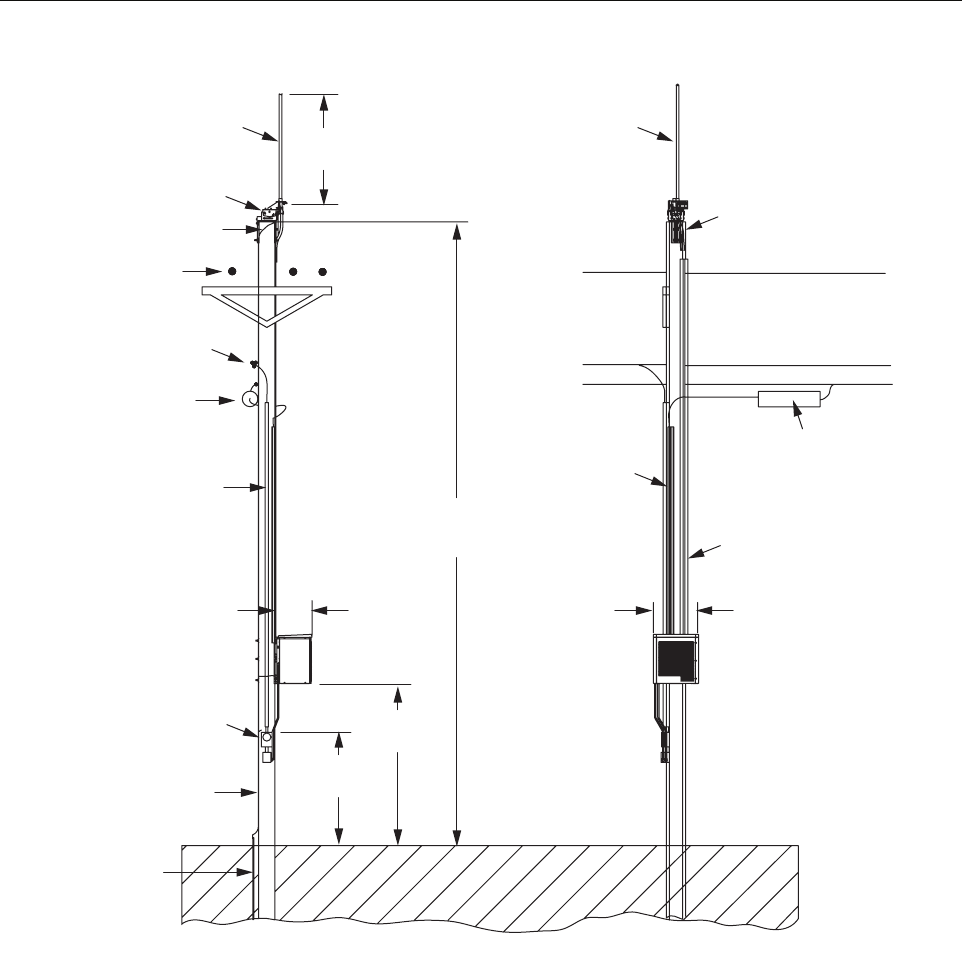
ADCP-75-210 • Issue 1 • March 2007
Page 35
© 2007, ADC Telecommunications, Inc.
Figure 25. Typical Pole-Mount Installation
2.5.2 Pole Loading Analysis
A pole loading analysis should be performed before the RAN is mounted on the pole to verify
that the pole can support the weight of the RAN in various conditions. The analysis should take
into account the pole top antenna, the RAN and batteries, and the possibility of an expansion
RAN with batteries. Table 19 lists the weights of various NXD components and configurations.
21285-A
ANTENNA ANTENNA
ANTENNA
MOUNTING
BRACKET
100 IN.
(254 CM)
GROUND WIRE
TO ANTENNA
PRIMARY
POWER
PRIMARY POWER
SECONDARY POWER LINE
SECONDARY
POWER
FIBER
FIBER SPLICE CAN
FIBER OPTIC LINE
2 IN. SCHEDULE 40
CONDUIT FOR POWER IN
CARLTON PT. NO.
49011-010 OR
EQUIVALENT
SIDE
VIEW
FRONT
VIEW
27.5 IN.
(69.85 CM)
31.25 IN.
(79.4 CM)
7 FT. (2.1 M)
TYPICAL
JUNCTION
BOX
#6 AWG COPPER
GROUND WIRE TO
METER BOX, RAN,
AND ANTENNA
10 FT. (3 M)
TYPICAL
38.6 FT.
(11.8 M)
TYPICAL
1.5 IN. SCHEDULE 40
POLE RISER FOR
FIBER OPTIC LINES
CARLTON PT. NO.
59010N OR
EQUIVALENT
3 IN. SCHEDULE 40
CONDUIT FOR
RF CABLES
CARLTON PT. NO.
49013-010 OR
EQUIVALENT
RF CABLES
TO RAN
(5 REQUIRED)
COPPER
GROUND
ROD
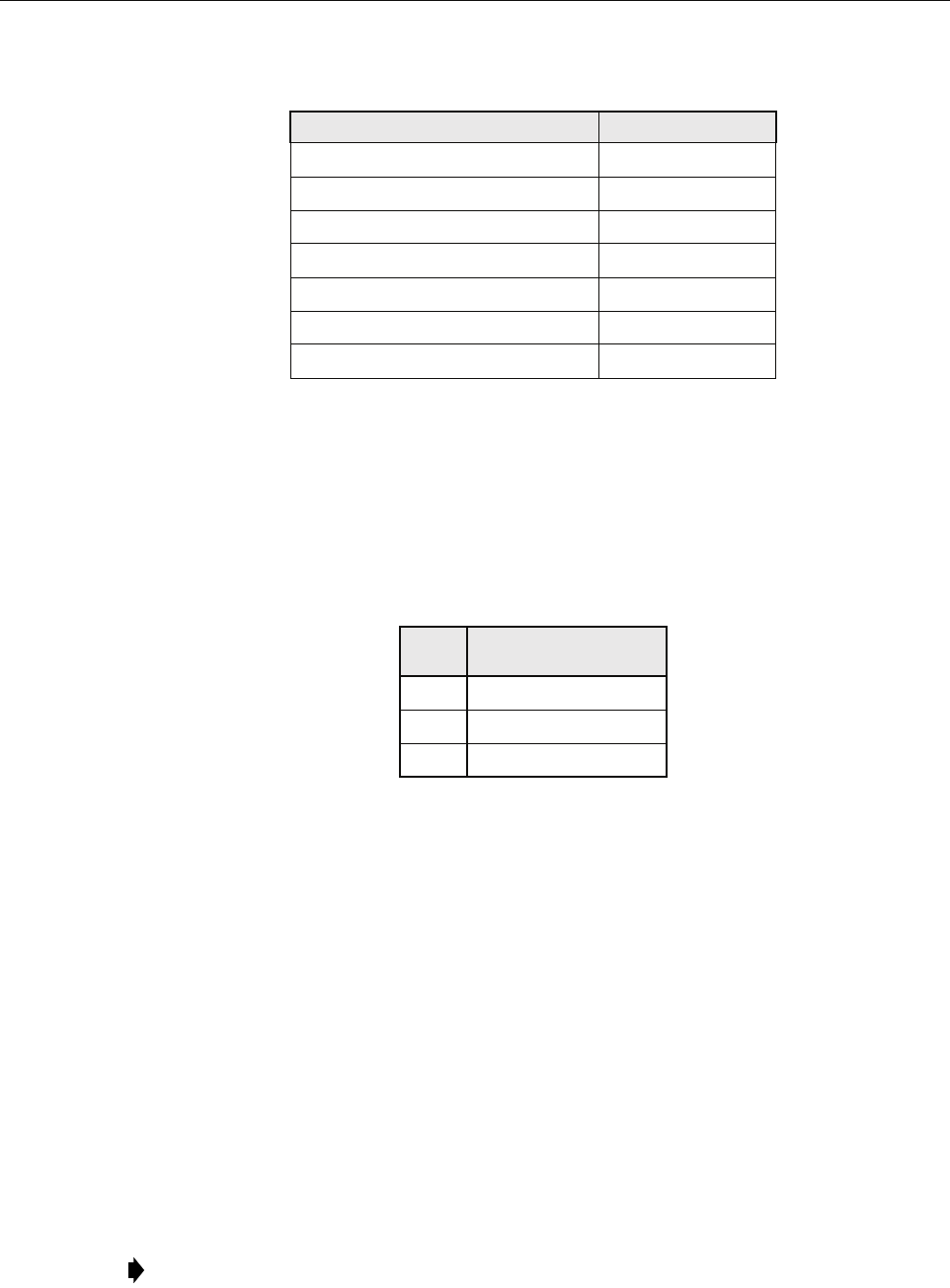
ADCP-75-210 • Issue 1 • March 2007
Page 36
© 2007, ADC Telecommunications, Inc.
Three load types should be considered: static weight loading, ice loading, and wind loading.
These types should be considered on the pole, wires, and any equipment installed on the pole.
A qualified engineer should perform the pole loading analysis, taking into account both vertical
and horizontal forces. The specified horizontal load is applied 2 ft. (60.1 cm) from the top and
the assumption is that the pole acts as a cantilever with maximum stresses applied at the ground
level. Table 20 provides acceptable loads by pole class.
The strength of the wood pole is defined in Standard Handbook for Electrical Engineers, 13th
Edition, McGraw Hill, Chapter 18, Section 135, “Strength of Wood Poles,” Pages 18-57. The
wood pole strength calculation is defined in Standard Handbook for Electrical Engineers, 13th
Edition, McGraw Hill, Chapter 18, Section 136, Reference NEC.
2.5.3 Installing the Cabinet Mounting Bracket
The Digivance NXD Wood Pole Mounting Bracket, shown in Figure 26, is an accessory item
that is used to attach the Digivance NXD cabinet to a power distribution pole or related object.
The bracket is attached to the pole using galvanized steel square head bolts that are attached
through holes drilled through the wooden pole. An example of an installed NXD wood pole
mounting bracket is shown in Figure 26.
Use the following procedure to install the RAN wood pole mounting bracket:
1. Determine the mounting height of the RAN and mark the pole at the desired location of
the base of the RAN.
Table 19. RAN Component Weights
CONFIGURATION OR COMPONENT WEIGHT
Base RAN without batteries 379 lbs. (172.3 kg)
Base RAN with four batteries 679 lbs. (308.6 kg)
Expansion RAN with four batteries 619 lbs. (281.4 kg)
Antenna pole-mount bracket (9 inch) 56 lbs. (25.5 kg)
Antenna pole-mount bracket (2 inch) 57 lbs. (25.9 kg)
Pole-top antenna (9 inch) 47 lbs. (21.4 kg)
Pole-top antenna (2 inch) 12 lbs. (5.5 kg)
Table 20. Loading by Pole Class
POLE
CLASS HORIZONTAL LOAD
1 5400 lbs. (2454.5 kg)
2 3700 lbs. (1681.8 kg)
3 3000 lbs. (1363.6 kg)
Note: Install the RAN pole mount bracket on the side of the utility pole assigned by the
utility company or required by local zoning.
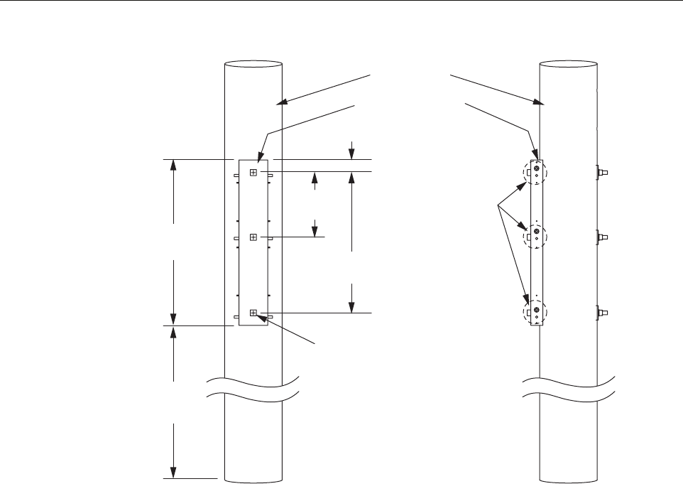
ADCP-75-210 • Issue 1 • March 2007
Page 37
© 2007, ADC Telecommunications, Inc.
Figure 26. Cabinet Mounting Bracket
2. Place the pole mount bracket against the pole.
3. Strap or otherwise hold the bracket in place.
4. Using a level, adjust the bracket to make it vertically level.
5. Mark the three holes to be drilled through the wood pole.
6. Remove the pole mount bracket.
7. Drill three holes through the pole using a 7/8 in. wood bit.
8. Using a 3/4 in. machine bolt, put a 2 in. flat washer on the bolt.
9. Place the pole mounting bracket against the pole.
10. Align the holes in the bracket with the holes drilled in the pole.
11. Install one bolt through the bracket and pole (using any of the three holes).
12. Place a 3 in. square curved washer, lock washer, and 3/4 in. nut on the other end of the
machine bolt; do not tighten.
13. Repeat steps 8-12 for the other two holes.
14. Using a 1-1/8 in. wrench, tighten the mounting hardware to 103 ft.-lbs.
21286-A
UTILITY POLE
MOUNTING BRACKET
34.5 IN.
(87.6 CM)
13.5 IN.
(34.3 CM)
29.25 IN.
(74.3 CM)
2.63 IN.
(6.7 CM)
10 FT.
(3 M)
TYPICAL
RAN
ATTACH MENT
POINTS
HOT DIPPED GALVANIZED MACHINE
BOLT SQUARE HEAD 3/4 x 16.00 LG
W/NUT (J9816) 3 REQUIRED
ROUND FLAT WASHER 2.00 O.D.
(J1089) 3 REQUIRED
SQUARE CURVED WASHER
3 x 3 x 1/4 (J6823) 3 REQUIRED
SPRING LOCK WASHER
.234 x.188 (J140) 3 REQUIRED
OR EQUIVALENT

ADCP-75-210 • Issue 1 • March 2007
Page 38
© 2007, ADC Telecommunications, Inc.
2.5.4 Mounting the RAN Cabinet on the Bracket
The cabinet is shipped with the mounting hardware required for mounting the RAN cabinet on
the RAN wood pole mounting bracket. The hardware consists of six 1/2 in. bolts, six nuts, 12
lock washers, and 12 flat washers. Use the following procedure to mount the cabinet. Refer to
Figure 27.
1. Remove the RAN from the mounting pallet.
2. Securely attach the boom truck cable to the four hoist eyes of the RAN.
3. Carefully raise the RAN toward the cabinet mounting bracket.
4. With a person in the bucket truck and positioned at the RAN pole mounting bracket, guide
the RAN onto the RAN pole mounting bracket so that the RAN holds onto the studs on the
mounting bracket.
5. Place a lock washer and a flat washer on a 1/2 in. by 1-3/4 in. bolt.
6. Screw the bolt in hand tight.
7. Repeat the previous two steps for the remaining five mounting holes.
8. Install a flat washer, lock washer, and nut on each of the six studs.
9. Using a 3/4 in. wrench, tighten the bolts to 75 ft.-lbs.
10. Carefully detach the boom truck cable from the hoist eye of the RAN.
11. Remove the hoist eyes by unscrewing from the RAN top.
2.5.5 Installing the Rain Shields
There are two rain shields to be installed on the rear of the RAN. They are identified as “rain
shield right” and “rain shield left.” Use the following procedure to install the rain shields. Refer
to Figure 27.
1. Using the supplied hardware, place the left rain shield over the three studs in the pole
mount bracket and three studs on the RAN.
2. Place a lock washer then a nut on each stud.
3. Using a nut driver or wrench, tighten to 6 ft.-lbs.
Caution: Do not install batteries in the RAN prior to mounting the RAN securely on the utility
pole.
Note: Once the RAN is hung on the studs, the through bolts will self-align.
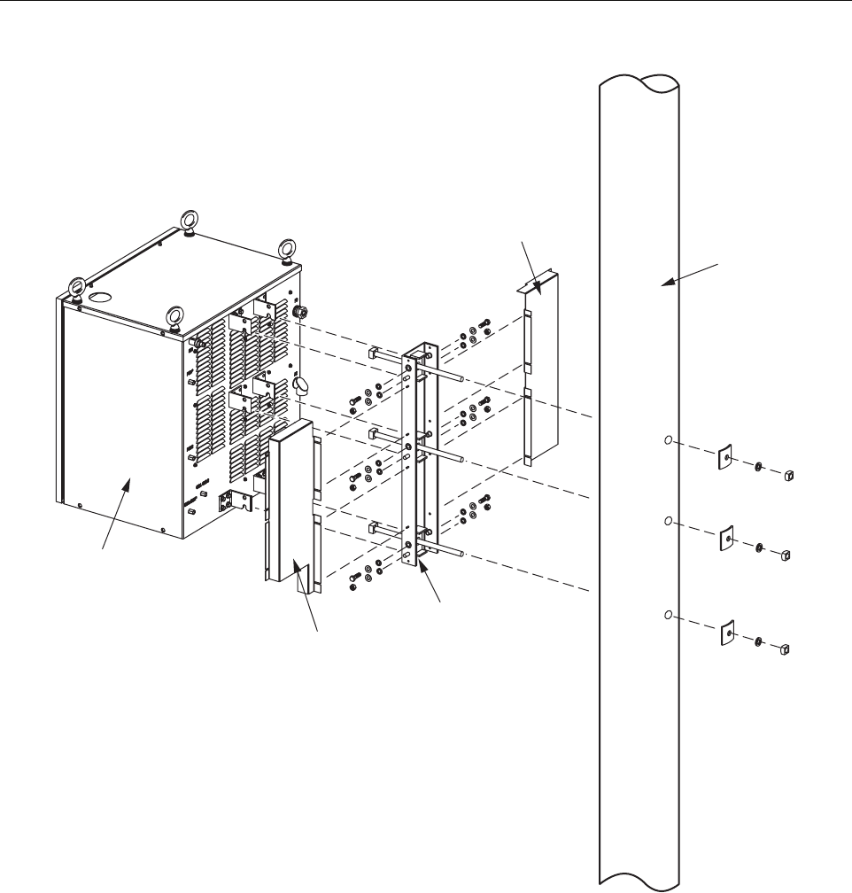
ADCP-75-210 • Issue 1 • March 2007
Page 39
© 2007, ADC Telecommunications, Inc.
Figure 27. Pole Mount Components
2.6 Installing a RAN Cabinet on a Concrete Pad
This section contains the procedures for installing the RAN on a concrete pad.
Choose an installation site that conforms to all local codes. Obtain all required permits prior to
starting installation. Situate the concrete pad along the trench that was used for routing the OSP
fiber cables for the system.
RAN
CABINET
POLE MOUNT
BRACKET
RAIN
SHIELD
LEFT
RAIN
SHIELD
RIGHT
UTILITY
POLE
21345-A
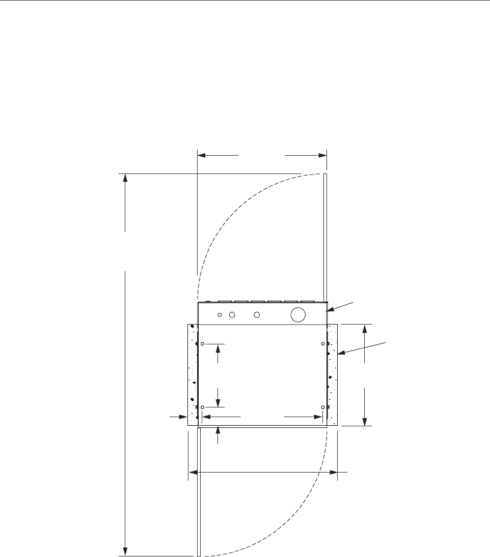
ADCP-75-210 • Issue 1 • March 2007
Page 40
© 2007, ADC Telecommunications, Inc.
2.6.1 Pouring a Concrete Pad
Prepare a base for the concrete pad that meets all local code requirements. The base must have a
footing of 4 to 6 inches (10.2 to 15.2 cm) of sand or gravel on firmly compacted soil. Concrete
pad height is site and climate dependent. Height should be based on keeping the front door air
intake louvers and rear bottom exhaust vent free of obstruction. For dimensions of pad, refer to
Figure 28.
Figure 28. Concrete Pad Dimensions
2.6.2 Mounting the Cabinet on a Concrete Pad
Use the following procedure to mount the cabinet on the concrete pad.
1. Fasten the pedestal mounts to the concrete pad using the customer-supplied hardware
identified in Figure 29.
15.38 IN.
(39.07 CM)
4.3 IN.
(10.9 CM)
29.00 IN.
(73.66 CM)
HOLES FOR
PEDESTAL
MOUNT
24.0 IN.
(61 CM)
3.5 IN.
(8.9 CM)
36.0 IN.
(91 CM)
31.0 IN.
(79 CM)
CONCRETE PAD
(MINIMUM SIZE)
RAN CABINET/
PEDESTAL ENCLOSURE
FOOT PRINT
DOOR
CLEARANCE
92.0 IN.
(234 CM)
21308-A
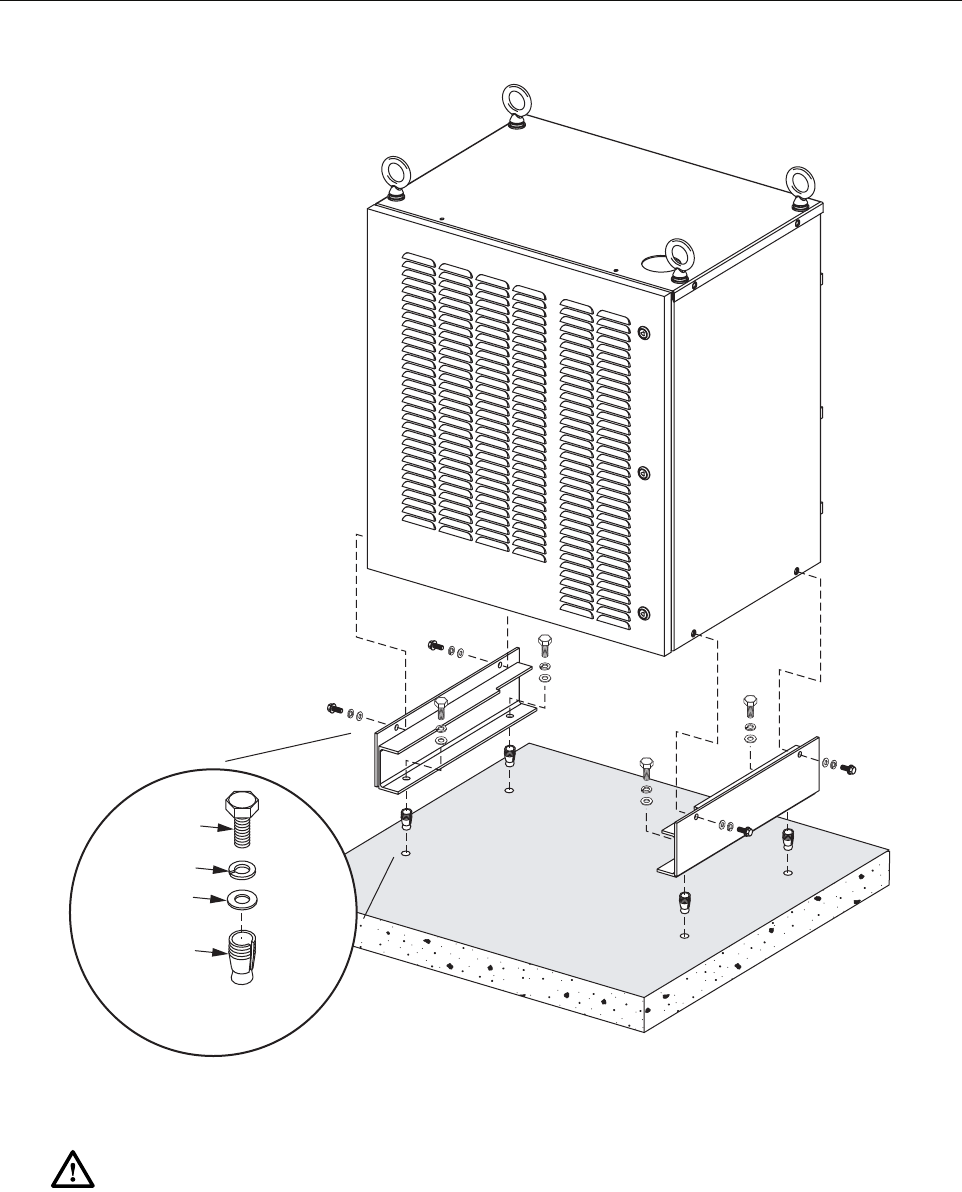
ADCP-75-210 • Issue 1 • March 2007
Page 41
© 2007, ADC Telecommunications, Inc.
Figure 29. Installing Pedestal Mount and Cabinet
2. Using appropriate lifting equipment, lower the cabinet into position on the cabinet mounts.
3. Secure the cabinet from the side, as shown, using the four bolts, four flat washers, and four
lock washers from the shipping pallet mounting brackets.
Warning: Use appropriate lifting equipment when moving or installing the cabinet. Do not
stand under the cabinet as it is being hoisted into position for installation. A failure of the lifting
equipment could result in serious personal injury.
21306-A
1/2 x 13
BOLT
CONCRETE
ANCHOR
LOCK
WASHER
FLAT
WASHER
TYPICAL CUSTOMER
SUPPLIED HARDWARE
(4 PLACES)
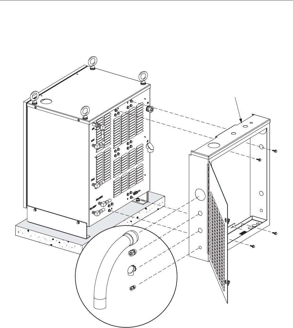
ADCP-75-210 • Issue 1 • March 2007
Page 42
© 2007, ADC Telecommunications, Inc.
2.6.3 Installing the Pedestal Enclosure
The pedestal enclosure, shown in Figure 30, mounts on the back of the cabinet.
Figure 30. Installing Pedestal Enclosure
Use the following procedure to install the pedestal enclosure:
1. Orient the pedestal enclosure as shown and attach it to the back of the cabinet using the
four bolts provided.
2. Close the pedestal enclosure door and secure the door with the key provided.
CUSTOMER SUPPLIED
OPTIONAL FITTINGS
PEDESTAL
ENCLOSURE
21309-A
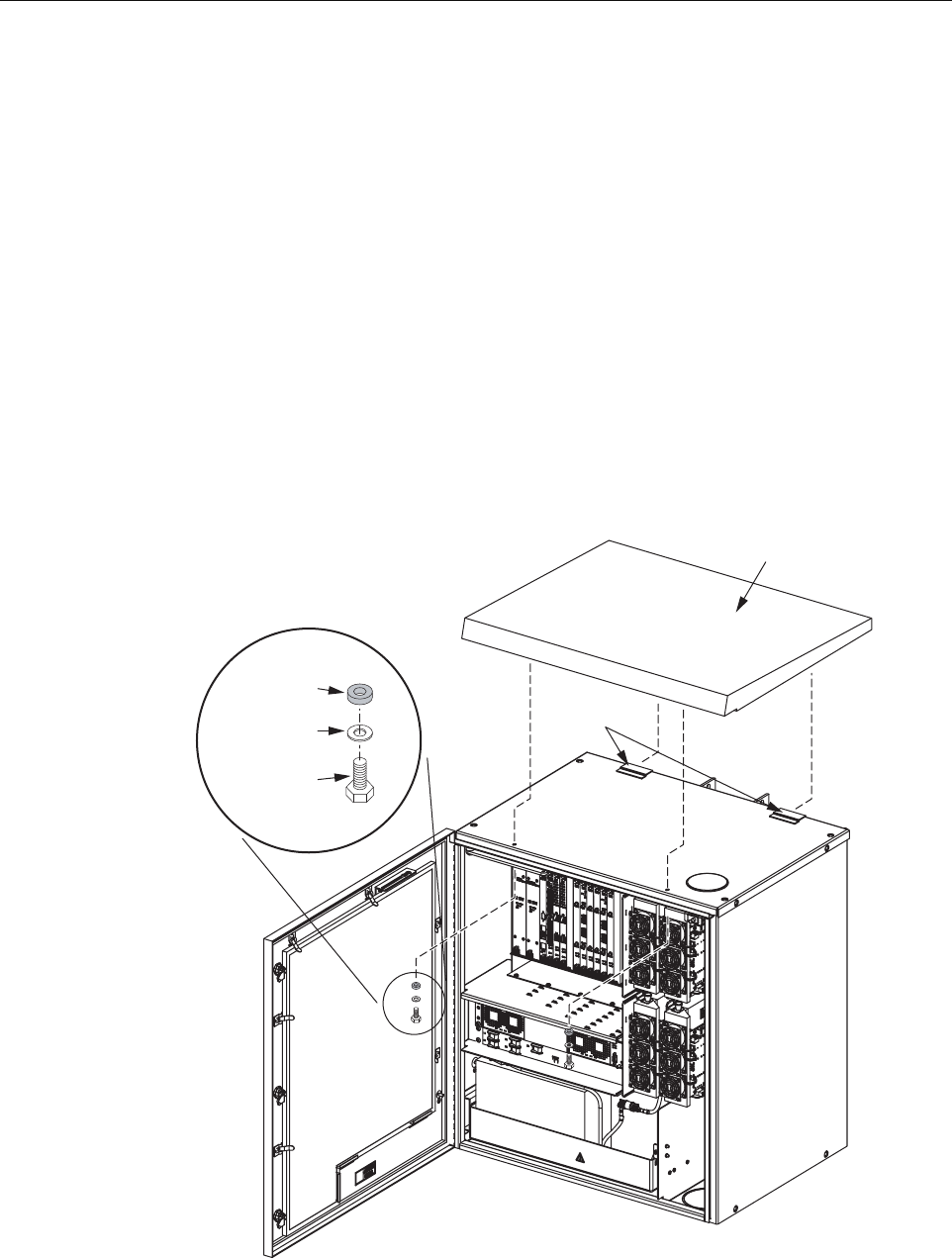
ADCP-75-210 • Issue 1 • March 2007
Page 43
© 2007, ADC Telecommunications, Inc.
2.7 Other Standard Installation Procedures
This section contains other procedures done at every installation after the RAN is mounted on a
wooden pole or concrete pad.
2.7.1 Installing a Solar Shield
Each RAN has a solar shield that mounts on top of the cabinet. Hardware for the solar shield can
be found in a bag fastened to the inside of the battery compartment. The hardware consists of
two 1/4 in. bolts, each with flat washer and sealing washer. Use the following procedure to
install the solar shield. Refer to Figure 31.
1. Remove the solar shield from its packaging.
2. Place a lock washer and flat washer and then the sealing washer on each 1/4 in. machine
bolt.
3. Using the key provided, open the RAN door.
Figure 31. Installing the Solar Shield
TANGS
RUBBER
SEALING
WASHER
FLAT
WASHER
1/4 x 20
HEX HEAD
BOLT
EACH SIDE
SOLAR
SHIELD
21339-A

ADCP-75-210 • Issue 1 • March 2007
Page 44
© 2007, ADC Telecommunications, Inc.
4. Locate the two 1/4 in. machine bolts, each with flat washer and sealing washer, in a bag
fastened to the inside of the battery compartment.
5. Place the solar shield on the top of the RAN.
6. Push the solar shield backward until it extends slightly beyond the back of the cabinet then
pull it forward catching the two tangs of the solar shield on the top of the RAN.
7. Locate the two clearance holes on the left and right sides just inside the door frame.
8. Align the solar shield threaded holes with the clearance holes and insert the two 1/4 in.
machine bolts in the hole.
9. Using a 7/16 in. nut driver or socket screw, tighten the two 1/4 in. machine bolts to secure
the solar shield. Tighten to 6 ft.-lbs.
2.7.2 Installing a Ground Wire
Each RAN is designed with provisions for connecting to earth ground. Earth grounding is to be
done in accordance with the National Electric Code and local building code. Two ground studs
for connecting the ground wire are located on the back of the RAN (Figure 32). A 2-hole
compression type lug terminal should be installed on the ground studs for connecting a #6 AWG
copper grounding wire.
The following material must be supplied by the installer:
• Panduit LLCF6-14B-L or equivalent (X2)
• Two-hole compression lug terminal for #6 AWG wire
• #6 AWG wire
• Connector for attaching the wire to an approved ground source
The following tools are required to perform this procedure:
• Compression pliers for #6 AWG grounding lug
• Wire cutters
• Wire stripper
Use the following procedure to install the ground wire:
1. Obtain a length of #6 AWG (4 mm) copper wire for use as a cabinet grounding wire.
2. Crimp the #6 AWG copper grounding wire to the compression lug.
3. Secure the compression lug to the back of the cabinet.
4. Route the free end of the grounding wire to an approved earth ground source.
5. Cut the grounding wire to length and connect it to the earth ground source as specified by
local code.
Caution: For proper equipment operation, an approved earth ground connection must be
provided. The recommended minimum wire size is #6 AWG copper wire.
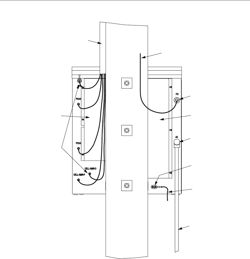
ADCP-75-210 • Issue 1 • March 2007
Page 45
© 2007, ADC Telecommunications, Inc.
Figure 32. Cable Connection Points
2.7.3 Installing RF Cabling
RF cabling on the RAN connects the RF antenna to the RF input on the back of the RAN. There
are five Type N receptacles on the antenna and five Type N receptacles on the back of the RAN,
identified in Table 21 on page 47.
There are two main steps in installing RF cables: weatherproofing the cables, and routing and
securing the cables.
21287-A
RF LINE CONDUIT
(FROM ANTENNA)
TYPE N CONNECTORS
FOR ANTENNA AND
GPS CONNECTORS
LEFT
RAIN
SHIELD
FIBER OPTIC
CONDUIT
FIBER OPTIC
ENTRANCE
RIGHT
RAIN
SHIELD
POWER ENTRANCE
220 VAC PRIME POWER
220 VAC RIGID
CONDUIT
GROUND
WIRE
GROUND
LUG

ADCP-75-210 • Issue 1 • March 2007
Page 46
© 2007, ADC Telecommunications, Inc.
2.7.3.1 Weatherproofing RF Cables
RF cables should be weatherproofed before being installed. The following materials are
required (customer supplied):
• 3M 8426-9M cold shrink
• 3M Skothkote Electrical Coating 14853
Use the following procedure to weatherproof the RF cables:
1. Prior to connecting the RF cables to either the RAN or antenna, place one 3M 8426-9M
cold shrink kit over the cable end, then connect the cable end to its intended termination
point. Follow the manufacturer’s directions, which are included with each kit.
2. After the cold shrink has been applied, coat the entire length of the cold shrink material
with the 3M Scotchkote Electrical Coating, number 14853.
2.7.3.2 Routing and Securing RF Cables
For cable installation, the following materials are required (customer supplied):
• 10 Type N male plugs (CommScope PN: 540ANM or equivalent)
• Coax cable (CommScope PN: FXL540OPE or equivalent)
• Electrician’s tape
• Water seal
Use the following procedure to route and secure the RF cabling:
1. Measure from the antenna base connectors to the RAN connectors to determine the coax
cable length including service loops and drip loops. Refer to Figure 25 on Page 35.
2. Install the Type N plugs on each end of each of the RF cables.
3. Attach each end of the cables to the appropriate connectors on the antenna base and the
RAN. Refer to Figure 33 and Table 21.
4. Tighten each connector to 20 ft.-lbs.
5. After each connector is tightened, cover the entire connection with electrician’s tape, then
wrap the connection in water seal and finally cover the water seal with wraps of
electrician’s tape.
Note: Read and understand the manufacturer’s instructions prior to using these products.
Note: Right angle connectors may not be needed if there is enough space or if the coax
cable is flexible enough to create a proper bend radius in the cable. Reference the coax
cable manufacturer specifications for allowable bend radii.
Note: A cable sweep test is highly recommended. When testing the RF and GPS coaxial
cables, use a matched load. The VSWR should be 1:1:1. The return loss should be 26.444
dB or better.
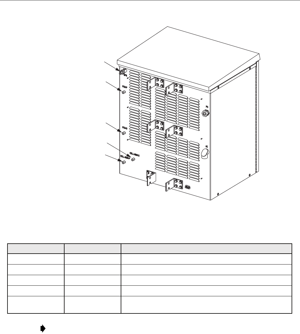
ADCP-75-210 • Issue 1 • March 2007
Page 47
© 2007, ADC Telecommunications, Inc.
Figure 33. Installing the RF Cables
2.7.4 Installing Pre-Connectorized Indoor/Outdoor Fiber Optic Cable
Fiber optic cable installation consists of routing a pre-connectorized outdoor-rated fiber optic
cable from an external splice enclosure to the NXD RAN cabinet, routing the cable into the
cabinet, and then breaking out the individual fibers for connection. The NXD RAN has a fiber
interface on the front of the Synchronous Interface (SIF) Module in the RAN chassis. The fiber
enters the cabinet on the rear side.
Table 21. RAN Antenna Ports and Antenna Base Ports
LABEL ON RAN LABEL ON ANTENNA BAND
GPS GPS Global Positioning System (GPS)
PCS-P PCS-T PCS primary receive path and transmits from PCS A, B or F
PCS-D PCS-B PCS diversity receive path and transmits from PCS D, E or C
CELL/SMR-D CELL/SMR-D Cell/SMR primary receive path and transmits from Cell A”/A
CELL/SMR-P CELL/SMR-P Cell/SMR diversity receive path and transmits from SMR A or
Cell B/B’
Note: When building out RANs, connect the quadplexers that will contain the first PCS
bands to the top of the PCS antenna element. On the Phasar antenna, this is marked on the
base PCS-T.
21278-A
GPS
PCS-P
PCS-D
CELL/SMR-P
CELL/SMR-D
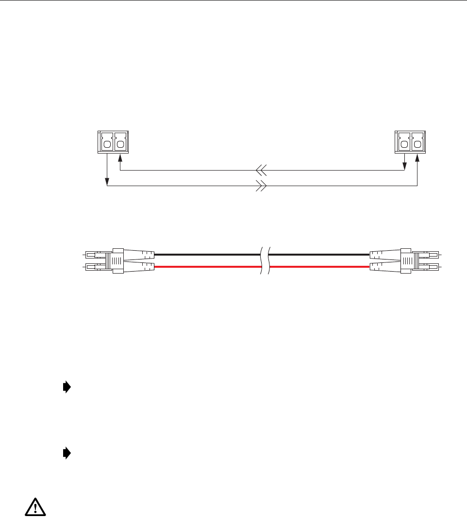
ADCP-75-210 • Issue 1 • March 2007
Page 48
© 2007, ADC Telecommunications, Inc.
All fiber optic cable connections require single-mode Dual-LC type connectors.
Figure 34 shows the basic configuration of the optical path between the Hub SIF and the RAN
SIF. For optical specifications, refer to Table 2 on page 6.
Figure 34. Optical Path Between Hub SIF and RAN SIF
For fiber cable ingress, the RAN is equipped with a nylon fiber optic connector located on the
rear side of the cabinet. The connector accommodates cables of a diameter in the range .38 to
.50 inches (.97 to 1.27 cm).
Use the following procedure to install the fiber optic cable:
1. Route the connectorized end of the fiber optic cable from the splice enclosure (not
provided) to the rear side of the cabinet. Estimated length of cable is 30 feet (9 meters)
although this is dependent upon distance from the splice enclosure.
Note: If the installer has a larger cable, the manufacturer (Hubbell Inc.) makes bushings
that fit this connector in the following size ranges: .500-.625, .625-.750, .750-.875, .875-
1.00, 1.00-1.125 inches.
Note: The routing of an Outside Plant (OSP) fiber optic cable from the Hub to a splice
enclosure in the vicinity of the RAN cabinet and the splicing of selected OSP cable fibers
to the fibers in the outdoor-rated cable is the responsibility of the installer.
Warning: This equipment uses a Class 1 Laser according to FDA/CDRH rules. Laser radiation
can seriously damage the retina of the eye. Do not look into the ends of any optical fiber. Do not
look directly into the optical transmitter of any unit or exposure to laser radiation may result.
An optical power meter should be used to verify active fibers. A protective cap or hood MUST
be immediately placed over any radiating transmitter or optical fiber connector to avoid the
potential of dangerous amounts of radiation exposure. This practice also prevents dirt particles
from entering the connector.
FIBER PORT
TX RX
FIBER PORT
TX RX
REVERSE PATH
BASIC CONFIGURATION BETWEEN HUB SIF SFP AND RAN SIF SFP
END-TO-END OPTICAL CONNECTOR/CABLE ASSEMBLY DIAGRAM
FORWARD PATH
21353-A

ADCP-75-210 • Issue 1 • March 2007
Page 49
© 2007, ADC Telecommunications, Inc.
2. Install the compression nut and an appropriate sized split ring and bushing over the cable
end. Note that the beveled side of the split ring should face toward the compression nut.
3. Insert the end of the cable into the fiber entry opening on the bottom of the cabinet and
pull the cable into the cabinet.
4. Connect fiber to the LC receptor located on the SIF electronic module. For location, refer
to Figure 11 on Page 16.
5. Pull back any excess fiber from within the NXD cabinet.
6. Tighten the compression nut on the fiber entry connector body to secure the cable.
7. Seal all connections.
2.7.5 Installing AC Power
Prime power for the RAN is 240 VAC, 20 Amps, single phase. A separate service disconnect
and lightning arrestor for each RAN must be installed with proper grounding. An electric meter
is optional depending on local agreements.
A non-connectorized #14 AWG 3-wire power cable is provided with the RAN cabinet for the
AC power connections. The power cable is connected to a wiring harness within the cabinet and
is approximately 20 feet (6 meters) long. The stub end of the cable must be routed out of the
cabinet through conduit to an external junction box (not provided). At the junction box, the
power cable must be connected to the AC power system wiring. The RAN electrical input fitting
is located on the right rear of the cabinet, labeled “AC.”
The AC power cable provides three wire leads for Line, Neutral, and Ground connections. All
AC wires must be run within conduit. The interface at the RAN is a 1 in. (2.54 cm) 90 degree
receptor elbow.
For installation of AC power, the following materials are required (customer provided):
• Electrical conduit
• Conduit fittings
• Connector sealant material
The following tools are required to perform this procedure:
• Wire cutters
• Wire strippers
• Conduit cutter
• Conduit bender
Note: The fiber should not have armored jacketing which may be a source for Electro-
Magnetic Interference (EMI).
Note: Power interfacing for the RAN must be performed by a licensed electrician.

ADCP-75-210 • Issue 1 • March 2007
Page 50
© 2007, ADC Telecommunications, Inc.
Use the following procedure to install the AC power wiring:
1. Install outdoor conduit between the the AC power junction box and the AC power fitting
(rigid 90 degree receptor elbow) on the back of the cabinet.
2. Use a UL approved outdoor conduit connector (not provided) to connect the conduit to the
AC power junction box.
3. Route the AC power cable through the conduit to the AC junction box.
4. Install the required AC power supply wires between the AC junction box and the AC
circuit breaker box (by the junction box not within the RAN).
5. Strip off the insulation from the AC power cable wire leads and from the AC supply wires
and connect the AC power cable wires to the AC supplier cable.
6. Connect the AC power to the AC wiring harness.
7. At the AC circuit breaker box, connect the AC power supply load wire(s) to a 20 Amp
circuit breaker.
8. Place the circuit breaker in the ON position and then test the connectorized AC power
cable within the cabinet for proper voltage levels and correct polarity.
9. Place the circuit breaker in the OFF position when testing is complete.
2.7.6 Installing Backup Batteries (Extended or Glitch)
Backup batteries for the RAN may be either two-hours-extended or five minutes glitch. The
batteries will need to be installed and under charge before they will be able to provide full
service. Battery storage life is one year in an environmentally controlled area. Batteries should
be checked prior to installation. Each battery should measure 12.6 V or greater across terminals.
Any battery that measures less should not be used. Refer to the battery manufacturer’s manual
for specific information including charging recommendations, tests, and maintenance.
2.7.6.1 Battery Safety Rules
For safety purposes, observe the following DO’s and DON’T’s when installing the batteries or
performing battery tests and maintenance:
• DO use qualified personnel only for battery maintenance
• DO follow all battery and charger manufacturer maintenance instructions
Note: All electrical work must comply with local codes and requirements. A locally
licensed electrical contractor is best qualified to perform this work. For operation at less
than 20 Amps, consult with ADC Technical Service.
Danger: Use extreme caution when working with high voltage AC power. Ensure all power is
disconnected before working on power circuits.
Note: A reducer fitting must be provided to accommodate any size change to the conduit.

ADCP-75-210 • Issue 1 • March 2007
Page 51
© 2007, ADC Telecommunications, Inc.
• DO wear protective equipment (face shield, goggles, gloves) when working with or
around battery systems.
• DO use proper lifting techniques when working with batteries.
• DO use insulated tools when working on batteries.
• DO remove all rings and metal watchbands before working on batteries.
• DON’T service batteries individually. Replace pack as a unit.
• DON’T replace a defective pack with an alternate type. Use only the replacement packs
provided by ADC.
• DON’T lift batteries by their terminals.
• DON’T place tools, unconnected cables, or metal objects to rest on top of the batteries.
• DON’T use any chemical cleaners (ammonia, bleach, etc.) to clean batteries.
• DON’T remove vent caps or add anything to sealed, maintenance-free batteries.
• DON’T smoke, cause sparks, or carry an open flame near any battery system.
• DON’T approach any energized battery system that shows signs of over-charging or over
discharging (severe swelling, cover deformation, vent caps popping off). Disconnect and
isolate the battery system from all charging and discharging circuitry before approaching
the system.
• DON’T circumvent any device installed by the battery or charger manufacturer for the
purpose of protecting the battery system. These devices include fuses, circuit breakers,
disconnects, switches, etc.
2.7.6.2 Battery Installation
Use the following procedure to install the batteries:
1. Open the RAN door.
2. Turn off the battery disconnect switch (labeled DISC) on the low voltage disconnect unit
in the RAN chassis. For location, refer to Figure 19 on Page 24. The LVD LED will light
up (red) when the batteries are disconnected.
3. Move the gravity latch in the battery drawer to the up position. Refer to Figure 35.
Warning: Do not short battery connections together or to ground. The battery pack has high
current capacity and can cause burns or serious personal injury when shorted.
Warning: To avoid personal injury or fire damage, do not incinerate or mutilate the battery. Do
not short the battery terminals and do not store or operate the battery in an airtight container.
Warning: The batteries contain hazardous materials. Deliver defective batteries to an
authorized disposal center for disposal or recycling.
Caution: Before connecting batteries, be sure to turn off the low voltage connect switch located
on the rectifier. The LED will be OFF.
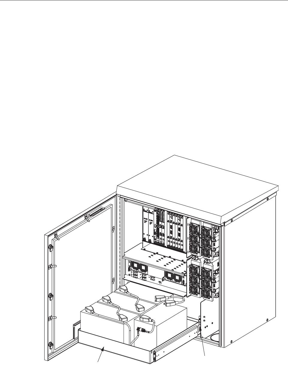
ADCP-75-210 • Issue 1 • March 2007
Page 52
© 2007, ADC Telecommunications, Inc.
4. Pull out the battery drawer.
5. Move the gravity latch to the down position. Lock the telescopic slide into the locked out
position.
6. Install the batteries in the drawer as follows, referring to Figure 36 for extended batteries
and Figure 37 for extended batteries:
a. Place the batteries in the drawer in the configuration shown.
b. Wire the batteries in series as shown.
c. Find the wiring harness coiled up on the floor of the battery back up drawer and plug
the Anderson connectors together as shown.
7. Move the gravity latch up, push the battery drawer in, and move the gravity latch down.
8. Reconnect the battery disconnect switch (DISC) on the LVD unit. For location, refer to
Figure 19 on Page 24. The LVD LED on the low voltage disconnect unit should will turn
off when the batteries are reconnected.
Figure 35. Open Battery Drawer
21277-A
GRAVITY
LATCH
BATTERY
DRAWER
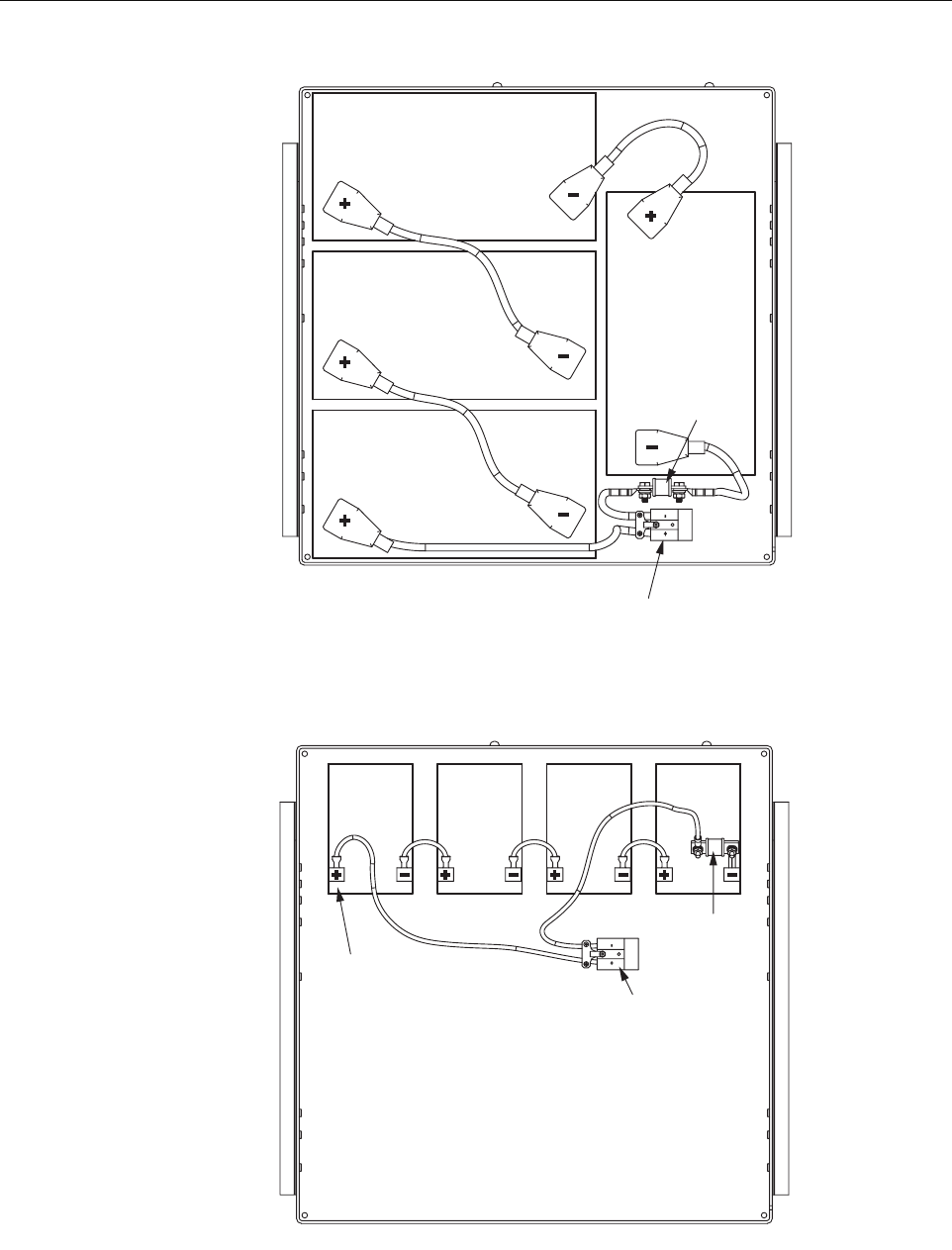
ADCP-75-210 • Issue 1 • March 2007
Page 53
© 2007, ADC Telecommunications, Inc.
Figure 36. Extended Batteries in Drawer
Figure 37. Glitch Batteries in Drawer
21288-A
70 AMP
FUSE
ANDERSON
CONNECTOR
21289-A
70 AMP
FUSE
ANDERSON
CONNECTOR
NOTE:
CUSTOMER TO COVER
EXPOSED TERMINALS
WITH ELECTRICAL TAPE.
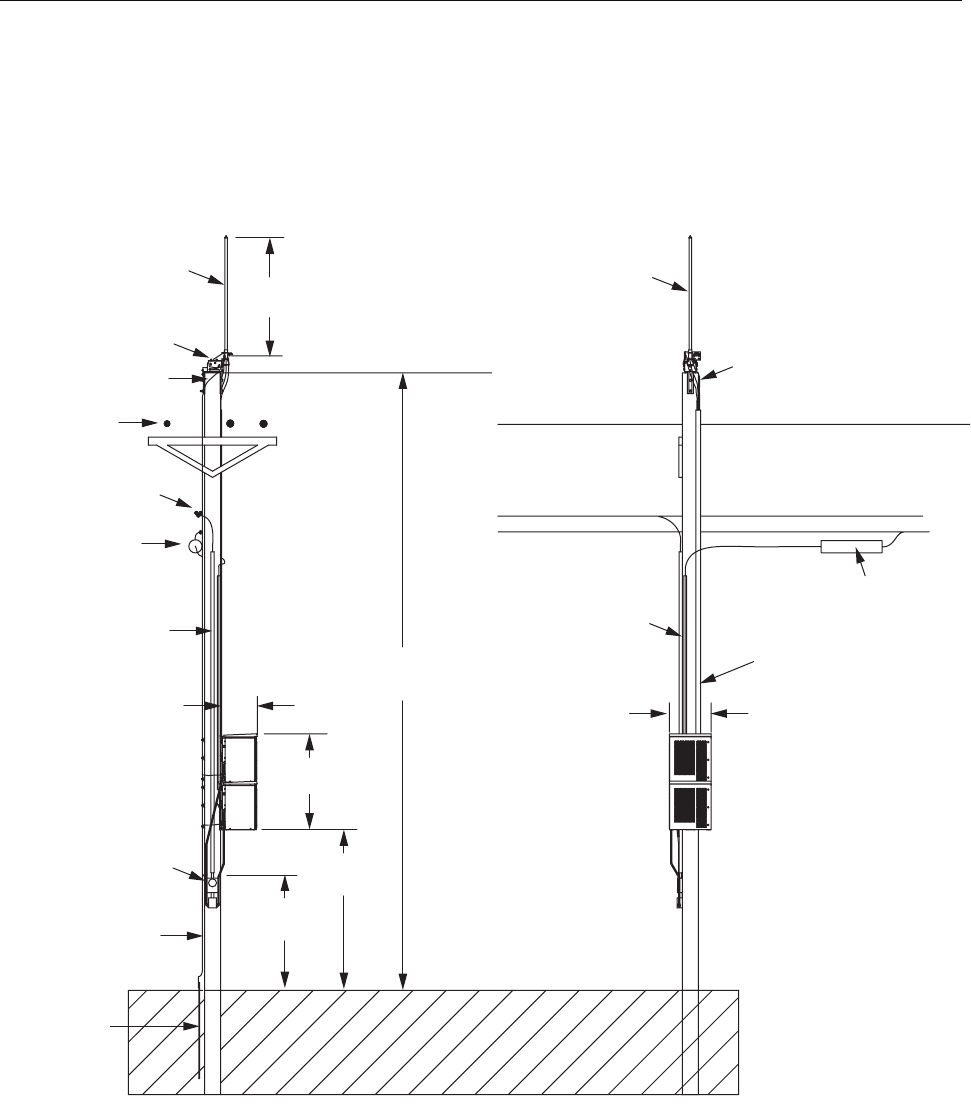
ADCP-75-210 • Issue 1 • March 2007
Page 54
© 2007, ADC Telecommunications, Inc.
3 INSTALLING AN EXTENSION RAN (POLE MOUNT)
Two RANs can be installed at the same location to provide up to eight bands at that location
using a common antenna. Each RAN requires its own separate power and RF cables and fiber
optical cable. Figure 38 shows a typical dual RAN pole mount installation.
Figure 38. Typical Dual RAN Pole-Mount Installation
Materials Required (Customer Supplied):
• Three galvanized steel bolts with tensile strength of 20,500 lbs. or greater, 3/4 inch
diameter, of a length appropriate to pole diameter
21295-A
ANTENNA
PRIMARY POWER
SECONDARY POWER LINE
FIBER SPLICE CAN
FIBER OPTIC LINE
FRONT
VIEW
31.25 IN.
(79.4 CM)
1.5 IN. SCHEDULE 40
POLE RISER FOR
FIBER OPTIC LINES
CARLTON PT. NO.
59010N OR
EQUIVALENT
3 IN. SCHEDULE 40
CONDUIT FOR RF CABLES
CARLTON PT. NO.
49013-010 OR
EQUIVALENT
RF CABLES
TO RAN
(5 REQUIRED)
ANTENNA
ANTENNA
MOUNTING
BRACKET
100 IN.
(254 CM)
GROUND WIRE
TO ANTENNA
PRIMARY
POWER
SECONDARY
POWER
FIBER
2 IN. SCHEDULE 40
CONDUIT FOR POWER IN
CARLTON PT. NO.
49011-010 OR
EQUIVALENT
SIDE
VIEW
27.5 IN.
(69.85 CM)
7 FT. (2.1 M)
TYPICAL
JUNCTION
BOX
#6 AWG COPPER
GROUND WIRE TO
METER BOX, RAN,
AND ANTENNA
6 FT. (1.8 M)
TYPICAL
10 FT. (3 M)
TYPICAL
38.6 FT.
(11.8 M)
TYPICAL
COPPER
GROUND
ROD
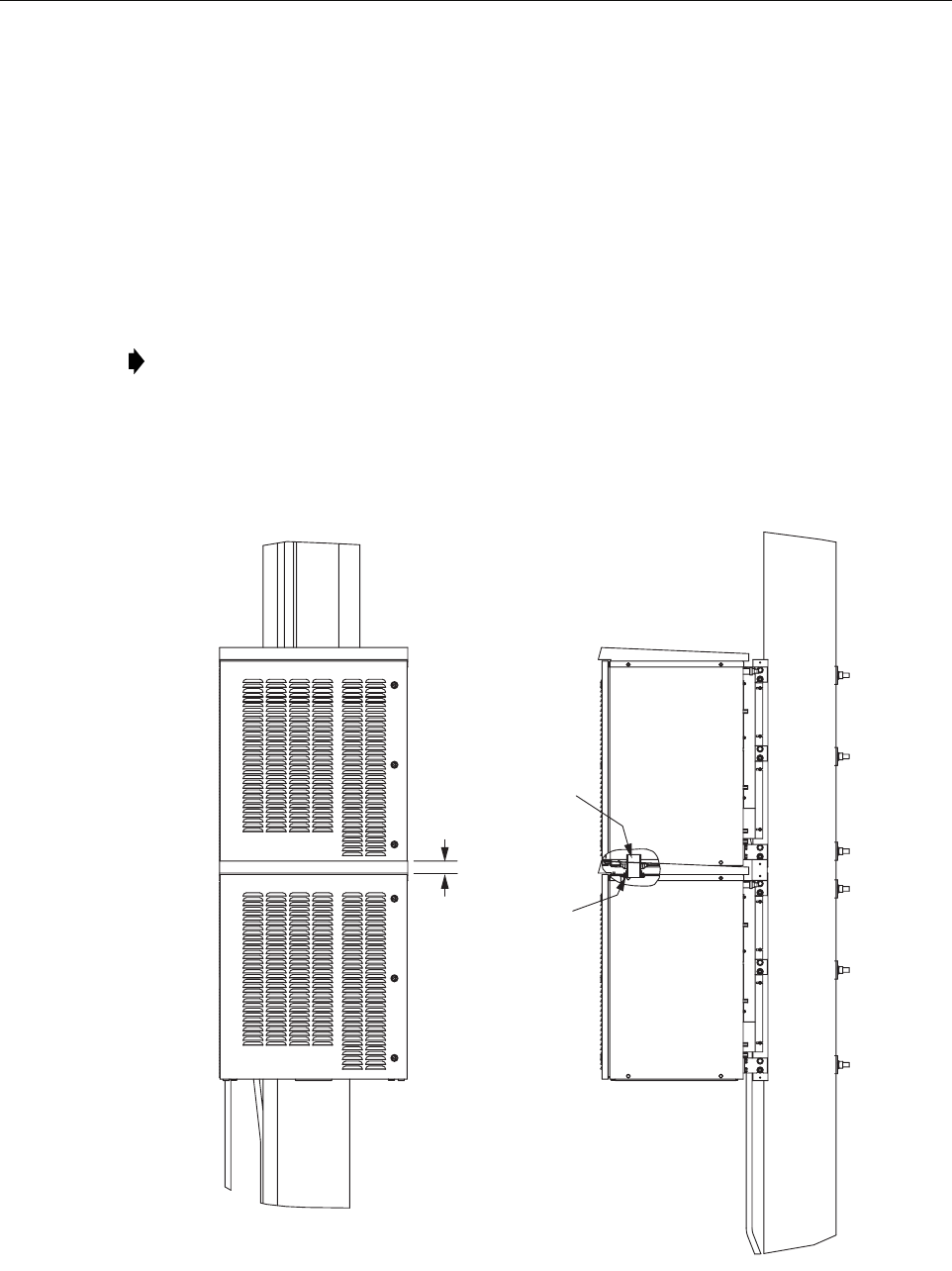
ADCP-75-210 • Issue 1 • March 2007
Page 55
© 2007, ADC Telecommunications, Inc.
• Three nuts, three flat washers, three 3 in. square curved washers, and three split ring
washers for bolts
Materials Required, ADC Supplied:
• RAN fixturing angle P/N 1001509P001 (X2)
• 1/4-20 X 3/4 hex bolts (X4)
• 2 in. through hull bulkhead fitting
• Flexible grommet
Use the following procedure to install an expansion RAN. Refer to Figure 39.
1. Open the existing RAN door.
2. Remove the solar shield from the existing RAN. Refer to the solar shield installation
procedure in Section 2.7.1 on Page 43 and do the steps in a reverse order.
Figure 39. Dual RAN Pole Mount
Note: This procedure assumes that the expansion RAN is installed on a utility pole
directly above the existing RAN.
21296-A
1.50 IN.
(3.8 CM)
2 IN. (5.08 CM)
BULKHEAD FITTING
SUPPLIED WITH
EXTENSION RAN
KENNARD
FLEXIBLE GROMMET
SUPPLIED WITH
EXTENSION RAN

ADCP-75-210 • Issue 1 • March 2007
Page 56
© 2007, ADC Telecommunications, Inc.
3. If RF cables will be routed from the existing RAN M/MCPLR or P/MCPLR module to the
extension RAN, remove the hole seal plugs located on the top right of the existing RAN
and on the bottom right of the extension RAN.
4. Bolt the fixturing angle to each side the expansion RAN pole mount bracket bottom holes
using the two 1/4-20 X 3/4 hex bolts.
5. Raise the assembly above the existing RAN and align the bottom of the fixturing angle
with the top of the existing pole mount bracket.
6. Bolt the fixturing angle to each side of the existing RAN pole mount bracket top holes
using the two 1/4-20 X 3/4 hex bolts.
7. Install the extension RAN pole mount bracket, RAN cabinet, and rain shields following
the instructions in Section 2.5.3 on Page 36, Section 2.5.4 on Page 38, and Section 2.5.5
on Page 38, respectively.
8. Install a solar shield on the extension RAN following the instructions in Section 2.7.1 on
Page 43.
9. Install a grounding wire on the extension RAN following the instructions in Section 2.7.2
on Page 44.
10. Install the RF cables from the antenna to the extension RAN following the instructions in
Section 2.7.3 on Page 45.
11. Install the fiber optic cable from the Hub to the extension RAN following the instructions
in Section 2.7.4 on Page 47.
12. Install AC power in the extension RAN following the instructions in Section 2.7.5 on Page
49.
13. Install backup batteries in the extension RAN following the instructions in Section 2.7.6
on Page 50.
14. Close and secure both RANs.
Note: In this case, the multicoupler modules, the PAAs, and the GPS in the existing RAN
will be providing input into the extension RAN RDC module, the PAAs, and the STF
module (ANT input) for some or all of bands 5-8. The associated RF cables from the
multicouplers will be routed out of the top of the existing RAN and into the bottom of the
extension RAN.

ADCP-75-210 • Issue 1 • March 2007
Page 57
© 2007, ADC Telecommunications, Inc.
4 NON-STANDARD INSTALLATION PROCEDURES
This section contains other installation procedures that are not typically done at a RAN
installation. These procedures cover field installation of electronic modules and other
components like the RAN chassis fans.
4.1 Installing an Electronic Module
If installing an electronic module in the field, refer to the appropriate procedure in this section.
There is a procedure for each type of electronic module. For a comprehensive description of the
electronic modules including function, controls, and indicators, refer to the appropriate topic in
Section 1.7 on Page 10.
Typically, the RAN chassis is shipped populated with the appropriate modules based on the pre-
ordered system configuration. Installation of electronic modules is only required when
installing a new electronic module or when changing the the system configuration.
The electronic modules install into predetermined slots in the chassis identified by the labels on
the fan access panel above the chassis. For an illustration of the fan access panel labels and a
listing of the slots, refer to Section 1.7 on Page 10.
The interconnection diagram shown in Figure 40 and Figure 41 on the next two pages
summarizes the interconnections between the RAN chassis electronic modules and other
electronic components of the RAN such as rectifiers and PAAs.
Note: Not all options and features are supported in combination.
Warning: Electronic components can be damaged by static electrical discharge. To prevent
ESD damage, always wear an ESD wrist strap when handling electronic components.
Note: The interconnection diagram shows a typical configuration. Other configurations
are possible that would be interconnected slightly differently.
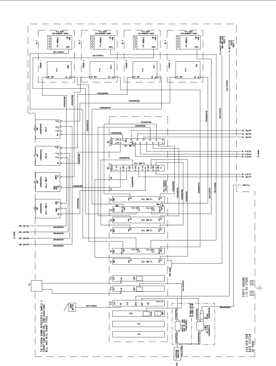
ADCP-75-210 • Issue 1 • March 2007
Page 58
© 2007, ADC Telecommunications, Inc.
Figure 40. RAN Interconnection Diagram Part 1
21372-A
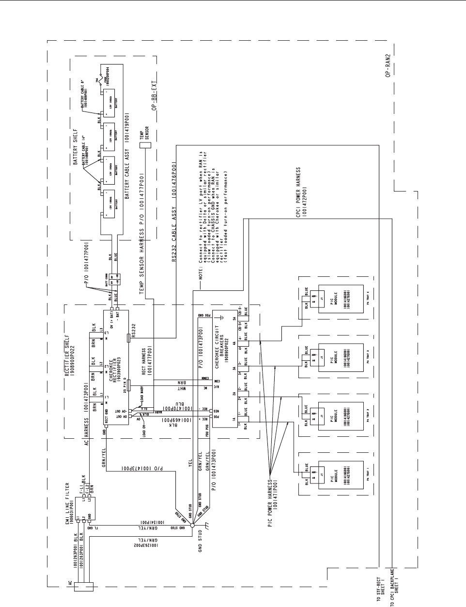
ADCP-75-210 • Issue 1 • March 2007
Page 59
© 2007, ADC Telecommunications, Inc.
Figure 41. RAN Interconnection Diagram Part 2
21373-A
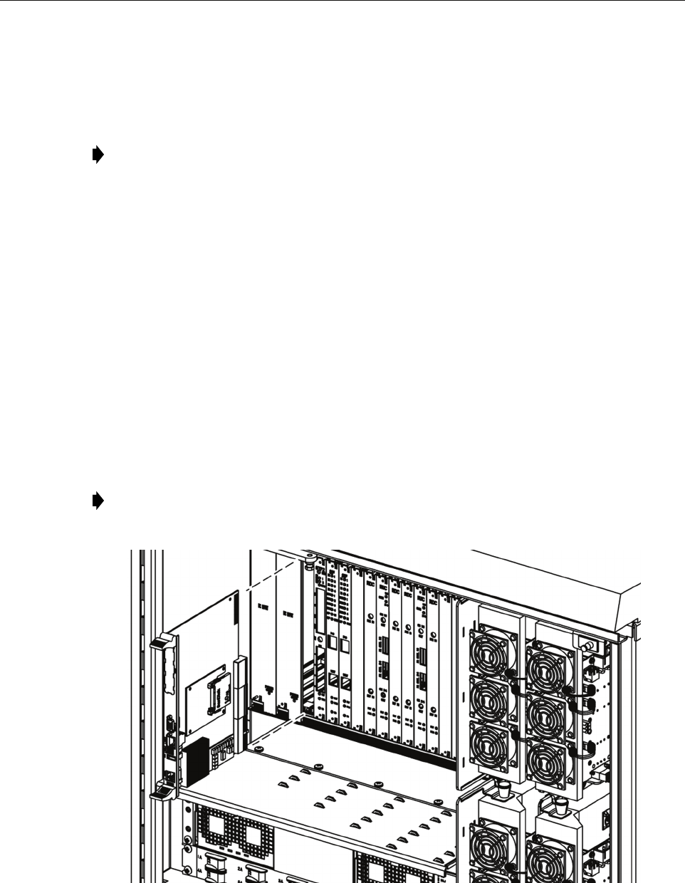
ADCP-75-210 • Issue 1 • March 2007
Page 60
© 2007, ADC Telecommunications, Inc.
4.1.1 Installing a Central Processing Unit (CPU) Module
The Central Processing Unit (CPU) module installs into Slot 5 of the RAN chassis. Only one
CPU may be installed in the RAN chassis.
Use the following procedure to install the CPU module (Figure 42):
1. Open the RAN door.
2. Locate the designated slot for the CPU module. The CPU module installs into Slot 5,
which is identified with a red colored card guide.
3. Remove the CPU module from the anti-static packaging and orient the module for
installation as shown in the figure.
4. Slide the CPU module into the designated slot within the RAN chassis.
5. Lock the IEL handles on the top and bottom of the CPU module into the cPCI chassis.
6. Tighten the two Phillips head screws inside the handles.
7. Connect the short CAT5e jumper (cable 1001478P001) between the “ENET” port on the
CPU module the “10BT” port on the SIF module.
21250-AX
Figure 42. Installing a CPU Module
Note: For a description of the CPU module including function, controls, and indicators,
refer to Section 1.7.2 on Page 13. For a RAN chassis interconnection diagram, refer to
Figure 40 on Page 58.
Note: If there are two SIF modules present, connect the cable to the first SIF module
(leftmost SIF module when viewed from the front of the chassis).
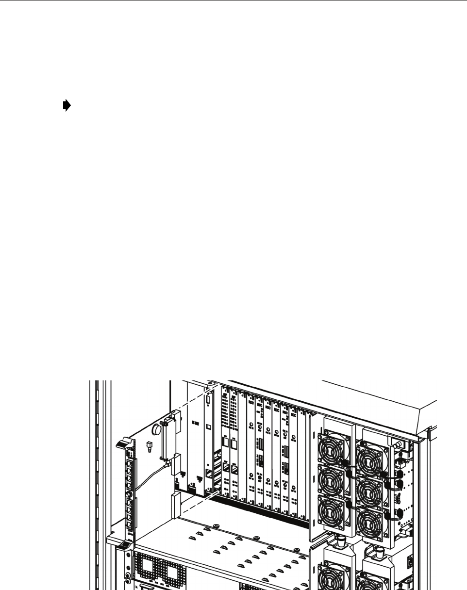
ADCP-75-210 • Issue 1 • March 2007
Page 61
© 2007, ADC Telecommunications, Inc.
4.1.2 Installing a Systems Interface (STF2) Module
The System Interface module (STF2) is installed into Slot 6 of the RAN Chassis. Only one
STF2 module may be installed per RAN chassis.
Use the following procedure to install the STF2 module (Figure 43):
1. Open the RAN door.
2. Locate the designated slot for the STF2 module. The module installs into Slot 6.
3. Remove the STF2 module from the anti-static packaging and orient for installation.
4. Slide the STF2 module into the designated slot within the RAN chassis.
5. Lock the IEL handles on the top and bottom of the STF2 module into the cPCI chassis and
tighten the handle screws.
6. Using cable 1001474P001, connect the RAN door switch to the RJ-45 connector labeled
DA (Door Alarm) on the front of the STF2 module.
7. Using cable 1955000P084, connect the GPS antenna to the SMA connector labeled ANT
(Antenna) in the center of the module.
8. Using cable 1001476P001, connect the RECT port on the STF2 module to the unlabeled
9-pin port on the Low Voltage Disconnect (LVD) unit. For location of the LVD port, refer
to Section 1.8.2 on Page 24.
21252-AX
Figure 43. Installing an STF2 Module
Note: For a description of the STF2 module including function, controls, and indicators,
refer to Section 1.7.3 on Page 14. For a RAN chassis interconnection diagram, refer to
Figure 40 on Page 58.
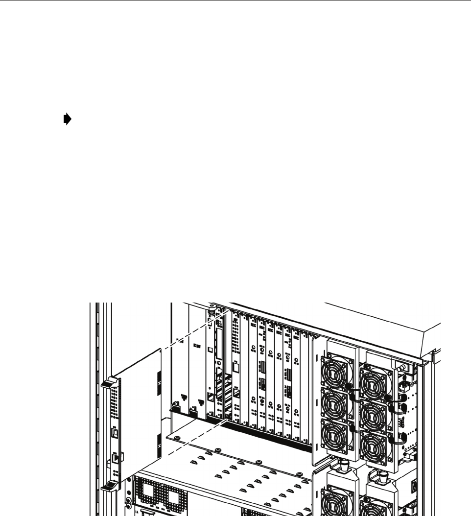
ADCP-75-210 • Issue 1 • March 2007
Page 62
© 2007, ADC Telecommunications, Inc.
4.1.3 Installing a Synchronous Interface (SIF) Module
The Synchronous Interface Module (SIF) is installed into Slot 7 or Slot 8 of the RAN chassis.
One SIF module is required for each two bands installed in the RAN. For the first two bands use
Slot 7. For the second two bands, use Slot 8.
Use the following procedure to install the SIF module (Figure 44):
1. Open the RAN door.
2. Locate the designated slot for the SIF module. The module installs into Slot 7 or Slot 8.
Refer to the introductory text above for more information.
3. Remove the SIF from the anti-static packaging and orient for installation.
4. Slide the SIF into the designated slot within the RAN chassis.
5. Lock the IEL handles on the top and bottom of the SIF module into the cPCI chassis and
tighten handle screws.
21252-AX
Figure 44. Installing an SIF Module
6. If this SIF module is being installed into Slot 7, connect the short CAT5e jumper (cable
1001478P001) between the “10BT” port on the SIF and the “ENET” port on the CPU
module. (For a slot 8 SIF, no cable is required.)
7. Carefully route the internal fibers to the front of the SIF module.
Note: For a description of the SIF module, including function, controls, and indicators,
refer to Section 1.7.4 on Page 15. For a RAN chassis interconnection diagram, refer to
Figure 40 on Page 58.

ADCP-75-210 • Issue 1 • March 2007
Page 63
© 2007, ADC Telecommunications, Inc.
8. If the optical transceiver is mounted into the SIF module, then connect the fiber to the dual
LC connector. If optical transceiver is not mounted into the SIF module, follow the SFP
installation procedure in Section 4.1.4 on Page 63.
4.1.4 Installing a Small Form-Factor Optical Transceiver (SFP)
The SFP installs in the front center of the SIF module.
Use the following procedure to install an SFP:-
1. Locate the transceiver socket on the front of the SIF and remove the port cover from the
socket.
2. The color of the transceiver extractor handle corresponds to the optical specifications of
the SFP and CWDM designations. Select the optical transceiver that is to be used to
communicate with the target RAN.
3. Remove the transceiver from the anti-static packaging and orient for installation.
4. Insert the optical transceiver into the socket until it locks into place.
5. Connect fiber or replace the optical transceiver dust cap if it was removed for installation.
4.1.5 Installing a RAN Down Converter (RDC or RDC2) Module
The RAN Down Converter (RDC) module may be installed into any of four slots in the RAN
chassis, depending on the band for which the module will be used. One RDC module is required
for each band. The four slots are:
• Slot 10 (labeled RDC A1): used for first band
• Slot 12 (labeled RDC A3): used for second band
• Slot 13 (labeled RDC A4): used for third band
• Slot 15 (labeled RDC A6): used for fourth band
Use the following procedure to install an RDC or RDC2 module (Figure 45):
1. Identify the slot designated RAN chassis slot for the RDC module. This will be Slot 10,
12, 13, or 15. For more information, refer to the introductory text above.
2. Remove the RDC module from the anti-static packaging and orient the module for
installation.
Note: For a description of the SFP, refer to Section 1.7.5 on Page 17. See also the
description of the SIF module faceplate in Section 1.7.4 on Page 15.
Note: For CWDM systems, it is extremely important that the correct wavelength be
installed in each SIF. Consult the site fiber plan for details
Note: For a description of the module including function, controls, and indicators, refer to
Section 1.7.6 on Page 17. For a RAN chassis interconnection diagram, refer to Figure 40
on Page 58.
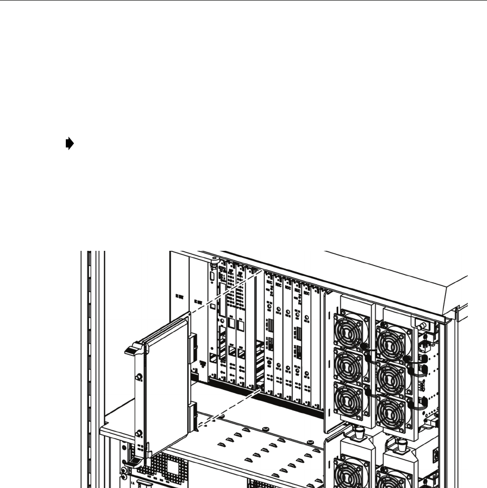
ADCP-75-210 • Issue 1 • March 2007
Page 64
© 2007, ADC Telecommunications, Inc.
3. Slide the RDC module into the designated slot within the RAN chassis.
4. Lock the IEL handles on the top and bottom of the RDC module into the chassis and
tighten the handle screws.
5. Using an SMA coaxial cable (1955000P081), connect one end to the PRI IN port on the
RDC module and the other end to the appropriate P OUT port on the C/MCPLR or P/
MCPLR module. Each P OUT port is associated with a different band.
6. Using an SMA coaxial cable (1955000P081), connect one end to the DIV IN port on the
RDC module and the other end to the appropriate D OUT port on the C/MCPLR or P/
MCPLR module. Each D OUT port is associated with a different band. For more
information on these ports, refer to the sections identified in the note above.
21235-AX
Figure 45. Installing an RDC Module
4.1.6 Installing a RAN Up Converter (RUC2.X or RUC3) Module
The RAN Up Converter (RUC2.X or RUC3) module may be installed into either of two slots in
the RAN chassis, depending on the band for which the module will be used. One module is
required for each two bands. The two slots are:
• Slot 11 (labeled RUC A2): used for first and second bands
• Slot 14 (labeled RUC A5): used for third and fourth bands
Note: For more information on the C/MCPLR module ports, see Section 1.7.9, 800 MHz
Multicoupler (C/MCPLR), on page 20. For more information on the P/MCPLR module
ports, see Section 1.7.10, 1900 MHz Multicoupler (P/MCPLR), on page 22.
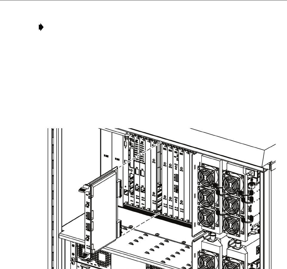
ADCP-75-210 • Issue 1 • March 2007
Page 65
© 2007, ADC Telecommunications, Inc.
Use the following procedure to install an RUC2.X or RUC3 module (Figure 46):
1. Identify the designated chassis slot for the RUC module. This will be Slot 11 or 14. For
more information, see introductory text above.
2. Remove the RUC module from the anti-static packaging and orient for installation.
3. Slide the RUC module into the designated slot within the RAN cPCI chassis.
4. Lock the IEL handles on the top and bottom of the RUC module into the cPCI chassis and
tighten handle screws.
21233-AX
Figure 46. Installing an RUC Module
5. Using cable 1955000P079, connect the CH1/3 connector on the RUC module to either of
the following as appropriate:
– RF IN port on PAA1 if RUC module is in slot A2
– RF IN port on PAA3 if RUC module is in slot A5
6. Using cable 1955000P079, connect the CH 2/4 connector on the RUC module to either of
the following as appropriate:
– RF IN port on PAA2 if RUC module is in slot A2
– RF IN port on PAA4 if RUC module is in slot A5
Note: For a description of the module including function, controls, and indicators, refer to
Section 1.7.7 on Page 19. For a RAN chassis interconnection diagram, refer to Figure 40
on Page 58.

ADCP-75-210 • Issue 1 • March 2007
Page 66
© 2007, ADC Telecommunications, Inc.
7. Using cable 1001475P001, connect the PA CTL1/3 connector on the RUC module to
either of the following as appropriate:
– CNTL port on PAA1 if RUC module is in slot A2
– CNTL port on PAA3 if RUC module is in slot A5
8. Using cable 1001475P001, connect the CTL 2/4 connector on the RUC module to either of
the following as appropriate:
– CNTL port on PAA2 if RUC module is in slot A2
– CNTL port on PAA4 if RUC module is in slot A5
4.2 Installing cPCI Chassis Air Baffles
The air baffles for the RAN chassis are used in all empty chassis slots. This is done to maintain
airflow around the chassis modules.
Use the following procedure to install air baffles:
1. Identify designated RAN Chassis cPCI slot for the cPCI air baffle.
2. Insert air baffle into designated slot on chassis and tighten screws.
4.3 Installing a Rectifier Module
To install a rectifier module, use the following procedure (Figure 47):
1. Connect cables following Section 22 on Page 66.
2. Slide the rectifier into the rectifier compartment.
3. Turn the gravity latch down to lock the rectifier in place.
Note: For a description of the rectifier including function, controls, and indicators, refer
to Section 1.8 on Page 23. For a RAN chassis interconnection diagram, refer to Figure 40
on Page 58.
Table 22. Rectifier Ports and Connections
RECTIFIER PORT CONNECTS TO USING CABLE COMMENTS
L1, L2, L3 EMI Line Filter
F-L1, F-L2
1001473P001 Connect black wire to F-L1 (on EMI Line Filter); connect
brown wire to FL-2
RECT GND GND Stud 1001473P001 Connect to cabinet ground stud
+BAT, - BAT Anderson con-
nector
1001477P001 Connect to Anderson connector in battery compartment;
connect black wire to 0V (+BAT) and blue wire to -BAT
OV OUT,
-OV OUT
temp sensor,
circuit break-
ers REC+ and
REC-
1001477P001
1001469P001
1001470P001
Place temperature sensor in battery compartment; connect
1001477P001 black wire to OV OUT and blue wire to -
OV OUT; connect 1001469P001 from rectifier OV OUT
to circuit breaker POS; connect 1001470P001 from recti-
fier -OV OUT to circuit breaker NEG
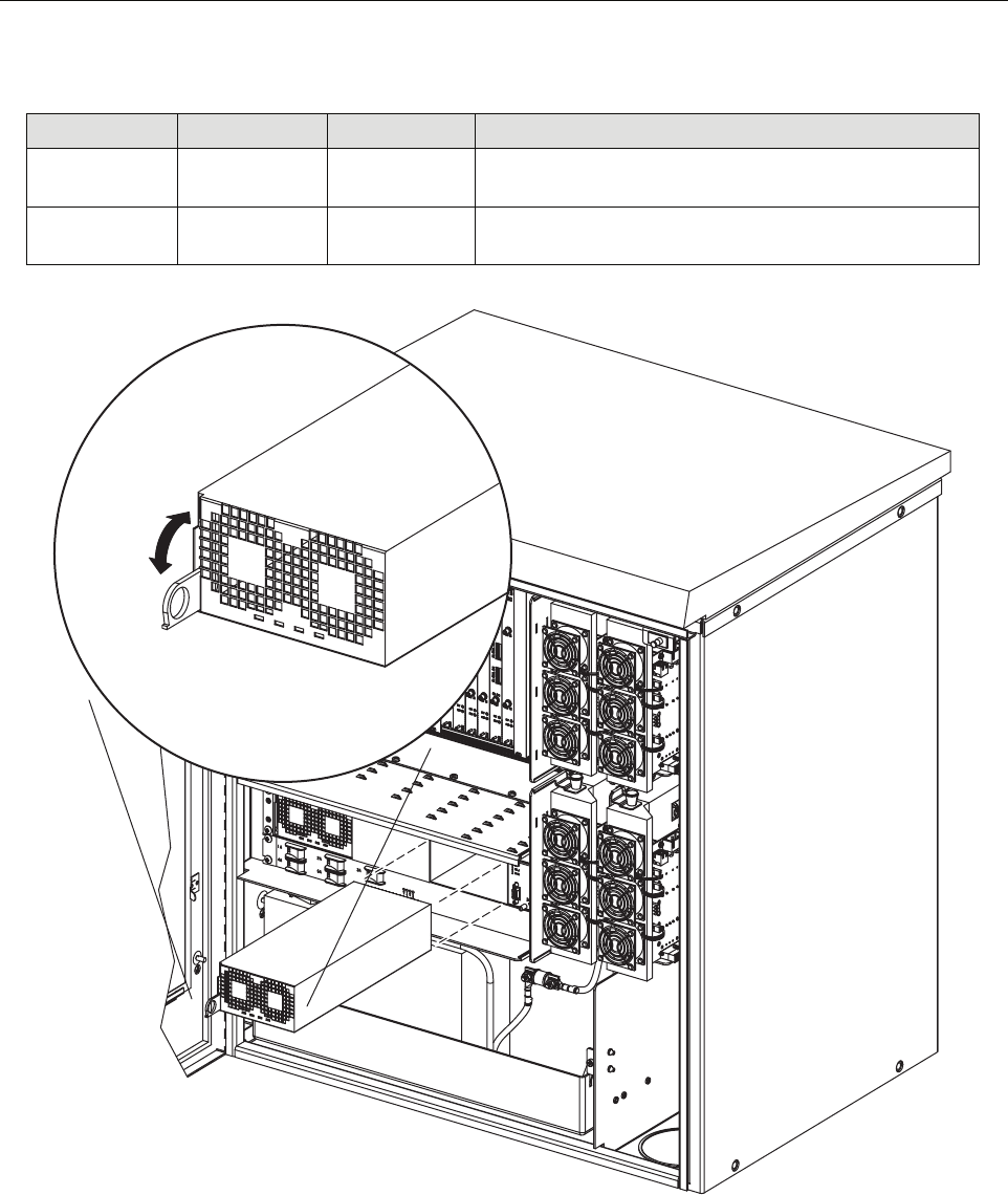
ADCP-75-210 • Issue 1 • March 2007
Page 67
© 2007, ADC Telecommunications, Inc.
Figure 47. Installing a Rectifier
25 Pin D Circuit breaker
panel N/C port
1001477P001 Connect white wire to circuit breaker N/C and brown wire
to COM
RS232 STF module
RECT port
1001476P001 Connect to STF module connector labeled RECT in RAN
chassis and RS-232 connector on the rectifier
Table 22. Rectifier Ports and Connections
RECTIFIER PORT CONNECTS TO USING CABLE COMMENTS
21274-A
LOCK
UNLOCK

ADCP-75-210 • Issue 1 • March 2007
Page 68
© 2007, ADC Telecommunications, Inc.
4.4 Installing a Compact PCI Power Supply (cPCI P/S) Module
The cPCI Power Supply Module installs into Slots 1 and 2 or Slots 3 and 4 of the RAN chassis.
One module is required per RAN chassis. Either set of two slot can be used. A second module
can be installed for redundancy.
Use the following procedure to install a cPCI Power Supply Module:
1. Identify the designated chassis slots for the module. This will be Slots 1 or 2 or Slot 3 and
4.
2. Remove the module from the anti-static packaging and orient for installation.
3. Slide the module into the designated slots within the RAN cPCI chassis.
4. Lock the IEL handles on the top and bottom of the RUC module into the cPCI chassis and
tighten handle screws.
4.5 Installing a Power Amplifier Assembly
The RAN holds up to four PAAs. One PAA is required for each band being supported. Use the
following procedure to install a PAA:
1. Connect cables per Table 23.
2. Slide the PAA into place.
Note: For a description of the cPCI P/S module including function, controls, and
indicators, refer to Section 1.7.1 on Page 12. For a RAN chassis interconnection diagram,
refer to Figure 40 on Page 58.
Note: For a description of the PAA including function, controls, and indicators, refer to
Section 1.9 on Page 25. For a RAN chassis interconnection diagram, refer to Figure 40 on
Page 58.
Table 23. PAA Connections
PAA PORT CONNECTS TO USING CABLE TYPE COMMENTS
I2C (J2) RUC module P/A
CNTL 2/4 or 1/3
1001475P001 RJ-45 connector. Connect cable from
PIC module port J2 (CNTL) to RUC
P/A CNTL 1/3 or P/A CNTL 2/4
48V PWR (J1) Circuit breaker
1A, 2A, 3A, or
4A port
1001471P001 Positronic 3-pin connector. Connect
cable from PIC module J1 port to cir-
cuit breaker 1A, 2A, 3A, or 4A port;
the circuit breaker has an individual
output for each of the four PAAs
RF OUT Plexer module
TX port
1955000P080 SMA connector. Connect cable from
PAA RF OUT to plexer port TX
RF IN RUC module CH
1/3 or CH 2/4
port
1955000P079 SMA connector. Connect cable from
PAA RF IN port to RUC module
CH 1/3 or CH 2/4 port
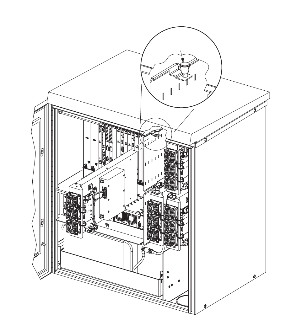
ADCP-75-210 • Issue 1 • March 2007
Page 69
© 2007, ADC Telecommunications, Inc.
Figure 48. Installing a PAA
21246-A
RAISE KNOB TO
UNLATCH RECTIFIER

ADCP-75-210 • Issue 1 • March 2007
Page 70
© 2007, ADC Telecommunications, Inc.
5 MAINTENANCE PROCEDURES
This section provides procedures for completing various maintenance tasks at the RAN. Refer
to the procedures in this section as necessary when scheduled maintenance is required. For fault
and troubleshooting procedures, refer to the system operation and maintenance manual, ADCP-
75-209.
5.1 cPCI Fan Replacement Procedure
The RAN chassis is equipped with a cooling fan that exhausts heated air from the chassis
assembly. Cool air enters the cPCI chassis through vent openings on the front door of the
cabinet. The recommended replacement interval is 60 months.
Use the following procedure to remove and replace the cPCI cooling fan.
1. Loosen the two thumbscrews that secure the fan access panel front door.
2. Open the hinged door (it swings down) to access the fan compartment.
3. Slide out the fan being replaced, note how it is connected, and then disconnect the fan.
4. Connect the new fan like the previous fan and slide it into the fan compartment.
5. Verify that the fan is running properly.
6. Close the fan panel door and secure it with the thumbscrews.
5.2 Cleaning or Replacing an Air Inlet Filter
The RAN cabinet air filter cleans the intake air before it enters the cabinets. The filter should be
cleaned approximately once per year and more often in extremely dirty environments. If the
cabinet temperature gradually rises over a long period of time and there are no fan failures, it is
possible that the filter is dirty and requires cleaning. Use the following procedure to clean the
cabinet air filter:
1. Open the RAN enclosure door and remove the inlet air filter tray door as shown in
Figure 49.
2. Pull the filter and away from its mounting slot at the bottom of the cabinet.
3. Gently tap the filter against your hand to dislodge the dirt. If necessary, use compressed air
or a vacuum cleaner to remove the dirt.
4. Carefully inspect the filter for holes or tears and replace if it is damaged.
5. Orient the filter with the airflow arrows pointed inside the RAN.
6. Close and secure the inlet air filter tray.
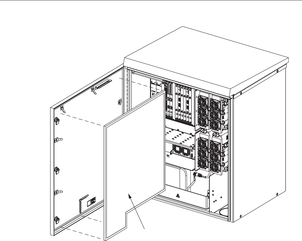
ADCP-75-210 • Issue 1 • March 2007
Page 71
© 2007, ADC Telecommunications, Inc.
Figure 49. Air Inlet Filter Tray
FILTER
21275-A
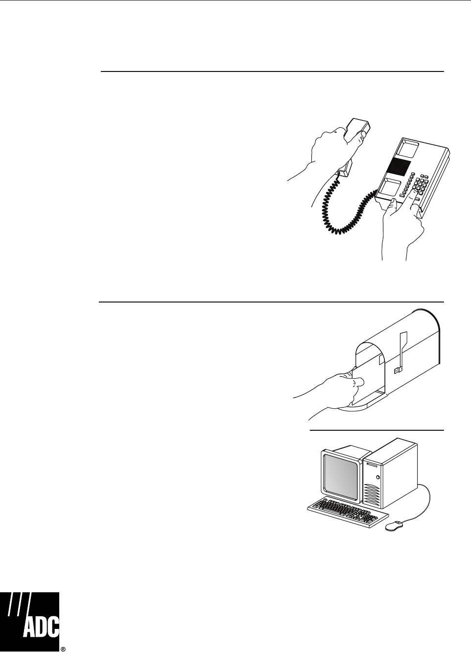
ADCP-75-210 • Issue 1 • March 2007
Page 72
© 2007, ADC Telecommunications, Inc.
6 CUSTOMER INFORMATION AND ASSISTANCE
© 2007, ADC Telecommunications, Inc.
All Rights Reserved
Printed in U.S.A.
13944-RM
WRITE:
ADC TELECOMMUNICATIONS, INC
PO BOX 1101,
MINNEAPOLIS, MN 55440-1101, USA
ADC TELECOMMUNICATIONS (S'PORE) PTE. LTD.
100 BEACH ROAD, #18-01, SHAW TOWERS.
SINGAPORE 189702.
ADC EUROPEAN CUSTOMER SERVICE, INC
BELGICASTRAAT 2,
1930 ZAVENTEM, BELGIUM
PHONE:
EUROPE
Sales Administration: +32-2-712-65 00
Technical Assistance: +32-2-712-65 42
EUROPEAN TOLL FREE NUMBERS
UK: 0800 960236
Spain: 900 983291
France: 0800 914032
Germany: 0180 2232923
U.S.A. OR CANADA
Sales: 1-800-366-3891 Extension 73000
Technical Assistance: 1-800-366-3891
Connectivity Extension 73475
Wireless Extension 73476
ASIA/PACIFIC
Sales Administration: +65-6294-9948
Technical Assistance: +65-6393-0739
ELSEWHERE
Sales Administration: +1-952-938-8080
Technical Assistance: +1-952-917-3475
Italy: 0800 782374
PRODUCT INFORMATION AND TECHNICAL ASSISTANCE:
Contents herein are current as of the date of publication. ADC reserves the right to change the contents without prior notice.
In no event shall ADC be liable for any damages resulting from loss of data, loss of use, or loss of profits and ADC further
disclaims any and all liability for indirect, incidental, special, consequential or other similar damages. This disclaimer of
liability applies to all products, publications and services during and after the warranty period. This publication may be
verified at any time by contacting ADC's Technical Assistance Center.
euro.tac@adc.com
asiapacific.tac@adc.com
wireless.tac@adc.com
connectivity.tac@adc.com
