ADDVALUE INNOVATION AVIATLASIP Maritime Satellite Terminal User Manual
ADDVALUE INNOVATION PTE LTD Maritime Satellite Terminal
UserManual.wiki
>
ADDVALUE INNOVATION
>
AVIATLASIP User Manual
>
User manual
Contents
1.
User manual
2.
User Manual
User manual
Navigation menu
Upload a User Manual
Namespaces
Wiki Guide
HTML
PDF
Info
Views
User Manual
Discussion / Help
Navigation
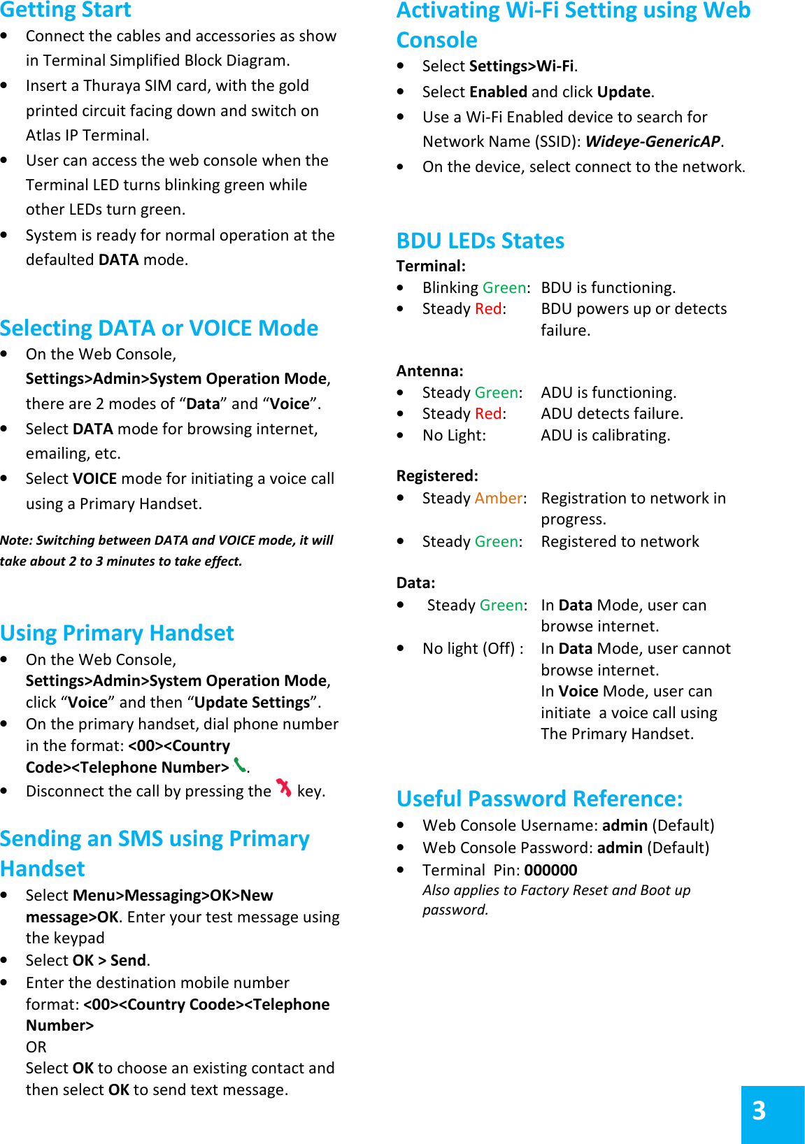
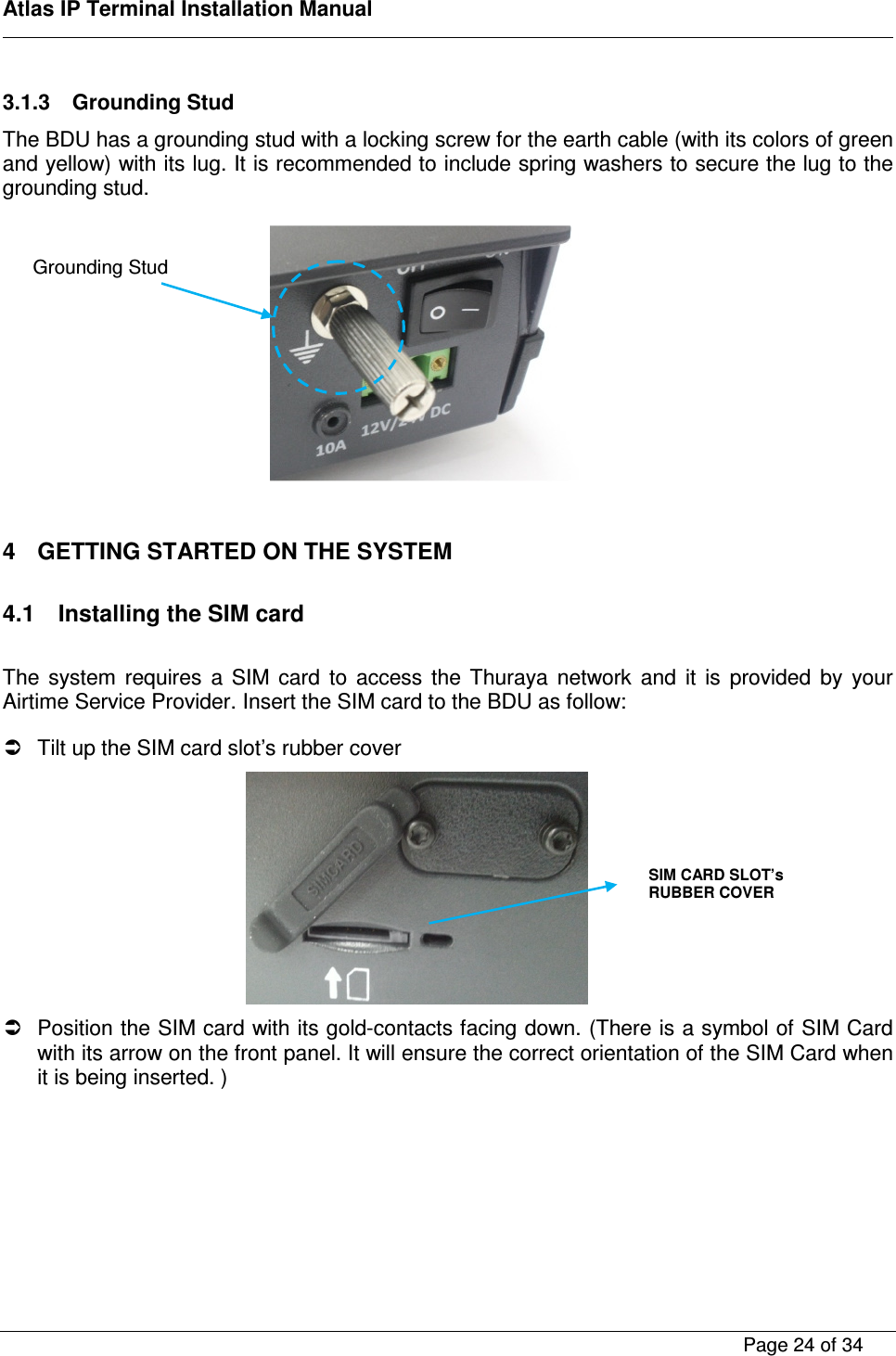
![Atlas IP Terminal Installation Manual Page 5 of 34 Declaration of Conformity: Addvalue Innovation Pte Ltd., 8, Tai Seng Link, Level 5 (Wing 2), Singapore 534158. declares under our sole responsibility that the Product, brand name as Thuraya and model: ATLAS IP, Maritime Broadband Satellite Terminal to which this declaration relates, is in conformity with the following standards and/or other normative documents: ETSI EN 301 489-1, -17, -19, -20, ETSI EN 301 444, ETSI EN 300 328, EN 60945, IEC 60950 – 1 AND EN 60950-1, We hereby declare that all essential radio test suite have been carried out and that the above named product is in conformity to all the essential requirements of Directive 1999/5/EC. The Conformity Assessment procedure referred to Article 10 and detailed in Annex [III] or [IV] of Directive 1999/5/EC has been followed with involvement of the following notified body(ies): TIMCO ENGINEERING, INC., P.O BOX 370,NEW BERRY, FLORIDA 32669. Identification mark: 1177 (Notified Body number) The technical documentation relevant to the above equipment are held at: · Addvalue Innovation Pte Ltd., 8, Tai Seng Link, Level 5 (Wing 2), Singapore 534158. ·Signed by Mr. Tan Khai Pang (Chief Technology Officer, September 29, 2014) and Mr. Prabakar Kuttaniseeri (Manager- Quality Management, September 29, 2014). SAFETY INSTRUCTIONS For the sake of safety and protection, read the manual before attempting to use Thuraya Atlas IP Terminal. The following general safety precautions must be observed during all phases of operation, service and repair of this equipment. Failure to comply with these precautions or with specific warnings elsewhere in this user guide violates safety standards of intended use of the terminal. Addvalue Innovation Pte Ltd assumes no liability for the customer's failure to comply with these requirements. Hazard Symbols Antenna Radiation Warning and Distance to other Radiation Equipment For safety reasons, all personnel must keep at least 2 meters from the ADU.](https://usermanual.wiki/ADDVALUE-INNOVATION/AVIATLASIP.User-manual/User-Guide-2423148-Page-5.png)
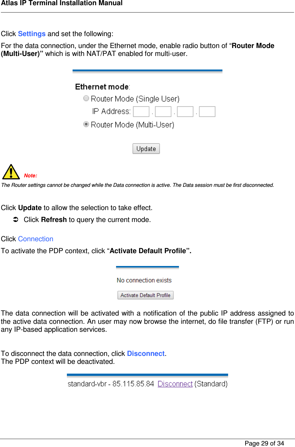
![Atlas IP Terminal Installation Manual Page 28 of 34 4.3.2 Data Connection Settings Click on the web console. Click Primary Profiles and set the following: Enable checkbox of “Set as default” and ensure “Standard” in the Profile Name. Enable radio button of “Standard” of Connection Type. Enable checkbox of “Always On (Auto PDP Context Activation)” Enable radio button of “Dynamic IP Address” of IP configuration. Note: The Standard profile is set as the default primary profile and the default connection type is standard (this is charged by the volume [in kilobytes] of data used). Click “Always On (Auto PDP Context Actviation)” checkbox if it is required to get the standard IP Data connection to be reconnected automatically in the event the connection is disconnected without user intervention, i.e. antenna blockage, etc.](https://usermanual.wiki/ADDVALUE-INNOVATION/AVIATLASIP.User-manual/User-Guide-2423148-Page-28.png)