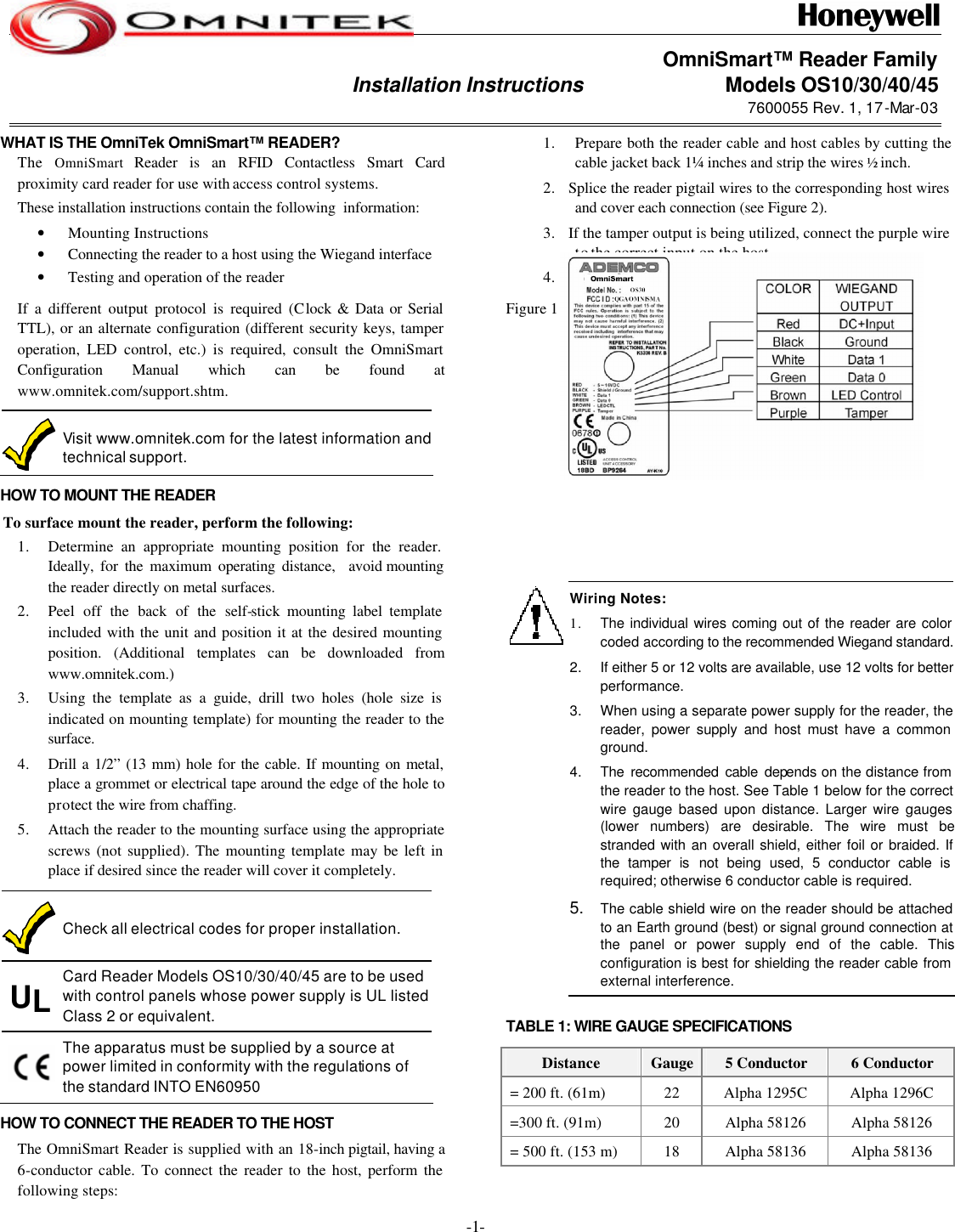
ADEMCO OmniTek OMNISMART Contactless Smart Card RFID Reader User Manual OS Series Installation Manual Revision 1

ADEMCO OmniTek Contactless Smart Card RFID Reader OS Series Installation Manual Revision 1

Manual

 -1- OmniSmart™ Reader Family Installation Instructions                           Models OS10/30/40/45 7600055 Rev. 1, 17-Mar-03  WHAT IS THE OmniTek OmniSmart™ READER? The  OmniSmart  Reader is an RFID Contactless Smart Card proximity card reader for use with access control systems. These installation instructions contain the following  information: • Mounting Instructions • Connecting the reader to a host using the Wiegand interface • Testing and operation of the reader If a different output protocol is required (Clock & Data or Serial TTL), or an alternate configuration (different security keys, tamper operation, LED control, etc.) is required, consult the OmniSmart Configuration Manual which can be found at www.omnitek.com/support.shtm.  Visit www.omnitek.com for the latest information and technical support. HOW TO MOUNT THE READER To surface mount the reader, perform the following: 1. Determine an appropriate mounting position for the reader. Ideally, for the maximum operating distance,  avoid mounting the reader directly on metal surfaces.  2. Peel off the back of the self-stick mounting label template included with the unit and position it at the desired mounting position. (Additional templates can be downloaded from www.omnitek.com.) 3. Using the template as a guide, drill two holes (hole size is indicated on mounting template) for mounting the reader to the surface. 4. Drill a 1/2” (13 mm) hole for the cable. If mounting on metal, place a grommet or electrical tape around the edge of the hole to protect the wire from chaffing. 5. Attach the reader to the mounting surface using the appropriate screws (not supplied). The mounting template may be left in place if desired since the reader will cover it completely.  Check all electrical codes for proper installation.  UL Card Reader Models OS10/30/40/45 are to be used with control panels whose power supply is UL listed Class 2 or equivalent.   The apparatus must be supplied by a source at power limited in conformity with the regulations of the standard INTO EN60950 HOW TO CONNECT THE READER TO THE HOST The OmniSmart Reader is supplied with an 18-inch pigtail, having a 6-conductor cable. To connect the reader to the host, perform the following steps: 1. Prepare both the reader cable and host cables by cutting the cable jacket back 1¼ inches and strip the wires ½ inch. 2. Splice the reader pigtail wires to the corresponding host wires and cover each connection (see Figure 2). 3. If the tamper output is being utilized, connect the purple wire to the correct input on the host. 4. Trim and cover all conductors that are not used. Figure 1 below shows how you should wire the reader to the host.           Wiring Notes: 1. The individual wires coming out of the reader are color coded according to the recommended Wiegand standard.2. If either 5 or 12 volts are available, use 12 volts for better performance. 3. When using a separate power supply for the reader, the reader, power supply and host must have a common ground. 4. The recommended cable depends on the distance from the reader to the host. See Table 1 below for the correct wire gauge based upon distance. Larger wire gauges (lower numbers) are desirable. The wire must be stranded with an overall shield, either foil or braided. If the tamper is not being used, 5 conductor cable is required; otherwise 6 conductor cable is required. 5. The cable shield wire on the reader should be attached to an Earth ground (best) or signal ground connection at the panel or power supply end of the cable. This configuration is best for shielding the reader cable from external interference. TABLE 1: WIRE GAUGE SPECIFICATIONS Distance Gauge 5 Conductor 6 Conductor  = 200 ft. (61m) 22 Alpha 1295C Alpha 1296C  =300 ft. (91m) 20 Alpha 58126 Alpha 58126  = 500 ft. (153 m) 18 Alpha 58136 Alpha 58136
-2-  Recommended cable is only a guideline, use any manufacturer that meets the gauge and shield specifications. Lower gauges (smaller numbers) have less resistance and are preferrable. The use of plenium cable may be required by the local building codes.  HOW TO TEST AND OPERATE THE READER The reader should be tested after wiring it to the host.  Do this by  performing  the following steps: 1. Power up the reader.  The LED and beeper will activate three times. This indicates that the reader is working properly. 2. Present an OmniSmart Contactless Smart Card to the reader. The LED will momentarily flash green and a short beep will be emitted (if the reader is the factory default configuration). This indicates that the card was read properly by OmniSmart.  3. After the card data is processed by the host, the host can then turn the LED green or yellow. Refer to the host description of the LED operation if the reader LED is controlled by the host. HOW TO USE THE COVERS OmniSmart readers include three different color covers. After installation and test, the cover should be installed to hide the mounting screws and det er vandalisim. Choose the desired color and place on the reader from the top first to engage the mounting tabs and then swing it down onto the reader. Secure the cover to the reader using the supplied Philips head screw or the supplied security screw. (A security tool is included in the package with the screws.) ERROR CONDITIONS  Whenever an error condition is signaled by the reader, the red LED is flashed accompanied by a “low tone” a number of times. The following table explains what error message is being conveyed by the number of flashes/beeps: # of Flashes  Meaning 4 The first byte of the data in the OmniTek format is invalid, i.e., it is not of type Wiegand, Clock & data, or Serial Text. 5 The Application Issuer data in the reader does not match what is on the card. 6 No matching cryptographics keys were found. Continually  A tamper condition exists SPECIFICATIONS   Electrical Characteristics: Frequency: 13.56 MHz Power Supply Type: Linear or switching; ripple < 30 MHZ @ 50 mVss Operating Voltage Range: 5.0 – 16 VDC (Operational down to 4.25 VDC)  Maximum input current: OS10 Standby: 35 mA Read: 40 mA OS30, OS40, OS45 Standby: 35 mA Read: 50 mA Tamper Output Open collector, active low, max.sink current is 30 mA  Maximum Cable Distance to Host: 500 ft. (150 meters) ISO Standards Supported ISO 14443A, 14443B, and 15693 Card Read Distance: (Ideal conditions) OS10 2 –  2.5 in (5.1 – 6.4 cm)” OS30 2.5 – 3.75 in. (6.4 – 9.5cm) OS40 2.5 – 3.5 in.(6.4 – 8.9 cm) OS45 2.5 – 3.5 in.(6.4 – 8.9 cm) Regulatory Approvals: USA:  FCC Part 15 B (UL 294 applied for) Canada: Industry Canada Europe: CE Listed Operating Temperature Range: -25° F to 145° F (-31°C to 63°C) Operating Humidity: 0 to 95% (non condensing) Suitable for outdoor use Dimensions: OS10: 3.15” (80mm) L x 1.58” (40mm) W x 0.50” (12.8mm) D  OS30: 5.71” (145mm) L x 1.69” (43mm) W x 0.79” (20mm) D OS40: 4.33” (110mm) L x 2.96” (75mm) W x 0.59” (15mm) D OS45: 3.5” (89mm) L x 3.5” (89mm) W x 0.59” (15mm) D
-3- For additional information on the Wiegand™ Protocol, see “Access Control Standard  – Wiegand Card Reader Interface SIA AC-01 (1996.10)” which can be purchased from SIA (see www.siaonline.org)
 -4-   FEDERAL COMMUNICATIONS COMMISSION (FCC) Part 15 STATEMENT This equipment has been tested to FCC requirements and has been found acceptable for use. The FCC requires the following statement for your information: This equipment generates and uses radio frequency energy and if not installed and used properly, that is,  in strict accordance with the manufacturer's instructions, may cause interference to radio and television reception. It has been type tested and found to comply with the limits for a Class B computing device in accordance with the specifications in Part 15 of FCC Rules, which are designed to provide reasonable protection against such interference in a residential installation. However, there is no guarantee that interference will not occur in a particular installation. If this equipment does cause interference to radio or television reception, which can be determined by turning the equipment off and on, the user is encouraged to try to correct the interference by one or more of the following measures: • If using an indoor antenna, have a quality outdoor antenna installed.  • Reorient the receiving antenna until interference is reduced or eliminated.  • Move the radio or television receiver away from the receiver/control. • Move the antenna leads away from any wire runs to the receiver/control. • Plug the receiver/control into a different outlet so that it and the radio or television receiver are on different branch circuits. If necessary, the user should consult the dealer or an experienced radio/television technician for additional suggestions. The user or master may find the following booklet prepared by the Federal Communications Commission helpful: "Interference Handbook" This booklet is available from the U.S. Government Printing Office, Washington, DC 20402. The user shall not make any changes or modifications to the equipment unless authorized by the Installation Instructions or User's Manual.  Unauthorized changes or modifications could void the user's authority to operate the equipment.  CE CERTIFICATION DECLARATION OF CONFORMITY TO COUNCIL DIRECTIVE 89/336/EEC Standards to which conformity is declared: ETS 300 683, ETS 300 330 harmonized standard, low power emitters EN 50130-4:1998 Product family standard: Immunity requirements for components of fire, intruder and social alarm systems Issued by:        ADEMCO, 165 Eileen Way, Syosset NY 11791               Tel:  (516) 921-6704               www.ademco.com  Date of issue:   18-March-2003 Equipment type: Access Control Proximity Reader Model numbers    OS10, OS30, OS40, and OS45  Acknowledgements: OmniSmart is a registered trademark of Honeywell Corp.   File No.  BP9264 FCC ID=QGAOMNISMART 0636i
-5- OmniTek Limited Warranty OmniTek and its divisions, subsidiaries and affiliates ("Seller"), 149 Eileen Way, Syosset, New York 11791, warrants OmniSmart products to be in conformance with its own plans and specifications and to be free from defects in materials and workmanship under normal use and service for the life of the product. Seller's obligation shall be limited to repairing or replacing, at its option, free of charge for materials or labor, any product which is proved not in compliance with Seller's specifications or proves defective in materials or workmanship under normal use and service. Seller shall have no obligation under this Limited Warranty or otherwise if the product is altered or improperly repaired or serviced by anyone other than Ademco factory service. For warranty service, return product transportation prepaid, to Ademco Factory Service, 149 Eileen Way, Syosset, New York 11791. THERE ARE NO WARRANTIES, EXPRESS OR IMPLIED, OF MERCHANTABILITY, OR FITNESS FOR A PARTICULAR PURPOSE OR OTHERWISE, WHICH EXTEND BEYOND THE DESCRIPTION ON THE FACE HEREOF. IN NO CASE SHALL SELLER BE LIABLE TO ANYONE FOR ANY CONSEQUENTIAL OR INCIDENTAL DAMAGES FOR BREACH OF THIS OR ANY OTHER WARRANTY, EXPRESS OR IMPLIED, OR UPON ANY OTHER BASIS OF LIABILITY WHATSOEVER, EVEN IF THE LOSS OR DAMAGE IS CAUSED BY THE SELLER'S OWN NEGLIGENCE OR FAULT. Seller does not represent that the products it sells may not be compromised or circumvented; that the products will prevent any personal injury or property loss by burglary, robbery, fire or otherwise; or that the products will in all cases provide adequate warning or protection. Customer understands that a properly installed and maintained alarm may only reduce the risk of a burglary, robbery, fire or other events occurring without providing an alarm, but it is not insurance or a guarantee that such will not occur or that there will be no personal injury or property loss as a result. CONSEQUENTLY, SELLER SHALL HAVE NO LIABILITY FOR ANY PERSONAL INJURY, PROPERTY DAMAGE OR OTHER LOSS BASED ON A CLAIM THE PRODUCT FAILED TO GIVE WARNING. However, if Seller is held liable, whether directly or indirectly, for any loss or damage arising under this Limited Warranty or otherwise, regardless of cause or origin, Seller's maximum liability shall not in any case exceed the purchase price of the product, which shall be the complete and exclusive remedy against Seller. This warranty replaces any previous warranties and is the only warranty made by Seller on this product. No increase or alteration, written or verbal, of the obligations of this Limited Warranty is authorized.

Navigation menu