ADOBEAIR Evaporative Cooler Manual L9070132
User Manual: ADOBEAIR ADOBEAIR Evaporative Cooler Manual ADOBEAIR Evaporative Cooler Owner's Manual, ADOBEAIR Evaporative Cooler installation guides
Open the PDF directly: View PDF ![]() .
.
Page Count: 8
ModelNumber
SerialNumber
Themodeland serialnumbersfor your unitarelocatedins_ unit
on sideof blowerhousing.Recordthisinformationin thespace
allo_d above
Installation and Start-up
Thismanualwasdesignedtoprovideyou
and yourinstallerwithinformationneeded
to mount,operate,inspect,maintain,and
troubleshootyourcooler.
Atthe endofthisbookletthereis a chart
providingusefulhintsforincreasingthe
benefitsofyour evaporativecooler.
Thefirstsection,InstallationandStart-Up,
is especiallyforthe installer.
TheRegularMaintenancesectioncontains
operationand maintenanceinstructionsfor
the owner,whilethe Troubleshooting
sectionincludesinformationon commonly-
encounteredproblems.
Introduction .......................... 2
Mountingof DownDischargeModels ......... 2
Mountingof HorizontalModels ............. 2
Duct Placement ......................... 3
RequiredExhaust Openings ................ 3
ElectricalInstallation(Ducted Models) ....... 3
Motor Installation (Ducted Models) .......... 3
OverflowStandpipeInstallation............. 4
Drain LineInstallation .................... 4
Bleed-OffInstallation ..................... 4
AdjustingWater Leveland FloatLevel ......... 4
Generallns__*etion
Start-UpInspection ...................... 4
Start-UpChecklist ....................... 4
CabinetInspectionChecklist ............... 4
Regular Maintenance
ChangingCooler Pads .................... 5
AdjustingBeltTension.................... 5
Lubrication ............................ 5
CleaningWaterPump .................... 5
Drainingand Touch-Up................... 5
MountinEWindowModels
FlatSupport Installation .................. 6
ChainKitInstallation ..................... 6
ElectricalWiringon WindowModels ......... 6
........................ 7
GettingThe Mo_tFromYourCooler ......... 7
Note: Your warranty does not cover shipping damage. Report all shipping damage at once to dealer or carrier making delivery.
L9071024 *IFt9
INTRODUCTION
Evaporativecoolingworksontheprincipleofheatabsorptionbymoistureevaporation.Whena swimmer
leavesthewateron awindyday,he feelscool becausethe moistureon his bodyis evaporatingand
absorbingheat.
Yourevaporativecooler drawsexteriorair intospecialpads soakedwithwater,where the air iscooledby
evaporation,then circulatedintoyour home.
Yourevaporative cooler makes the best possible use of the evaporative process by metering the flow of
water, distributing it evenlythrough the filtermedia, and blowing a steady stream of cooled air into your
home. The air is then channeled through the building and vented out of the home through open
windows, doors or vents.
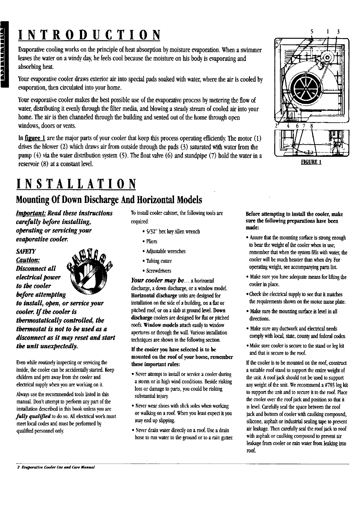
In _ are the major parts of your cooler that keep this process operating efficiendy. The motor (1)
drives the blower (2) which draws air from outside through the pads (3) saturated with water from the
pump (4) via the water distribution system (5). The float valve (6) and standpipe (7) hold the water In a
reservoir (8) at a constant level.
5 1 3
678
INSTALLATION
MountingOf DownDischargeAndHorizontalModels
lm_mportant:Read these instructions
carefully before installing,
operating or servicing your
evaporative cooler.
SAFETY
Caution: ,_
Disconnect all _ ]_
electrical power _
to the cooler _
before attempting
to install, open, or service your
cooler. If the cooler is
thermostatically controlled, the
thermostat is not to he used as a
disconnect as it may reset and start
the unit unexpectedly.
Evenwhile routinelyinspecting or servicingthe
inside,the cooler can be accidentallystarted. Keep
children and pets awayfrom the cooler and
electricalsupplywhen youare working on it.
Alwaysuse the recommended toolslisted in this
manual. Don't attemptto perform any part of the
installationdescribed in thisbook unless youare
fully qualified to do so. Allelectricalwork must
meet local cedes and must be performed by
qualifiedpersonnelonly
Toinstallcoolercabinet,thefollowingtoolsare
required:
•5/32"bexkeyAllenwrench
•Pliers
• Adjustablewrenches
• Tubingcutter
•Screwdrivers
Your cooler may he... a horizontal
discharge,a downdischarge,orawindowmodel.
Horizontaldischargeunitsare designedfor
installationonthesideofa building,onaflator
pitchedroof,or ona slabat groundlevel.Down
discharge coolersaredesignedforflator pitched
roofs.Windowmodels attacheasilytowindow
aperturesorthroughdiewall.Variousinstallation
techniquesareshowninthefollowingsection.
If the cooler youhaveselected is mbe
mountedon the roofof yourhome,remember
these important roles:
• Neverattempttoinstallorservicea coolerduring
a stormorinhighwindconditions.Besiderisking
lossor damagetoparts,youcouldbe risking
substantialinjury.
•Neverwearshoeswithslicksoleswhenworking
orwalkingona roof Whenyouleastexpectityou
mayendupslipping.
• Neverdrainwaterdirectlyona roof Usea drain
hosetorunwatertothegroundortoa raingutter.
Before attempting to install the cooler, make
sure the following preparations have been
made:
• Assurethatdiemountingsurfaceisstrongenough
tobeartheweightofdiecoolerwheninuse;
rememberthatwhendiesystemfillswithwater,the
coolerwillbemuchheavierthanwhendry.For
operatingweight,seeaccompanyingpartslist.
•Makesureyouhaveadequatemeansforlifdngthe
coolerinplace.
• Cheekdieelectricalsupplytoseethatitmatohes
therequirementsshownonthemotornameplate.
• Makesurethemountingsurfaceislevelinall
directions.
• Makesureanyductworkandelectricalneeds
complywithlocal,state,countyandfederalcodes.
• Makesurecooleris secureto thestandor legkit
andthatissecuretotheroof.
Ifthe cooler is to be mounted on the roof,construct
a suitable roof stand to support the entire weightof
the unit. Aroof jack should not be used tosupport
any weightof the unit. Werecommend a #785 leg ldt
to support the unit and to secure it to the roof. Place
the cooler over the roof jack and position so that it
is level.Carefullyseal die space betweenthe roof
jack and bottom of cooler withcaulking compound,
silicone, asphalt or industrial sealing tape to prevent
air leakage. Then carefullyseal the roof jack to roof
withasphalt or caulkingcompoundto prevent air
leakagefrom cooler or rainwater from leaking into
roof.
2 Evaporative Cooler Use and Care Manual
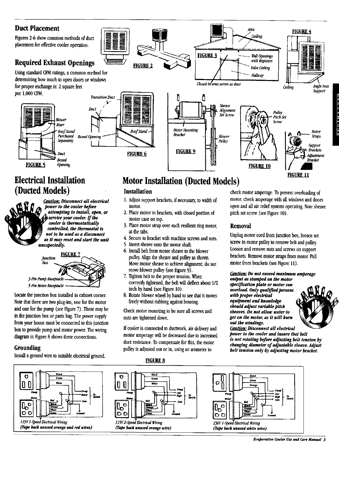
Duct Placement
Figures2-6showcommonmethodsof duct
placementforeffectivecooleroperation.
Required Exhaust Openings
UsingstandardCFMratings,a commonmethodfor
determininghowmuchto opendoorsor windows
for properexchangeis:2 squarefeet
per 1,000CFM.
i
B/ou,'m"
'Ri_er
/ - R_ofst_
Purchased Boxed
Separate_
TransilionDuct
Duct
FIGURES Opening
ElectricalInstallation
(DuctedModels)
Disconnect all electrical
power to the cooler before
attempting to install, open, or
_service your cooler. If the
cooler is thermostatically
controlled, the thermostat is
not to he used as a disconnect
as it may reset and start the unit
unexpectedly.
Locate the junctionbox installedin cabinet comer.
Note thatthereare twoplug-ins, one for the motor
and one for the pump (see Figure7). Thesemay be
in the junction box or parts bag. The power supply
from your house must be connected to this junction
box to provide pump and motor power.The wiring
diagram in Figure8shows these connections.
Grounding
Installagroundwiretosuitableelectricalground.
Shea*e
Alignment
Set Screw
MotorMounting
Bracket Blou_r
"Put#y
MotorInstallation(Ducted Models)
Installation
1.Adjustsupportbrackets,ifnecessary,towidthof
motor.
2. Placemotorinbrackets,withdosedportionof
motorcaseontop.
3. Placemotorstrapovereachresilientringmotor,
at thetabs,
4, Secureto bracketwithmachinescrewsandnuts.
5. Insertsheaveontothemotorshaft.
6. Installbeltfloramotorsheavetotheblower
pulley.Alignthesheaveandpulleyas shown.
Movemotorsheavetoachievealignment;donot
moveblowerpulley(seeFigure9).
7. Tightenbelttothepropertension.When
correctlytightened,thebeltwilldeflectabout1/2
inchbyhand(seeFigure10).
8. Rotateblowerwheelbyhandtoseethatit moves
freelywithoutrubbingagainsthousing.
Checkmotormountingtobe sureallscrewsand
nutsaretighteneddown.
ffcoolerisconnectedtoductwork,air deliveryand
motoramperagewillbe decreasedduetoincreased
duct resistance.Tocompensateforthis,themotor
pulleyis adjustedoutor in, usingan ammeterto
FIGURE10
Ceiling Anglelron
Support
checkmotoramperage.Topreventoverloadingof
motor,checkamperagewithallwindowsanddoors
openandallair reliefsystemsoperating.Notesheave
pitchsetscrew(seeFigure10).
Removal
Unplugmotorcordfromjunctionbox,loosenset
screwinmotorpulleytoremovebellandpulley.
Loosenandremovenutsandscrewsonsupport
brackets.Removemotorstrapsfrommotor.Pull
motorfrombrackets(seeFigure11).
_uBon: Do not ex_ed maximum amperage
output as stomped on the raotor
specification plate or motor can
overload. Only qtudifled pemons
with proper electrical
equipment and knowledge
should adjust variable pitch
sheaves. Do not allow water to
get on the motor,, as it wlll burn
out the windings.
Disconnect all electrical
power to the cooler and insure that belt
is not rotating before adjusting belt tension by
changing diameter of adjustable sheave. Adjust
belt tension only by adjusting motor bracket.
EIGURE8
OOk
-I
DO
l l5V l-Speed Electrical Wiring
(Tape back unused orange and t_l _res)
11572-sp¢edElectricalIViring
€°ra_ back unu_d ornnge wire)
L
23ov I.Speec ElectricalWiring
(Tape back unused white wire)
_m
Evaporative Cooler Use and Care Manual 3
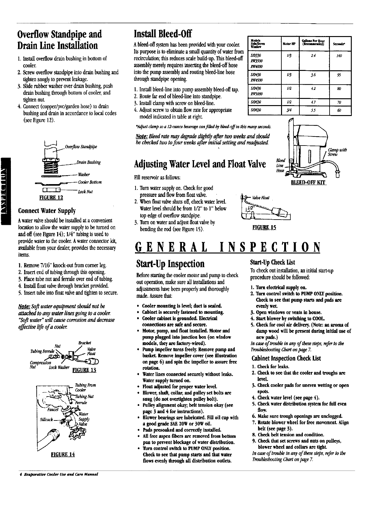
OverflowStandpipeand
DrainLineInstallation
1. Installoverflowdrainbushingin bottomof
cooler.
2. Screwoverflowstandpipeintodrainbushingand
tightensnuglytopreventleakage.
3. Sliderubberwasheroverdrainbushing,push
drainbushingthroughbottomof cooler,and
tightennut.
4. Connect(copper/pvc/gardenhose) todrain
bushinganddrainin accordancetolocalcodes
(seeFigure12).
ov_ow Sta,,dpi_,
ushing
._,_ CoolerBottom
_ _k t_ut
tmUe.E12
ConnectWaterSupply
Awatervalveshouldbeinstalledata convenient
locationtoallowthewatersupplyto beturnedon
andoff (seeFigure14);1/4"tubingisusedto
providewatertothecooler.Awaterconnectorkit,
availablefromyourdealer,providesthenecessary
items.
1. Remove7/16"knock-outfromcornerleg.
2. Insertendoftubingthroughthisopening.
3. Placetubenutand ferruleoverendofinbtug.
4. Installfloatvalvethroughbracketprovided.
5. Inserttubeintofloatvalveandtightento secure.
Note."Soflwaterequipmentshouldnot he
attachedto anywaterlinesgoingto a cooler
"Softwater"willcausecorrosionand decrease
effectivelife ofa cooler
Bracket
Nut V_
Nut Loci VTasberFIGURE 13
TubingFrom
InstallBleed-Off
Ableed-offsystemhasbeenprovidedwithyourcooler,
Itspurposeistoeliminatea smallquantityofwaterfrom
recil'x'ulation;thisreducesscalebuild-up,Thisbleed-off
assemblymerelyrequiresinsertingthebleed-offhose
intothepumpassemblyandroutingbleed-knehose
throughstandpipeopening.
1. Installbleed-lineinto pump assemblybleed-offtap.
2. Routefar end of bleed-lineintostandpipe.
3. Installclampwithscrew on bleed-line.
4. Adjustscrew toobtain flow ratefor appropriate
model indicatedin tableat right.
Modeb
s_
_D330
RW3500
RW4000
S/D#30
RW4500
Sm430
R_5000
S0630
S/0630
_qllom Perl_
MmorW_ (P_mded) Semtd**
1/3 i24 14o
I/3 _6 95
1/2 42 80
l/2 _7 70
y¢ 55 60
"Adjustclampsoa 12-ouncebeveragecanfilled by bleed-offin this manywcond$.
Note:Bleedratemaydegradeslightly after twoweeksandshould
he checkedtwotofour weeksafterinitialsettingand _ted
AdjustingWaterLeveland FloatValve
Fillreservoiras follows:
1. Turnwatersupplyon.Checkforgood
pressureandflowfromfloatvalve.
2. Whenfloatvalveshutsoff,checkwaterlevel.
Waterlevelshouldbe from1/2"to 1"below
topedgeofoverflowstandpipe.
3. Turnon water and adjust float valve by
bending the rod (see Figure 15).
C2amPLiH__ with
BLEED-OFFKIT
GENERAL INSPECTION
Start-UpInspection
Beforestartingthecoolermotorandpumptocheck
outoperation,makesureallinstallationsand
adjustmentshavebeenproperlyandthoroughly
made.Assurethat:
•Cooler mounting is level; duct is sealed.
•Cabinet is securely fastened to mounting.
•Cooler cabinet is grounded. Electrical
connections are safe and secure.
• Motor, pump, and float installed. Motor and
pump plugged into junction box (on window
models,theyarefactory-wired).
• Pump impeRer turns freely. Remove pump and
basket. Remove impeller cover (see illustration
on page 6) and spin the impeller to assure free
rotation.
•Water lines connected securely without leaks.
Water supply torned on.
•Float adjusted for proper water level.
•Blower, shaft, collar, and pulley set bolts are
snug (do not overtightco pulley bolt).
•Pulley alignment okay; belt tension okay (see
page 3 and 4 for instructions).
•Blower bearings are lubricated. Fill oil cup with
a good grade SAE 2OWor 3OWoiL
• Pads presoaked and correctly installed.
• MI free nspon fibers are removed from bottom
pan to prevent blockage of water distribution.
•Turn control switch to PUMPONLYposition.
Check to see that pump starts and that water
flows evenly through all distribution outlets.
Start-UpCheckList
To check out installation, an initial start-up
procedureshould be followed:
1. _at electrical supply on.
2. Turn control switch to PUMPONLYposition.
Chock to see that pomp starts aad pads use
evenly wet.
3. Openwindowsoryeatsinhouse.
4. Start blower by switching to COOL.
5. Check for cool air delivery. (Note: an aroma of
damp wood will be present during initial use of
new pads.)
In case of trouble in any of these steps, referto the
Troublesheoting Chart on page Z
CabinetInspection CheckList
1. Check for leaks.
2. Chock to see that the cooler and troughs are
level.
3. Check cooler pads for uneven wetting or open
spots.
4. Check water level (see page 4).
5. Check water distribution system for full even
flow.
6. Make sure trough openings are unclogged.
7. Rotate blower wheel for free movement. Align
belt (see page 3).
8. Check belt tension and condition.
9. Chockthat set screws and nuts on pulleys,
blower wheel and collars are tighL
In case of trouble in any of these steps, refer to the
Troubleshooting Chart on page 7.
4 Evaporative Cooler Use and Care MaRual
RE G ULAR MAINTE N ANC E
_,er_ _a_fa{maimeo_¢e_ allowyonto
enjoyalong mote_ieut settee life_m
_ur ¢_ter. Befores_i_g anymainte_,_ce
o_r,t_tou,r_ t_o%_ alloperatingand
alaim_¢e iugt_ous a_d u_serr_ _
camiousandwarnings.
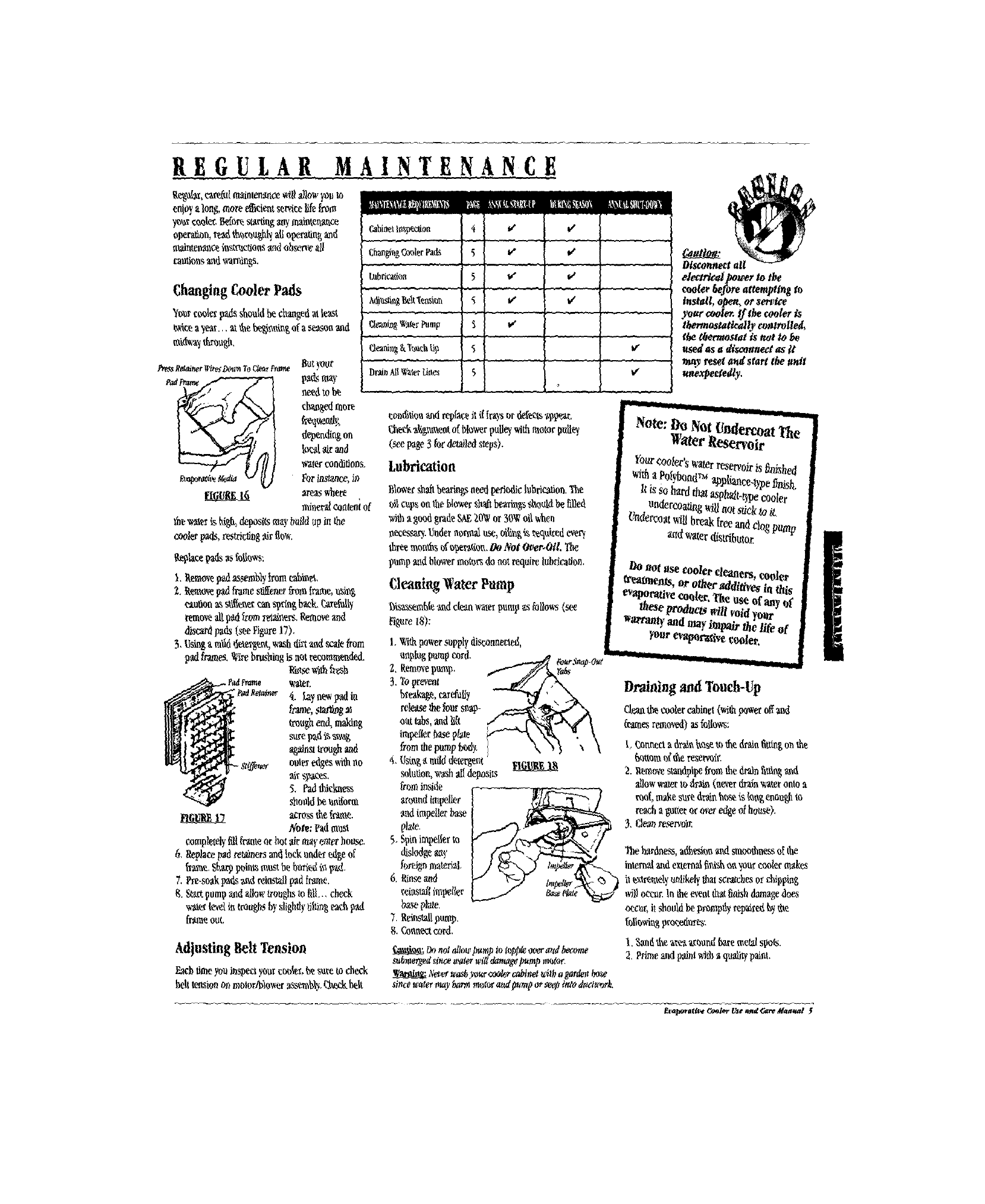
ChangingCoolerPads
'!nore_er padsshouldbe changedat loas_.
_c_ a _r... mtheb_i_,aiu_ofa se,_soaand
n_tdwa__r_o_.
L
t;han_r_g_oler Fads 5v" €
Labricatio_ 5to'
_2_ _ _ .....
Afflu_ng_it '_en.qm'n 5t,€"
Cle',_Jz_Wa_rPump _ v'
Pr_ R_aincrWi_yOon_aToC_r Fra_ BO{yOUr
_a,__ p_dsmay
needtobe
cha_gedmore
de_ending ou
W¢.._airand
wal_rcouditions.
£mt_rafft_aed_ _ _] r_r instauce,9)
n_oevdconteniof
the_a_r is _ depositsarq b_ildupiothe
coolerpads,restrie_ng_irflo_'.
t_placepadsas follo,_s:
Adjusting Belt Tension
_ch timeyouJbspeciyoure_t*r,€_suretocheck
hehtensiononmotnr/b_owerassm_y. _b_ckbelt
Dtai_AtIWalerUtt_s ]5
eon_tiouaM repheeit iftraysotdeP_,,s_.99,_ar.
_heth_g_eut ofblowerpulleywithmotorpull_
(seepage3 for_led _eps).
Lubrication
Blowe_sh_ bem_agsneedpe_od_cIobriCatiou.
_I copsontheblowershaftbearingssh,attidbe filled
wi_ a go_ grade_ 20_ or 30_ oilwhen
necessa_,tindernorma_use,oig_ is'zcqt_iredever_
threemoues ofu_r_ao_. OnNot Ov¢_.Otl,
pumpandblowermotor_do notrequirelubrication,
Cleanktg Water Pump
bisa_,.mhleaid dea_w_terpump_ts_ollows{_
Figure18):
1._th !_wer_ppl? disconnected,
unplug_mp cord.
I, Eemo_epump.
3.'inprevent
bre'aka_,car_y
rdeasethefours.c.-
outtabs,andlif{
tmpeffer_asep!ate
fromthepumptsxi_.
4,{,(si_amilddete_nt
_utioo, washalldeposits
frominside
_ruundimpeller
andimgeilerbase
plate.
5. Spinimpellert_
dislodge_'
fnreignmater_al.
6. _ arK}
reiastaffimpd(er
_aseplate,
7. Reinstallpumg.
8._uoect cord.
On nolallowImnll)in io_ oc_rattdbecome
suhn_d sincewaterwig _amagepump motor.
Neve¢washyo_ _cabind _* a_ardenbo_
sincgwaterOmybar_ rn_t_ a2_dottmp ov_eh,lttOttodttdu_prk.
_leari**l po_verto the
mulet _efore attempting to
_nstall, o_, or se_e
)'oar coot_ tf t_ cooler is
thermostatically eotttrolled,
the ¢#eernostatis _ot to
used as a dtsco#nect as it
may _l a_tdstart the tmff
unexpectedly.
Drainingand Touch-Up
dean_ coolercabinet(_ p_veroffand
_'amesrmo_l) asfolhws:
t, Cmmecia 6xa_huseto_e drainfi_ngonthe
_ttom o€_ rese_it_
2. Ill, ores_Apipe fromthedrain_t_g _d
allowwa_ertodrain (neverdrainvpaterontoa
_f, ma_esured_u ho_ is{(x_genon_ m
reacha gutteror peeredge4house).
3. Cle_zreservoir.
hardoess,adl_,,m andsmoothoesso_the
internalandexternalfi_i_ uuyoure_olermakes
it_xtremdyt_likelythatscratchesor d_ppiog
wil_oeet_rlo theevent_ finishdamagedoe,
occur,itshouldbepromptlyre_ed _ _e
followi_proeedm_:
1.3nod_.hezre__.rnundbabemetalspots.
2, Primeandl_Otwi_haqufirl paim.
£_oragft¥ _ooier Use _fld _ Mat#*tal 5
MOUNTING WINDOW
Assurethatthe mountingsurface is strongenough to
bear the weightof the cooler when in use.
Rememberthatwhen the s)_tem fillswith ','cater,the
cooler willbe much heavierthanwhen dry. For
operatingweight, see accompan_,ingParts List.
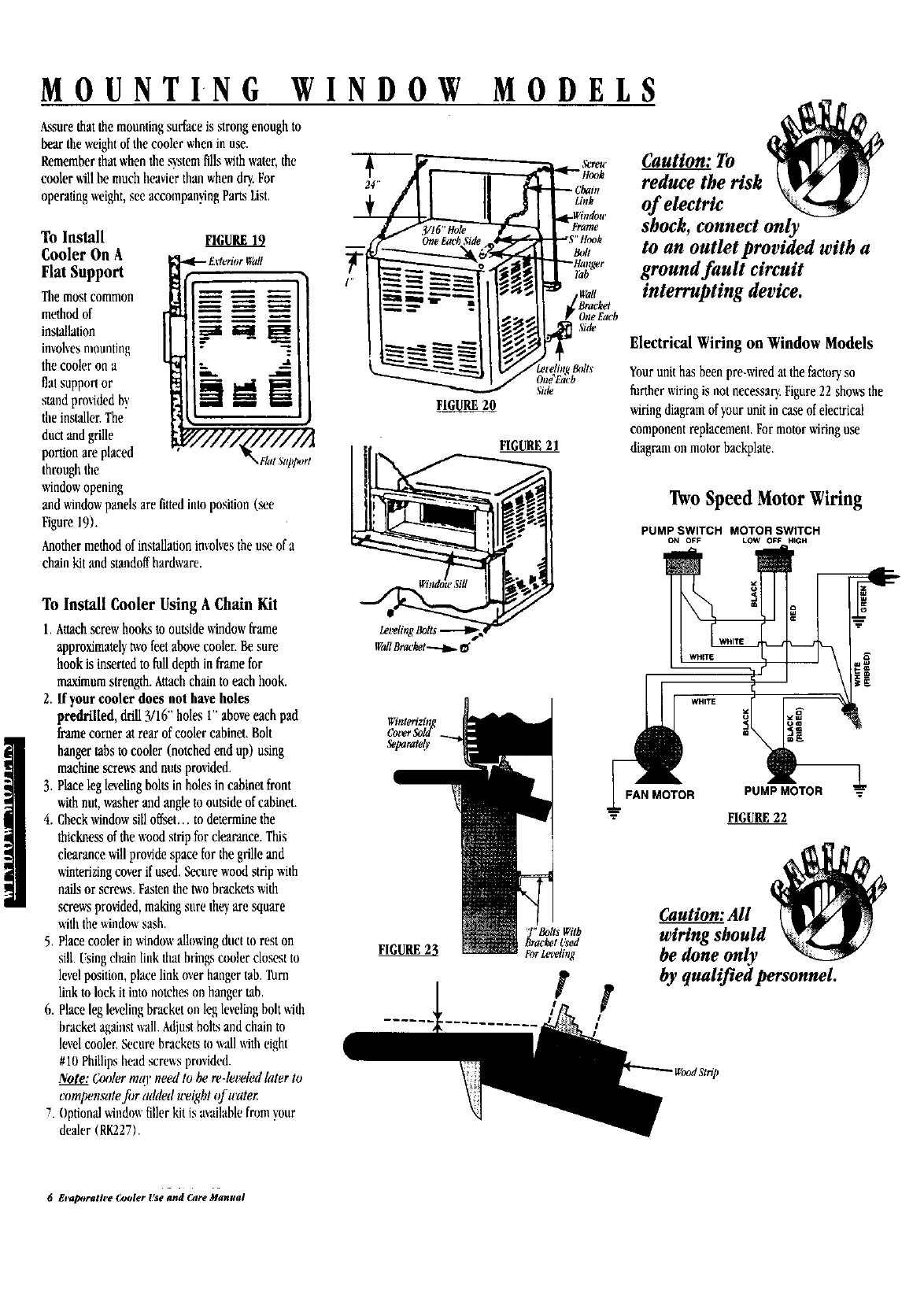
To Install FIGURE19
Cooler On A
Flat Support
Themost commou
method of
installation _ _
involvesmounting "
the cooler on a
fiat support or ,...,t
smnd provided b)
theinstallerThe
ductandgrille
portion are placed ,FlatStq)l_rt
through the
windowopening
and windowpanels are fittedinto position (see
Figure19).
Anothermethodofinstallationinrnlvestheuseofa
chainkitandstandoffhardware.
To Install Cooler Using A Chain Kit
1. Attachscrew hooks to outsidewindow frame
approximatelytwofeet abovecooler. Besure
hook is inserted to fulldepth in frame for
maximumstrength. Attachchain to each hook.
2. If your cooler does not have holes
predrilled, drill 3/16" holes 1"aboveeach pad
frame corner at rear of cooler cabinet. Bolt
hanger tabs to cooler (notched end up) using
machine screws and nuts provided.
3. Placeleg levelingbolts in holes in cabinet front
withnut, washer and angleto outsideof cabinet.
4. Checkwindow sill offset.., to determine the
thicknessof thewood strip for clearance. This
clearance will provide space for thegrille and
winterizingcover if used. Secure wood strip with
nailsor screws. Fastenthe two brackets with
screws provided, making sure they are square
withthe windowsash.
5. Placecooler in windowalluwingduct to rest on
sill. [sing chain liuk that bringscooler closest to
levelposition, place link over hanger tab. Turn
link to lock it into uotches on hanger tab.
6. Place leg levelingbracket nu leg levelingbolt with
bracket againstwall. Adjustbolts and chain to
level cuolen Secure brackets to wall with eight
#10 Phillipshead screws pruvided.
Note: Cooler mt(l' need to be re-let_led later to
compensate filr added weight ¢f water
7Optionalwiudowfiller kit is availablefrum _,_ur
dealer (RK227).
MODELS
_._ Caution: To.
reduce the risk \_
Li,,k of electric "_
Wall
Bracket
One Each
Side
shock, connect only
to an outlet provided with a
ground fault circuit
interrupting device.
Electrical Wiring on Window Models
z,t'eli_tgBolts
)n_Each
Side
F_
FIGURE21
WallBracket _ _;
Winterizin
CoverSoJ_fl
Separatef_
Yourunit has been pre-wired at the factoryso
further wiringis not necessary.Figure22 showsthe
wiring diagram of your unit in case of electrical
component replacement.For motor ;firing use
diagram on motor backplate.
Two Speed Motor Wiring
PUMP SWITCH MOTOR SWITCH
ON OFF LOW OF_=HIGH
r
WHITE
R PUMP MOTOR
I": FIGURE22
'J" BottsWith
8racketL_ed
FIGURE 23 ForLeteling
Caution: All
wiring should
be done only
by qualified personnel.
6 Evaporatil_ Outler Use and _2lre Manual
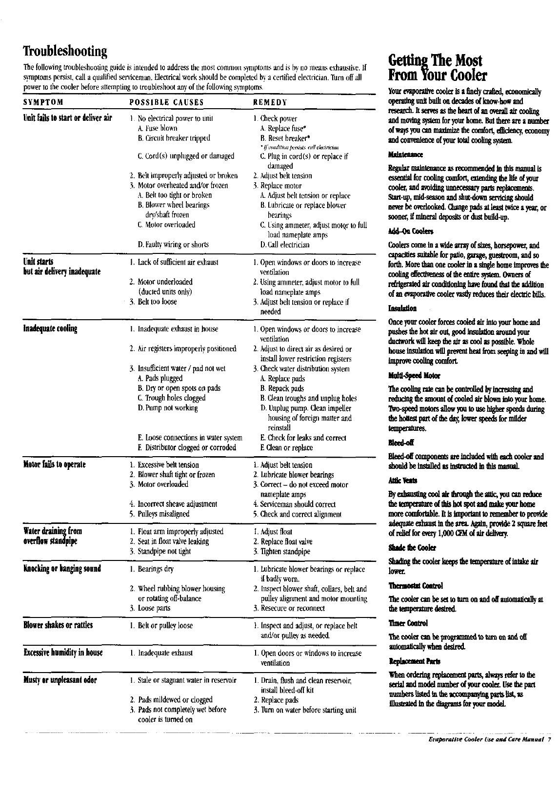
Troubleshooting
Thofullowing troubleshooting guide is intended to address the most common synflttoms and is by uo means exhansBve, If
symptoms persist, call a qualified ,serviceman.Electrical work should b_,compleled by a certified electrician. Turnoffall
power to the cooler before attemptiug to troubleshoot any of the followingsymptoms.
SYMPTOM POSSIBLE CAUSES REMEDY
Unitfailsto startor deliverair 1Noelectric'a]powerto utht
A.Fuseblown
B.Circuitbreakertripped
C,Cord(s) nnplugged or damaged
2. Belt improperlyadjnsted or broken
3. Motoroverheated and/or frnzen
A. Belt too tightor broken
B. Blower wheel bearings
dt)'/shaft frozen
C. Motor overloaded
D. Fanflywiring or shorts
I.Checkpower
ARelflace fuse*
B. Reset breaker*
•Ijmmhtn,I I_,r_l_t_ _all declrtl'Ian
C. Plug in cord(s) or replace if
damaged
2. Mjust belt tensinn
3 Replace motor
A. Adjust beh tension or replace
B.Lubricate or replace blower
bearings
C, Usingammeter, adjust motflr to full
load nameplate amps
D.CaBelectrician
Unitstarts 1. Lackof sufticientairexhaust 1.Openwindowsor doors toincrease
butairdeliveryinadequate ventflaiion
2. Motorunderloaded 2.Usingammeter,adjustmotorto full
(ductedunits only) loadnsttteplateamps
3. Belttooloose 3.Adjustbelttensionor replaceif
needed
Inodequatecoolhtg 1,Openwindowsordoors toincrease
ventilation
2.Adjuslto directair as desiredor
installlowerrestrictionregisters
3.Checkwaterdistributionsystem
A.Replacepads
B. Repackpads
B.Cleantroughsand unplugholes
D, Unplugpump. (;leanimpeller
housingofforeignmatterand
reinstall
I,inadequaleexhanstinhouse
2. Airregisters improperly positioned
3. Insufficientwater/padnot wet
A.Padsplugged
B.Dryoropen spotsonpads
C.Troughholesdogged
D.Pumpnotworking
E. Looseconnections in water system E. Check forleaks and correct
E Distributor clogged or corroded E Clean or replace
Motor _ to operalt l. Excessivebelt tension l. Adjust belt tension
2. Blowershaft tightor frozen 2. Lubricate blower bearings
3. Motor overloaded 3. Correct- do not exceed motor
nameplate amps
4. Incorrectsheave adjustment 4. Serviceman should correct
5, Pulleys misaligned 5. Check and correct alignment
Water_from 1. Float arm improperly adiusted I. Adjustfloat
overflowstandpipe 2. Seat in float valveleaking 2. Replace float valve
3. Standpipe not tight 3. Tightenstandpipe
Kn_iingorbanghtgsound I. Bearings dry, 1. Lubricate blower bearings or replace
iflyadl':',_orn.
2, Wheel rubbingblower housing 2, Inspect blower sh',fft,collars, belt and
or rotating off-balance pulley alignment and motor mounting
3. Loose parts 3. Besecure or reconnect
Blowersbukt$or ra_es I,Belt or pulley loose 1. Inspect and adjust, or replace belt
and/or pdt_ _ o.eeded.
factssivehumidityinhouse 1. Inadequate exhaust 1. Open doors or _ndows to increase
ventilation
Mustyorunpleasantodor I. Staleor stagnantwater in reservoir 1. Drain, flush and clean reservoir,
installbleed-off kit
2. Replace pads
3. Turn on water before starting unit
2. Padsmildewedor clogged
3. Padsnot completelywetbefore
cooleristurnedon
GettingTheMost
FromYourCooler
Yourevuporatizecool_Isafinelyo'.j_d,economlea]ly
upemtngunBImlltoudecadesofImow-howand
rzsearch.Itse_e*astheheartdano_raffaircoo_
andmovingsphereforyourhome.8intbereareanmb_
ofwaysyouc*_tmmmizediecommon,_deacy,economy
swl_eme ofyourfinalcoolings_
M_
gegnbr maintenance_recommendedinthismanualis
_sem_dbr cooll_ comfort,mead_ the_e dyour
cooler,andavoidingtm_ Im_ rephcemems.
Start-up,mid-se*aonandshut-downservicingshould
new beoverlooked.O_mgepadsatleasttwkieayear,or
soona',ffmineraldepositsordustbuild-up.
_tt-Ot C_
CoolerscomeInawldearrayofdzes,horsepowegand
_es _le forZmio,garage,guesU-oom,andso
forth.Morethanonecooler_ at_glehomeimprovesthe
coollngeffealveaessa theemlresystm.Owaersd
r__gerztedZrcon_ionlnghavefoundtlmtbeaddiflon
of_evaporaffvecoolervastlyreducesthordec_cbifls.
Iano]_oo
Onceyourcoolerforcescooled_ Intoyourhomeand
pushesthehutalrout,goodkit_Zlonaroundyour
ductworkwillkeeptheair_ eaolaspns_le.Whole
houseInsu_ionwillprevemheatkomseepinginandwill
improvecoolthgcombtt
M l-s
Thecoo__grutec:mbeconU_liedbyincresstngand
reducingfileamountof cooled airblownIntoyourhome.
'rwo-simedmutorsd_owyoutousehigherspeedsduring
thehoRestpartofthed_,lowerspeedsformilder
tmpermres.
meed-off
Bleed-offo_mponen_are_wl_eacho_olermd
shouldbelnsta_das_m_cd YmthlsmmmL
AtacVel
_tettwramedthlshut_ut andmshzyomhome
mt_ co_lortaSle,ltislr_pomminrmmberB_pro¢,de
adequmn_am _ _ *,r_ t_ain,pro_ Zsourefm
drdld _ en_'yl,OOO_ dalrddiv_.
lower.
T_ eooi_rembe_ tommonandt_ momadeallyat
_ tn_autt_ deglrnt
l'Seec_ canbe_tou_monando_
autom_cdlywheadeaxed,
lepkataemPaers
Whenorderlngrepbcemempm'_,_mysrdettothe
se_dandmo_lnumbetd_ur cooletUsethepan
uumbe_sliged_ _ _cc_mpm_p_s iist,_s
mum_dmO__m_ _ yoosmdeL
Evaporative Cooler Use and Care Manual 7

AdobeAir, Inc.
500 South 15th Street •Phoenix,Arizona 85034
Since Mobedir, Inc follows a policy of continuot_ _¢oduct I_nt, it restores tb¢ tight to
change design and slx_ifications without prior notice or liabilll_
8 Evaporative Cooler Use and Care Manual
