ADRF KOREA ADX-R-78P DAS (Distributed Antenna System) User Manual Rev3 Part2
ADRF KOREA, Inc. DAS (Distributed Antenna System) Rev3 Part2
Contents
- 1. User Manual Rev3_Part1
- 2. User Manual Rev3_Part2
User Manual Rev3_Part2
AdvancedRFTechnologies,Inc. 46
5. MOUNTINGMETHOD
5.1 HeadEnd
5.1.1 RackMount
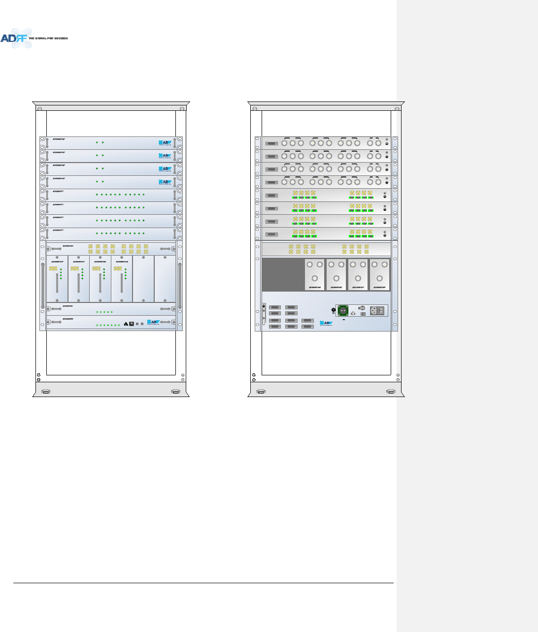
Figure5‐1HERackMount(Front&Rearview)
Expandableupto4OPTs,4BCUsand2AUXCHs
SD
POWER
SOFT FAIL-H
SOFT FAIL-R
HARD FAIL-H
HARD FAIL-R
LINK FAIL-H
LINK FAIL-R
HOST HE VIEW
REMOTE RU VIEW
DL OUTUL IN
HARD FAIL
DL SIG LOW
SOFT FAIL
POWER
DL OUTUL IN
HARD FAIL
DL SIG LOW
SOFT FAIL
POWER
DL OUTUL IN
HARD FAIL
DL SIG LOW
SOFT FAIL
POWER
DL OUTUL IN
HARD FAIL
DL SIG LOW
SOFT FAIL
POWER
UL1 UL2 UL3 UL4
DL1 DL2 DL3 DL4
UL5UL6UL7UL8
DL5DL6DL7DL8
LD FAIL5-8 LINK5 LINK6 LINK7 LINK8LD FAIL1-4 LINK1 LINK2 LINK3 LINK4POWER
SOFT FAILPOWER
POWER
CHG STS
LOW BATT
AC FAIL
DC FAIL
LD FAIL5-8 LINK5 LINK6 LINK7 LINK8LD FAIL1-4 LINK1 LINK2 LINK3 LINK4POWER
LD FAIL5-8 LINK5 LINK6 LINK7 LINK8LD FAIL1-4 LINK1 LINK2 LINK3 LINK4POWER
LD FAIL5-8 LINK5 LINK6 LINK7 LINK8LD FAIL1-4 LINK1 LINK2 LINK3 LINK4POWER
SOFT FAILPOWER
SOFT FAILPOWER
SOFT FAILPOWER
SD
DL IN UL OUT
DPX
DL IN UL OUT
DPX
DL IN UL OUT
DPX
DL IN UL OUT
DPX
UL5UL6UL7UL8
DL5DL6DL7DL8
UL1UL2UL3UL4
DL1DL2DL3DL4
OPT 1 OPT 2
OPT 3 OPT 4
BAND COM 1 BAND COM 2
BAND COM 3 BAND COM 4
AUX_CH 1
AUX_CH 2
OFF
VHF UL 2 UL O UT 2 VHF DL 2 DL IN 2
LINK 8 LINK 7 LINK 6 LINK 5
VHF UL 1 UL OUT 1 VHF DL 1 DL IN 1
LINK 4 LINK 3 LINK 2 LINK 1
OPT
VHF UL 2 UL O UT 2 VHF DL 2 DL IN 2
LINK 8 LINK 7 LINK 6 LINK 5
VHF UL 1 UL OUT 1 VHF DL 1 DL IN 1
LINK 4 LINK 3 LINK 2 LINK 1
OPT
VHF UL 2 UL O UT 2 VHF DL 2 DL IN 2
LINK 8 LINK 7 LINK 6 LINK 5
VHF UL 1 UL OUT 1 VHF DL 1 DL IN 1
LINK 4 LINK 3 LINK 2 LINK 1
OPT
VHF UL 2 UL O UT 2 VHF DL 2 DL IN 2
LINK 8 LINK 7 LINK 6 LINK 5
VHF UL 1 UL OUT 1 VHF DL 1 DL IN 1
LINK 4 LINK 3 LINK 2 LINK 1
OPT
DL IN 3
BAND COM
CH3 CH2 CH1 SUM
DPX 3 UL OUT 3 DL IN 2 DPX 2 UL OUT 2 DL IN 1 DPX 1 UL OUT 1 DL OUT UL IN
DL IN 3
BAND COM
CH3 CH2 CH1 SUM
DPX 3 UL OUT 3 DL IN 2 DPX 2 UL OUT 2 DL IN 1 DPX 1 UL OUT 1 DL OUT UL IN
DL IN 3
BAND COM
CH3 CH2 CH1 SUM
DPX 3 UL OUT 3 DL IN 2 DPX 2 UL OUT 2 DL IN 1 DPX 1 UL OUT 1 DL OUT UL IN
DL IN 3
BAND COM
CH3 CH2 CH1 SUM
DPX 3 UL OUT 3 DL IN 2 DPX 2 UL OUT 2 DL IN 1 DPX 1 UL OUT 1 DL OUT UL IN
OFF
BATTERY
INSTALL
BATTER Y
BATTERY
AC SELECT OFF/ONAC IN
S/WOFF ON
24V 1A
AdvancedRFTechnologies,Inc. 47
5.1.2 WallMount
Figure5‐2HEWallMount(TopView)
Expandableupto3units(OPT,BCU)ormax3U(132mm)
‐ ODURackorBCUwillbestackedupabovebasic19”HEchassiswhichincludesNMS,RFU,PSUandCHC
POWER
SOFT FAIL-H
SOFT FAIL-R
HARD FAIL-H
HARD FAIL-R
LINK FAIL-H
LINK FAIL-R
POWER
CHG STS
LOW BATT
AC FAIL
DC FAIL
AdvancedRFTechnologies,Inc. 48
5.2 RemoteUnit
5.2.1 RackMount
Figure5‐3RURackMount(Frontview)
POWER
CHG-STS
LOW BATT
AC FAIL
DC FAIL
AdvancedRFTechnologies,Inc. 49
5.2.2 WallMount
5.2.2.1 RemoteUnitusingRUChassis(ADX‐R‐CHA‐30)
Wallmountbracketsattachedtotheindividualremotemodulesmustberemovedbeforeslidingtheremote
modulesintotheRUChassis.
Figure5‐419”Shelftype‐RUWallMount(Topview)
5.2.2.2 IndividualRemoteModule
Remotemodulescanbemountedusingtheattachedmountingbracketthatshipswiththeunit.
Figure5‐5RemoteModuleWallMount(Topview)
SERVER
UL1 UL2 UL3 UL4
DL1 DL2 DL3 DL4
M-DL
M-UL
CPL(-30dB)
E-DL
E-UL
VHF DL VH F UL
EF-DL IN EF-DL OUT
EF-UL INEF-UL OUT
POWER
CHG-STS
LOW BATT
AC FAIL
DC FAIL
DL IN
SERVER
CPL(-30dB)
UL OUT
EF-DL OUT EF-DL IN EF-UL IN EF-UL OUT
DL IN
SERVER
CPL(-30dB)
UL OUT
EF-DL OUT EF-DL IN EF-UL IN EF-UL OUT
DL IN
SERVER
CPL(-30dB)
UL OUT
EF-DL OUT EF-DL IN EF-UL IN EF-UL OUT
DL IN
SERVER
CPL(-30dB)
UL OUT
EF-DL OUT EF-DL IN EF-UL IN EF-UL OUT
DL4 DL3 DL2 DL1 ADX-R -4WS UL4 UL3 UL2 UL1
M-ULM-DL
DL IN
SERVER
CPL(-30dB)
UL OUT
EF-DL OUT EF-DL IN EF-UL IN EF-UL OUT
AdvancedRFTechnologies,Inc. 50
6. INSTALLATION
6.1 Pre‐InstallationInspection
PleasefollowtheseproceduresbeforeinstallingADXequipment:
o Verifythenumberofpackagesreceivedagainstthepackinglist.
o Checkallpackagesforexternaldamage;reportanyexternaldamagetotheshippingcarrier.If
thereisdamage,ashippingagentshouldbepresentbeforeyouunpackandinspectthecontents
becausedamagecausedduringtransitistheresponsibilityoftheshippingagent.
o Openandcheckeachpackageagainstthepackinglist.Ifanyitemsaremissing,contactADRF
customerservice.
o Ifdamageisdiscoveredatthetimeofinstallation,contacttheshippingagent.
o VerifytheACvoltagewithDVM(Voltmeter),thenselecttheeither110Vor220VACusingthe
selectionswitchlocatedattherearofHEandRUPSU.TheADXshipswiththeACselection
switchsettothe110Vposition.IncorrectACselectioncandamagetheADXequipment.
6.2 ADXDASInstallationProcedure
6.2.1 HEInstallationProcedure
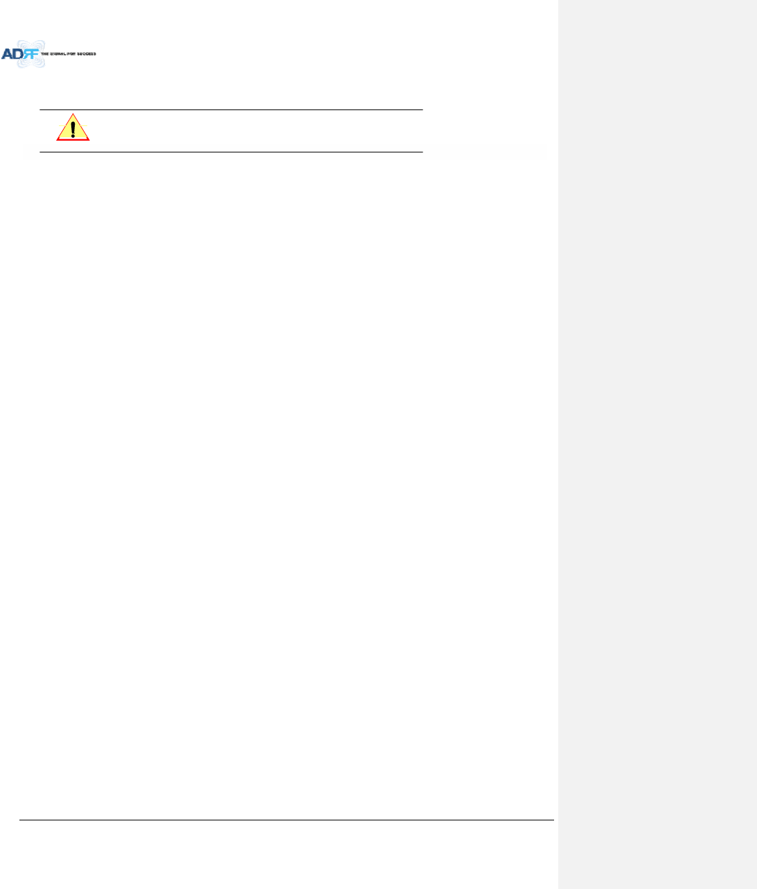
CAUTION: ADXDASHEshouldbeinstalledinsidebuildingonly.
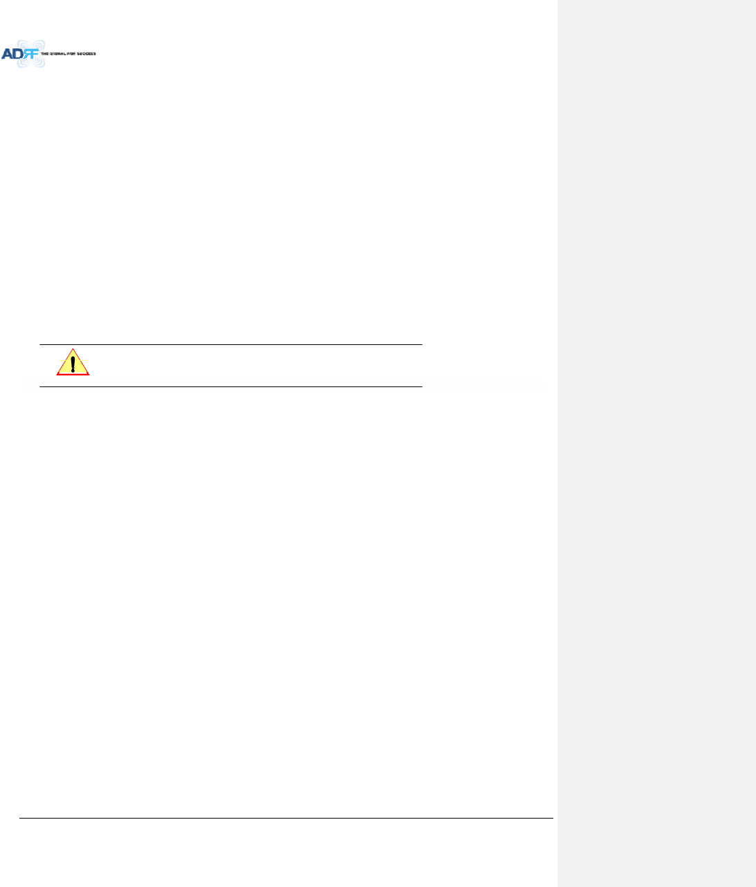
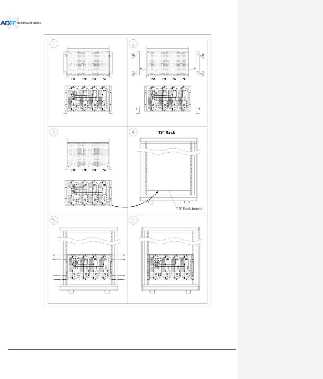
6.2.1.1 InstallingaADXDASHEinarack
TheADXHEchassismountsinastandard19”(483mm)equipmentrack.Allowclearanceof3”(76mm)atthe
frontandrear,and2”(51mm)onbothsidesforaircirculation.Notoporbottomclearanceisrequired.
Consideration:
‐ Eightmountingholesarelocatedon4cornersofADXHEtoattachittothe19”rack.TheADXHEmustbe
securelyattachedtoarackthatcansupporttheweightoftheADX.
Mountprocedure
‐ ThefollowingstepsshouldbefollowedwhilemountingtheADXHE
DetachthewallmountbracketassembledlocatedatthebaseoftheADX‐HEchassis
VerifythattheHEandMountingholesareingoodcondition
SettheADXDASHEagainstthe19”rackandsecuretheunitwithscrews
VerifythatADXHEissecurelyattached
ConnecttheGNDcable
ConnecttheRFcable
ConnectthePower
ConnecttheOpticcable
AdvancedRFTechnologies,Inc. 51
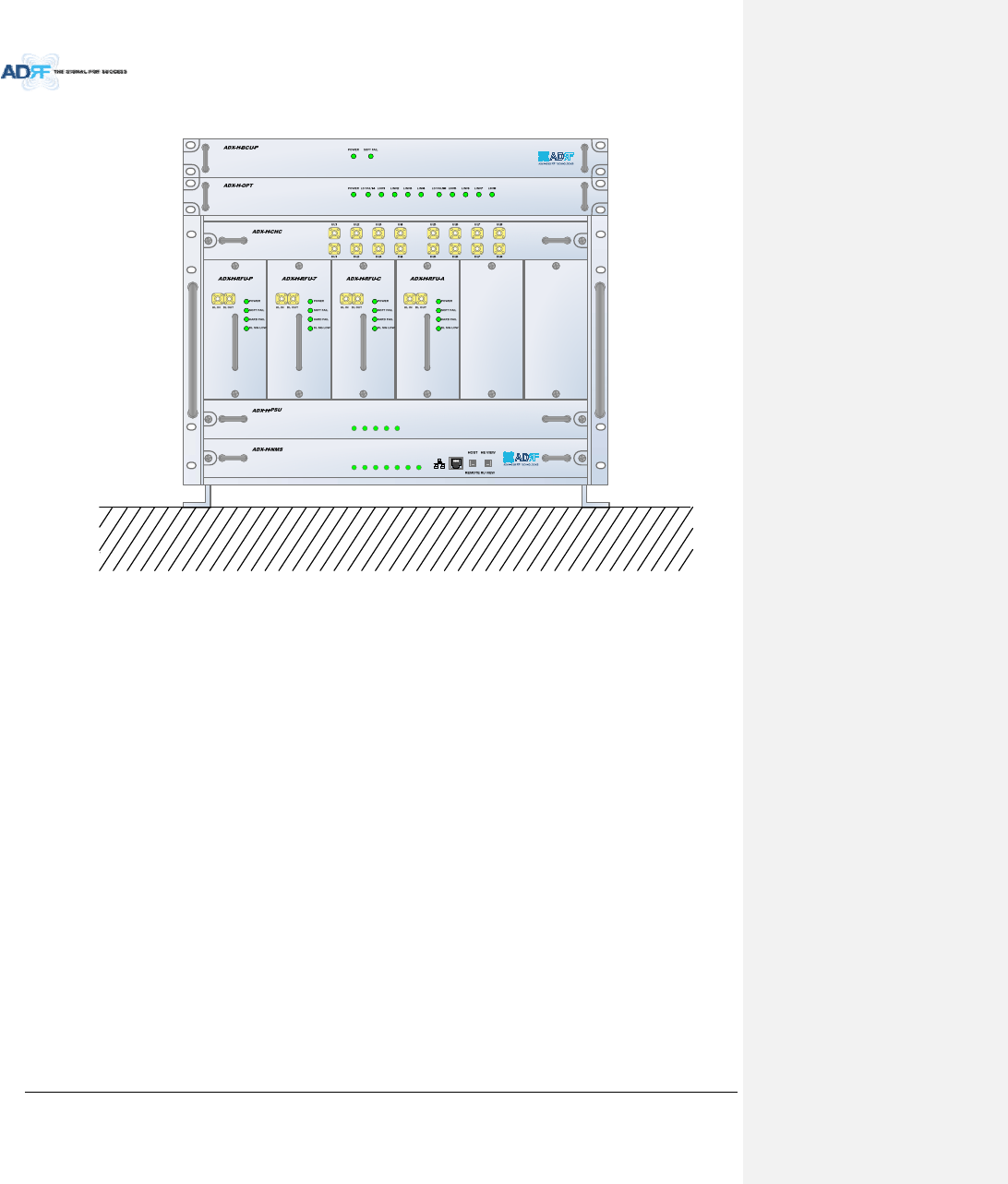
Figure6‐1ADXHE19”RackMountInstructions
AdvancedRFTechnologies,Inc. 52
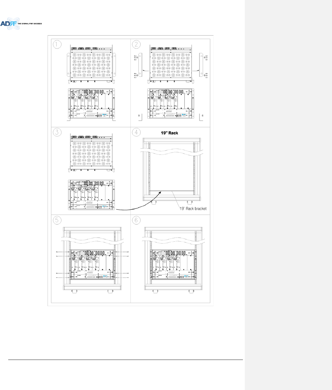
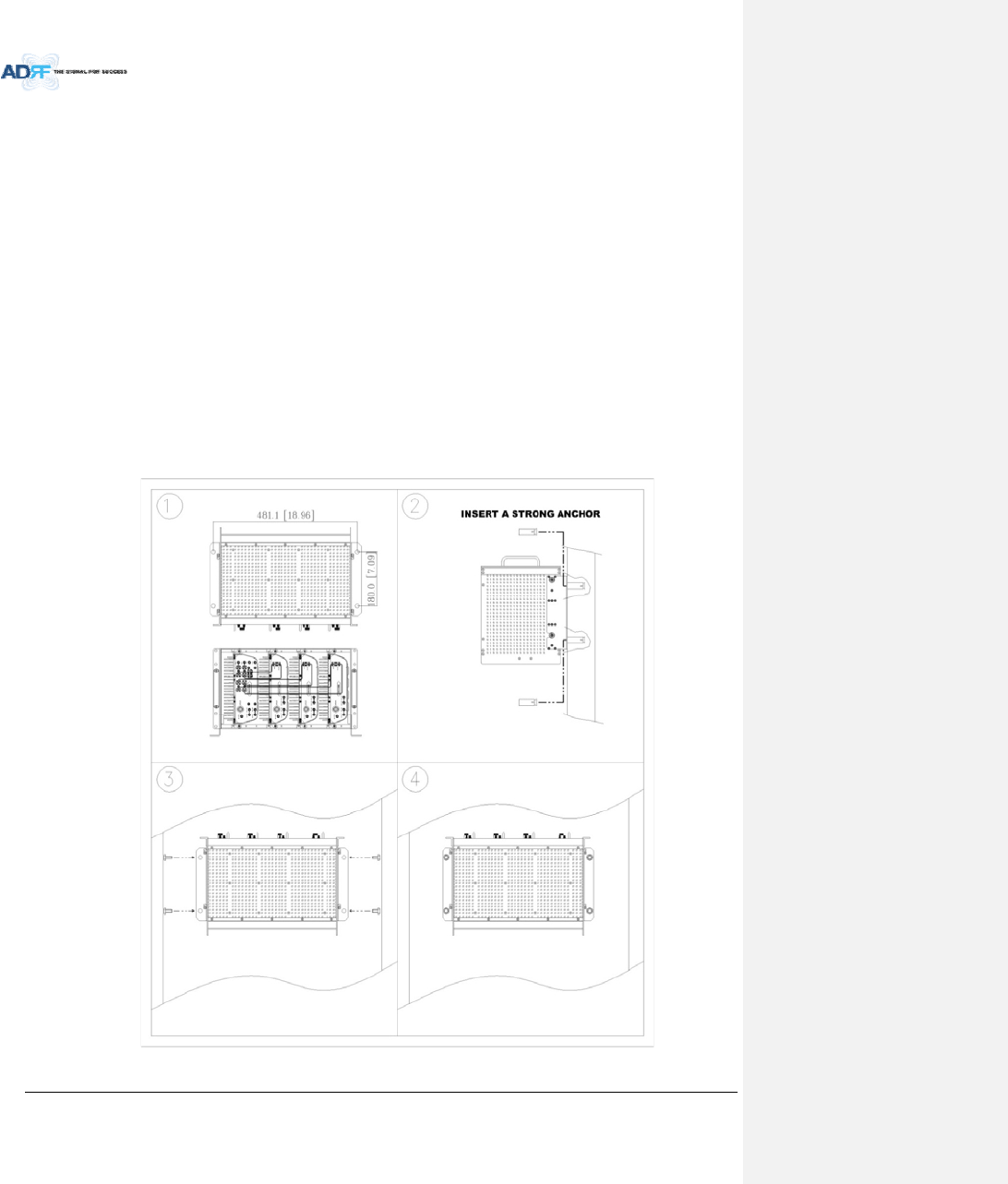
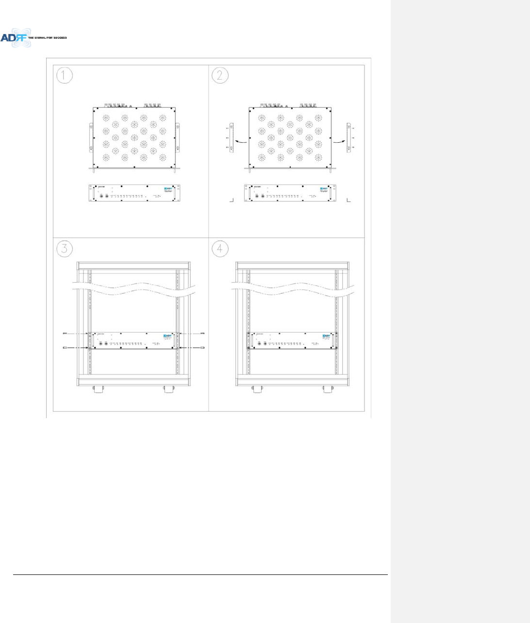
6.2.1.2 WallmountingtheADXDASHE
IftheADXHEchassisisbeingmountedtoawall,thenallowclearanceofatleast17”(430mm)onthetop
(frontsideofHE)and2”(51mm)onthebottom(rearsideofHE)and2”(51mm)onbothsidesandfrontforair
circulation.
Mountprocedure
‐ ThefollowingstepsshouldbefollowedwhenwallmountingtheADXHE
VerifythattheHEandMountingholeareingoodcondition
PlacetheADXHEagainstthewallandmarkofthemountingholes
Drillholes(4holes,18Φmm,50mmdepth)intheinstallationsurfaceandinserttheanchorbolts
BolttheADXHEtothewall
MakesuretheADXHEissecurelyattached
ConnecttheGNDcable
ConnecttheRFcable
ConnectthePower
ConnecttheOpticcable
Figure6‐2ADXHEWallMountInstructions
AdvancedRFTechnologies,Inc. 53
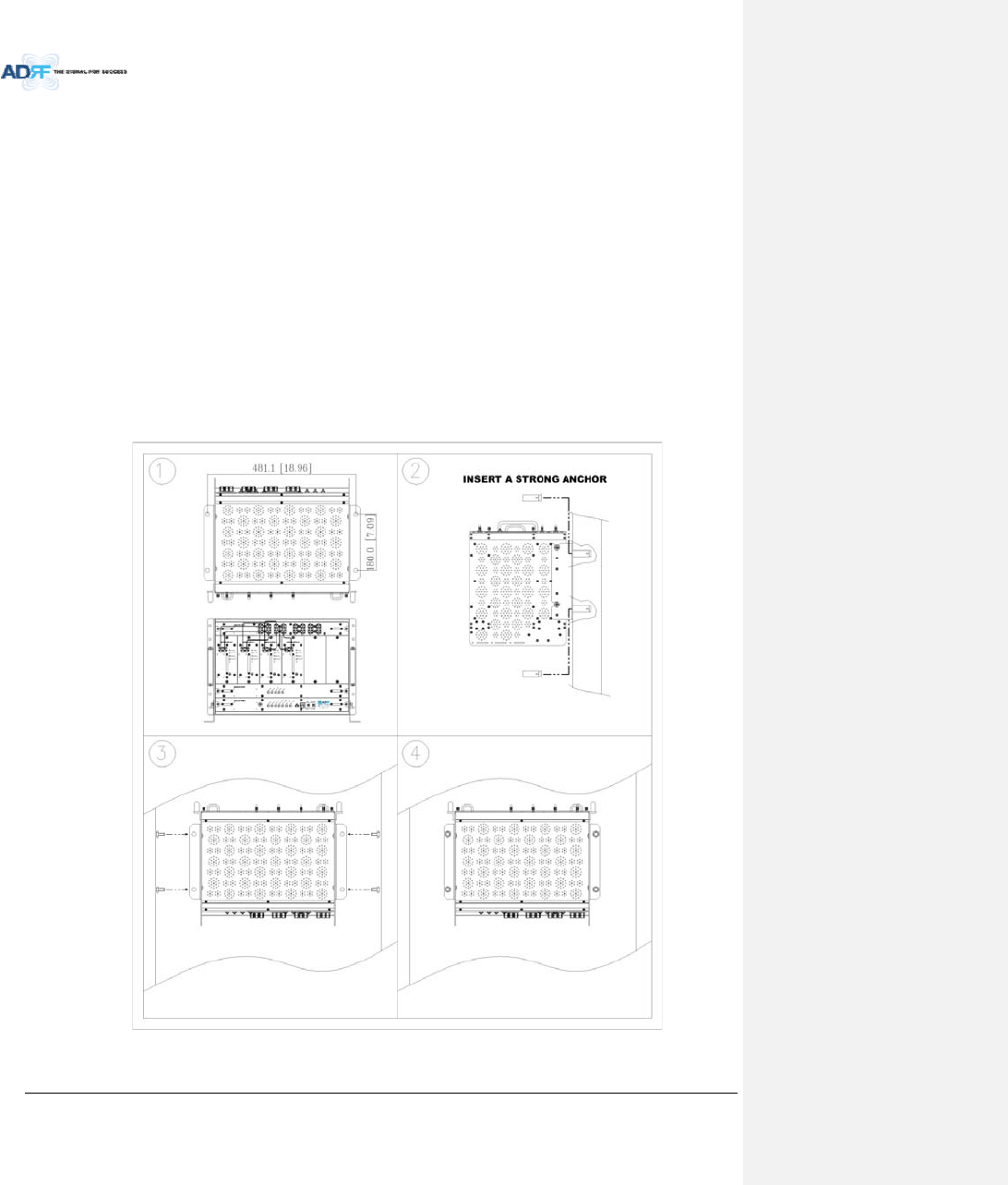
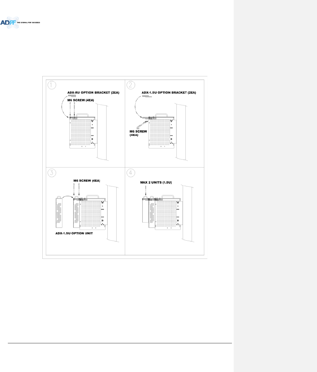
6.2.1.2.1 InstallingaddedracktypemodulesintobasicHEchassis
AdditionalmodulessuchastheADX‐H‐RACK‐ODUandADX‐H‐BCUcanbemountedtotheChassis(ADX‐H‐CHA)
usingtheincludedmountingbracketsthatcomewiththeadd‐onmodules.
Amaximumofupto3addonmodules(OPT,BCU)canbemountedtothechassis
‐ ODURackorBCUwillbestackedupabovebasic19”HEchassiswhichincludesNMS,RFU,PSUandCHC
Figure6‐3WallMountInstructionsforADX‐HEadded1UUnit

AdvancedRFTechnologies,Inc. 54
6.2.2 RUInstallationProcedure
CAUTION: ADXDASRUshouldbeinstalledinsidebuildingonly.
6.2.2.1 InstallingaADXDASRUinarack
IftheADXRUchassisisbeingwallmountedthenallowclearanceof3”(76mm)frontandrear,and2”(51mm)
onbothsidesforaircirculation.Notoporbottomclearanceisrequired.
WhenADXDASRUmountsinastandard19”equipmentrack,rackorwalltypefanisneededforheat
dissipation.Theracktypefan(ADX‐R‐FAN)musthaveatleast1.75"ofclearance.
Consideration:
‐ Eightmountingholesarelocatedon4cornersofADXRUtoattachittothe19”rack.TheADXRUmustbe
securelyattachedtosupporttheweightoftheADX‐RUunits.
Mountprocedure
‐ ThefollowingstepsshouldbefollowedwhilemountingtheADX‐RUunits
DetachthewallmountbracketlocatedatthebaseoftheADX‐RUchassis
VerifythattheRUandMountingholeareingoodcondition
ScrewtheADXDASRUtothe19”rack
MakesuretheADXRUissecurelyattached
ConnecttheGNDcable
ConnecttheRFcable
ConnectthePower
ConnecttheOpticcable
AdvancedRFTechnologies,Inc. 55
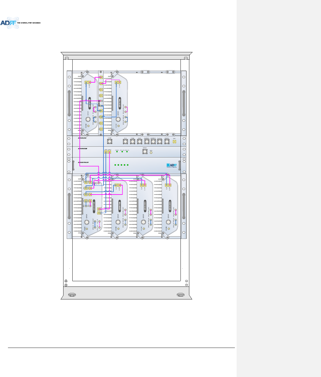
Figure6‐4ADX‐RU19”RackMountInstructions
AdvancedRFTechnologies,Inc. 56
6.2.2.2 WallmountingtheADXDASRU
IftheADXRUchassisisbeingmountedtoawall,thenallowclearanceofatleast16”(406mm)onthetop
(frontsideofRU),2”(51mm)onthebottom(rearsideofRU)and2”(51mm)onbothsidesandfrontforair
circulation.
Mountprocedure
‐ ThefollowingstepsshouldbefollowedwhilemountingtheADXRU
VerifythattheRUandMountingholeareingoodcondition
PlacetheRUchassisupagainstthewallandmarkoffthemountingholes
Drillholes(4holes,18Φmm,50mmdepth)intheinstallationsurfaceandinserttheanchorbolts
BolttheRUchassistothewall
InstalltheindividualSub‐RUinsideofthechassis
MakesuretheRUchassisissecurelyattached
ConnecttheRFcable
ConnecttheAntennacable
ConnectthePower
ConnecttheOpticcable
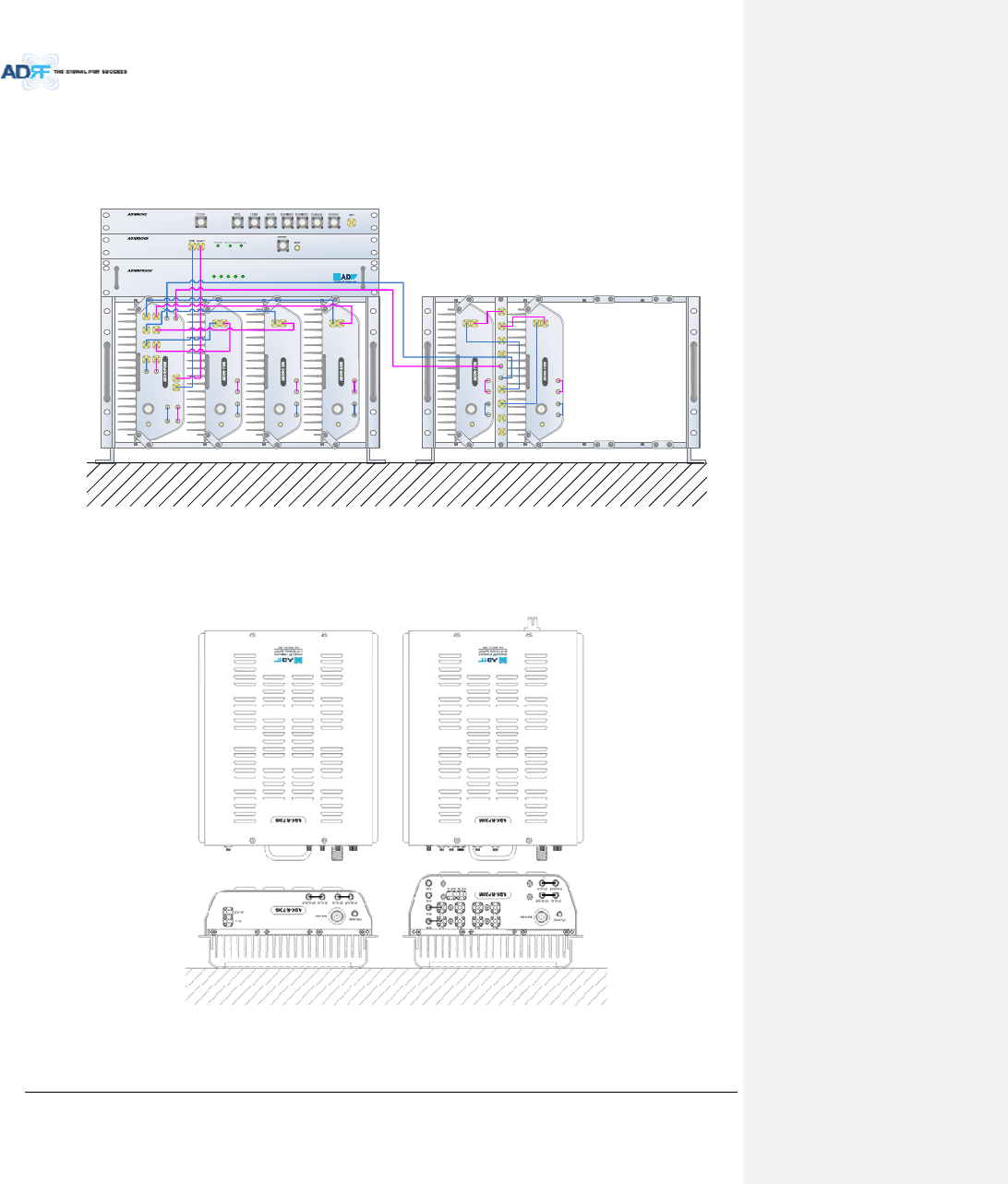
Figure6‐5ADX‐RUWallMountInstructions
AdvancedRFTechnologies,Inc. 57
6.2.2.2.1 InstallingaddedracktypemodulesintobasicHEchassis
AdditionalmodulessuchastheADX‐R‐CHC(channelcombiner)andADX‐R‐PSU(powersupplyunit)canbe
mountedtotheChassis(ADX‐R‐CHA)usingtheincludedmountingbracketsthatcomewiththeadd‐onmodules.
Amaximumofupto2addonmodules(ADX‐R‐CHCandADX‐R‐PSU)canbemountedtothechassis.
‐ ADX‐R‐PSUorADX‐R‐CHCwillbestackedupabovebasic19”RUchassiswhichholdstheMaster/SlaveRU
units.
Figure6‐6WallMountInstructionsforADX‐RUadded1.5UUnit
AdvancedRFTechnologies,Inc. 58
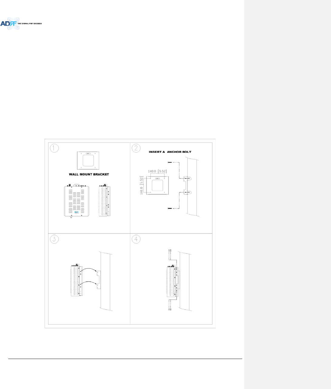
6.2.2.3 WallmountinganADXRemoteModule
Mountprocedure
‐ ThefollowingstepsshouldbefollowedwhilemountingtheRemoteModule
VerifythattheRUandMountingholeareingoodcondition
SeparatethewallmountbracketfromtheSub‐RU
Placedthewallmountbracketagainstthewallandmarkoffthemountingholes
Drillholes(4holes,6Φmm)intheinstallationsurfacetheninserttheenclosedanchorbolts
Boltthemountingbrackettothewall
InstalltheSub‐RUtothemountingbracket
FastentheSub‐RUtothemountingbracketusingtheincludedscrews
VerifythattheRemoteModuleissecurelyattached
ConnecttheAntennacable
ConnectthePower
ConnecttheOpticcable(ifapplicable)
Figure6‐7RemoteModuleWallMountInstructions
AdvancedRFTechnologies,Inc. 59
6.2.3 ADX‐H‐OEUInstallationProcedure
CAUTION: ADX‐H‐OEUshouldbeinstalledinsidebuildingonly.
6.2.3.1 InstallingaADX‐H‐OEUinaRack
TheADX‐H‐OEUmountsinastandard19”(483mm)equipmentrack.Allowclearanceof3”(76mm)frontand
rear,and2”(51mm)onbothsidesforaircirculation.Notoporbottomclearanceisrequired.
Consideration:
‐ Fourmountingholesarelocatedon4cornersofADX‐H‐OEUtoattachittothe19”rack.TheADX‐H‐OEU
mustbesecurelyattachedtosupporttheweightoftheunit.
Mountprocedure
‐ ThefollowingstepsshouldbefollowedwhilemountingtheADX‐H‐OEU
DetachthewallmountbracketslocatedatthebaseoftheADX‐H‐OEU
VerifythattheOEUandmountingholeareingoodcondition
ScrewtheADX‐H‐OEUtothe19”rack
MakesuretheADX‐H‐OEUissecurelyattached
ConnecttheGNDcable
ConnecttheRFcable
ConnectthePower
ConnecttheOpticcable
AdvancedRFTechnologies,Inc. 60
Figure6‐8ADX‐H‐OEURackMountInstructions
AdvancedRFTechnologies,Inc. 61
6.2.3.2 WallmountingtheADX‐H‐OEU
Mountprocedure
‐ ThefollowingstepsshouldbefollowedwhilemountingtheADX‐H‐OEU
VerifythattheOEUandMountingholeareingoodcondition
Drillholes(4holes,6Φmm)intheinstallationsurfacetheninserttheenclosedanchorbolts
SettheADX‐H‐OEUagainstthewall
MakesuretheOEUissecurelyattached
ConnecttheRFcable
ConnecttheAntennacable
ConnectthePower
ConnecttheOpticcable
Figure6‐9ADX‐H‐OEUWallMountInstructions
AdvancedRFTechnologies,Inc. 62
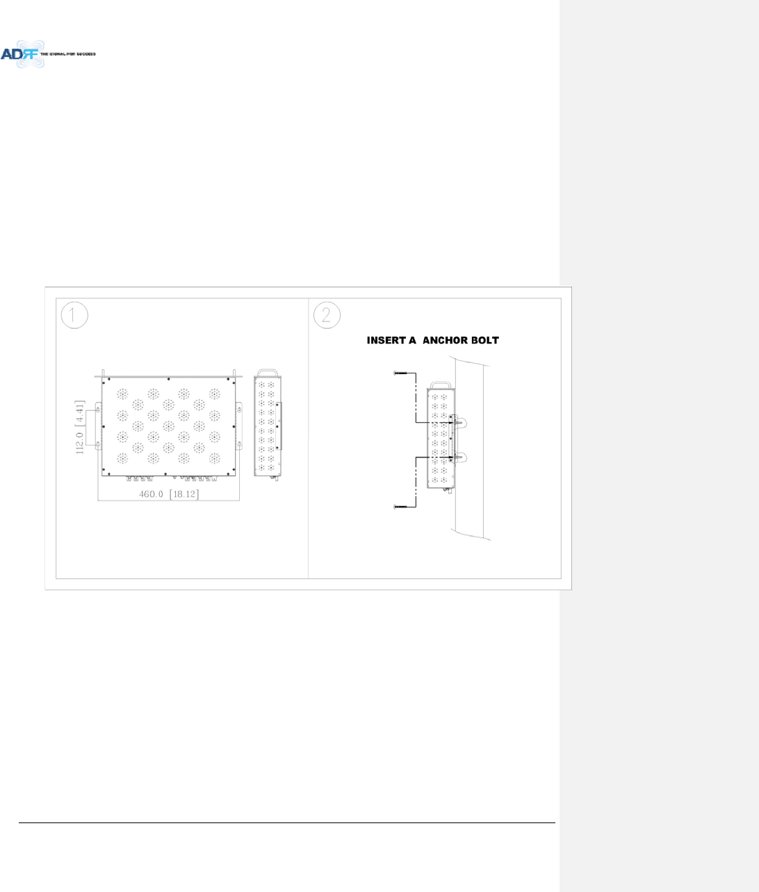
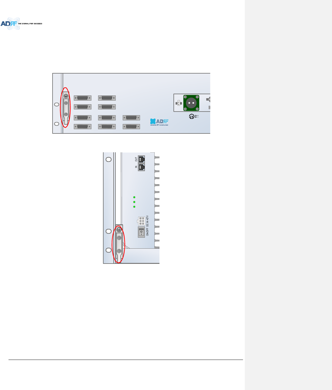
6.3 Grounding
Agroundcableisincludedinthebox.ThegroundingterminalsarelocatedattherearoftheADXHEandRU.
Thegroundingcableshouldbeproperlyconnectedbeforepoweringontheequipment.
Figure6‐10GroundCableConnection(HErearside)
Figure6‐11GroundCableConnection(RUrearside)
OPT 1 OPT 2
OPT 3 OPT 4
BAND COM 1 BAND COM 2
BAND COM 3 BAND COM 4
AUX_CH 1
AUX_CH 2
BATTERY
INSTALL
BATTERY 24V BA
T
A
C
POWER
SOFT FAIL
HARD FAIL
AdvancedRFTechnologies,Inc. 63
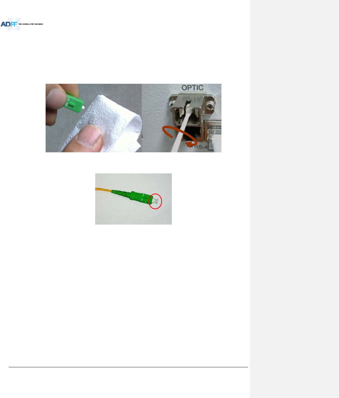
6.4 OpticPortCleaning
Werecommendcleaningopticconnectorusingadryopticalcleaningswabortissueinadryenvironmentas
needed.Werecommendcleaningtheopticconnectorsonlyiftheexpectedopticlossishigherthantheloss
reportedintheWeb‐GUIby1.5dBo.(Figure6‐12)
Whenopticconnectorarenotinuse,theportshouldbecoveredwithaprotectivedustcap.(Figure6‐13)
Figure6‐12OpticConnectorCleaning(left)andOpticPortCleaning(right)
Figure6‐13SC/APCOpticConnectorDustCap

AdvancedRFTechnologies,Inc. 64
7. WARRANTYANDREPAIRPOLICY
7.1 GeneralWarranty
TheADXcarriesaStandardWarrantyperiodoftwo(2)yearsunlessindicatedotherwiseonthepackageorin
theacknowledgmentofthepurchaseorder.
7.2 LimitationsofWarranty
Yourexclusiveremedyforanydefectiveproductislimitedtotherepairorreplacementofthedefective
product.AdvancedRFTechnologies,Inc.mayelectwhichremedyorcombinationofremediestoprovideinitssole
discretion.AdvancedRFTechnologies,Inc.shallhaveareasonabletimeafterdeterminingthatadefectiveproduct
existstorepairorreplacetheproblemunit.AdvancedRFTechnologies,Inc.warrantyappliestorepairedor
replacedproductsforthebalanceoftheapplicableperiodoftheoriginalwarrantyorninetydaysfromthedateof
shipmentofarepairedorreplacedproduct,whicheverislonger.
7.3 LimitationofDamages
Theliabilityforanydefectiveproductshallinnoeventexceedthepurchasepriceforthedefectiveproduct.
7.4 NoConsequentialDamages
AdvancedRFTechnologies,Inc.hasnoliabilityforgeneral,consequential,incidentalorspecialdamages.
7.5 AdditionalLimitationonWarranty
AdvancedRFTechnologies,Inc.standardwarrantydoesnotcoverproductswhichhavebeenreceived
improperlypackaged,altered,orphysicallydamaged.Forexample,brokenwarrantyseal,labelsexhibiting
tampering,physicallyabusedenclosure,brokenpinsonconnectors,anymodificationsmadewithoutAdvancedRF
Technologies,Inc.authorization,willvoidallwarranty.
7.6 ReturnMaterialAuthorization(RMA)
NoproductmaybereturneddirectlytoAdvancedRFTechnologies,Inc.withoutfirstgettinganapprovalfrom
AdvancedRFTechnologies,Inc.Ifitisdeterminedthattheproductmaybedefective,youwillbegivenanRMA
numberandinstructionsinhowtoreturntheproduct.Anunauthorizedreturn,i.e.,oneforwhichanRMAnumber
hasnotbeenissued,willbereturnedtoyouatyourexpense.Authorizedreturnsaretobeshippedtotheaddress
ontheRMAinanapprovedshippingcontainer.Youwillbegivenourcourierinformation.Itissuggestedthatthe
originalboxandpackagingmaterialsshouldbekeptifanoccasionariseswhereadefectiveproductneedstobe
shippedbacktoAdvancedRFTechnologies,Inc.TorequestanRMA,pleasecall(800)313‐9345orsendanemailto
techsupport@adrftech.com.
AdvancedRFTechnologies,Inc. 65
8. WEB‐GUI
8.1 Web‐GUISetup
TheWeb‐GUIallowstheusertocommunicatewiththeDASsystemeitherlocallyorremotely.Toconnectto
theDASsystemlocally,youwillneedalaptopwithanEthernetportandaRJ‐45crossovercable.Toconnectto
theDASsystemremotely,youwillneedtohaveanactiveinternetconnectionandtheADXsystemmusthaveand
externalmodemboxconnectedtotheADX.
8.1.1 DASsystem/PCConnectionUsingWeb‐GUI
VerifythatyourLocalAreaConnectionissettoObtainanIPaddressautomaticallyundertheInternetProtocol
(TCP/IP)properties
‐ Ifyouareconnectingtotheunitremotely(useofamodem),thenskipthisandnextstep.
ConnecttheRJ‐45crossovercablebetweenthelaptop’sEthernetportandtherepeater’sEthernetport
LaunchanInternetBrowser
TypethefollowingIPaddressintotheaddressbarofMicrosoftInternetExplorer:http://192.168.63.1
‐ Ifyouareconnectingtotheunitremotely,thentypetheIPaddressofthemodemtoconnecttotheunit
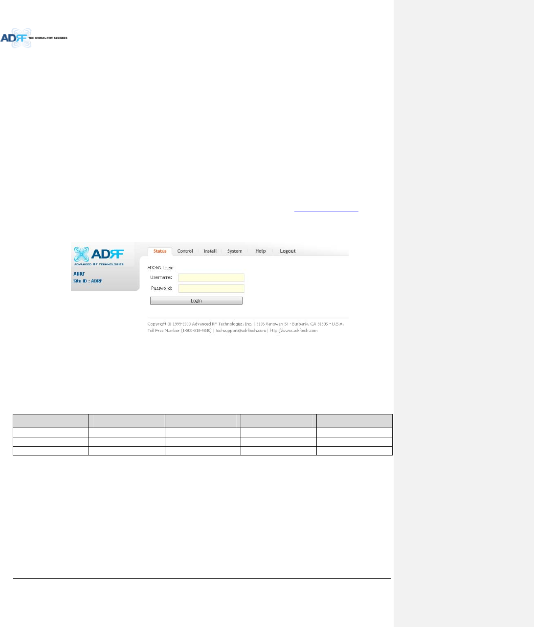
Thefollowingloginscreenwillappear:
Figure8‐1Loginscreen
IfyouarenottheAdministrator,pleasetypeinyourassignedusername&passwordwhichyoushouldhave
receivedfromtheAdministrator.
Table8‐1AccountInformationforLogin
AccounttypeShowitemsControlItemsDefaultIDDefaultPassword
AdministratorallItems allitems admin admin
Userrestricteditemsrestricteditems adrf adrf
Guestrestricteditemsread‐only guest guest
AdvancedRFTechnologies,Inc. 66
8.2 Administrator/UserMode
8.2.1 Common
8.2.1.1 NavigationtreeLock/Unlock
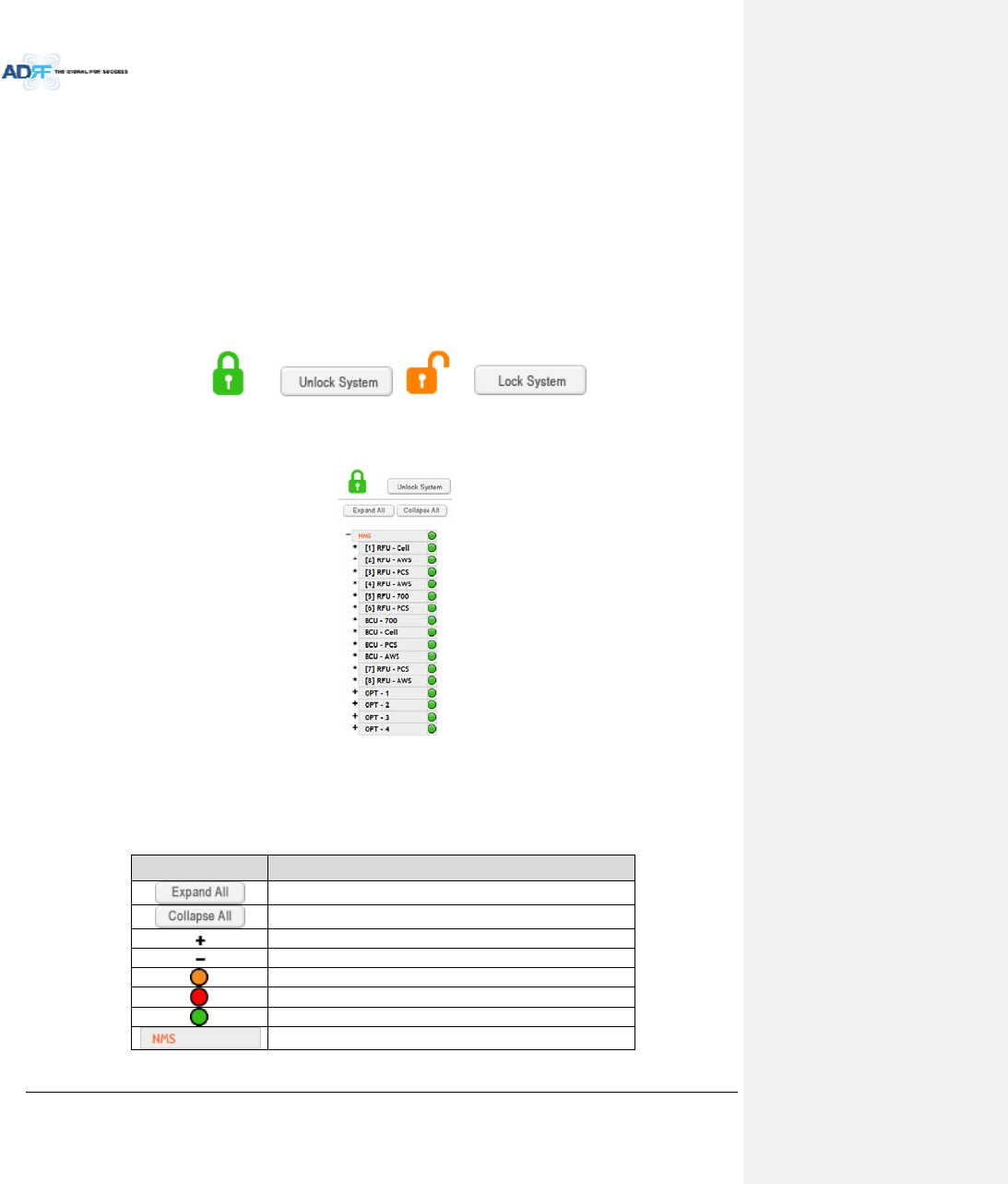
Whenthesystemis“Locked”,agreenlockiconwillappearabovethenavigationtree.Whenthesystemis
locked,newdevicescannotbeadded.Anydevicesaddedtothesystemwhenthesystemis“Locked”willnotbe
detectedbytheNMS.Afterasystemhasbeencommissionedproperly,thesystemshouldbeleftinthe“Locked”
position.Tounlockthesystem,clickonthe“UnlockSystem”buttontotherightoftheicon.
Whenthesystemis“Unlocked”,anorangeiconwillappearabovethenavigationtree.Whenthesystemis
unlocked,newdevicesaddedtothesystemwillbeautomaticallydetected.Oncethenewhardwareappearsinthe
systemtree,thenthesystemcanbelocked.Tolockthesystem,clickonthe“LockSystem”buttontotherightof
theicon.
Figure8‐2NavigationtreeLock/Unlock
8.2.1.2 NavigationTree
Figure8‐3Navigationtree
ThenavigationtreelocatedonthelefthandsideoftheWeb‐GUIallowstheusertoswitchbetweenthe
variousmodulesthatareconnectedtothesystem.
Table8‐2Navigationtree
ParametersDescription
Expands theentirenavigationtree
Collapses theentirenavigationtree
Themodulehastheexpandablesubordinate modules
Thebranchiscurrentlyexpanded
Themodulehassoftfailalarm
Themodulehashardfailalarm
Themodulehasnoalarms(normal)
Theselectedmodulewillhaveorangecoloredtext
AdvancedRFTechnologies,Inc. 67
8.2.1.3 PowerStatus
Displaythepowersourcethatiscurrentlybeingused.
Table8‐3PowerSupplyStatus
InputPowerStatusDisplayImage
AC
Battery
8.2.1.4 CommissioningStatus
Displaywhetherornotthemodulehassuccessfullybeencommissioned.
Table8‐4CommissioningICON
StatusDisplayImage
Commissioned
Not‐Commissioned
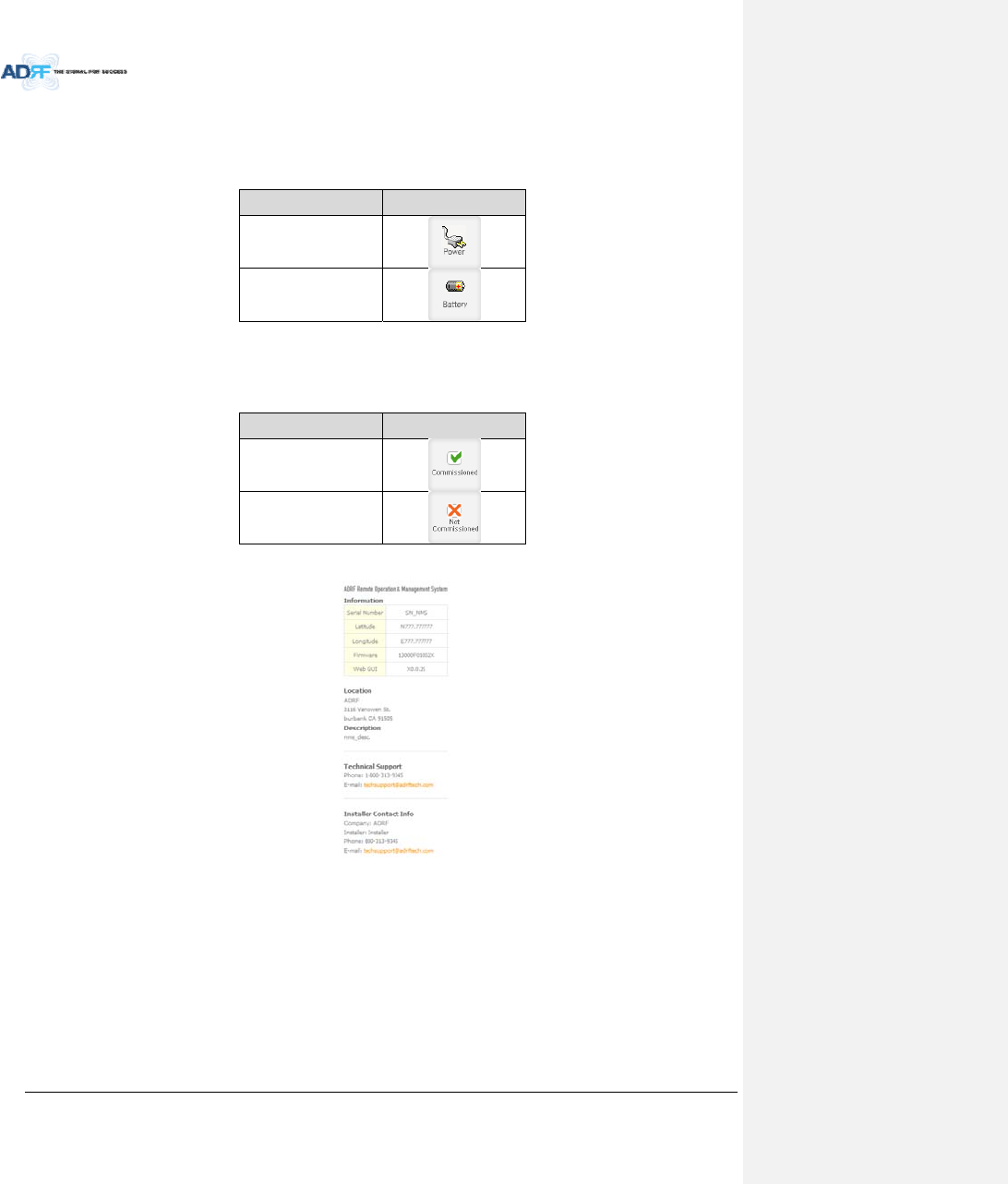
8.2.1.5 Information
Figure8‐4ADXDASGeneralInformation
Information:Displaystheserialnumber,latitude/longitude,firmwareversionofselectedmodule,andWeb
GUIversionoftheNMS.
Location:DisplaystheaddresswheretheADXDASisinstalled.
Description:Displaysthedescriptionofselectedmodule.Thedescriptionofeachmodulecanbeeditedfrom
theInstalltab.Itisrecommendedtousethelocationofthemoduleasthedescription.Thisdescription
informationcanbeseenwhenhoveringoverthedevicetreeinordertoeasilyidentifyeachcomponent.
TechnicalSupport:DisplaysADRF’sTechnicalSupportcontactinformation.
InstallerContactInfo:Displaysthecontactinformationoftheinstaller.
AdvancedRFTechnologies,Inc. 68
8.2.2 StatusTab
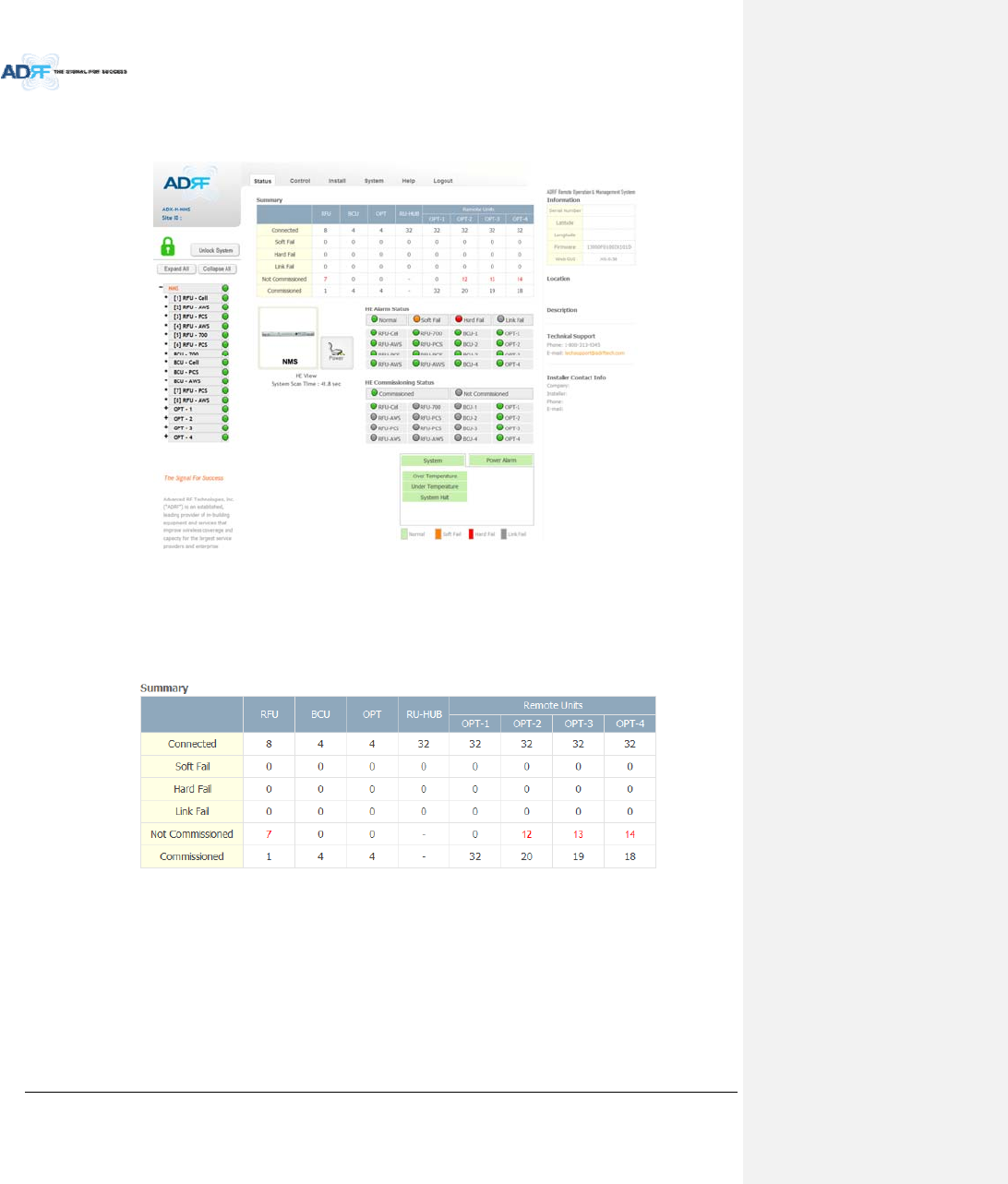
8.2.2.1 Status–NMS
Figure8‐5Status‐NMS
TheNMSStatuspageprovidesanoverallviewofhowthesystemisperforming.FromtheNMSStatuspage,
theusercanseewhatmodulesareconnectedtoADXDAS.Inaddition,theusercanseeifanyalarmsarepresent
inthesystemandalsothecommissioningstatusofeachmodule.
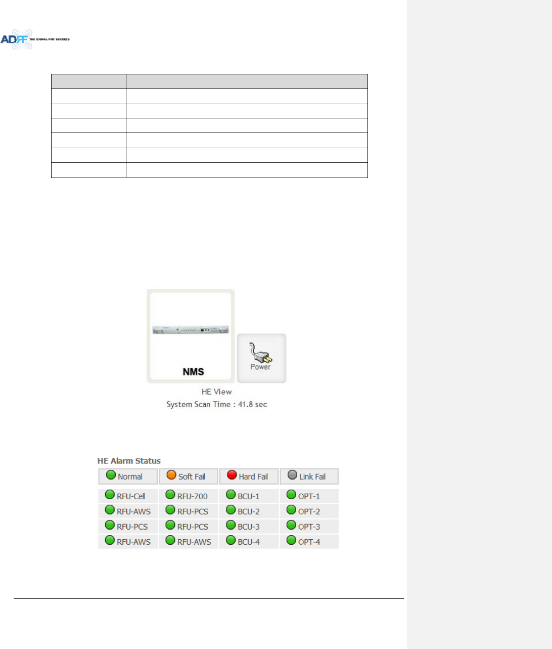
8.2.2.1.1 SystemSummary
Figure8‐6SystemSummary
TheSummarysectionprovidestheuserwiththenumberofcomponentsphysicallyconnected,thenumberof
soft/hard/linkfailspresentinthesystem,andalsothenumberofcommissionedandnon‐commissioned
componnets.
AdvancedRFTechnologies,Inc. 69
Table8‐5SystemSummaryDescription
ParametersDescription
ConnectedDisplaythenumberofmodulesphysicallyconnectedtoADXDAS
SoftFailDisplaythenumberofsoftfailpresentoneachmodule
HardFailDisplaythenumberofhardfailpresentoneachmodule
LinkFailDisplaythenumberoflinkfailpresentoneachmodule
NotCommissionedDisplaythenumberofnon‐commissionedorcommissionfailedmodule
CommissionedDisplaythenumberofsuccessfullycommissionedmodule
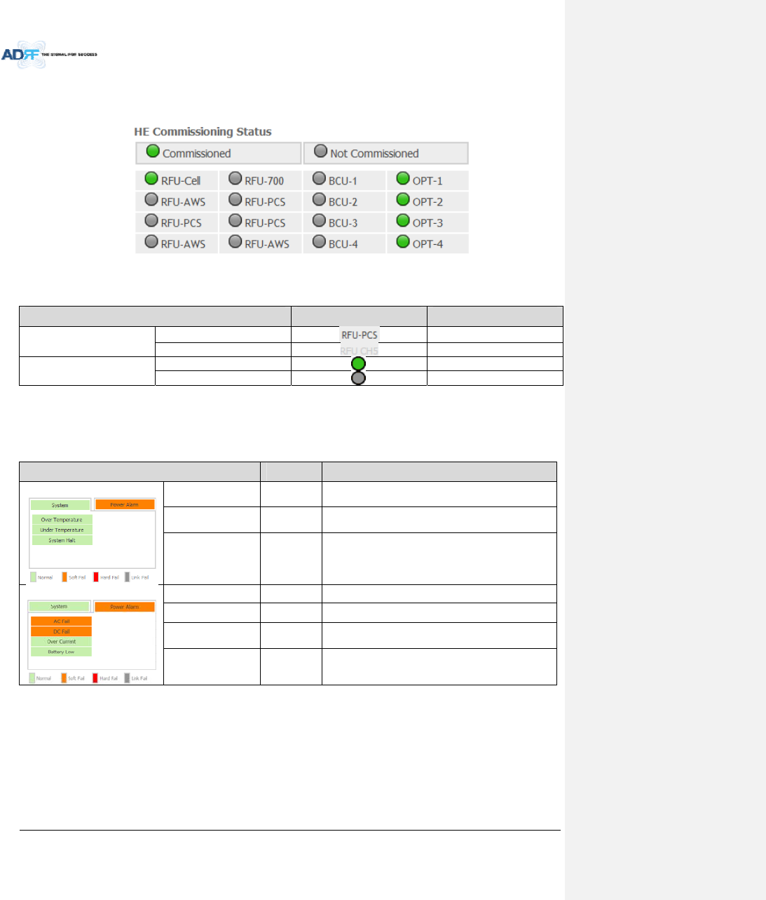
8.2.2.1.2 HEView/RUView,SystemScanTime
HEView/RUView
‐ DisplayswhethertheNMSissettoHEvieworRUview.
‐ Refertosection3.1.1.4
SystemScanTime
‐ Displaysthetimeittakestoscanandupdatetheinformationofallthemodulesthatareonthenavigation
tree.Thistimewillincreaseasmorecomponentsareaddedtothesystem.
‐ WhenNavigationTreeisunlocked,theusershouldwaitatleastthe“SystemScanTime”forthesystemto
detectnewlyaddedhardware.
Figure8‐7Systemscantime,HEview/RUview
8.2.2.1.3 HEAlarmStatus
DisplaythealarmstatusofeachHEcomponent.
Figure8‐8HEalarmstatus
AdvancedRFTechnologies,Inc. 70
8.2.2.1.4 HECommissioningStatus
DisplaycommissioningstatusofeachHEcomponent.
Figure8‐9HECommissioningstatus
Table8‐6DescriptionforHECommissioningstatus
StatusDisplayDescription
InstalledStatusPhysicallyInstalledTextisblack
PhysicallyNot‐InstalledTextisgray
CommissioningStatusSuccessGreen
FailedornotcommissionedGray
8.2.2.1.5 Alarm
DisplaysalarmstatusoftheNMS.Ifanalarmispresentinthesystem,thecolorofthesystemalarmtabwill
changeaccordingtothetypeoffailure.
Table8‐7DescriptionforNMSalarm
AlarmSeverityDescription
System
OverTemperatureHardFail/
SoftFail
TemperatureofNMSishigherthanthethreshold
levelforovertemperaturealarm
UnderTemperatureSoftFailTemperatureoftheNMSislowerthanthethreshold
levelforundertemperaturealarm
SystemHaltHardFailHEsystemhalt
PowerAlarm
ACFailSoftFailACpowerisoperatingoutsideofitsnormalrange
DCFailSoftFailDCpowerisoperatingoutsideofitsnormalrange
OverCurrentHardFailTotalcurrentofHEishigherthanthethresholdlevel
forovercurrentalarm
BatteryLowSoftFailVoltageofbatteryconnectedtoHEPSUislowerthan
thedefinedthreshold
AdvancedRFTechnologies,Inc. 71
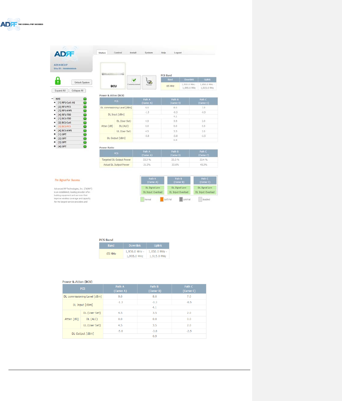
8.2.2.2 Status–BCU
Figure8‐10Status–BCU
8.2.2.2.1 Band
DisplaysthebandwidthandthefrequencyrangesforDLandULoftheBCUmodule.
Figure8‐11Status–BCUBand
8.2.2.2.2 Power&Atten
Figure8‐12Status–BCUPower&Atten
AdvancedRFTechnologies,Inc. 72
DLCommissioningLevel:DisplaysthecommissioninglevelforeachindividualRFpath.Ifunithasnot
beencommissioned,“NotCommissioned”willbedisplayed.
DLInput:DisplaysthecurrentlyincomingsignalstrengthofeachRFpathalongwiththecompositeDL
inputpowerofall3RFpaths.
Atten:Displaystheattenuationvaluesthatthesystemiscurrentlyusingwhichisdefinedbythe
powerratiosspecifiedbytheuser.
DLOutput:DisplaystheoutputvalueforeachRFpathalongwiththecompositeDLoutputpowerof
all3RFpaths.TheDLOutputlevelforeachRFpathwillnotexceed5dBmandthecompositeoutput
powerwillnotexceed10dBm.
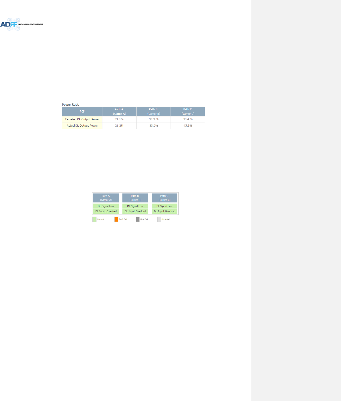
8.2.2.2.3 PowerRatio
Figure8‐13Status–BCUPowerRatio
TargetedDLOutputPower:Displaysdesiredpowerratiosspecifiedbytheuser.Ifunithasnotbeen
commissioned,“NotCommissioned”willbedisplayed.
ActualDLOutputPower:Displaysthecurrentlypowerratiosthatthesystemisusing.Thesevalues
willfluctuatebasedontheamountoftrafficthatisinthesystem.
8.2.2.2.4 Alarm
DisplaysthecurrentalarmstatusofeachindividualRFpath.ParametersforbothDLSignalLowandDLInput
OverloadcanbespecifiedfromtheControltab.
Figure8‐14Status–BCUAlarm
AdvancedRFTechnologies,Inc. 73
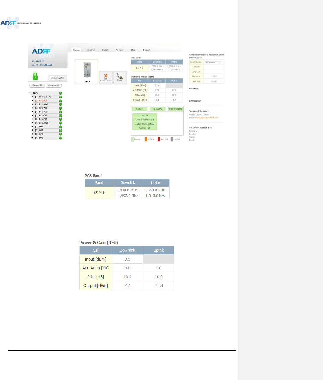
8.2.2.3 Status–RFU
Figure8‐15Status–RFU
8.2.2.3.1 Band
DisplaysthebandwidthandthefrequencyrangesforDLandULoftheRFUmodule.
Figure8‐16Status–RFUBand
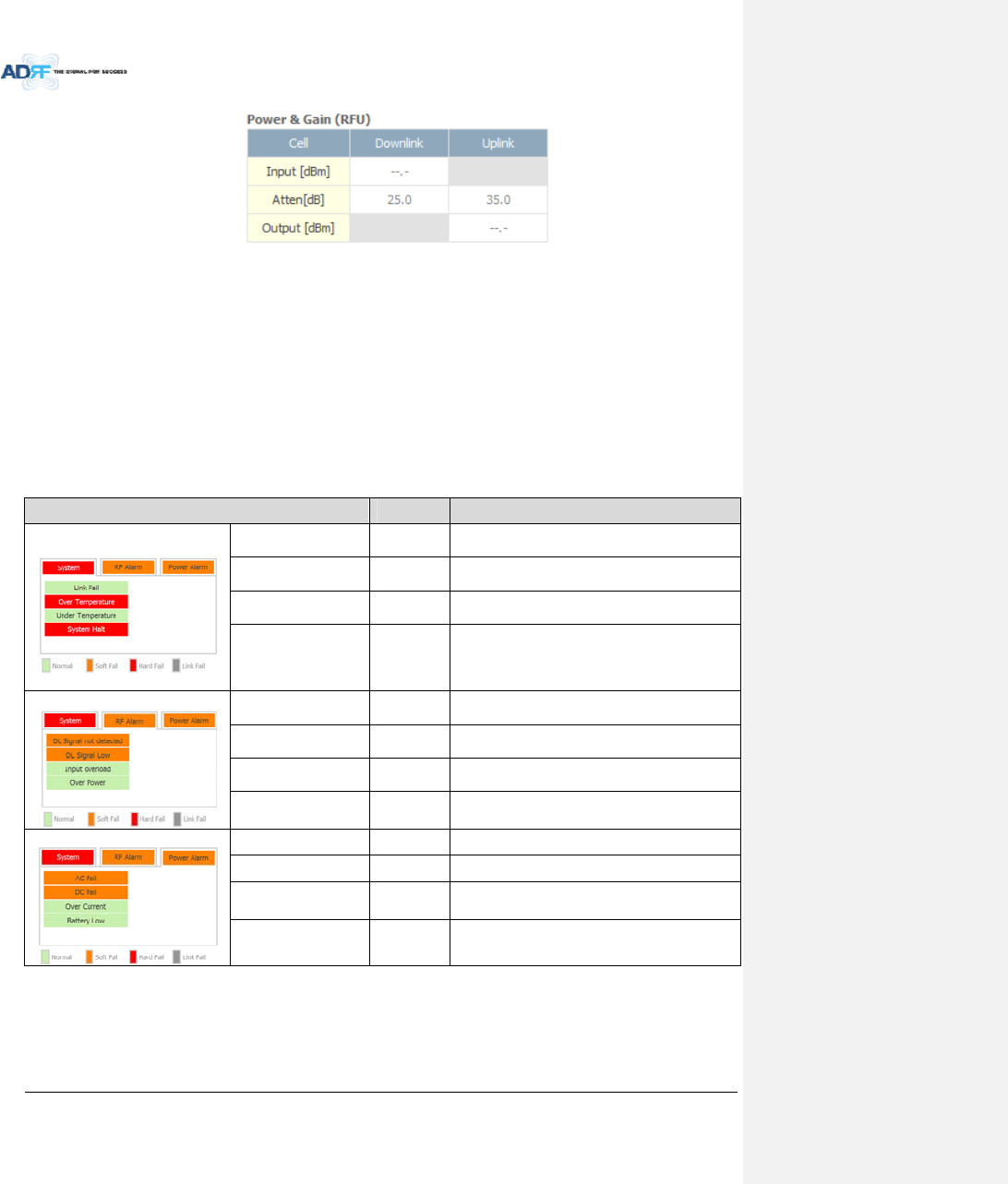
8.2.2.3.2 Power&Gain(Admin/User)
AdminMode‐ DisplaystheDownlinkInput/output,Downlink/UplinkAttenuation,andUplink
Output.
UserMode‐DisplaystheDownlinkInput,Downlink/UplinkAttenuation,andUplinkOutput.
Figure8‐17Power&GainDisplay(Admin)
AdvancedRFTechnologies,Inc. 74
Figure8‐18Power&GainDisplay(User)
Input[dBm]:DisplaystheDownlinkRFinputlevelwhichcomesfromtheADX‐H‐BCU,BTS.Thisvalueshould
bebetween0to25dBm.
ALCAtten[dB]:TheamountofattenuationthatisbeingusedbythesystemwhenALCisactive.
Atten[dB]:Theamountofattenuationthathasbeensetmanuallybytheuser.
Output[dBm]:Thedownlink/uplinkoutputpoweroftheRFUandNOTtheoutputpoweroftheRU.
8.2.2.3.3 Alarm
DisplaysSystem,RF,andPowerAlarms.Ifanalarmispresentinthesystem,thenthecolorofthetabwill
changeaccordingtothetypeoffailure.
Table8‐8RFUAlarmStatus
AlarmSeverityDescription
System
LinkFailSoftFailAcomponentisphysicallyconnected,butthe
NMSisunabletocommunicatewithit.
OverTemperatureHardFail/
SoftFail
ThetemperatureofNMSishigherthanthe
thresholdlevelforovertemperaturealarm.
UnderTemperatureSoftFailThetemperatureofNMSislowerthanthe
thresholdlevelforundertemperaturealarm.
SystemHaltHardFail
Systemwillgointoa“SystemHalt”statewhena
hardfailalarmdoesnotclearafter10checks.
SystemHaltcanonlybeclearedwithapower
cycle,reboot,orfactorysettings.
RFAlarm
DLSignalnotdetectedSoftFailDownlink inputsignal islowerthanthedefined
thresholdbyuser.
DLSignalLowSoftFailDownlinkinputsignal islowerthanthedefined
thresholdbyuser.
InputOverloadHardFail/
SoftFail
Downlinkinputsignal ishigherthanthedefined
threshold.
OverpowerHardFail/
SoftFail
Uplinkoutputsignalishigherthanthedefined
thresholdbyuser.
PowerAlarm
ACFailSoftFailACpowerisnotoperatingwithinparameters.
DCFailSoftFailDCpowerisnotoperatingwithinparameters.
OverCurrentHardFailTotalcurrentofHEishigherthanthethreshold
levelforovercurrentalarm.
BatteryLowSoftFailVoltageofbatteryconnectedtoHEPSUislower
thanthedefinedthreshold.
AdvancedRFTechnologies,Inc. 75
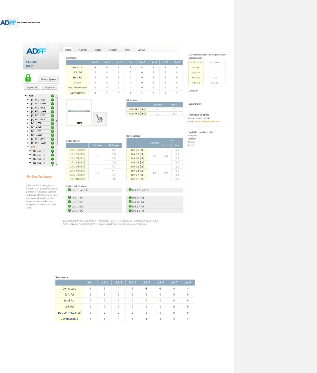
8.2.2.4 Status–ODU
Figure8‐19Status‐OPT
8.2.2.4.1 Summary
TheSummarysectiondisplaysthenumberofremotemodulesthatarephysicallyconnected,thenumberof
soft/hard/linkfailalarms,andthenumberofRemoteModulethathavebeencommissionedandthenumberof
RemoteModulethatneedtobecommissioned.
Figure8‐20Summary(Status–OPT)
AdvancedRFTechnologies,Inc. 76
Table8‐9SummaryDescription
ParametersDescription
ConnectedDisplaysthenumberofRemoteModule’sconnectedtotheADX‐H‐OPT.
SoftFailDisplaysthetotalnumberofsoftfailpresent.
HardFailDisplaysthenumberofhardfailpresentoneachmodule.
LinkFailDisplaysthenumberoflinkfailpresentoneachmodule.
NotCommissionedDisplaysthenumberofnon‐commissionedorcommissionfailedmodule.
CommissionedDisplaythenumberofsuccessfullycommissionedmodule
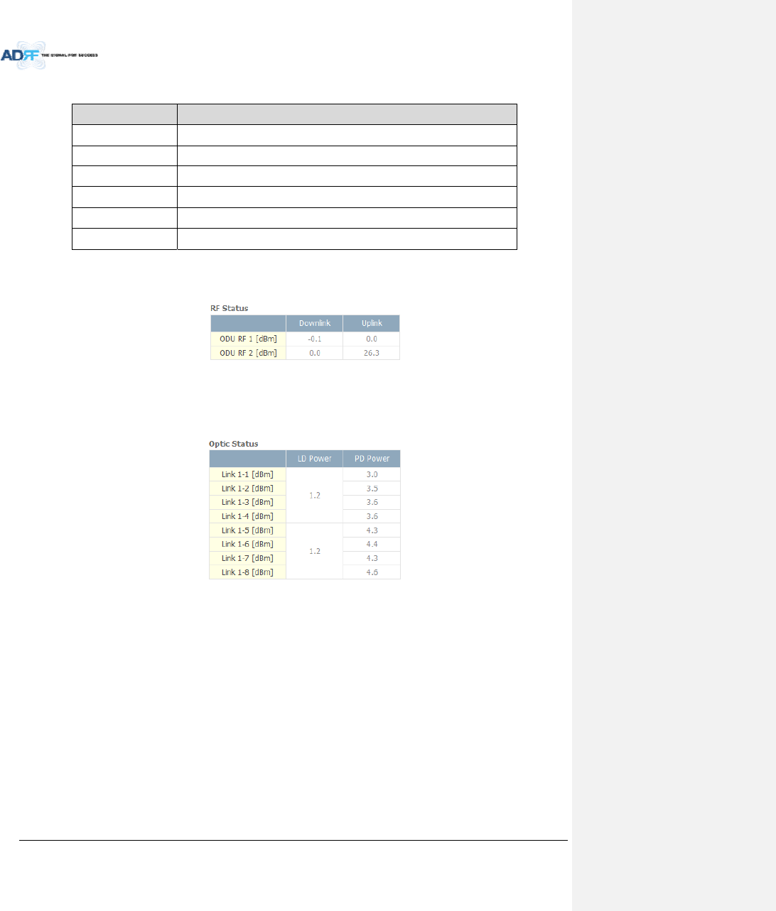
8.2.2.4.2 RFStatus
DisplaystheDLinputpowerandtheULoutputpowerforeachODU.
AnODURackiscomposedof2ODUs.
Figure8‐21RFStatus(Status–OPT)
8.2.2.4.3 OpticStatus
DisplayLDPowerandPDPowerforeachopticpath.LDPoweristhepowerthatisbeingsenttotheRUand
PDPoweristhepowerthatisbeingreceivedfromtheRU.
Figure8‐22OpticStatus(Status–ODU)
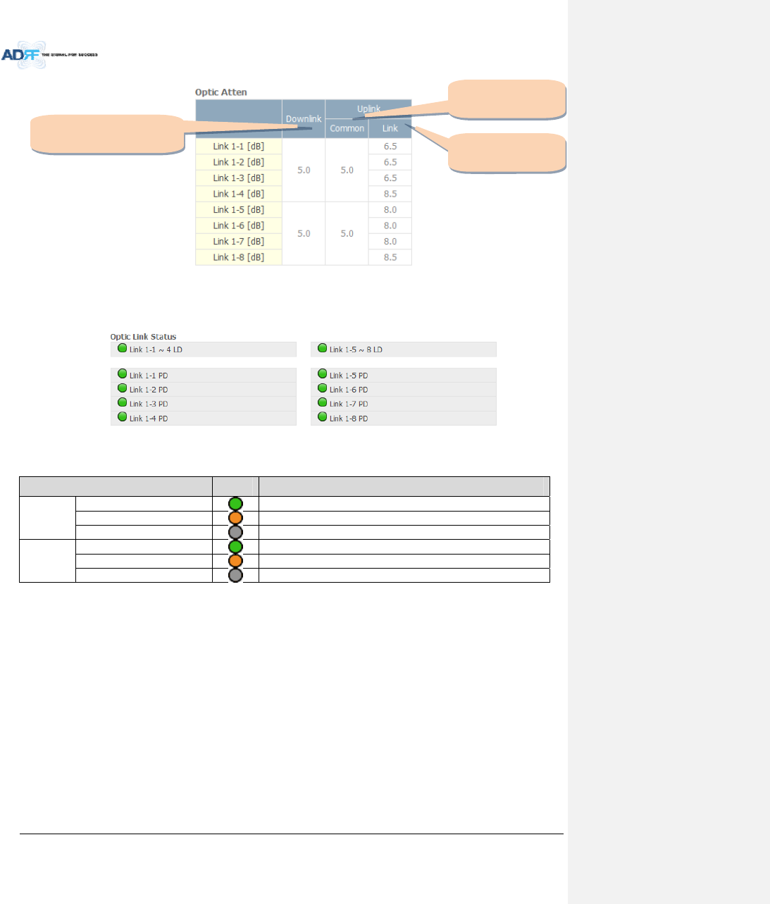
8.2.2.4.4 OpticAtten(AdminOnly)
TheADX‐H‐ODUhas3typesofattenuators.
DownlinkCommonAttenuator‐DisplaysthecommonattenuationlevelontheDLpath.
UplinkCommonAttenuator‐DisplaysthecommonattenuationlevelontheULpath.
UplinkOpticAttenuator‐Displaystheamountofattenuationusedateachopticallink.
AdvancedRFTechnologies,Inc. 77
Figure8‐23OpticAttenuation(Status–OPT)
8.2.2.4.5 OpticPathStatus
Displaystheopticstatusforeachopticpath
Figure8‐24OpticPathStatus(Status–OPT)
Table8‐10Descriptionforopticpathstatus
StatusDisplayDescription
LDStatus
NormalGreen,opticsignalbeingsenttoMasterRUis>‐5dBm
LDfailOrange,opticsignalbeingsenttoMasterRUis<‐5dBm
NotConnectedGray,noconnectionbetweenODUandMasterRU
PDStatus
NormalGreen,opticsignalbeingreceivedfromMasterRUis>‐10dBm
PDfailOrange,opticsignalbeingreceivedfromMasterRUis<‐10dBm
CommFailorNotConnectedGray,noconnectionbetweenODU andMasterRU
Downlink
Commonattenuator
Uplink
Commonattenuator
Uplink
Opticattenuator
AdvancedRFTechnologies,Inc. 78
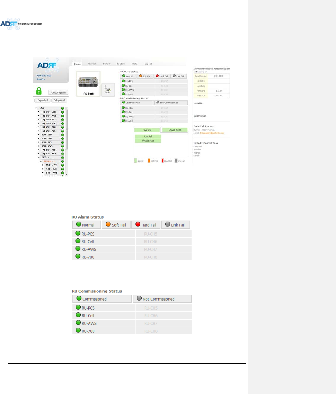
8.2.2.5 Status–RUHub
RU‐HubisnotseparatemodulebutisintegratedintothemasterRU.ThepictureofRUHubdisplayedonweb
basedGUIissameasthepictureofmasterRU.
Figure8‐25Status‐RUHub
8.2.2.5.1 RUAlarmStatus
TheRUHubcansupportupto8remotemodules.TheRUalarmstatusdisplaysthealarmstatusofeach
remotemodule.
Figure8‐26RUAlarmStatus(Status‐RUHub)
8.2.2.5.2 RUCommissioningStatus
DisplaytheCommissioningstatusofeachRemoteModule.
Figure8‐27RUCommissioningStatus(Status‐RUHub)
AdvancedRFTechnologies,Inc. 79
Table8‐11DescriptionforRUCommissioningstatus
StatusDisplayDescription
InstalledStatusInstalledTextisblack
Not‐InstalledTextisgray
CommissioningStatusSuccessGreen
FailornotyetGray
8.2.2.5.3 Alarm
Table8‐12AlarmStatus(Status‐RUHub)
AlarmSeverity Description
SystemLinkFailSoftFail Presentwhenamodulecannotcommunicatewiththe
NMS
SystemHaltHardFail
Systemwillgointoa“SystemHalt”statewhenahard
failalarmdoesnotclearafter10checks.SystemHalt
canonlybeclearedwithapowercycle,reboot,or
factorysettings.
PowerAlarmACFailSoftFail ACpowerisnotwithinparameters.
DCFailSoftFail DCpowerisnotwithinparameters.
OverCurrentHardFail TotalcurrentofRUishigherthanthethresholdlevelfor
overcurrentalarm
BatteryLowSoftFail VoltageofbatteryconnectedtoRUPSUislowerthan
thedefinedthreshold
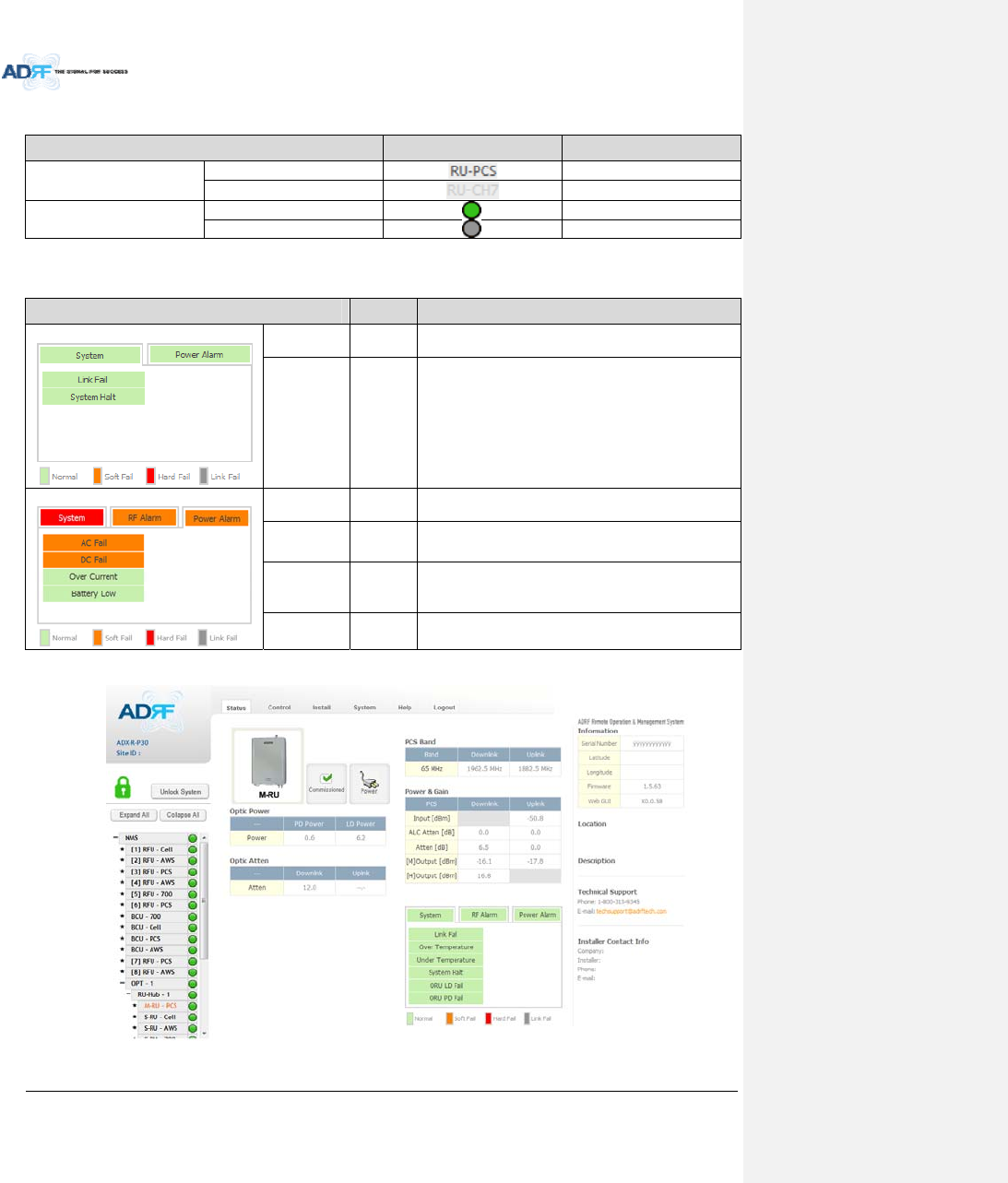
8.2.2.6 Status–Remotemodule
Figure8‐28Status–RemoteModule

AdvancedRFTechnologies,Inc. 80
8.2.2.6.1 Band
Displaythespectrumthatisbeingused.Thebandcolumndisplaysthebandwidththathasbeenused.The
downlinkcolumndisplaysthecenterfrequencyoftheuseddownlinkband.Theuplinkcolumndisplaysthecenter
frequencyoftheuseduplinkband.
Figure8‐29PCSBandInformation(Status–RemoteModule)
8.2.2.6.2 Power&Gain(Admin/User)
DisplaytheDownlinkoutput,Downlink/UplinkAttenuation,andUplinkInput/output.
Figure8‐30Power&Gain(Admin)
Figure8‐31Power&Gain(User)
Admin
o Input[dBm]:DisplaystheRFinputlevelforUplinkonlyfortheRemoteModule.
o ALCAtten[dB]:TheamountofattenuationusedwhenALCisactivate.
o Atten[dB]:Theamountofattenuationmanuallysetbytheuser.
o [M]Output[dBm]:OutputpowerofRFtransceiver(1ststageamplification).
o [H]Output[dBm]:OutputpowerofdownlinkHPA(2ndstageamplification).
User
o Input[dBm]:DisplaystheRFinputlevelforUplinkonlyfortheRemoteModule.
o Atten[dB]:Theamountofattenuationmanuallysetbytheuser.
o Output[dBm]:Displaysthetotalcompositeoutputpower.
AdvancedRFTechnologies,Inc. 81
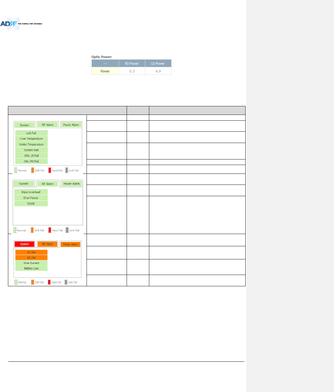
8.2.2.6.3 OpticPower(Master‐RUOnly)
DisplaytheLDPowerandPDPowerofopticmoduleinsidetheMasterRU.
Figure8‐32OpticPower(Status–MasterRUonly)
8.2.2.6.4 OperatingStatus
Table8‐13OperatingStatus(Status–RemoteModule)
AlarmSeverity Description
SystemLinkFailSoftFail NocommunicationwithNMS.
OverTemperatureHardFail
/SoftFail
Temperature ishigherthanthethresholdlevelfor
overtemperaturealarm.
Under
TemperatureSoftFail Temperatureislowerthanthethresholdlevelfor
undertemperaturealarm.
SystemHaltHardFail
SystemhaltoneithertheMasterRUorSlaveRU.
Systemhaltoccurswhenahardfailalarmfailsto
clearafter10checks.
ORULDFailSoftFail LDFailpresentintheMasterRU’sopticunit.
ORUPDFailSoftFail PDFailpresentintheMasterRU’sopticunit.
RFAlarmInputOverloadHardFail Uplinkinputsignalishigherthanthedefined
threshold.
OverPowerHardFail
/SoftFail
Downlinkoutputsignalishigherthanthedefined
thresholdbyuser.
VSWRSoftFail Triggeredwhenpowerisbeingreflectedbackto
thesystem,typicallyduetoalooseconnector.
PowerAlarmACFailSoftFail ACpowerisnotoperatingwithinparameters.
DCFailSoftFail DCpowerisnotoperatingwithinparameters.
OverCurrentHardFail TotalcurrentofRUishigherthanthethreshold
levelforovercurrentalarm.
BatteryLowSoftFail VoltageofbatteryconnectedtoHEPSUislower
thanthedefinedthreshold.
AdvancedRFTechnologies,Inc. 82
8.2.3 ControlTab
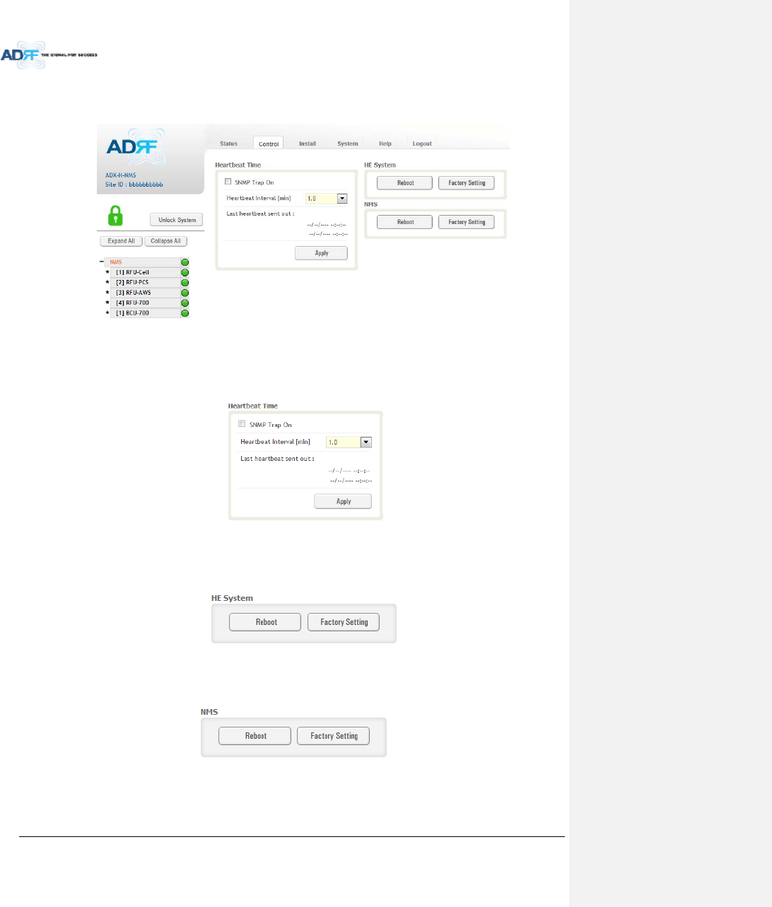
8.2.3.1 Control–NMS
Figure8‐33Control‐NMS
8.2.3.1.1 HeartbeatTime
AllowstheusertoenableordisableSNMPtrapsfrombeingsentoutandalsospecifytheHeartbeatinterval.
Timeanddatestampsofthelast2heartbeatswillbedisplayedinthe“Lastheartbeatsentout”section.
Figure8‐34Heartbeat(Control–NMS)
8.2.3.1.2 HESystem
AllowstheusertoperformaHEsystemrebootorHEfullsystemfactorysettings
Figure8‐35HESystemReboot&FactorySetting(Control–NMS)
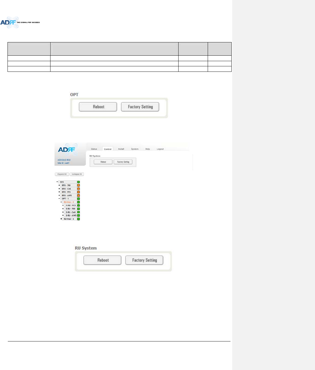
8.2.3.1.3 NMSSystem
AllowstheusertoperformaNMSUnitrebootorNMSfactorysettings
Figure8‐36NMSSystemReboot&FactorySetting(Control–NMS)
AdvancedRFTechnologies,Inc. 83
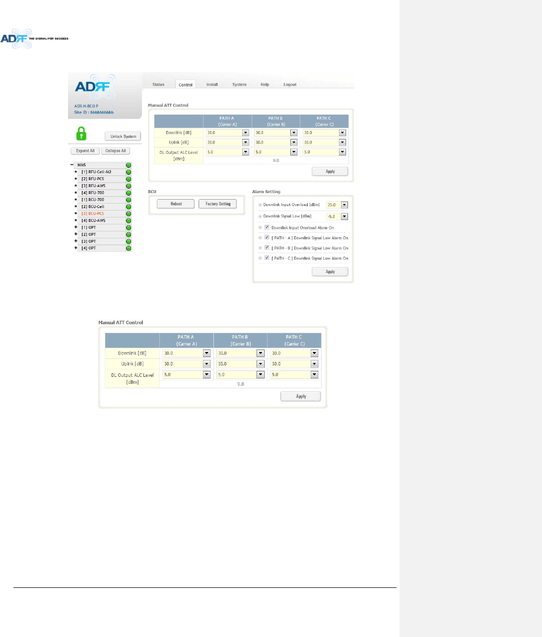
8.2.3.2 Control–BCU
Figure8‐37Control–BCU
8.2.3.2.1 ManualATTControl
Figure8‐38Control–BCUManualATTControl
Downlink:AllowstheusertomanuallyadjusttheDLattenuationlevelsforeachRFpath.Adjusting
thesesettingsisnotrecommendedsinceitwillchangethepowerratiossetbytheuser.
Uplink:AllowstheusertomanuallyadjusttheULattenuationlevelsforeachRFpath.Adjustingthese
settingsisnotrecommended,unlessadditionalattenuationisneededontheULpath.
DLOutputALCLevel:AllowstheusertomanuallysettheDLOutputALCLevelsforeachRFpath.
Adjustingthesesettingsisnotrecommendedsinceitwillchangethepowerratiossetbytheuser.
ThesesettingsareautomaticallysetbythesystemduringtheBCUcommissioningprocess.This
sectionalsodisplaysthecompositeDLOutputALCLevelwhichisthevaluethatcanbeusedto
commissiontheRFU.
AdvancedRFTechnologies,Inc. 84
8.2.3.2.2 Reboot/FactorySetting
AllowstheuserrebootorrestorefactorysettingsoftheBCU.
Figure8‐39Control–BCUReboot/FactorySetting
8.2.3.2.3 AlarmSetting
Figure8‐40Control–BCUAlarmSetting
DownlinkInputOverload:AllowstheusertospecifythelevelatwhichtheDLInputOverloadalarmis
triggered.Valuesrangefrom0dBmto+25dBm.
DownlinkSignalLow:AllowstheusertospecifythelevelatwhichtheDLSignalLowalarmistriggered.
Valuesrangefrom‐10dBmto+20dBm.
DownlinkInputOverloadAlarmOn:AllowstousertoenableordisabletheInputOverloadAlarm
[Path–A/B/C]DownlinkSignalLowAlarmOn:AllowstheusertoenableordisabletheDLSignalLow
alarmforeachRFpath.
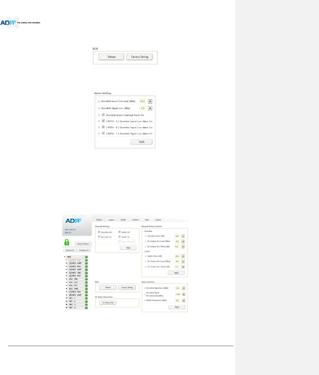
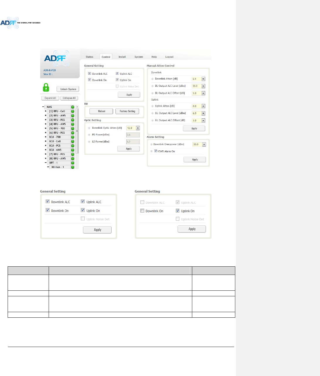
8.2.3.3 Control–RFU
Figure8‐41Control‐RFU
AdvancedRFTechnologies,Inc. 85
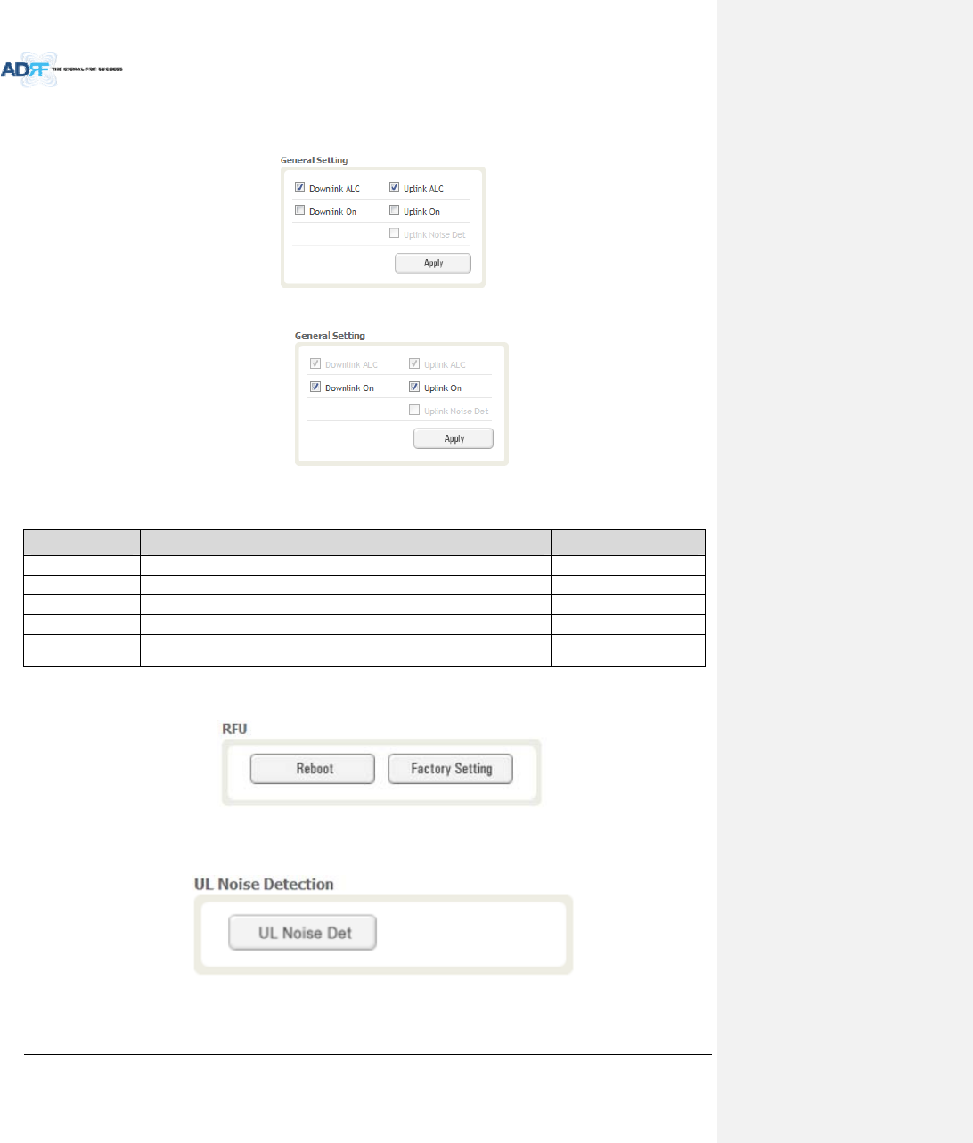
8.2.3.3.1 GeneralSetting
Toenableanyofthesettings,clickonthecheckboxandclicktheApplybutton.
Figure8‐42GeneralSetting(Control–RFU)(Admin)
Figure8‐43GeneralSetting(Control–RFU)(User)
Table8‐14DescriptionforGeneralSetting
NameDescriptionAvailableAccounts
DownlinkALCEnablesordisablesDownlinkALCAdministrator
UplinkALCEnablesordisablesUplinkALCAdministrator
DownlinkONEnablesordisablestheRFUDownlinkpath Administrator,User
UplinkONEnablesordisables theRFUUplinkpathAdministrator,User
UplinkNoiseDetDisplaysifthemoduleisturnedonoroffduetotheULNoiseDetection
Routine
Administrator
8.2.3.3.2 Reboot/FactorySetting
AllowstheuserrebootorrestorefactorysettingsoftheRFU.
Figure8‐44Reboot&FactorySetting(Control–RFU)
8.2.3.3.3 UplinkNoiseDetection(AdminOnly)
Figure8‐45ULNoiseDetection(Control–RFU)
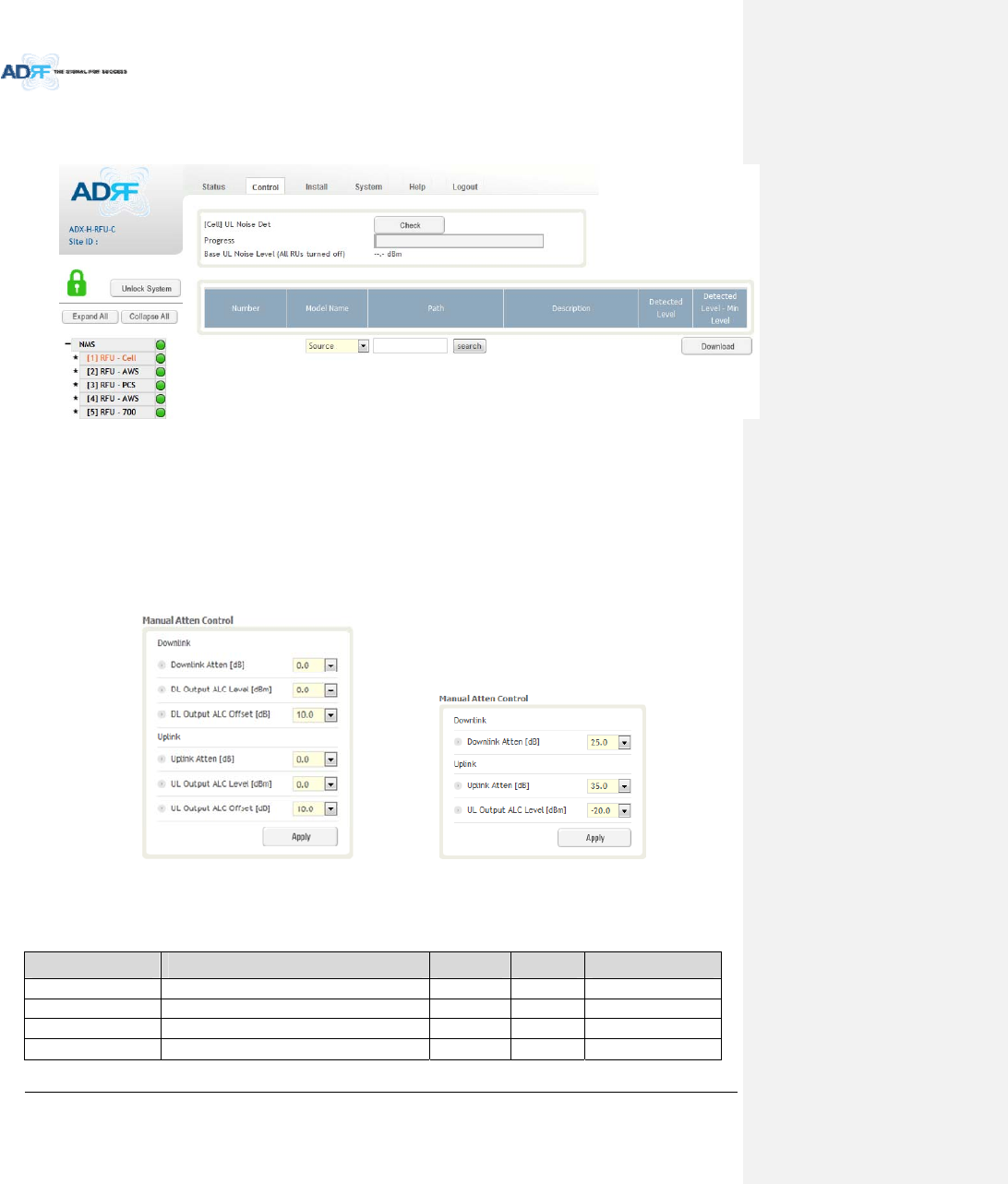
AdvancedRFTechnologies,Inc. 86
The“ULNoiseDet”buttonwilltakeyoutotheULNoiseDetectionpagewhichwillallowyoutoruntheULNoise
Detectionroutine.
Figure8‐46ULNoiseDetection‐PCSband
TheAutoULnoisemeasurementroutinecanberunbyclickingontheCheckbutton.AfterallULnoise
measurementhavebeentaken,thelevelsforeachULpathwillbedisplayedandalongwiththedifference
betweenminimumdetectlevelandmeasureddetectlevel.
TheuserwillbeabletoseewhichpathisgeneratingtheelevatedULnoiselevelbasedonthemeasureddetect
levelanddifferencevalue.
TonavigatebacktotheRFUcontrolpage,clickontheControltabagain.
8.2.3.3.4 ManualAttenControl
(Admin)(User)
Figure8‐47ManualAttenuatorControlSetting(Control–RFU)
Table8‐15DescriptionforMainGainControlSetting(Control–RFU)
NameDescriptionRangeStepAvailableAccounts
DownlinkAttenDownlinkAttenuatortobeadjustedmanually 0~25dB 0.5dB Administrator,User
UplinkAttenUplinkAttenuatortobeadjustedmanually 0~35dB 0.5dB Administrator,User
DLOutputALCLevelTosettheMaxoutputALClevel‐10~0dBm 0.5dBm Administrator
ULOutputALCLevelTosettheMaxoutputALClevel‐20~0dBm 0.5dBm Administrator,User
AdvancedRFTechnologies,Inc. 87
DLOutputALCOffsetTosettheMaxoutputALCOffset‐10~0dBm 0.5dBm Administrator
ULOutputALCOffsetTosettheMaxoutputALCOffset‐20~0dBm 0.5dBm Administrator
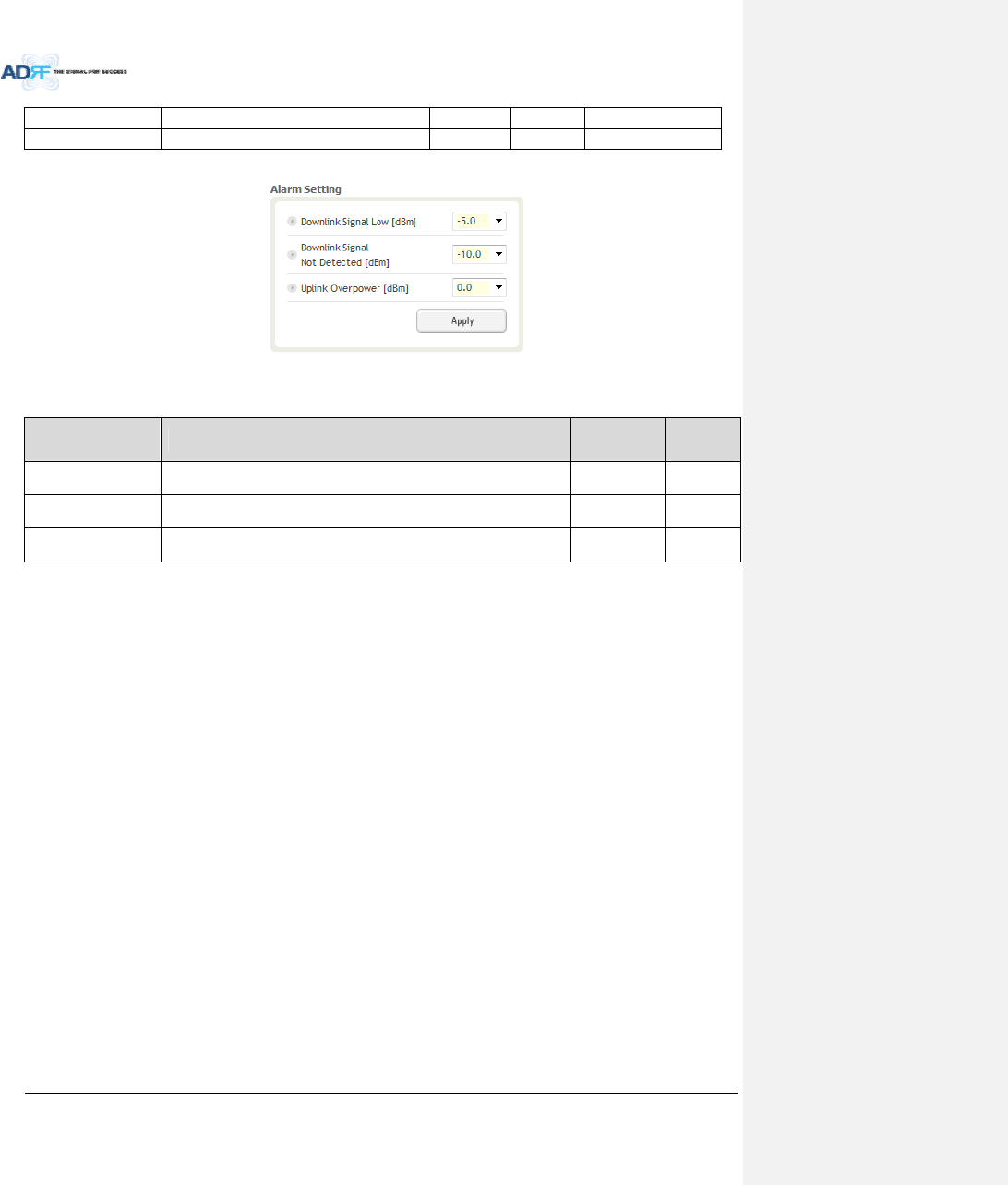
8.2.3.3.5 AlarmSetting
Figure8‐48AlarmThresholdSetting(Control–RFU)
Table8‐16DescriptionforAlarmThresholdSetting(Control–RFU)
NameDescriptionRangeDefault
threshold
DownlinkSignalLowAllowstheusertospecifytheminimumincomingDLinputsignallevel
beforetriggeringa“DownlinkSignalLow”soft‐failalarm.‐10~20dBm‐5dBm
DownlinkSignalNot
Detected
AllowstheusertospecifytheminimumincomingDLinputsignallevel
beforetriggeringa“DownlinkSignalNotDetected”soft‐failalarm.‐10~20dBm‐10dBm
UplinkOverPowerAllowstheusertospecifythehowstrong theoutput signalofuplinkcan
bebeforetriggeringan“UplinkOverPower”HardFailalarm.‐20~0dBm0dBm
AdvancedRFTechnologies,Inc. 88
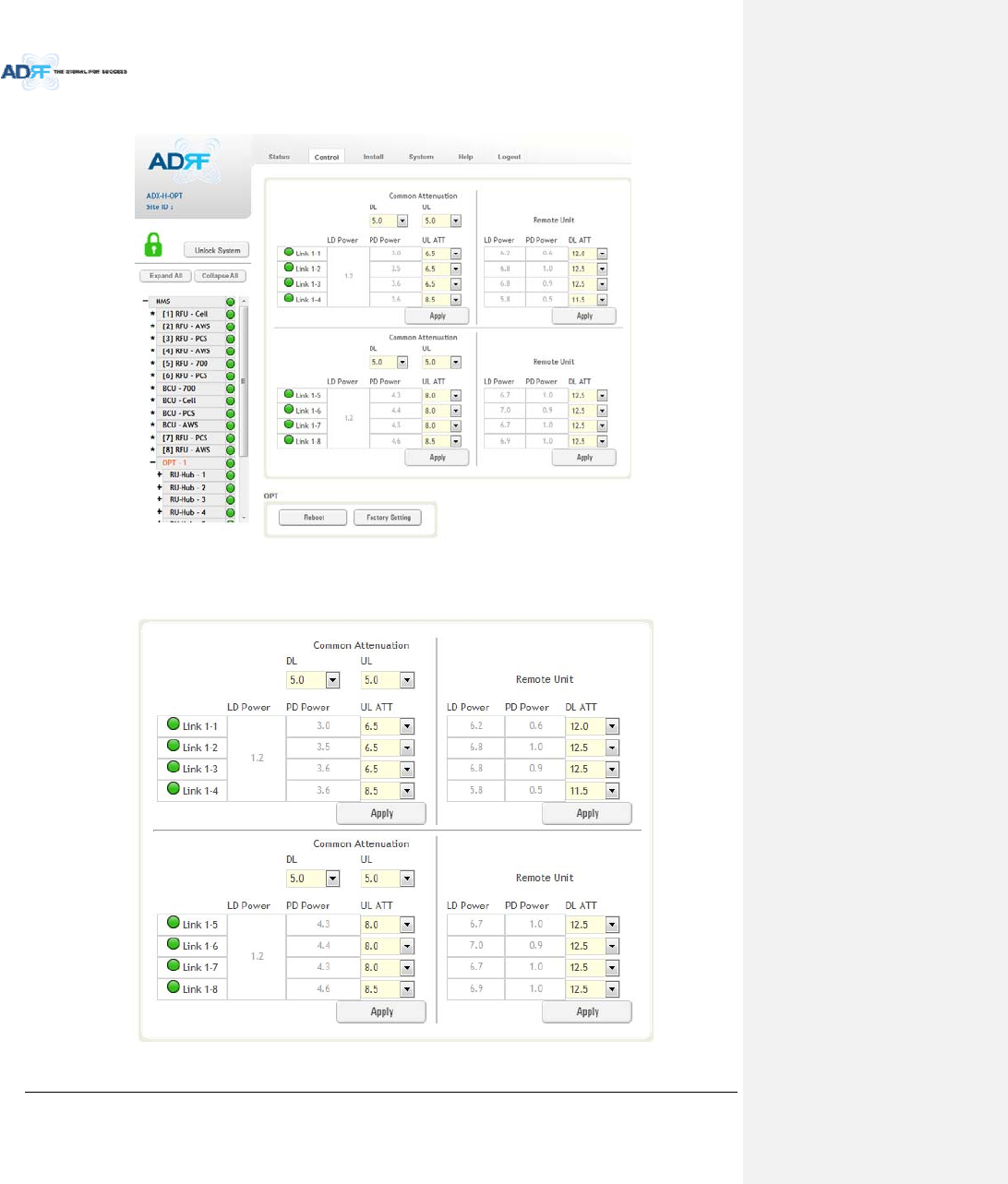
8.2.3.4 Control–ODU
Figure8‐49Control–OPT
8.2.3.4.1 OpticAttenuation(AdminOnly)
Figure8‐50OpticAttenuation–OPT
AdvancedRFTechnologies,Inc. 89
Table8‐17DescriptionforOpticAttenuation(Control–OPT)
NameDescriptionRangeDefault
threshold
DL/ULcommonATTAllowstheusertocontroloverallopticDL/ULpathgain. 0~30dB 5dB
DLATTUsedtocompensateDLopticloss.0~13dB 13dB
ULATTUsedtocompensateULopticloss.0~13dB 13dB
8.2.3.4.2 Reboot/FactorySetting
AllowstheusertoperformODUrebootorODUfactorysettings.
Figure8‐51Reboot&factorySetting(Control–OPT)
8.2.3.5 Control–RHHub
Figure8‐52Control–RUHub
8.2.3.5.1 Reboot/FactorySetting
AllowstheusertoperformRUHubrebootorRUHubfactorysettings
Figure8‐53Reboot&FactorySetting(Control–RUHub)
AdvancedRFTechnologies,Inc. 90
8.2.3.6 Control–RemoteModule(MasterorSlaveRU)
Figure8‐54Control–RemoteModule
8.2.3.6.1 GeneralSetting(Admin/User)
(Admin)(User)
Figure8‐55GeneralSetting(Control‐RU)
Table8‐18DescriptionforGeneralSetting(Control‐RU)
NameDescriptionAvailableAccounts
DownlinkALC
ThissettingallowsyoutoenableordisablethedownlinkALCfunction.When
ALCisenabled,thedownlinkoutputpowerwillnotexceedtheDownlink
OutputLevelspecifiedintheManualAttenControlsection.
Administrator
DownlinkOnThissettingallowsyoutoenableordisabletheDownlinkpath. Administrator,User
UplinkALC
Thissettingallowsyoutoenableordisabletheuplink ALCfunction.WhenALC
isenabled,theUplinkoutputpowerwillnotexceedtheUplinkOutputLevel
specifiedintheManualAttenControlsection.
Administrator
UplinkOnThissettingallowsyoutoenableordisabletheUplinkpath. Administrator,User
AdvancedRFTechnologies,Inc. 91
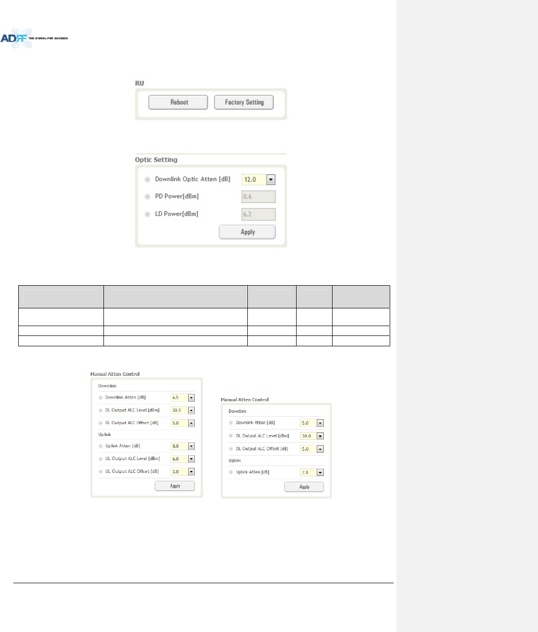
8.2.3.6.2 Reboot/FactorySetting
AllowstheusertoRebootorrestoreFactorySettingsontheremotemodule.
Figure8‐56Reboot&factorySetting(Control‐RU)
8.2.3.6.3 OpticSetting(OnlyMasterRU)(AdminOnly)
Figure8‐57OpticSetting(Control‐RU)
Table8‐19DescriptionforOpticSetting(Control‐RU)
NameDescriptionRangeStepAvailable
Accounts
DownlinkOpticAttenRFattenuatortocompensatetheopticlossof
downlink0~13.0dB0.5dBAdministrator
PDPowerIncomingpowerlevelfromtheODU Administrator
LDPowerOutgoingpowerleveltotheODUAdministrator
8.2.3.6.4 ManualAttenuatorControl
(Admin) (User)
Figure8‐58ManualAttenControl(Control‐RU)
AdvancedRFTechnologies,Inc. 92
Table8‐20DescriptionforManualAttenControl(Control‐RU)
NameDescriptionRangeDefault
threshold
AvailableAccounts
DownlinkAttenAllowstheusertospecifyhowmuchattenuationtouse.0~30dB30dBAdministrator,User
UplinkAttenAllowstheusertospecifyhowmuchattenuationtouse.0~25dB25dBAdministrator,User
DLOutputALC
Level
Theremotemodulewillpreventthedownlinkoutput
powerfromexceedingthespecifiedvalue.5~30dB30dBmAdministrator,User
ULOutputALC
Level
Thesystemwillpreventtheoutputpowertoexceedthe
specifiedvalue.0~10dBm 5or
6dBmAdministrator
DLOutputALC
Offset
Whentheincomingsignallevelincreases,thesystemwill
notadjustthegainlevelsuntilitreachestheALCOffset
Level.
0~10dB5dBAdministrator,User
ULOutputALC
Offset
Whentheincomingsignallevelincreases,thesystemwill
notadjustthegainlevelsuntilitreachestheALCOffset
Level.
0~10dB3dBAdministrator
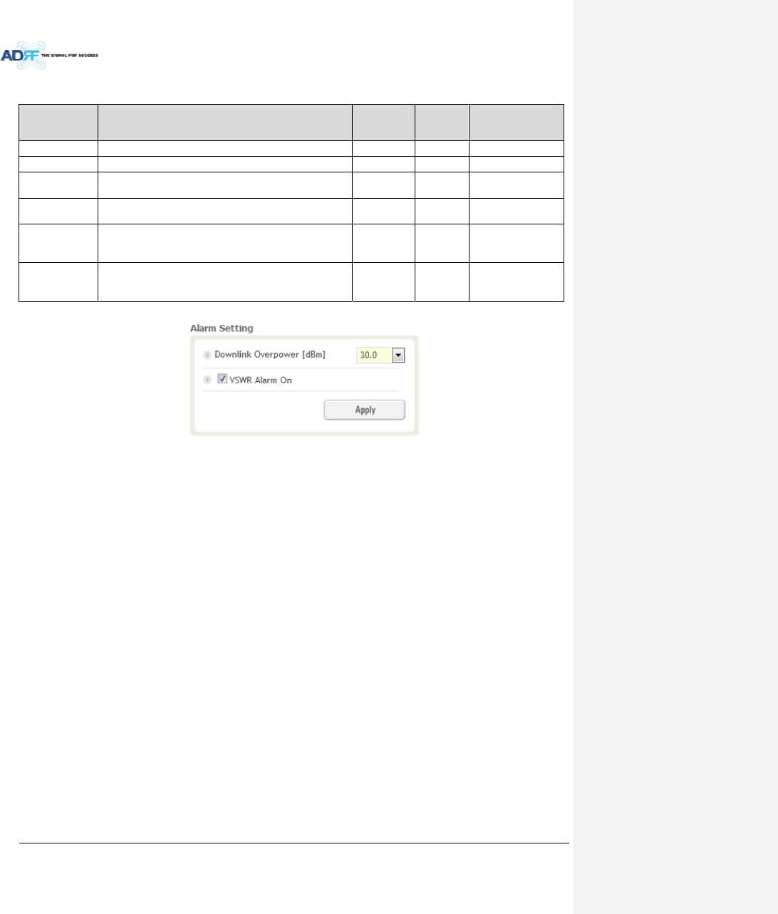
8.2.3.6.5 AlarmSetting
Figure8‐59AlarmSetting(Control‐RU)
DLOverPowerLimit:Theoverpoweralarmthresholdcanbeadjustedfrom5~30dBm.+2dBfromtheDL
overpowerlimitwilltriggerasoftfailand>2dBwilltriggerahardfailalarm
VSWRAlarmON:EnableordisablestheVSWRAlarm.
AdvancedRFTechnologies,Inc. 93
8.2.4 InstallTab
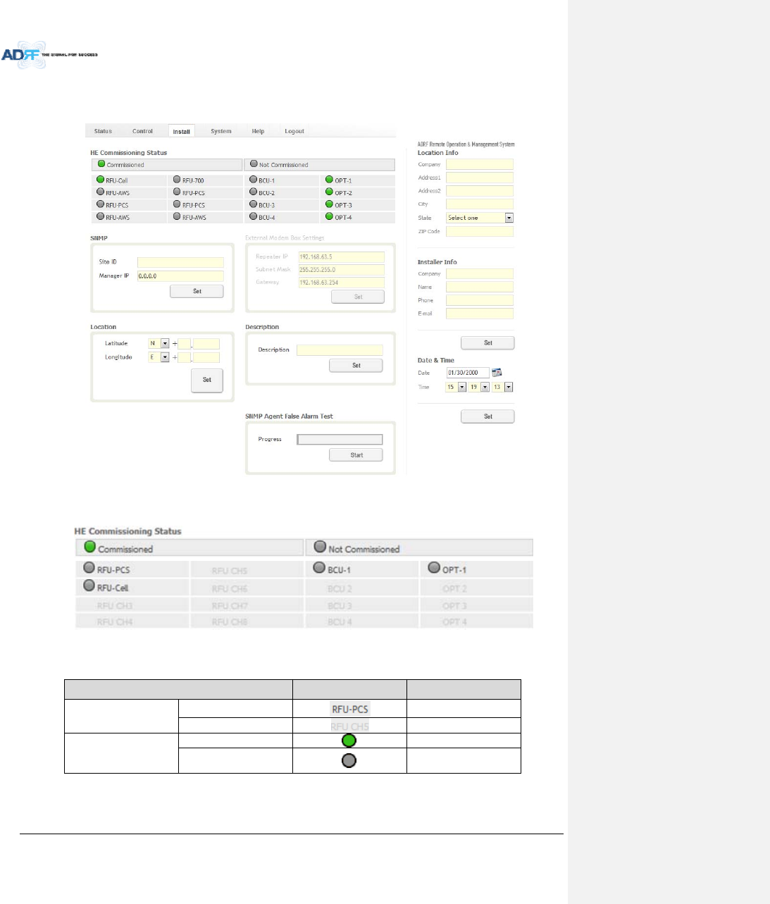
8.2.4.1 Install–NMS
Figure8‐60Install‐NMS
8.2.4.1.1 HECommissioningStatus
Figure8‐61HECommissioningStatus(Install–NMS)
Table8‐21DescriptionforHECommissioningStatus(Install–NMS)
StatusDisplayDescription
InstalledStatusPhysicallyInstalledTextisblack
PhysicallyNot‐InstalledTextisgray
CommissioningStatus
SuccessGreen
Failornot
commissionedGray
AdvancedRFTechnologies,Inc. 94
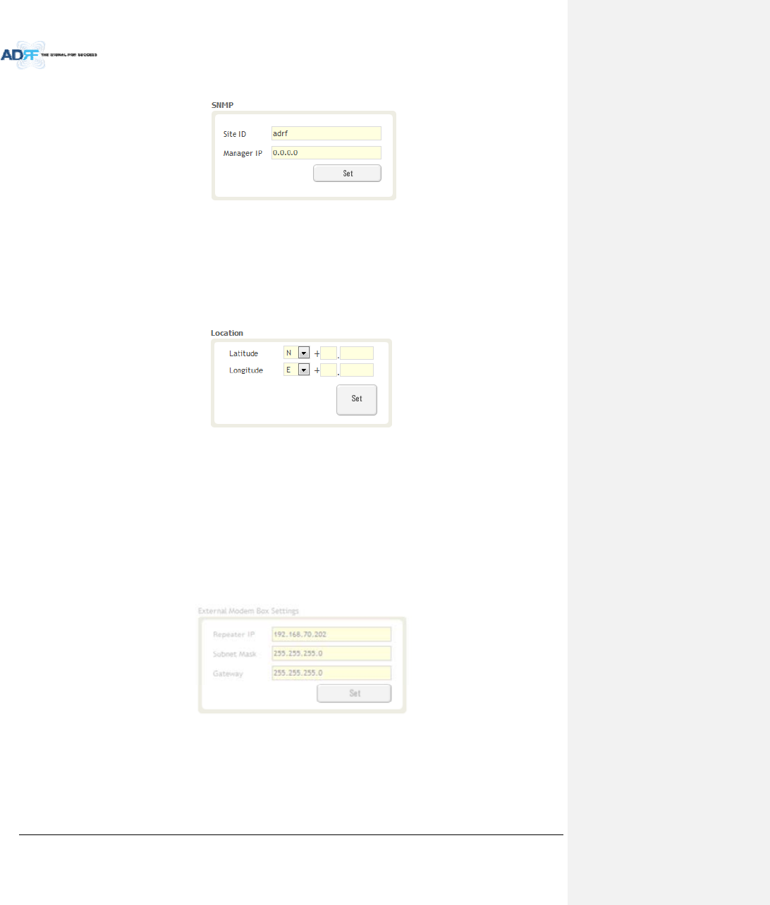
8.2.4.1.2 SNMP
Figure8‐62SNMP(Install–NMS)
TheSNMPsectionallowsyoutospecifytheSiteIDandManagerIP.TheSite‐IDisthecodethatisusedto
identifyaparticularmodule.TheManagerIPfieldiswheretheuserinputstheIPaddressoftheNOCsystemthat
isbeingusedtomonitortheSNMPtraps.
8.2.4.1.3 Location
Thissectionallowstheusertoinputthelatitudeandthelongitudeoftherepeater.
Figure8‐63LocationSetting(Install–NMS)
SelectNorSfromthedropdownmenuforLatitude
SelectEorWfromthedropdownmenuforLongitude
Inputthefirst3numbersofthelatitude/longitudeinthetextareaafterthe“+”andbeforethe“.”
Inputthelast6numbersofthelatitude/longitudeinthetextareaafterthe“.”
8.2.4.1.4 ExternalModemBoxSettings
ThissectionallowstheusertospecifyanalternativeIP,SubnetMask,andGatewaysettings.Thesesettings
areenabledwhentheHost/RemoteswitchissettotheRemoteposition.
Figure8‐64ExternalModemBoxSetting(Install–NMS)
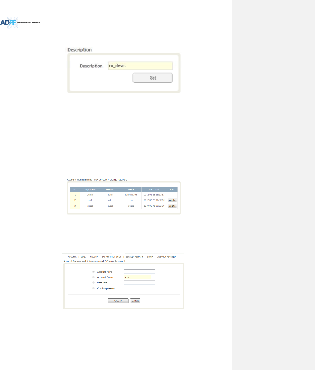
8.2.4.1.5 Description
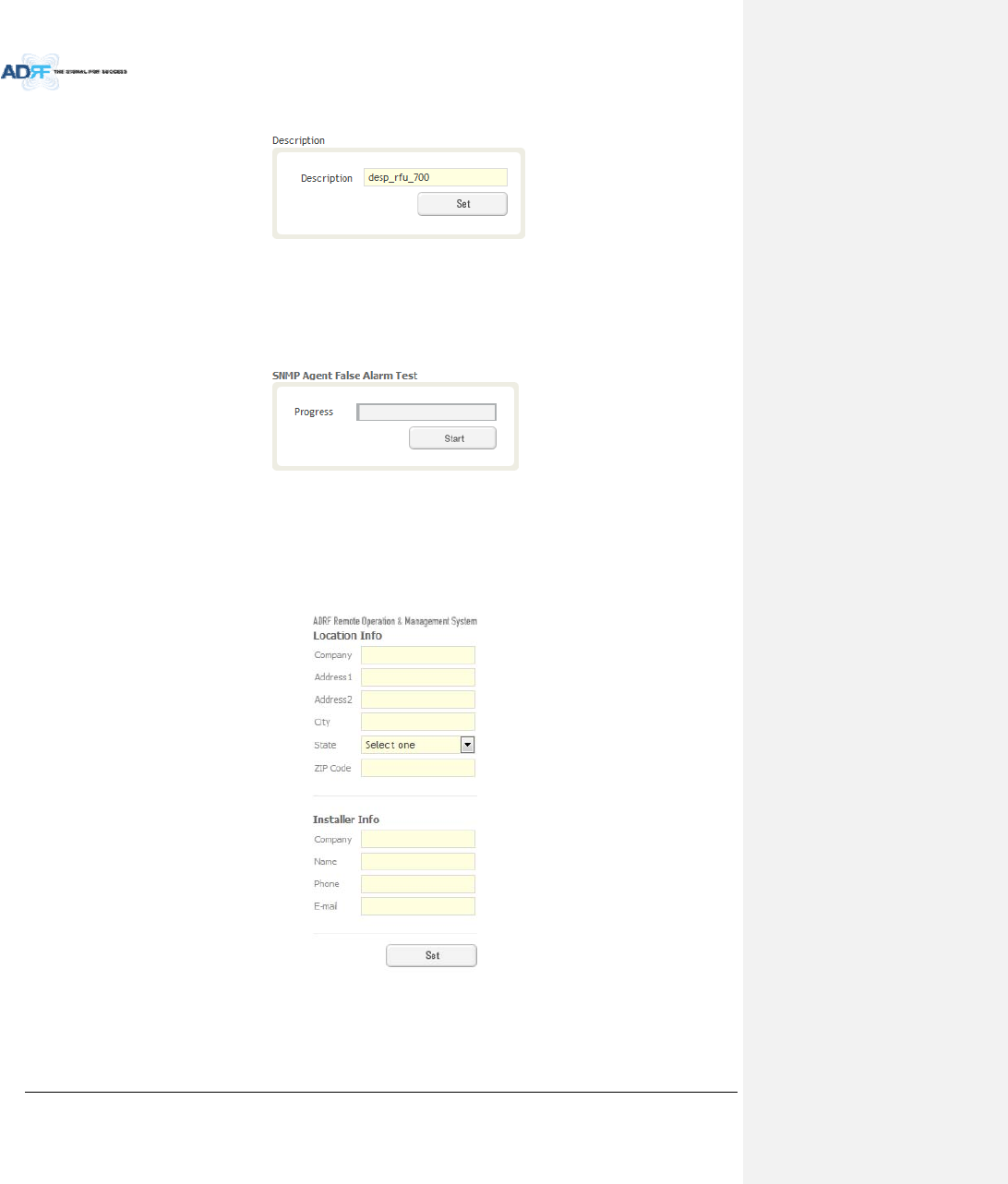
AdvancedRFTechnologies,Inc. 95
ThissectionallowstheusertosavethedescriptionofNMS.
Figure8‐65Description(Install–NMS)
8.2.4.1.6 SNMPAgentFalseAlarmTest
Thissectionallowstheusertogeneratebothsoftandhardfailalarms.Afteralarmsaregenerated,theNOC
canpolltheADXtoseeifalarmsarepresent.Allalarmsgeneratedduringthistestarefalsealarms.
Figure8‐66SNMPAgentFalseAlarmTest(Install–NMS)
8.2.4.1.7 LocationInfo/InstallerInfo
Thissectionallowstheusertospecifytheaddressoftherepeaterandalsotheinformationoftheinstaller.
Figure8‐67 LocationInfo/InstallerInfo(Install–NMS)
AdvancedRFTechnologies,Inc. 96
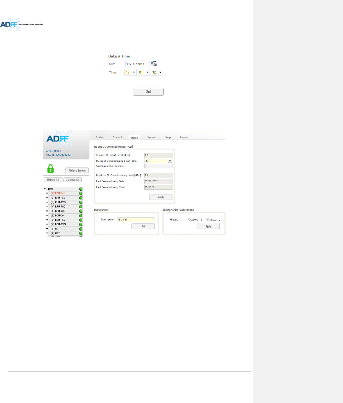
8.2.4.1.8 Date&Time
Thissectionallowstheusertospecifythecurrentdateandtime.
Figure8‐68Date&TimeSetting(Install–NMS)
8.2.4.2 Install–RFU
Figure8‐69Install‐RFU
AdvancedRFTechnologies,Inc. 97
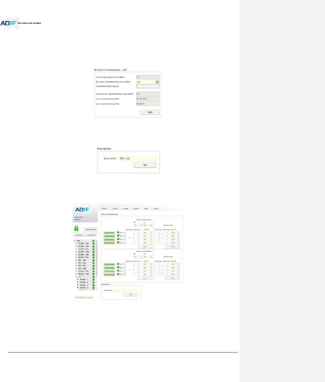
8.2.4.2.1 RFUCommissioning
ThissectionallowstheusertoperformRFUcommission.ToperformRFUcommissioning,selectaDLInput
CommissioningLevelfromthedropdownmenuandclickApply.Thecommissioningprogressisdisplayedonthe
CommissioningProgressbar.Anyerrors,warnings,andmessageswillappearviaapopupwindow.Pleasereferto
theADXInstallationGuidetodeterminetheproperRFUcommissioninglevels.
Figure8‐70RFUCommissioning(Install–RFU)
8.2.4.2.2 Description
ThissectionallowstheusertosetthedescriptionofRFU.
Figure8‐71Description(Install–RFU)
8.2.4.3 Install–OPT
Figure8‐72Install–OPT
8.2.4.3.1 OpticCommissioning
Thissectionwillallowtheusertoperformanyopticcompensationifitisnecessary.TheCommissioning
buttonwillturnorangeifopticcompensationisneeded.
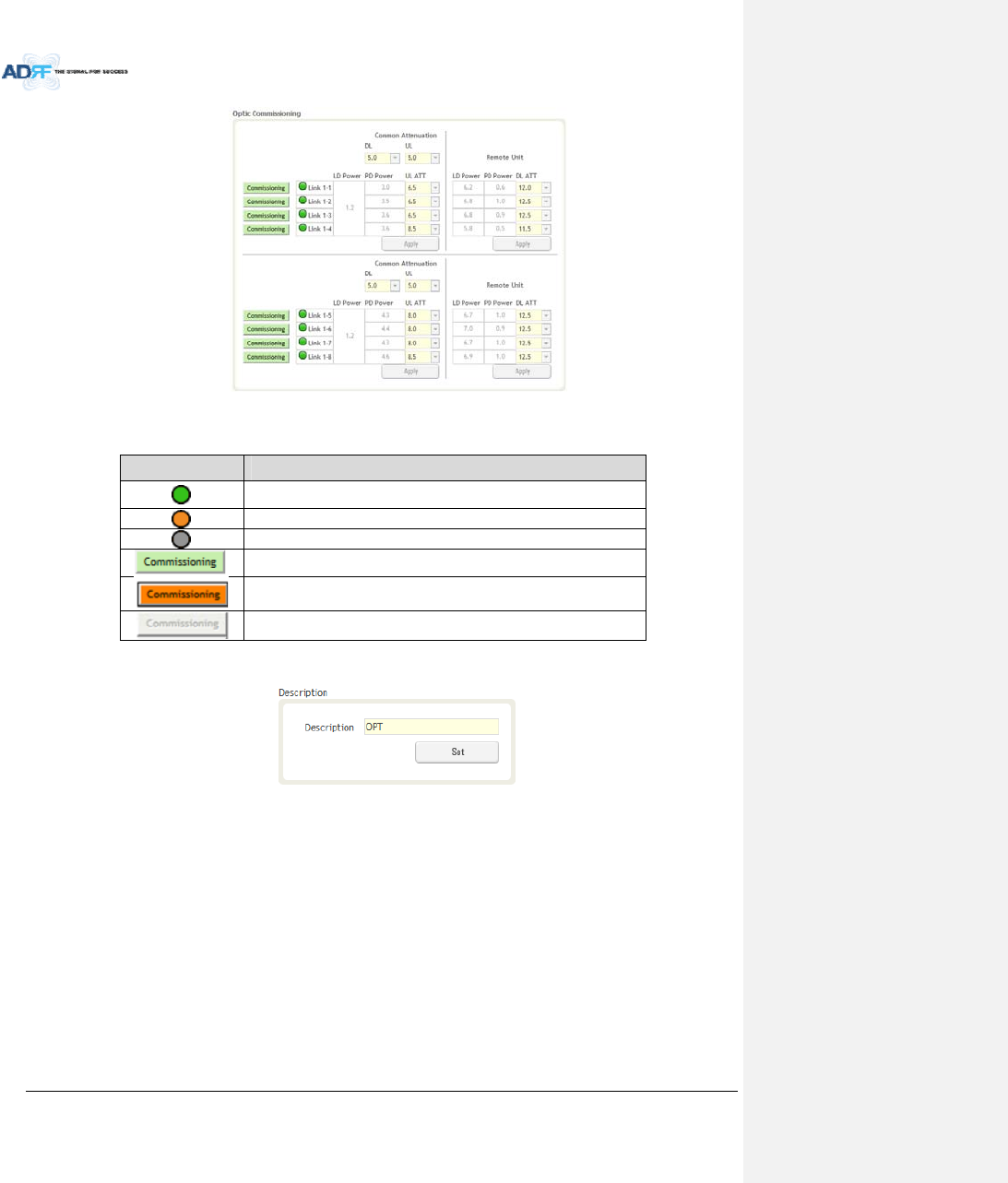
AdvancedRFTechnologies,Inc. 98
Figure8‐73Opticcontrol(Control–OPT)
Table8‐22DescriptionforOpticcontrol(Control–OPT)
Display&ControlDescription
Opticlossislessthan5dBo
Opticlossismorethan5dBo
NotconnectedtoaRU
Noopticlosscompensationisneeded.
Opticlosscompensationisneeded.
NotconnectedtoaRU
8.2.4.3.2 Description
ThissectionallowstheusertosavethedescriptionofOPT.
Figure8‐74Description(Install–OPT)
8.2.4.4 Install–RUHub
AdvancedRFTechnologies,Inc. 99
Figure8‐75Install‐RUHub
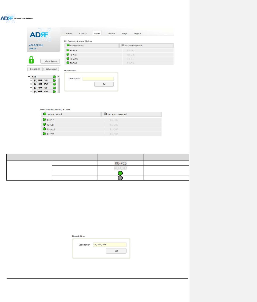
8.2.4.4.1 RUCommissioningStatus
Figure8‐76RUCommissioningStatus(Install‐RUHub)
Table8‐23DescriptionforRUCommissioningstatus
StatusDisplayDescription
InstalledStatusPhysicallyInstalledTextisblack
PhysicallyNot‐InstalledTextisgray
CommissioningStatusSuccessGreen
FailornotcommissionedGray
8.2.4.4.2 Description
ThissectionallowstheusertosavethedescriptionofRUHub.
Figure8‐77Description(Install‐RUHub)
8.2.4.5 Install–RemoteModule(MasterorSlaveRU)
AdvancedRFTechnologies,Inc. 100
Figure8‐78Install‐RemoteModule
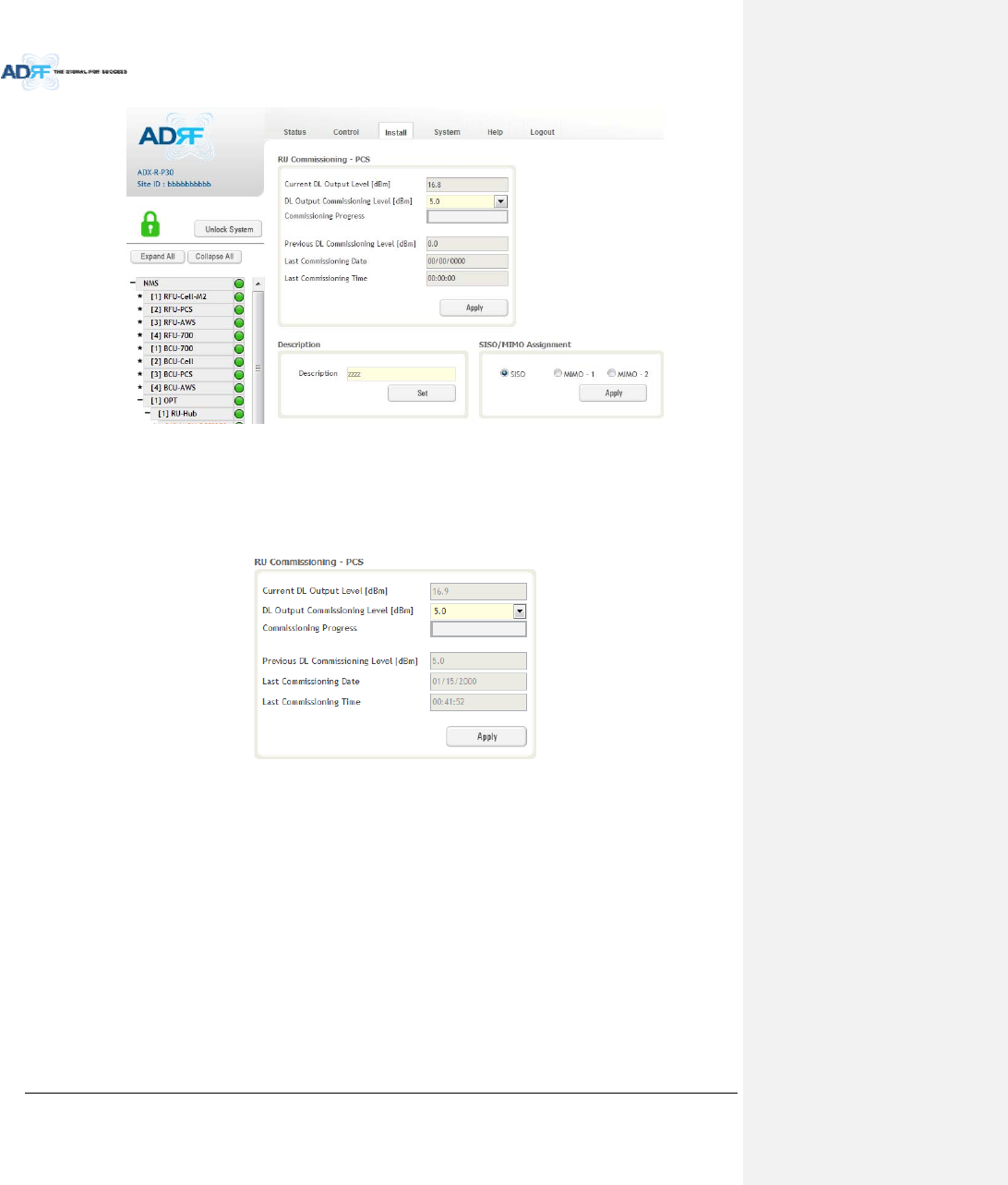
8.2.4.5.1 RUOutputCommissioning
ThissectionallowstheusertoperformRUcommission.ToperformRUcommission,selectaDLOutput
CommissioningLevelfromthedropdownmenuandthenclickApply.Thecommissioningprogressisdisplayedon
theCommissioningProgressbar.Anyerrors,warnings,andmessageswillappearviaapopupwindow.
Figure8‐79RUOutputCommissioning(Install‐RU)
AdvancedRFTechnologies,Inc. 101
8.2.4.5.2 Description
Thissectionallowstheusertosavethedescriptionofremotemodule.
Figure8‐80Description(Install‐RemoteModule)
8.2.5 System
TheSystemtaballowstheusertoperformfirmwareupdates,uploadcloseoutpackages,viewanychangesto
thesystem,backupexistingconfiguration,andadd/removeuseraccounts,andchangethelogincredentialsofthe
Administrator.
8.2.5.1 System:Account
8.2.5.1.1 System:Account‐AccountManagement(AdminOnly)
TheAccountManagementsectionallowstheAdministratortodeleteanyuser/guestaccount.Pleasenote
thattheAccountManagementsectionisonlyavailableifyouareloggedintothesystemastheAdministrator.To
deleteauser/guestaccountclickontheAccountManagementlinkandundertheDeletecolumn,clickonthe
deletebutton.
Figure8‐81AccountManagement
8.2.5.1.2 System:Account‐NewAccount(AdminOnly)
TheNewaccountsectionallowstheAdministratortocreateanewuser/guestaccount.Pleasenotethatthe
newaccountsectionisonlyavailableifyouareloggedintothesystemastheAdministrator.Tocreateanew
user/guestaccountclickonthenewaccountlinkandfillinthefieldshighlightedinyellowasshownbelow.
Figure8‐82NewAccount
AdvancedRFTechnologies,Inc. 102
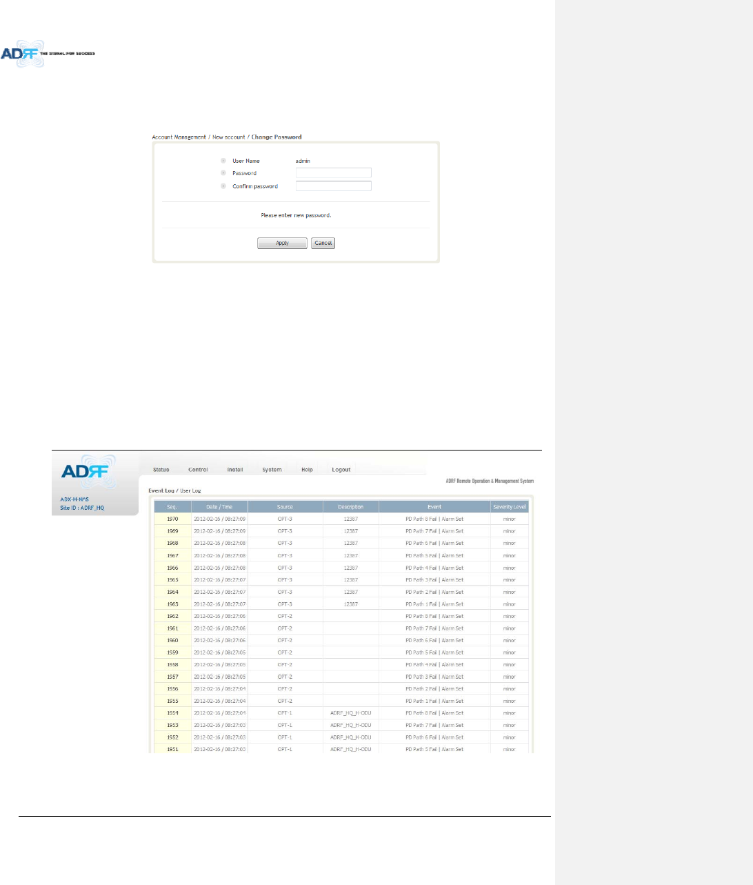
8.2.5.1.3 System:Account‐ChangePassword
TheChangePasswordsectionallowsthecurrentuserwhoisloggedintothesystemtochangetheirlogin
credentials.
Figure8‐83ChangePassword
8.2.5.2 System:Logs
8.2.5.2.1 System:Logs‐EventLog
Thissectiondisplayssystemeventsthathavetakenplace.TheEventLogdisplayswhohasmadethechanges,
thetimeanddateofwhentheeventtookplace,andwhatchangesweremadetothesystem.TheSystemLog
tracksthefollowingevents:
SystemInitiation
AlarmSet
AlarmClear
Figure8‐84EventLog
AdvancedRFTechnologies,Inc. 103
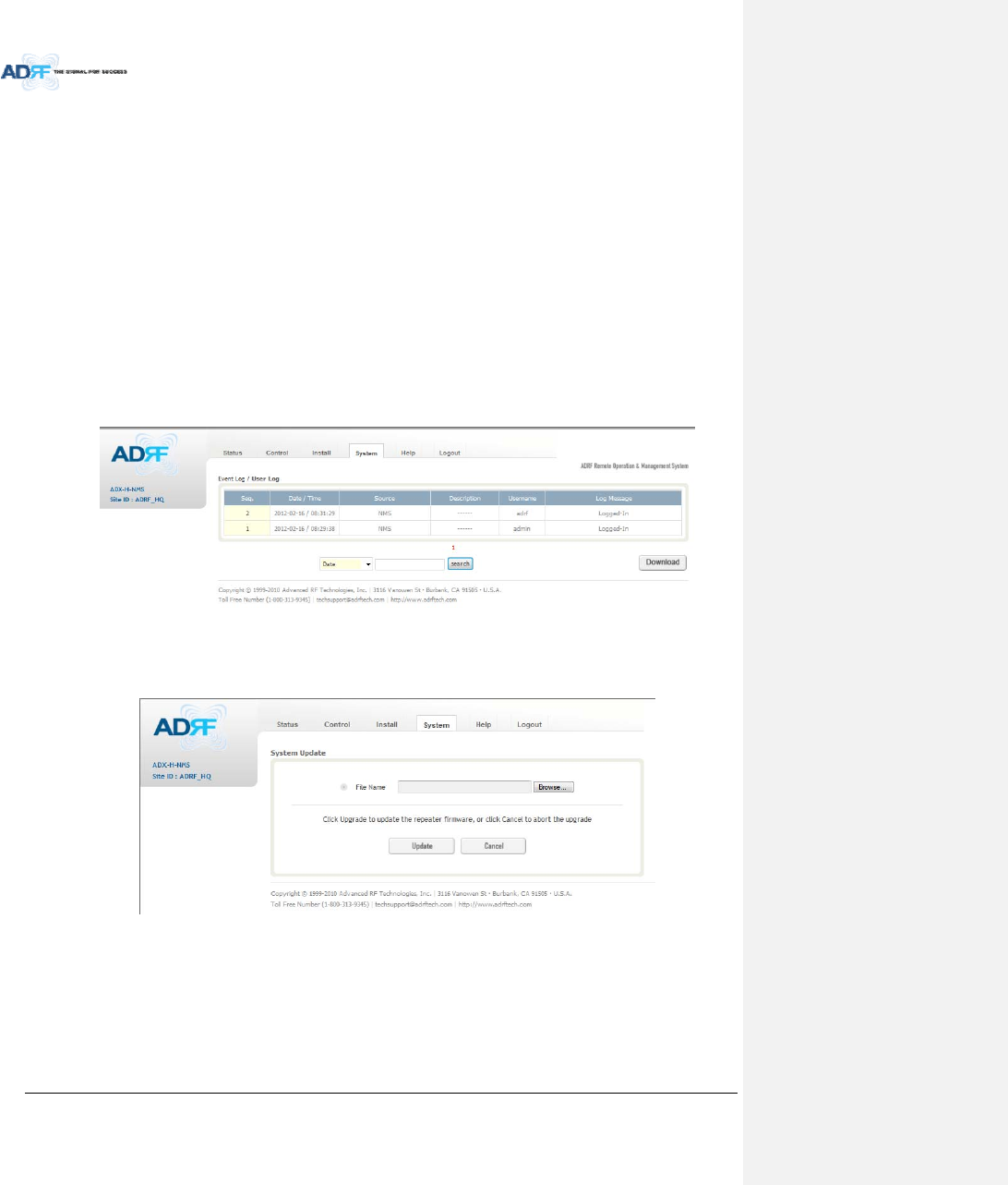
8.2.5.2.2 System:Logs‐UserLog
Thissectiontracksuseractivitywithinthesystem.TheUserLogdisplayswhohasmadethechanges,thetime
anddateofwhentheeventtookplace,andwhatchangesweremadetothesystem.TheUserLogtracksthe
followingitems:
Login/Logoutactivity
Changestogain/attenuation/outputvalues
Systemeventgeneratedbyuser(firmwareupdate,backup/resote,create/deleteaccount)
DASNavigationTreeLock/Unlock
Descriptionchange
Repeater/installerinformationchange
Settingdate/time
Figure8‐85UserLog
8.2.5.3 System:Update
Toperformafirmwareupdate,clickontheSystem:Updatetabandthefollowingscreenwillshowup.
Figure8‐86Systemupdate
Clickonthe‘Browse’buttonandlocatethefirmwarefile.
ClickontheUpdatebuttontoperformthefirmwareupdate.
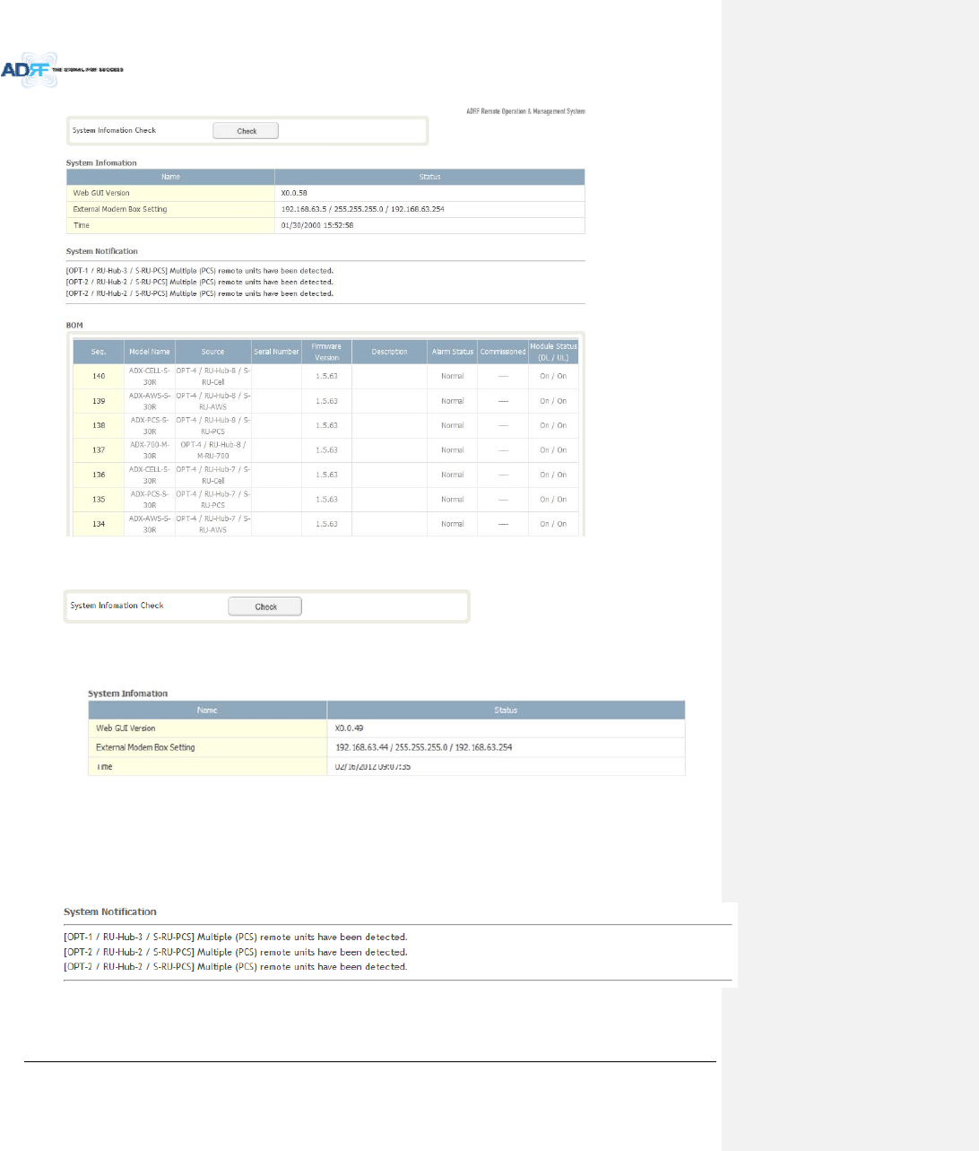
8.2.5.4 System:SystemInformation
8.2.5.4.1 System:SystemInformation
AdvancedRFTechnologies,Inc. 104
SystemInformationCheck
TheSystemInformationCheckbuttonwillchecktheADXconfiguationandreportpossiblediscrepancies.
SystemInformation
ThissectiondisplaysthegeneralsysteminformationoftheADXDAS.
Figure8‐87SystemInformation
SystemNotification
Thissectionisdisplayedonlywhenthefollowingconditionsarepresent:
‐ WhenmultipleremotemoduleswithsamefrequencybandexistinaRU.
‐ WhentheremotemoduledoesnotmatchwiththeRFUbeingused.
Figure8‐88SystemNotification
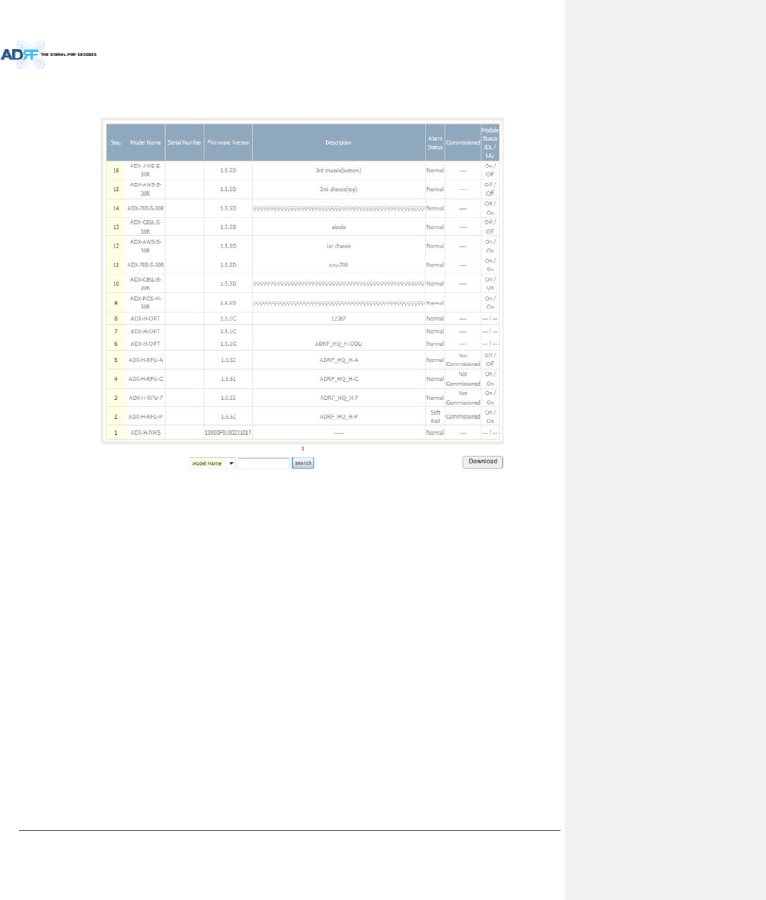
BOM
AdvancedRFTechnologies,Inc. 105
BOMdisplaysallpartsthatareconnectedtotheADX‐H‐NMS.
TheBOMcanbedownloadedasaCSVfilebyclickingthe‘Download’buttonatthebottomright.
Figure8‐89Billofmaterial
AdvancedRFTechnologies,Inc. 106
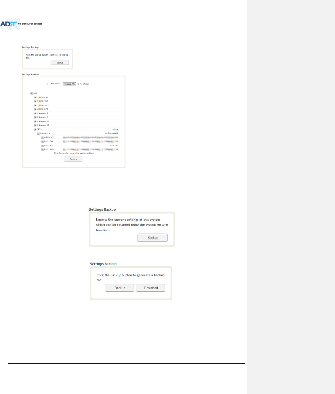
8.2.5.5 System:Backup/Restore
SettingsBackup
ClickingtheBackupwillcreateatemporarybackupfilestoredinsideoftheADX.Oncethefileiscreated,itwill
needtobedownloadedtoacomputer.Adownloadbuttonwillappearafterthebackupfilehasbeencreated.If
theADXispowercycledorrebooted,thenthetemporarybackupfilewillbelost.Werecommenddownloading
thebackupfileimmediatelyafterithasbeencreated.ClickontheDownloadbuttontodownloadthebackupfile.
Figure8‐90SettingBackup(Before)
Figure8‐91SettingBackup(After)
AdvancedRFTechnologies,Inc. 107
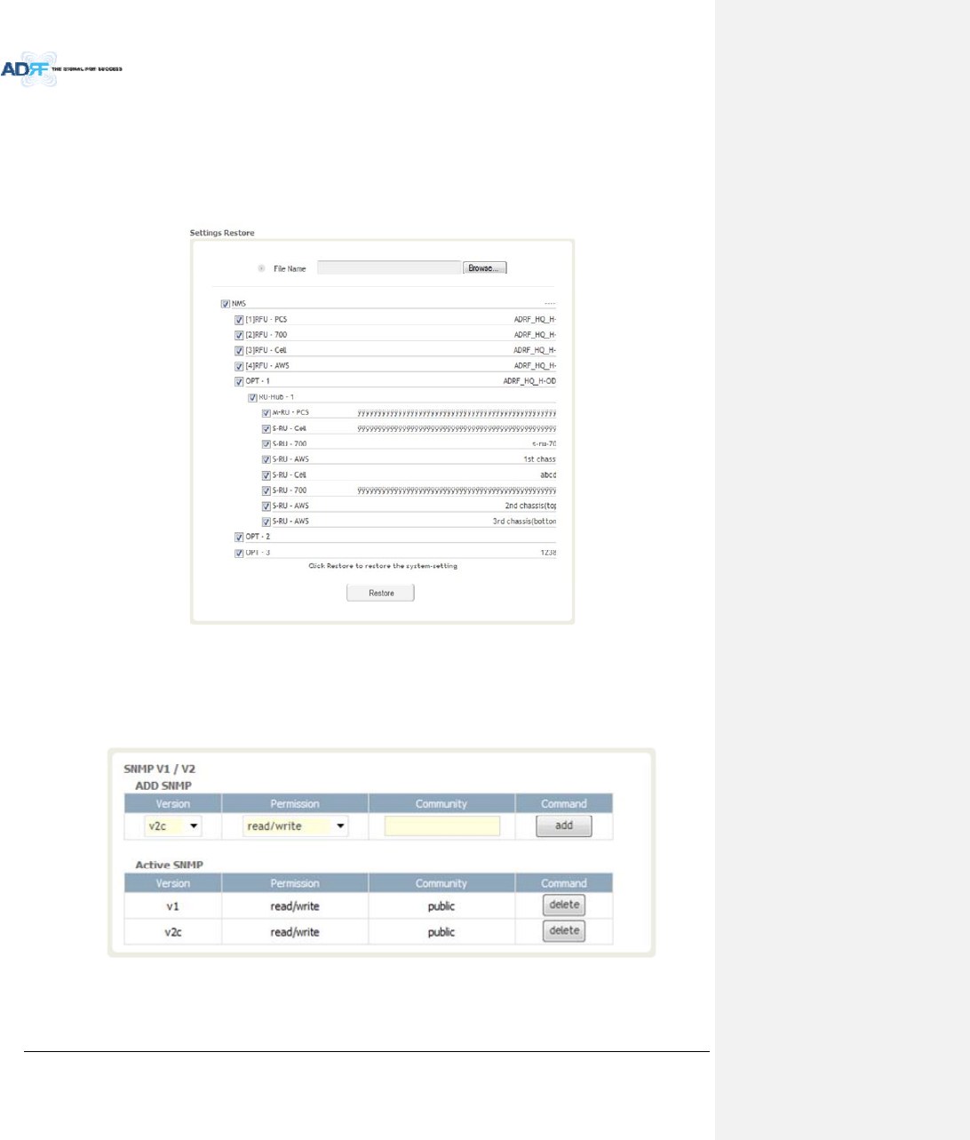
SettingRestore
Restorefunctioncanbeusedtorestorethesavedsettingsfromthebackupfile.Oncethebackupfileisloaded,
thetreeinthefigurebelowwillappear.Checktheboxesofthemodulesthatyouwouldliketorestoreandthen
clickthe“Restore”buttonatthebottomonthissection.
WerecommendcreatinganewbackupfileifaddingorremovingmodulesfromtheADX.Discrepancies
betweenthebackupfileandtheexistingtreecouldcauserestoreerrors.
Figure8‐92SettingRestore
8.2.5.6 System:SNMP
SNMPV1/V2
ThissectionallowsyoutoaddcommunitystringsforSNMPv1andv2.
Figure8‐93SNMPV1/V2
AdvancedRFTechnologies,Inc. 108
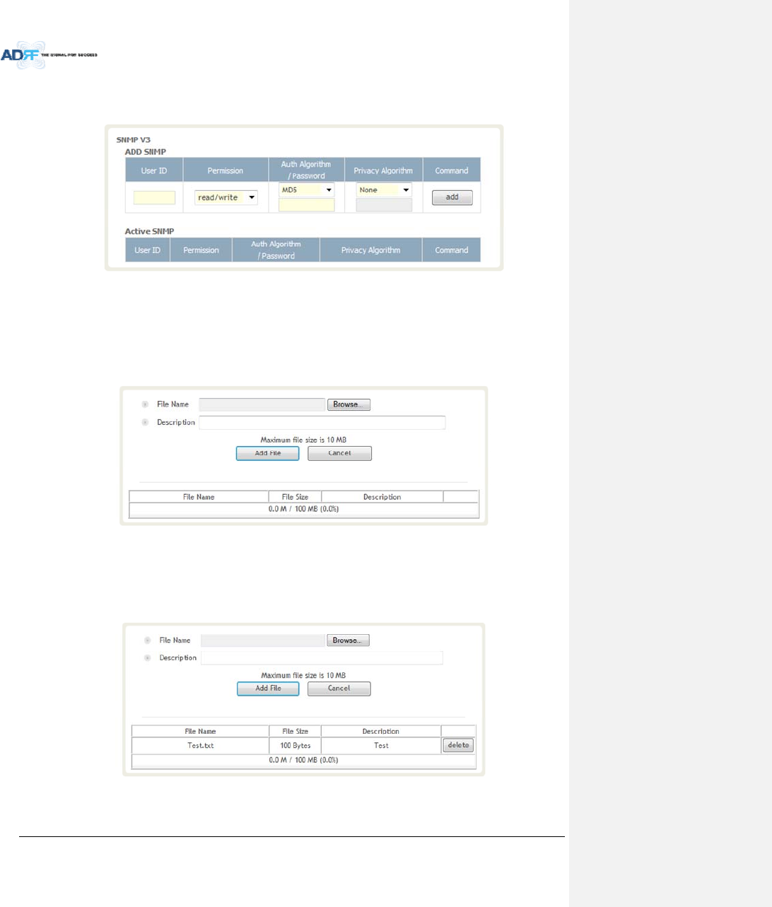
SNMPV3
ThissectionallowstheusertoaddaccountsforSNMPv3.
Figure8‐94SNMPV3
8.2.5.7 System:CloseoutPackage
ThecloseoutpackagesectionwillallowtheusertouploaddocumentstotheADX‐H‐NMS.Themaximumfile
sizeforeachuploadislimitedto10MB.Thetotalamountofspaceavailableforuploadingdocumentis100MB.
Pleasedonotusethissectionastheprimarystoragelocationofyourdocuments.Documentsmaybecome
unavailableifthesystemgoesdown.
Figure8‐95System‐CloseoutPackage
Touploaddocumentstothemodule,clickonthe“Browse”buttonandlocatethefilethatyouwouldliketo
upload,thenenterinaDescriptionofthefilebeinguploaded.Afterwards,clickonthe“AddFile”buttontoupload
thefile.Belowiswhatyouwillseeafterthefileupload.Todeletethefile,clickonthedeletebuttonlocatedinthe
lastcolumn.
Figure8‐96System‐CloseoutPackageafterthefileupload

AdvancedRFTechnologies,Inc. 109
8.2.6 Help
Ifaninternetconnectionisavailable,clickingontheHelpTabwillredirecttheusertoourTechnicalSupport
page.
Figure8‐97Help
8.2.7 Logout
ClickingtheLogoutbuttonwilllogthecurrentuseroffthesystem.
8.3 GuestMode
Whenloggingintothesystemasaguest,theguestwillonlyhaveread‐onlyprivilegesandwillnotbeableto
makeanychangestothesystem.
AdvancedRFTechnologies,Inc. 110
9. SYSTEMSPECIFICATION
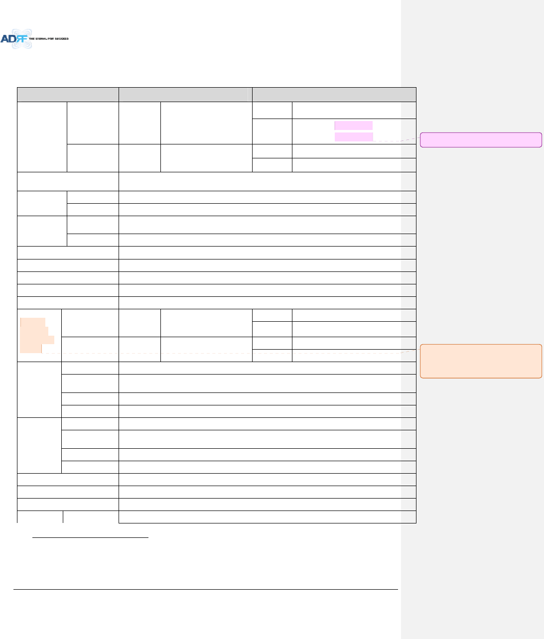
9.1 SpecificationforPS78,SMR
ParametersPS78SMR
Frequency
DownlinkP7758‐775MHz
S8851‐869MHz
S9929‐930MHz
935‐940MHz
UplinkP7788‐805MHz
S8806‐824MHz
S9896‐901MHz
InputPowerRange0~+25dBm
Gain
Downlink5~30dB,0.5dBstep,ATTrange:0~25dB
Uplink‐5~30dB,0.5dBstep,ATTrange:0~35dB
Maximum
Output
Power1
Downlinkat
RU30dBm±2dB
UplinkatHE‐15dBm±2dB
NoiseFigure<10dB@maximumgain
VSWR<1:1.5
OpticalLoss0~5dBo
SystemDelay<2us
SpuriousMeetFCCrules,3GPPTS36.104,3GPP2C.S0010‐C
Nominal
Band/BW
forIndustry
Canada
DownlinkP7749‐781MHz
S8840‐880MHz
S9925‐949MHz
UplinkP7782‐831MHz
S8811‐834MHz
S9887‐911MHz
Dimension
(WXDXH)
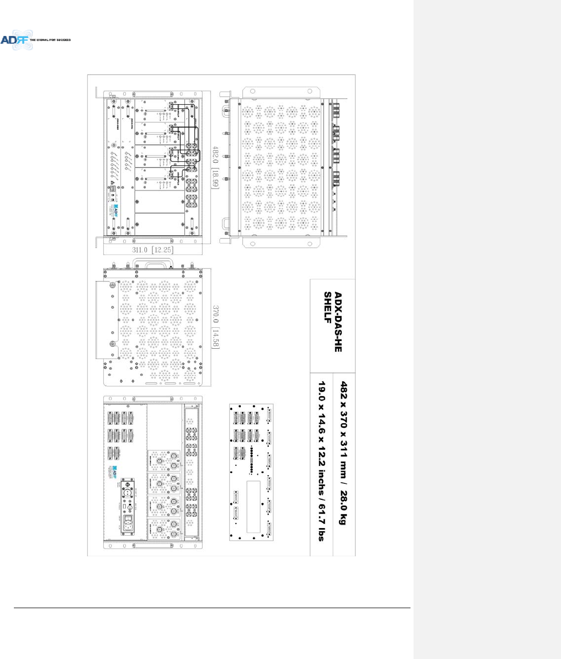
Head‐EndShelf19.0x14.6x12.2inches(482x370x311mm)
Remote‐Unit
Shelf19.0x12.9x10.5inches(482x328.2x266.5mm)
MasterRU11.8x9.8x4.5inches(300x249.6x114.5mm)
SlaveRU11.8x9.8x3.7inches(300x249.6x94.5mm)
Weight
Head‐EndShelf83.7lbs(38.0Kg)@4RFU,CHC‐H,PSUandNMS
Remote‐Unit
Shelf61.0lbs(27.7kg)@1masterRU,3SlaveRU
MasterRU13.2lbs(6.0kg)
SlaveRU11.7lbs(5.3kg)
OperatingTemperature14‐122F(‐10‐50°C)
OperatingHumidity5~90%RH
PowerInput110/220V,50‐60Hz,24Vor‐48VDC(optional)
PowerHead‐End52W@4RFU,1ODURackwith2ODUsandNMS
1TheManufacturer'sratedoutputpowerofthisequipmentisforsinglecarrieroperation.Forsituationswhen
multiplecarriersignalsarepresent,theratingwouldhavetobereducedby3.5dB,especiallywheretheoutput
signalisre‐radiatedandcancauseinterferencetoadjacentbandusers.Thispowerreductionistobebymeansof
inputpowerorgainreductionandnotbyanattenuatorattheoutputofthedevice
메모 [H5]: 주파수범위수정15/05/19
메모 [Y6]: 실제로측정하셔서
기입요청합니다.
15/02/03
AdvancedRFTechnologies,Inc. 111
consumptio
n28W@1RFU,,1ODURackwith2ODUsandNMS
Remote‐Unit60W53W
NetworkManagementSystemEthernet(RJ45)
RF
connector
Head‐EndN‐type(Female)
Remote‐UnitN‐type(Female)
Input/outputImpedance50
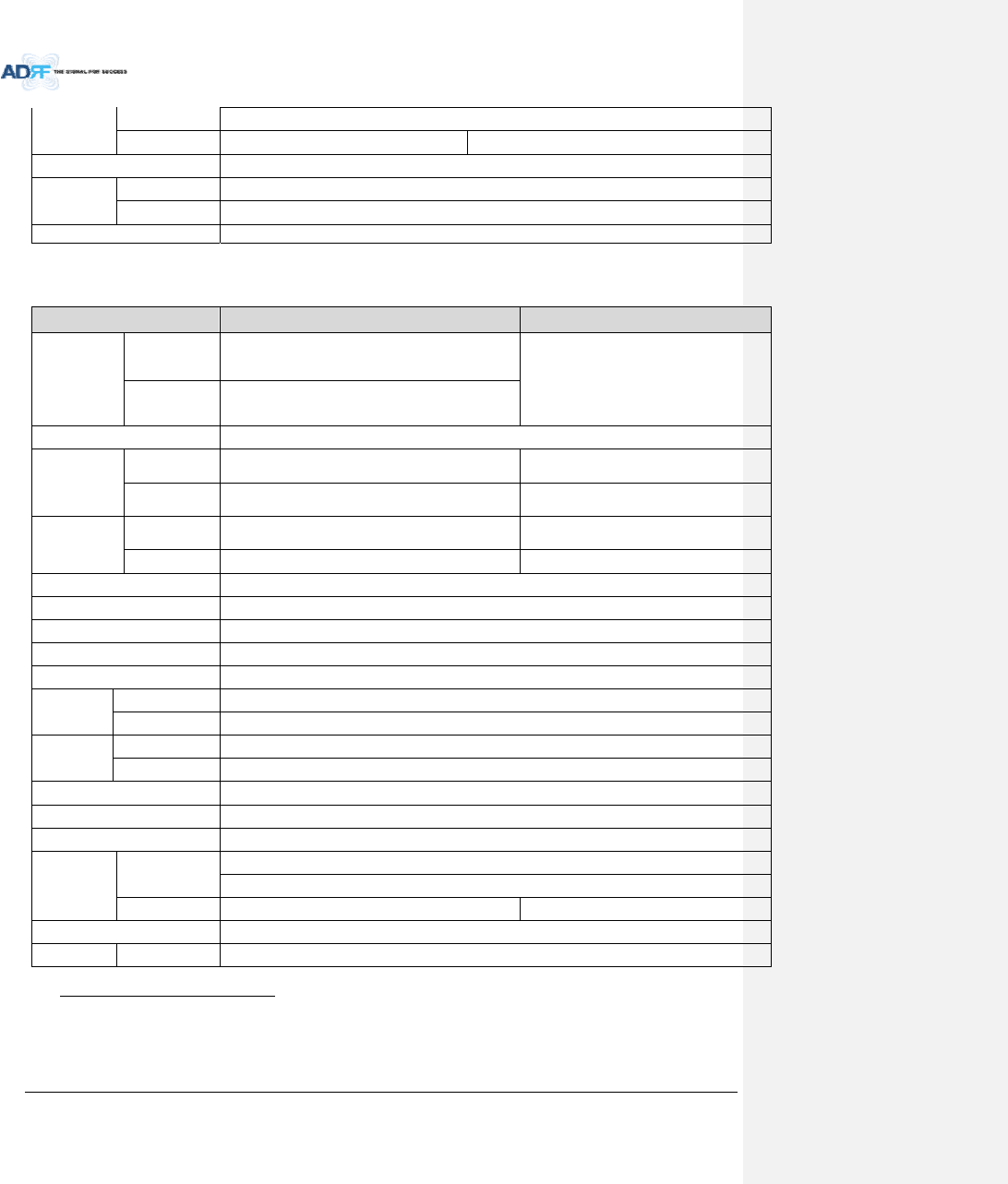
9.2 SpecificationforVU,BT
ParametersBTTBD
Frequency
Downlink2496‐2690MHz
(BRSTDD)
Uplink2496‐2690MHz
(BRSTDD)
InputPowerRange‐15~+37dBm
Gain
Downlink0~52dB,0.5dBstep,
ATTrange:0~52dB
Uplink‐5~30dB,0.5dBstep,
ATTrange:0~35dB
Maximum
Output
Power2
Downlinkat
RU37dBm±2dB
UplinkatHE‐15dBm±2dB
NoiseFigure<10dB@maximumgain
VSWR<1:1.5
OpticalLoss0~5dBo
SystemDelay<2us
SpuriousMeetFCCrules,3GPPTS36.104,3GPP2C.S0010‐C
Dimension
(WXDXH)
MasterRU11.8x9.8x4.5inches(300x249.6x114.5mm)
SlaveRU11.8x9.8x3.7inches(300x249.6x94.5mm)
Weight
MasterRU13.2lbs(6.0kg)
SlaveRU11.7lbs(5.3kg)
OperatingTemperature14‐122F(‐10‐50°C)
OperatingHumidity5~90%RH
PowerInput110/220V,50‐60Hz,24Vor‐48VDC(optional)
Power
consumptio
n
Head‐End52W@4RFU,1ODURackwith2ODUsandNMS
28W@1RFU,1ODURackwith2ODUsandNMS
Remote‐Unit87W
NetworkManagementSystemEthernet(RJ45)
RFHead‐EndN‐type(Female)
2TheManufacturer'sratedoutputpowerofthisequipmentisforsinglecarrieroperation.Forsituationswhen
multiplecarriersignalsarepresent,theratingwouldhavetobereducedby3.5dB,especiallywheretheoutput
signalisre‐radiatedandcancauseinterferencetoadjacentbandusers.Thispowerreductionistobebymeansof
inputpowerorgainreductionandnotbyanattenuatorattheoutputofthedevice
AdvancedRFTechnologies,Inc. 112
connectorRemote‐UnitN‐type(Female)
Input/outputImpedance50
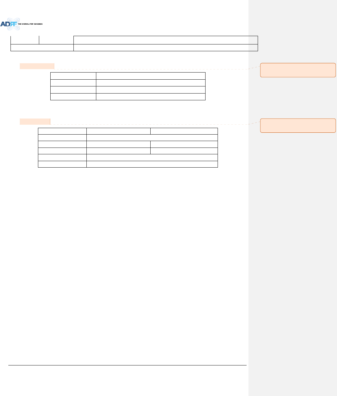
9.3 FCCCertification
ItemFCCCertification
ADX‐R‐SMRPart20,Part90
ADX‐R‐78PPart90
ADX‐R‐BTPart20
10. ANTENNASPECIFICATIONS
10.1 OmniAntenna
Frequency698‐960MHz1710‐2690MHz
PolarizationVertical
Gain2dBi3dBi
VSWR<1.7:1<1.5:1
Impedance50
PowerRating50W
Note.
Pleasenotethatintegrators,end‐usersorinstallersshouldnotusetheantennawithmoregainthan3dBi(For
Model:ADX‐R‐BT),2dBi(ForModel:ADX‐R‐SMR,ADX‐R‐78P)tomeettheRFexposurerequirement.
Part90.635requirement
AntennasmustbeinstalledinaccordancewithFCC90.635.With2dBigainantennastheheightoftheantenna
aboveaverageterrain(HAAT)ispermittedover1372m.Fordifferentgainantennasrefertotherelevantrules.
Part90.219requirement
Theradiatedpowermustbelimitedto1W.Therefore,thisdevicemeetthe90.219(e)(1)5WERPlimitation
requirement.
PriortoequipmentusetheservicemustberegisteredwiththeFCC.ThiscanbedonethroughtheFCC’swebsiteat
https://signalboosters.fcc.gov/signal‐boosters
메모 [Y7]: FCCpart 명기
15/02/03
메모 [Y8]: 안테나규격추가
15/02/03
AdvancedRFTechnologies,Inc. 113
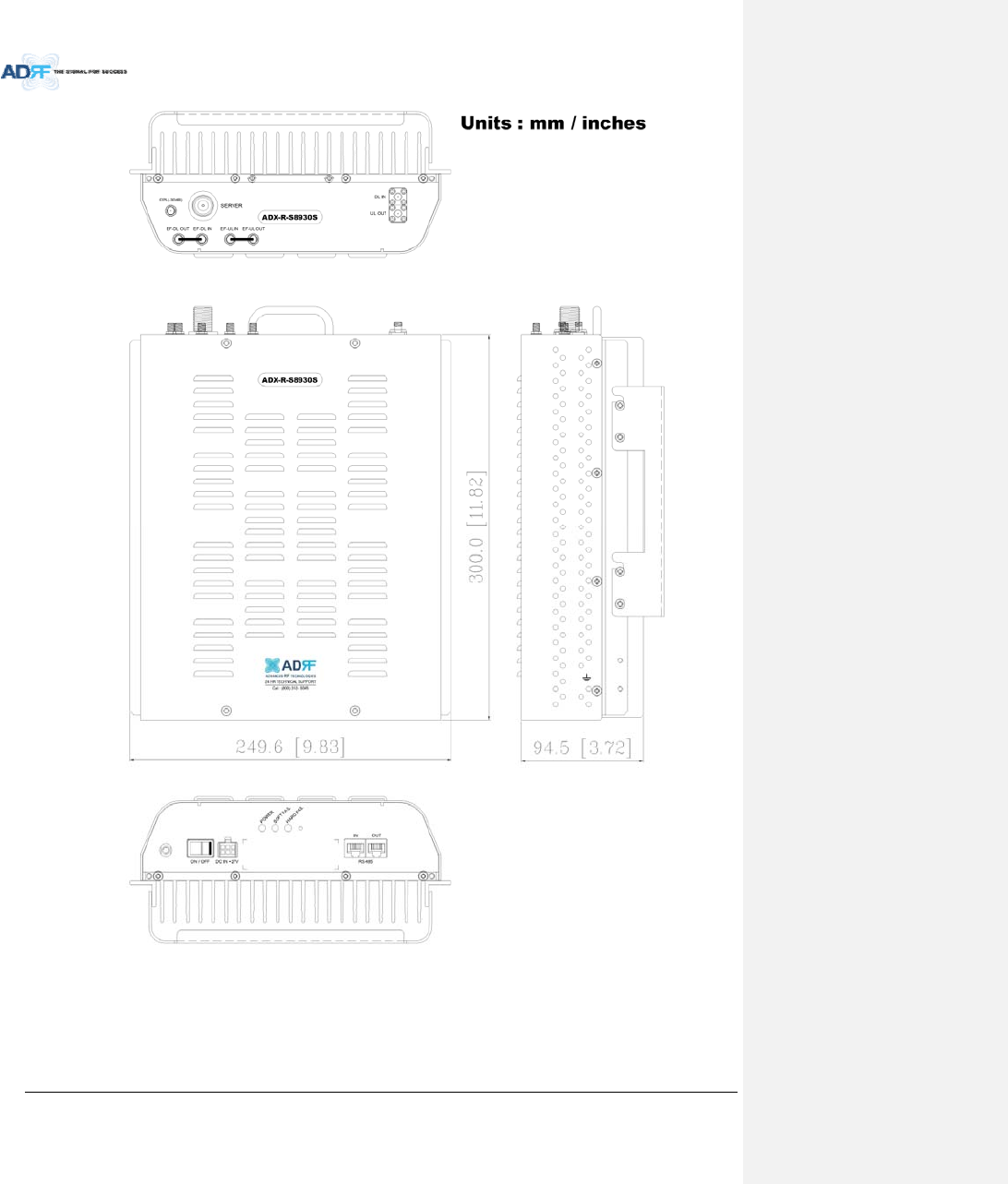
11. MECHANICALDRAWING
Figure11‐1HEDrawing
AdvancedRFTechnologies,Inc. 114
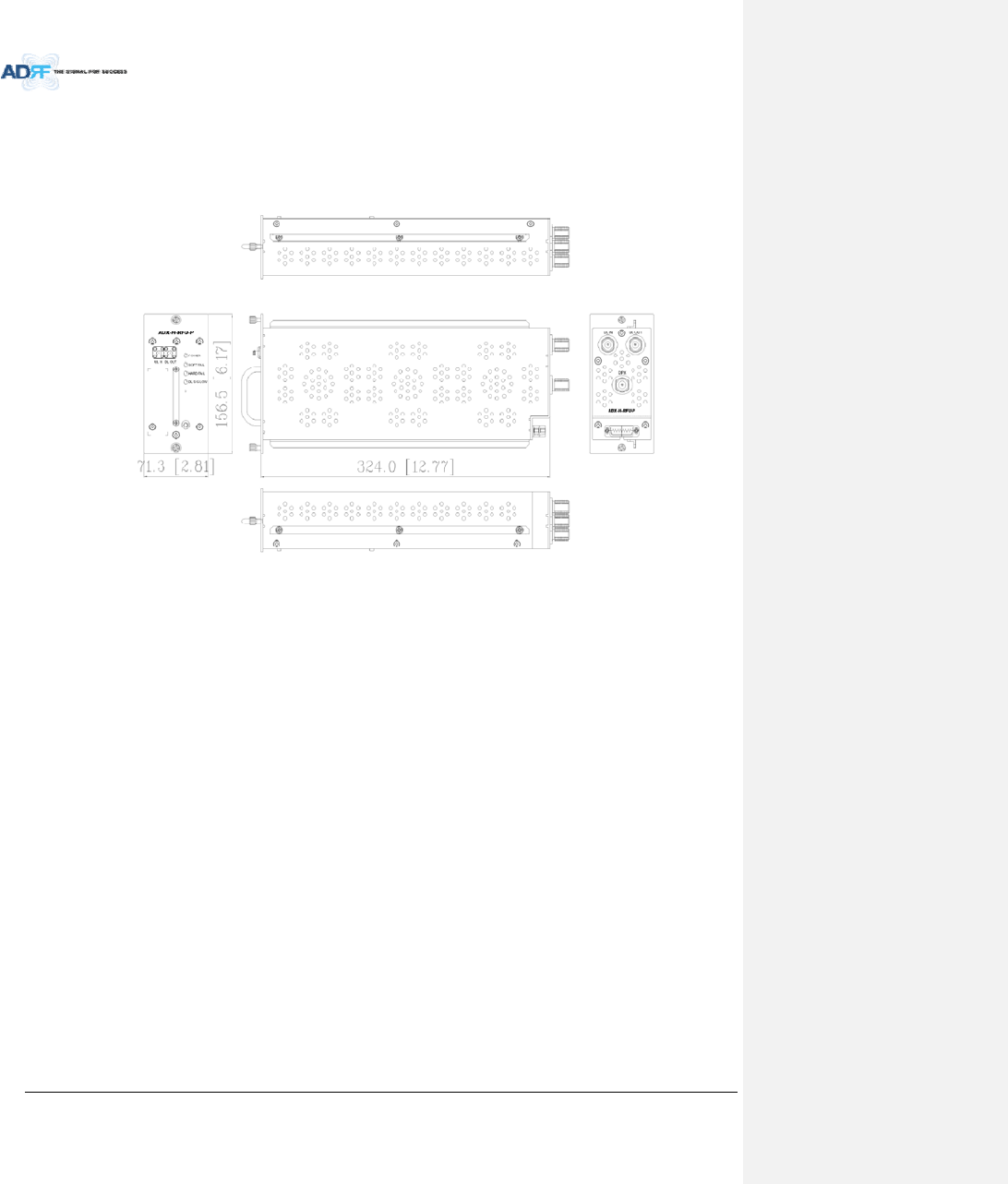
Figure11‐2RFUDrawingforSMR/PS
AdvancedRFTechnologies,Inc. 115
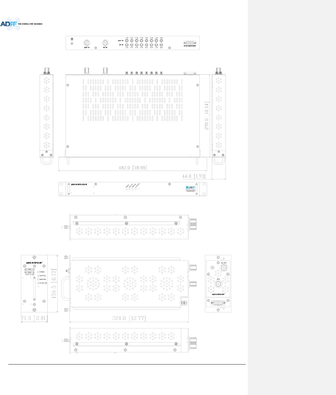
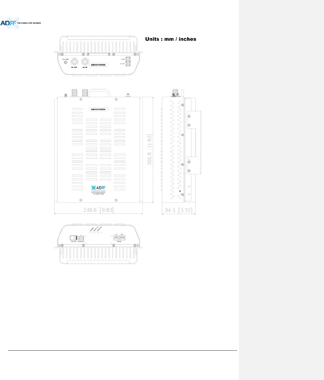
Figure11‐3RFUDrawingforVU
AdvancedRFTechnologies,Inc. 116
Figure11‐4RFUDrawingforBT
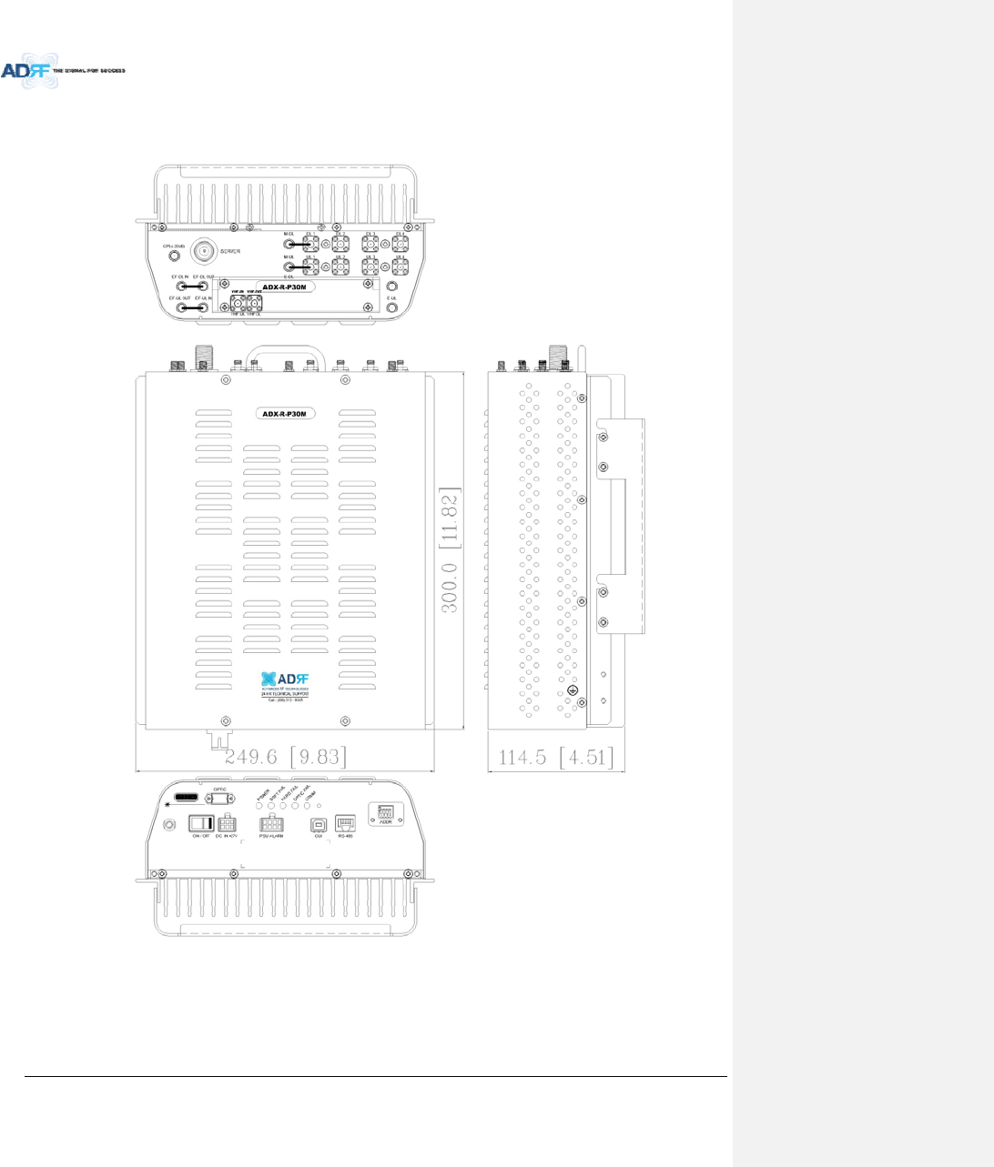
Figure11‐5MasterRUDrawingforPS
AdvancedRFTechnologies,Inc. 117
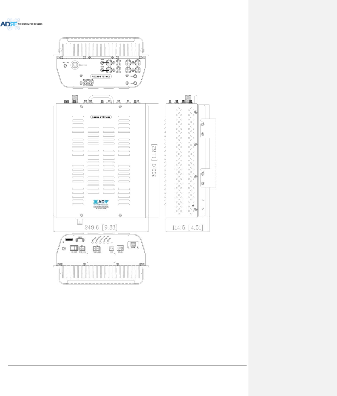
Figure11‐6MasterRUDrawingforBT
AdvancedRFTechnologies,Inc. 118
Figure11‐7SlaveRUDrawingforSMR
AdvancedRFTechnologies,Inc. 119
Figure11‐8SlaveRUDrawingforVU
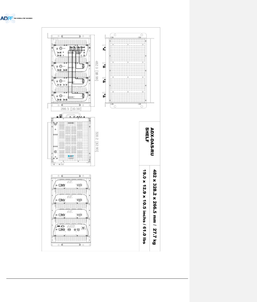
AdvancedRFTechnologies,Inc. 120
Figure11‐9RURackShelfDrawing