ADRF KOREA ADX-R-78P DAS (Distributed Antenna System) User Manual Rev3 Part1
ADRF KOREA, Inc. DAS (Distributed Antenna System) Rev3 Part1
Contents
- 1. User Manual Rev3_Part1
- 2. User Manual Rev3_Part2
User Manual Rev3_Part1
AdvancedRFTechnologies,Inc. i
ADXDASUserManual
3116WestVanowenSt.
Burbank,CA91505
Tel:818‐840‐8131
Fax:818‐840‐8138
www.adrftech.com

AdvancedRFTechnologies,Inc. ii
Informationinthisdocumentissubjecttochangewithoutnotice.
AdvancedRFTechnologies,Inc.1996‐2013.
Allrightsreserved.
Pleasesendcommentsto:
E‐Mail:info@adrftech.com
Phone: (818)840‐8131
(800)313‐9345
Fax: (818)840‐8138
Address:
AdvancedRFTechnologies,Inc.
Attention:TechnicalPublicationsDepartment
3116VanowenSt.
Burbank,CA91505
USA
www.adrftech.com
AdvancedRFTechnologies,Inc. iii
RevisionHistory
ChangeList
VersionChangelistContents
VersionAuthorDescriptionsDate

AdvancedRFTechnologies,Inc. iv
TableofContents
1.Introduction......................................................................................................................................................14
1.1Highlights...................................................................................................................................................14
1.2ADXDASQuickView..................................................................................................................................15
1.2.1HEQuickView....................................................................................................................................15
1.2.215
1.2.3RUQuickView....................................................................................................................................16
1.3WarningsandHazards...............................................................................................................................17
2.BlockDiagram...................................................................................................................................................21
2.1ADXDASBlockDiagram.............................................................................................................................21
2.2ADXDASTopology.....................................................................................................................................22
2.3SISOConfiguration.....................................................................................................................................23
2.4ADX‐DASScalability...................................................................................................................................24
3.ADXOverview...................................................................................................................................................25
3.1HeadEnd....................................................................................................................................................25
3.1.1NMS(NetworkManagementSystem)................................................................................................26
3.1.1.1LEDs..........................................................................................................................................26
3.1.1.2EthernetPort............................................................................................................................27
3.1.1.3Host/RemoteSwitch.................................................................................................................27
3.1.1.4HEView/RUViewSwitch..........................................................................................................27
3.1.2RFU(ADX‐H‐RFU‐x).............................................................................................................................28
3.1.2.1LEDs..........................................................................................................................................29
3.1.2.2RFPorts.....................................................................................................................................29
3.1.2.3CommunicationPort.................................................................................................................29
3.1.3ChannelCombiner(ADX‐H‐CHC)........................................................................................................29
3.1.3.1RFports.....................................................................................................................................30
3.1.3.2RFports.....................................................................................................................................30
3.1.4OpticDistributionUnit(ADX‐H‐ODU+ADX‐RACK‐ODU)....................................................................30
3.1.4.1LEDs..........................................................................................................................................31
3.1.4.2RFPorts.....................................................................................................................................31
3.2RemoteUnit...............................................................................................................................................32
3.2.1ADX‐R‐x3xM(MasterRU)...................................................................................................................33
3.2.1.1LEDs..........................................................................................................................................33
3.2.1.2RFPorts.....................................................................................................................................34
3.2.1.3OpticPort..................................................................................................................................35
3.2.1.4PowerOn/OffSwitch&DCINPort...........................................................................................35
3.2.1.5PSUAlarmPort.........................................................................................................................35
3.2.1.6GUIPort....................................................................................................................................35

AdvancedRFTechnologies,Inc. v
3.2.1.7RS‐485Port...............................................................................................................................35
3.2.1.8ADDR.........................................................................................................................................36
3.2.2ADX‐R‐xxxS/ADX‐R‐BTxxS/ADX‐R‐VU25S(SlaveRU)..........................................................................37
3.2.2.1LEDs..........................................................................................................................................37
3.2.2.2RFPorts.....................................................................................................................................38
3.2.2.3PowerOn/OffSwitch&DCINPort...........................................................................................39
3.2.2.4RS‐485Port...............................................................................................................................39
3.2.3RUPowerSupplyOptions...................................................................................................................39
3.2.3.1ADX‐R‐ADP(RUPowerAdapter)...............................................................................................39
3.2.3.2ADX‐R‐PSU(RUPowerSupplyUnit)..........................................................................................39
4.CableConnection..............................................................................................................................................41
4.1HeadEndConnectionDiagrams................................................................................................................42
4.1.1Front/RearHeadEndConnectionViewwithOptionalBCUunit........................................................42
4.1.2RearHeadEndConnectionViewwith(4)OPT‐8units.......................................................................43
4.2RemoteUnitConnectionDiagrams...........................................................................................................44
4.3RemoteUnitw/4‐WayCombiner(ADX‐R‐4WS).......................................................................................45
5.Mountingmethod.............................................................................................................................................46
5.1HeadEnd....................................................................................................................................................46
5.1.1RackMount........................................................................................................................................46
5.1.2WallMount.........................................................................................................................................
47
5.2RemoteUnit...............................................................................................................................................48
5.2.1RackMount........................................................................................................................................48
5.2.2WallMount.........................................................................................................................................49
5.2.2.1RemoteUnitusingRUChassis(ADX‐R‐CHA‐30).......................................................................49
5.2.2.2IndividualRemoteModule.......................................................................................................49
6.Installation........................................................................................................................................................50
6.1Pre‐InstallationInspection.........................................................................................................................50
6.2ADXDASInstallationProcedure................................................................................................................50
6.2.1HEInstallationProcedure...................................................................................................................50
6.2.1.1InstallingaADXDASHEinarack..............................................................................................50
6.2.1.2WallmountingtheADXDASHE................................................................................................52
6.2.2RUInstallationProcedure...................................................................................................................54
6.2.2.1InstallingaADXDASRUinarack..............................................................................................54
6.2.2.2WallmountingtheADXDASRU...............................................................................................56
6.2.2.3WallmountinganADXRemoteModule...................................................................................58
6.2.3ADX‐H‐OEUInstallationProcedure....................................................................................................59
6.2.3.1InstallingaADX‐H‐OEUinaRack..............................................................................................59
6.2.3.2WallmountingtheADX‐H‐OEU................................................................................................61
6.3Grounding..................................................................................................................................................62

AdvancedRFTechnologies,Inc. vi
6.4OpticPortCleaning....................................................................................................................................63
7.WarrantyandRepairPolicy..............................................................................................................................64
7.1GeneralWarranty......................................................................................................................................64
7.2LimitationsofWarranty.............................................................................................................................64
7.3LimitationofDamages...............................................................................................................................64
7.4NoConsequentialDamages.......................................................................................................................64
7.5AdditionalLimitationonWarranty............................................................................................................64
7.6ReturnMaterialAuthorization(RMA).......................................................................................................64
8.Web‐GUI...........................................................................................................................................................65
8.1Web‐GUISetup..........................................................................................................................................65
8.1.1DASsystem/PCConnectionUsingWeb‐GUI......................................................................................65
8.2Administrator/UserMode.........................................................................................................................66
8.2.1Common.............................................................................................................................................66
8.2.1.1NavigationtreeLock/Unlock....................................................................................................66
8.2.1.2NavigationTree........................................................................................................................66
8.2.1.3PowerStatus.............................................................................................................................67
8.2.1.4CommissioningStatus...............................................................................................................67
8.2.1.5Information...............................................................................................................................67
8.2.2StatusTab...........................................................................................................................................68
8.2.2.1Status–NMS............................................................................................................................68
8.2.2.2Status–BCU.............................................................................................................................71
8.2.2.3Status–RFU..............................................................................................................................73
8.2.2.4Status–ODU.............................................................................................................................75
8.2.2.5Status–RUHub........................................................................................................................78
8.2.2.6Status–Remotemodule..........................................................................................................79
8.2.3ControlTab.........................................................................................................................................82
8.2.3.1Control–NMS..........................................................................................................................82
8.2.3.2Control–BCU...........................................................................................................................83
8.2.3.3Control–RFU............................................................................................................................84
8.2.3.4Control–ODU...........................................................................................................................88
8.2.3.5Control–RHHub......................................................................................................................89
8.2.3.6Control–RemoteModule(MasterorSlaveRU)......................................................................90
8.2.4InstallTab...........................................................................................................................................
93
8.2.4.1Install–NMS.............................................................................................................................93
8.2.4.2Install–RFU..............................................................................................................................96
8.2.4.3Install–OPT..............................................................................................................................97
8.2.4.4Install–RUHub........................................................................................................................98
8.2.4.5Install–RemoteModule(MasterorSlaveRU)........................................................................99
8.2.5System..............................................................................................................................................101

AdvancedRFTechnologies,Inc. vii
8.2.5.1System:Account.....................................................................................................................101
8.2.5.2System:Logs...........................................................................................................................102
8.2.5.3System:Update......................................................................................................................103
8.2.5.4System:SystemInformation...................................................................................................103
8.2.5.5System:Backup/Restore.........................................................................................................106
8.2.5.6System:SNMP.........................................................................................................................107
8.2.5.7System:CloseoutPackage......................................................................................................108
8.2.6Help..................................................................................................................................................109
8.2.7Logout...............................................................................................................................................109
8.3GuestMode.............................................................................................................................................
109
9.SystemSpecification.......................................................................................................................................110
9.1SpecificationforPS78,SMR.....................................................................................................................110
9.2SpecificationforVU,BT...........................................................................................................................111
9.3FCCCertification......................................................................................................................................112
10.AntennaSpecifications...................................................................................................................................112
10.1OmniAntenna..........................................................................................................................................112
11.MechanicalDrawing.......................................................................................................................................113

AdvancedRFTechnologies,Inc. viii
Figures
Figure1‐1ADXDASHEQuickView.....................................................................................................................15
Figure1‐2ADXDASRUQuickView.....................................................................................................................16
Figure2‐1ADXDASBlockDiagram......................................................................................................................21
Figure2‐2ADXDASTopology..............................................................................................................................22
Figure2‐3ADXDASSISOConfiguration...............................................................................................................23
Figure3‐1HeadEndFrontView..........................................................................................................................25
Figure3‐2ADX‐H‐NMSFrontView......................................................................................................................26
Figure3‐3NMSLED.............................................................................................................................................26
Figure3‐4EthernetPort......................................................................................................................................27
Figure3‐5Host/RemoteSwitch...........................................................................................................................27
Figure3‐6HEView/RUViewSwitch....................................................................................................................27
Figure3‐7RFUFront&RearView(excludingBTandVU)...................................................................................28
Figure3‐8RFUFront&RearViewforBT............................................................................................................28
Figure3‐9RFUFront&RearViewforVU............................................................................................................28
Figure3‐10RFULED..............................................................................................................................................29
Figure3‐11CommunicationPort(RFU).................................................................................................................29
Figure3‐12ADX‐H‐CHCFront&RearView...........................................................................................................30
Figure3‐13ADX‐RACK‐ODU+ADX‐H‐ODU‐4/1Front&RearView......................................................................31
Figure3‐14ADX‐H‐OPT‐8LED...............................................................................................................................31
Figure3‐15ODURFPorts......................................................................................................................................31
Figure3‐16RUFrontView.....................................................................................................................................32
Figure3‐17RURearView......................................................................................................................................32
Figure3‐18MasterRUFront&RearView(excludingBT)......................................................................................33
Figure3‐19MasterRUFront&RearViewonlyforBT..........................................................................................33
Figure3‐20MasterRULED....................................................................................................................................33
Figure3‐21RFPorts(MasterRU)..........................................................................................................................34
Figure3‐22Portsatthebackpanel(MasterRU)..................................................................................................35
Figure3‐23CorrectRS‐485connectionbetweenMasterRUandSlaveRUorbetweenSlaveRUs......................36
Figure3‐24WrongRS‐485connectionbetweenMasterRUandSlaveRUorbetweenSlaveRUs.......................36
Figure3‐25DoNOTconnectRS‐485portsofRemoteModuletonetworkequipmentport................................36
Figure3‐26SlaveRUFront&RearView(excludingBTandVU)...........................................................................37
Figure3‐27SlaveRUFront&RearView(BT)........................................................................................................37
Figure3‐28SlaveRUFront&RearView(excludingVU).......................................................................................37
Figure3‐29SlaveRULED.......................................................................................................................................38
Figure3‐30RFPorts(SlaveRU).............................................................................................................................38
Figure3‐31Portsattherearpanel(SlaveRU)......................................................................................................38
Figure3‐32RUPSUFront&RearView
..................................................................................................................39
Figure3‐33RUPSULED.........................................................................................................................................40
Figure3‐34RUPSUPowerSwitchView................................................................................................................40
Figure3‐35BatteryBackupPort&BatteryBackupSwitch...................................................................................41
Figure3‐36DCOutputPort(RUPSU)....................................................................................................................41
Figure3‐37PSUAlarmPort(RUPSU)
....................................................................................................................41
Figure4‐1HECableconnection(1OPT‐8+1BCU)..............................................................................................42
Figure4‐2HECableconnection(4OPTs)............................................................................................................43
Figure4‐3RUCableconnection(4RemoteModule+RUPSU)..........................................................................44
Figure4‐4SlaveRUExpansionusingADX‐R‐4WS................................................................................................45
Figure5‐1HERackMount(Front&Rearview)...................................................................................................46
Figure5‐2HEWallMount(TopView).................................................................................................................47
Figure5‐3RURackMount(Frontview)..............................................................................................................48
Figure5‐419”Shelftype‐RUWallMount(Topview)........................................................................................49

AdvancedRFTechnologies,Inc. ix
Figure5‐5RemoteModuleWallMount(Topview)............................................................................................49
Figure6‐1ADXHE19”RackMountInstructions.................................................................................................51
Figure6‐2ADXHEWallMountInstructions........................................................................................................52
Figure6‐3WallMountInstructionsforADX‐HEadded1UUnit..........................................................................53
Figure6‐4ADX‐RU19”RackMountInstructions................................................................................................55
Figure6‐5ADX‐RUWallMountInstructions.......................................................................................................56
Figure6‐6WallMountInstructionsforADX‐RUadded1.5UUnit......................................................................57
Figure6‐7RemoteModuleWallMountInstructions..........................................................................................58
Figure6‐8ADX‐H‐OEURackMountInstructions.................................................................................................
60
Figure6‐9ADX‐H‐OEUWallMountInstructions.................................................................................................61
Figure6‐10GroundCableConnection(HErearside)............................................................................................62
Figure6‐11GroundCableConnection(RUrearside)............................................................................................62
Figure6‐12OpticConnectorCleaning(left)andOpticPortCleaning(right)........................................................63
Figure6‐13SC/APCOpticConnectorDustCap.....................................................................................................63
Figure8‐1Loginscreen........................................................................................................................................65
Figure8‐2NavigationtreeLock/Unlock..............................................................................................................66
Figure8‐3Navigationtree...................................................................................................................................66
Figure8‐4ADXDASGeneralInformation............................................................................................................67
Figure8‐5Status‐NMS.......................................................................................................................................68
Figure8‐6SystemSummary................................................................................................................................68
Figure8‐7Systemscantime,HEview/RUview...................................................................................................69
Figure8‐8HEalarmstatus...................................................................................................................................69
Figure8‐9HECommissioningstatus...................................................................................................................70
Figure8‐10Status–BCU.......................................................................................................................................71
Figure8‐11Status–BCUBand..............................................................................................................................71
Figure8‐12Status–BCUPower&Atten...............................................................................................................71
Figure8‐13Status–BCUPowerRatio...................................................................................................................72
Figure8‐14Status–BCUAlarm.............................................................................................................................72
Figure8‐15Status–RFU........................................................................................................................................73
Figure8‐16Status–RFUBand...............................................................................................................................73
Figure8‐17Power&GainDisplay(Admin)...........................................................................................................73
Figure8‐18Power&GainDisplay(User)..............................................................................................................74
Figure8‐19Status‐OPT........................................................................................................................................75
Figure8‐20Summary(Status–OPT).....................................................................................................................75
Figure8‐21RFStatus(Status–OPT).....................................................................................................................76
Figure8‐22OpticStatus(Status–ODU)................................................................................................................76
Figure8‐23OpticAttenuation(Status–OPT).......................................................................................................77
Figure8‐24OpticPathStatus(Status–OPT)........................................................................................................77
Figure8‐25Status‐RUHub...................................................................................................................................78
Figure8‐26RUAlarmStatus(Status‐RUHub).....................................................................................................78
Figure8‐27RUCommissioningStatus(Status‐RUHub)......................................................................................
78
Figure8‐28Status–RemoteModule....................................................................................................................79
Figure8‐29PCSBandInformation(Status–RemoteModule).............................................................................80
Figure8‐30Power&Gain(Admin)........................................................................................................................80
Figure8‐31Power&Gain(User)...........................................................................................................................80
Figure8‐32OpticPower(Status–MasterRUonly)..............................................................................................81
Figure8‐33Control‐NMS.....................................................................................................................................82
Figure8‐34Heartbeat(Control–NMS).................................................................................................................82
Figure8‐35HESystemReboot&FactorySetting(Control–NMS).......................................................................82
Figure8‐36NMSSystemReboot&FactorySetting(Control–NMS)...................................................................82
Figure8‐37Control–BCU.....................................................................................................................................83
Figure8‐38Control–BCUManualATTControl....................................................................................................83
Figure8‐39Control–BCUReboot/FactorySetting...............................................................................................84

AdvancedRFTechnologies,Inc. x
Figure8‐40Control–BCUAlarmSetting...............................................................................................................84
Figure8‐41Control‐RFU......................................................................................................................................84
Figure8‐42GeneralSetting(Control–RFU)(Admin)............................................................................................85
Figure8‐43GeneralSetting(Control–RFU)(User)...............................................................................................85
Figure8‐44Reboot&FactorySetting(Control–RFU)..........................................................................................
85
Figure8‐45ULNoiseDetection(Control–RFU)...................................................................................................85
Figure8‐46ULNoiseDetection‐PCSband...........................................................................................................86
Figure8‐47ManualAttenuatorControlSetting(Control–RFU)..........................................................................86
Figure8‐48AlarmThresholdSetting(Control–RFU)...........................................................................................87
Figure8‐49Control–OPT......................................................................................................................................88
Figure8‐50OpticAttenuation–OPT.....................................................................................................................88
Figure8‐51Reboot&factorySetting(Control–OPT)..........................................................................................89
Figure8‐52Control–RUHub................................................................................................................................89
Figure8‐53Reboot&FactorySetting(Control–RUHub)....................................................................................89
Figure8‐54Control–RemoteModule..................................................................................................................90
Figure8‐55GeneralSetting(Control‐RU)...........................................................................................................90
Figure8‐56Reboot&factorySetting(Control‐RU).............................................................................................91
Figure8‐57OpticSetting(Control‐RU)................................................................................................................91
Figure8‐58ManualAttenControl(Control‐RU)..................................................................................................91
Figure8‐59AlarmSetting(Control‐RU)...............................................................................................................92
Figure8‐60Install‐NMS.......................................................................................................................................93
Figure8‐61HECommissioningStatus(Install–NMS)...........................................................................................93
Figure8‐62SNMP(Install–NMS)..........................................................................................................................94
Figure8‐63LocationSetting(Install–NMS).........................................................................................................94
Figure8‐64ExternalModemBoxSetting(Install–NMS).....................................................................................94
Figure8‐65Description(Install–NMS).................................................................................................................95
Figure8‐66SNMPAgentFalseAlarmTest(Install–NMS)....................................................................................95
Figure8‐67 LocationInfo/InstallerInfo(Install–NMS).......................................................................................95
Figure8‐68Date&TimeSetting(Install–NMS)...................................................................................................96
Figure8‐69Install‐RFU.........................................................................................................................................96
Figure8‐70RFUCommissioning(Install–RFU).....................................................................................................97
Figure8‐71Description(Install–RFU)..................................................................................................................97
Figure8‐72Install–OPT........................................................................................................................................97
Figure8‐73Opticcontrol(Control–OPT).............................................................................................................98
Figure8‐74Description(Install–OPT)..................................................................................................................98
Figure8‐75Install‐RUHub.....................................................................................................................................99
Figure8‐76RUCommissioningStatus(Install‐RUHub)........................................................................................99
Figure8‐77Description(Install‐RUHub)...............................................................................................................99
Figure8‐78Install‐RemoteModule.....................................................................................................................100
Figure8‐79RUOutputCommissioning(Install‐RU)............................................................................................100
Figure8‐80Description(Install‐RemoteModule)...............................................................................................101
Figure8‐81AccountManagement......................................................................................................................101
Figure8‐82NewAccount....................................................................................................................................101
Figure8‐83ChangePassword..............................................................................................................................102
Figure8‐84EventLog..........................................................................................................................................102
Figure8‐85UserLog............................................................................................................................................103
Figure8‐86Systemupdate..................................................................................................................................103
Figure8‐87SystemInformation..........................................................................................................................104
Figure8‐88SystemNotification..........................................................................................................................104
Figure8‐89Billofmaterial..................................................................................................................................105
Figure8‐90SettingBackup(Before)....................................................................................................................106
Figure8‐91 SettingBackup(After).......................................................................................................................106
Figure8‐92SettingRestore.................................................................................................................................107

AdvancedRFTechnologies,Inc. xi
Figure8‐93SNMPV1/V2.....................................................................................................................................107
Figure8‐94SNMPV3...........................................................................................................................................108
Figure8‐95System‐CloseoutPackage................................................................................................................108
Figure8‐96System‐CloseoutPackageafterthefileupload...............................................................................108
Figure8‐97Help..................................................................................................................................................109
Figure11‐1HEDrawing.......................................................................................................................................113
Figure11‐2RFUDrawingforSMR/PS..................................................................................................................114
Figure11‐3RFUDrawingforVU..........................................................................................................................115
Figure11‐4RFUDrawingforBT...........................................................................................................................116
Figure11‐5MasterRUDrawingforPS................................................................................................................116
Figure11‐6MasterRUDrawingforBT................................................................................................................117
Figure11‐7SlaveRUDrawingforSMR................................................................................................................118
Figure11‐8SlaveRUDrawingforVU..................................................................................................................119
Figure11‐9RURackShelfDrawing......................................................................................................................120

AdvancedRFTechnologies,Inc. xii
Tables
Table2‐1ADX‐DASScalability............................................................................................................................24
Table3‐1NMSLEDSpecifications......................................................................................................................26
Table3‐2RFULEDSpecifications.......................................................................................................................29
Table3‐3ODURackLEDSpecifications..............................................................................................................31
Table3‐4MasterRULEDSpecifications.............................................................................................................33
Table3‐5SlaveRULEDSpecifications................................................................................................................38
Table3‐6RUPSULEDSpecifications..................................................................................................................40
Table8‐1AccountInformationforLogin...........................................................................................................65
Table8‐2Navigationtree...................................................................................................................................66
Table8‐3PowerSupplyStatus...........................................................................................................................67
Table8‐4CommissioningICON..........................................................................................................................67
Table8‐5SystemSummaryDescription.............................................................................................................69
Table8‐6DescriptionforHECommissioningstatus...........................................................................................70
Table8‐7DescriptionforNMSalarm.................................................................................................................70
Table8‐8RFUAlarmStatus................................................................................................................................74
Table8‐9SummaryDescription.........................................................................................................................76
Table8‐10Descriptionforopticpathstatus........................................................................................................77
Table8‐11DescriptionforRUCommissioningstatus..........................................................................................79
Table8‐12AlarmStatus(Status‐RUHub)...........................................................................................................79
Table8‐13OperatingStatus(Status–RemoteModule)......................................................................................81
Table8‐14DescriptionforGeneralSetting..........................................................................................................85
Table8‐15DescriptionforMainGainControlSetting(Control–RFU)................................................................86
Table8‐16DescriptionforAlarmThresholdSetting(Control–RFU)...................................................................87
Table8‐17DescriptionforOpticAttenuation(Control–OPT)............................................................................89
Table8‐18DescriptionforGeneralSetting(Control‐RU)...................................................................................90
Table8‐19DescriptionforOpticSetting(Control‐RU).......................................................................................91
Table8‐20DescriptionforManualAttenControl(Control‐RU).........................................................................92
Table8‐21DescriptionforHECommissioningStatus(Install–NMS)..................................................................93
Table8‐22DescriptionforOpticcontrol(Control–OPT)....................................................................................98
Table8‐23DescriptionforRUCommissioningstatus..........................................................................................99

AdvancedRFTechnologies,Inc. 13
TermsandAbbreviations
Thefollowingisalistofabbreviationsandtermsusedthroughoutthisdocument.
Abbreviation/TermDefinition
AGCAutomaticGainControl
ALCAutomaticLevelControl
AROMSADRF’RepeaterOperationandManagementSystem
BCUBandCombinerUnit
BTSBaseTransceiverStation
CDMACodeDivisionMultipleAccess
CHCChannelcombiner
CWContinuousWave(un‐modulatedsignal)
DASDistributedAntennaSystem
DLDownlink
DownlinkThepathcoveredfromtheBaseTransceiverStation(BTS)tothesubscribers’service
areaviatherepeater
HEHeadEnd
HPAHighPowerAmplifier
HWHardware
IFIntermediateFrequency
LNA LowNoiseAmplifier
LTELongTermEvolution
MSMobileStation
NMSNetworkManagementSystem
ODUOpticDonorUnitwhichislocatedinODUrack.AODUrackhastwoODUs.
OEUOpticExpansionUnit
OPTOpticUnit
PLLPhasedLockedLoop
PSUPowerSupplyUnit
RFRadioFrequency
RFURFChannelUnit
RURemoteUnitwhichiscomposedofmasterRUandmultipleslavesRU
SQESignalQualityEstimate
RemoteModulegenerictermformasterRUandslaveRU
SWSoftware
ULUplink
UplinkThepathcoveredfromthesubscribers’serviceareatotheBaseTransceiverStation(BTS)
viatherepeater
VSWRVoltageStandingWaveRatio

AdvancedRFTechnologies,Inc. 14
1. INTRODUCTION
Upto(8)frequencybandsinonebody:CurrentlytheADXsupports700MHz(LowerA,LowerB,LowerC,and
UpperC),700MHzPublicSafetyw/UpperDsupport,Cellular,PCS,SMR800/SMR900,andAWSbands.
1.1 Highlights
ModularStructure
‐ Supportsmultibandsservice(700MHz,700MHzPS,Cell,PCS,AWS,SMR800/SMR900etc.)inonebody
‐ Supportsupto8RFunits
Supportsoptionalcombining/balancingofmultiplecarriers’signalsviaBCU(BandCombinerUnit)
Supportsuptoaofmaximumof32SISORemoteUnits
30dBmofdownlinkcompositeoutputpower
o 33dBmavailableforPCSandAWS
Requiresonlysinglestrandoffiberperremoteunit
Operateswithupto5dBoopticalloss(Singlemode)
SupportsSNMPv1,v2,v3(get,set&traps)
Web‐basedGUIInterface;No3rdpartyGUIsoftwarerequired
Web‐GUIconnectivityviaDHCPinhostmode
VersatilityandUsability:ADXgivestotalcontroltotheuser.Controlparameterssuchasgain,outputpower,
andalarmthresholdcanbechangedusingWeb‐GUIinterfaceallowingtheusertofinetunethesystemtothe
givenRFenvironment.
Uplinknoisemeasurementroutine
SupportRUViewmode,refertosection3.1.1.4
IncrementalAutomaticShutdown/ResumeTime:ADXgraduallyincreasesthetimespanbetweenautomatic
shutdownandresumeperiodbeforeitpermanentlyshutsitselfdown
SupportALCfunctiontopreventADXDASfrominputoverloadoroutputoverpower
AdvancedRFTechnologies,Inc. 15
POWER
SOFT FAIL-H
SOFT FAIL-R
HARD FAIL-H
HARD FAIL-R
LINK FAIL-H
LINK FAIL-R
POWER
CHG STS
LOW BATT
AC FAIL
DC FAIL
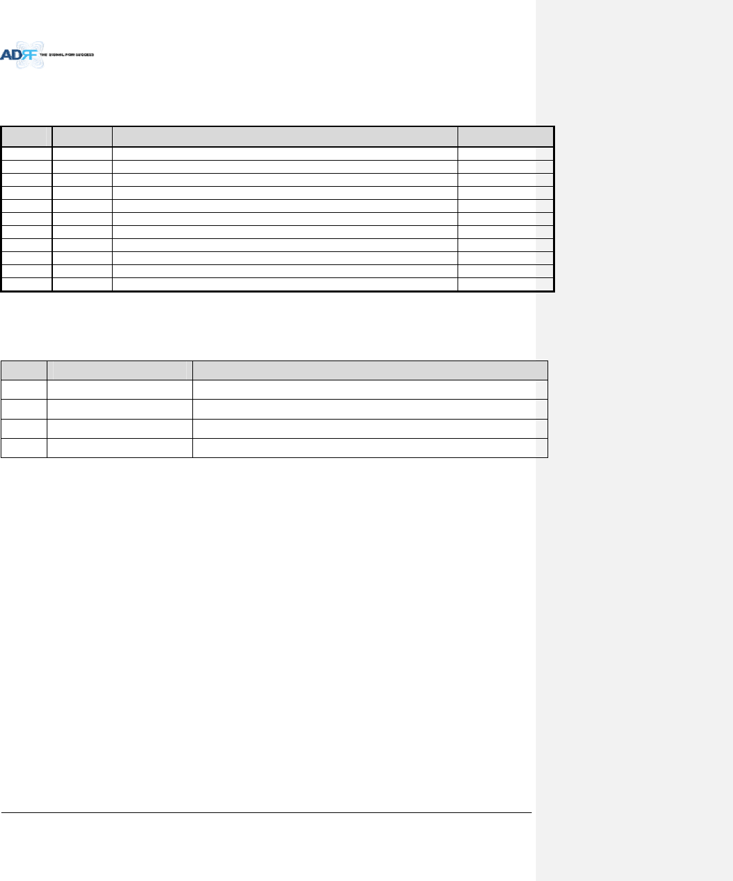
1.2 ADXDASQuickView
1.2.1 HEQuickView
1.2.2
19” rackmount
Holes
Host/RemoteSwitch,
HEview/RUviewSwitch
&RJ‐45port
OpticPorts
BatteryBackup
Port
RFUDuplexPort
ACInput&
On/OffSwitch
BCUInterfacePorts
BandCombinerUnit
(BCU)
OpticUnit(ODURACK)
ChannelCombiner
(CHC)
RFChannelUnit
(RFU)
PowerSupplyUnit
(PSU)
NMSUnit
BatteryBackup
On/OffSwitch
ACInputVoltage
SelectionSwitch
(110V/220V)
RFUSimplex
Port
OPT/ODUInterfacePorts
AUXCHInterface
Ports
RFPorts
connectedtoOPT
RFPorts
connectedtoCHC
BCUSumPort
Figure1‐1ADXDASHEQuickView
Groundterminal
AdvancedRFTechnologies,Inc. 16
DC IN +27VON/OFF
OUT
POWER
SOFT FAIL
HARD FAIL
IN
DC IN +27VON/OFF
OUT
POWER
SOFT FAIL
HARD FAIL
IN
DC IN +27VON/OFF
OUT
POWER
SOFT FAIL
HARD FAIL
IN
POWER
SOFT FAIL
HARD FAIL
COMM
OPTIC FAIL
DC IN +27V PSU ALARM RS-485GUI
OPTIC
ON/OFF
ON
1234
ADDR
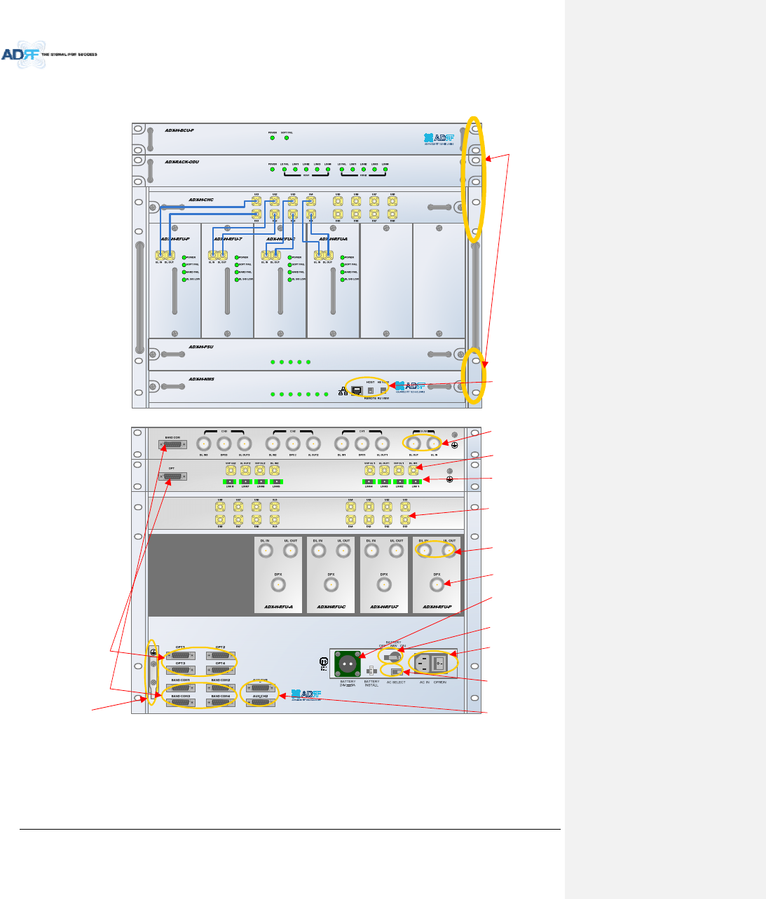
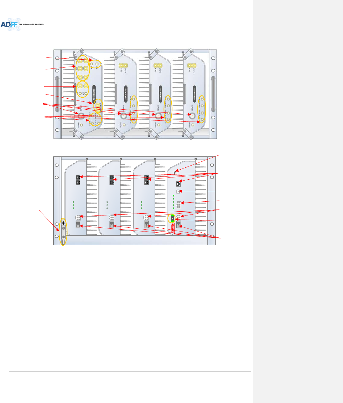
1.2.3 RUQuickView
Figure1‐2ADXDASRUQuickView
ServerAntennaPort
PortsforaddingExternal
Filter,ifneeded
PowerOn/OffSwitch
ExpansionRFportsto
supportadditional(4)
slaveRU.
MasterRUSlaveRU#1 SlaveRU#2 SlaveRU#3
DCInputPorts
OpticPort
PortforreceivingAlarm
StatusofRUPSU
GUIAccessPort
Communicationport
betweenMasterRUand
SlaveRU(RS‐485interface)
DipSwitchforMaster
AddressSettingmanually
Groundterminal
RFportsconnectedto
SlaveRUsinsame
chassis.
RFportsforMasterRU
connection.
RFportsforVHF/UHF
Expansion.
AdvancedRFTechnologies,Inc. 17
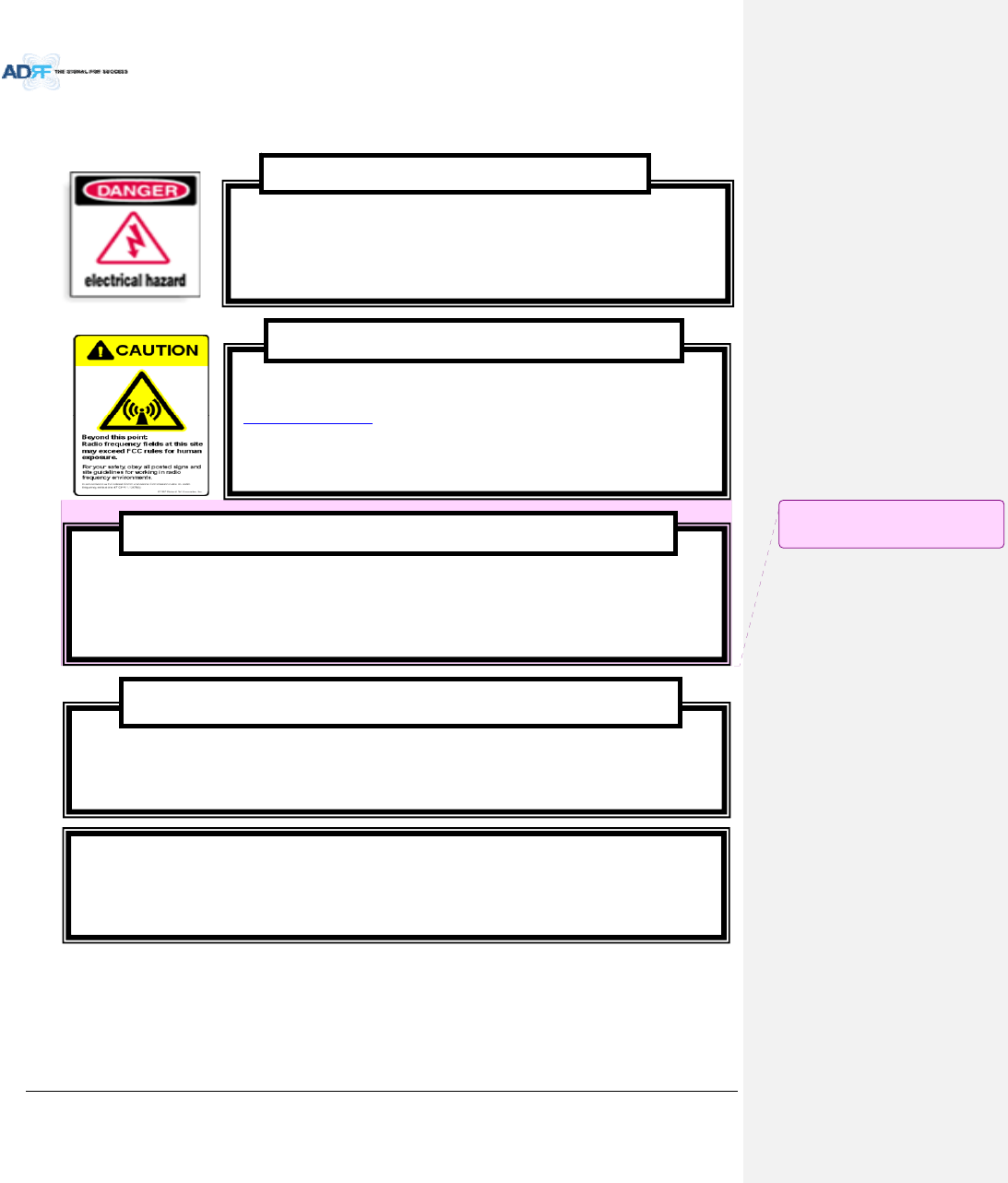
1.3 WarningsandHazards
LithiumBattery:CAUTION.RISKOFEXPLOSIONIFBATTERY ISREPLACEDBY INCORRECTTYPE.
DISPOSEOFUSEDBATTERIESACCORDINGTOINSTRUCTIONS.
OpeningortamperingtheADXDASwillvoidallwarranties.
WARRANTY
Actualseparationdistanceisdeterminedupongainofantennaused.
Pleasemaintainaminimumsafedistanceofatleast50cmwhileoperatingnearthedonorandtheserverantennas.
RFEXPOSURE&ANTENNAPLACEMENTGuidelines
WorkingwiththeADXDASwhileinoperation,mayexposethetechniciantoRF
electromagneticfieldsthatexceedFCCrulesforhumanexposure.VisittheFCCwebsiteat
www.fcc.gov/oet/rfsafetytolearnmoreabouttheeffectsofexposuretoRFelectromagnetic
fields.
WARNING!EXPOSURETORF
OpeningtheADXDAScouldresultinelectricshockandmaycause
severeinjury.
WARNING!ELECTRICSHOCK
메모 [H1]: Donorantenna설치에대한
문구삭제.(HK)
AdvancedRFTechnologies,Inc. 18
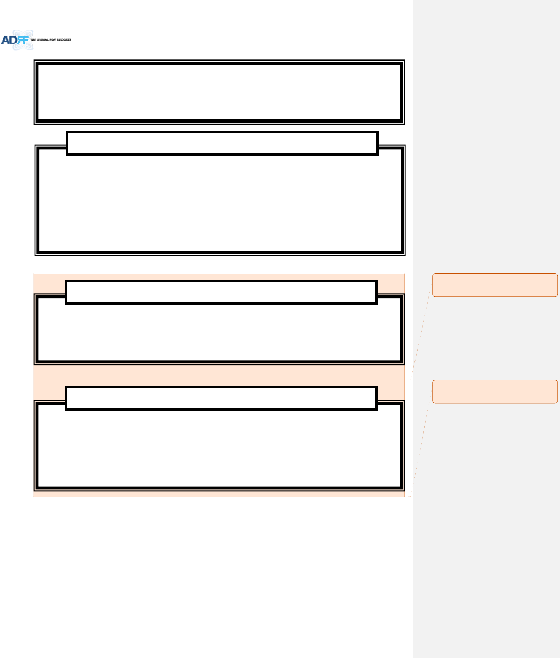
WANRNING.THISisNOTaCONSUMERdevice.ItisdesignedforinstallationbyFCCLICENSEESand
QUALIFIEDINSTALLERS.YouMUSThaveanFCCLICENSEorexpressconsentofanFCCLicenseeto
operatethisdevice.YouMUSTregisterClassBsignalboosters(asdefinedin47CFR90.219)
onlineat
www.fcc.gov/signal‐boosters/registration.Unauthorizedusemayresultinsignificantforfeiture
penalties,includingpenaltiesinexcessof$100,000foreachcontinuingviolation.
FCCPart90 ClassB
WANRNING.THISisNOTaCONSUMERdevice.ItisdesignedforinstallationbyFCCLICENSEESand
QUALIFIEDINSTALLERS.YouMUSThaveanFCCLICENSEorexpressconsentofanFCCLicenseeto
operatethisdevice.Unauthorizedusemayresultinsignificantforfeiturepenalties,including
penaltiesinexcessof$100,000foreachcontinuingviolation.
FCCPart20
NOTE:ThisequipmenthasbeentestedandfoundtocomplywiththelimitsforaClassA
digitaldevice,pursuanttopart15oftheFCCRules.Theselimitsaredesignedtoprovide
reasonableprotectionagainstharmfulinterferencewhentheequipmentisoperatedina
commercialenvironment.Thisequipmentgenerates,uses,andcanradiateradiofrequency
energyand,ifnotinstalledandusedinaccordancewiththeinstructionmanual,maycause
harmfulinterferencetoradiocommunications.Operationofthisequipmentinaresidentialarea
islikelytocauseharmfulinterferenceinwhichcasetheuserwillberequiredtocorrectthe
interferenceattheirownexpense.
FCCPart15ClassA
EthernetInstructions:Thisequipmentisforindooruseonly.Allcablingshouldbelimitedto
insidethebuilding.
메모 [Y2]: 추가
15/02/03
메모 [Y3]: 추가
15/02/03
AdvancedRFTechnologies,Inc. 19
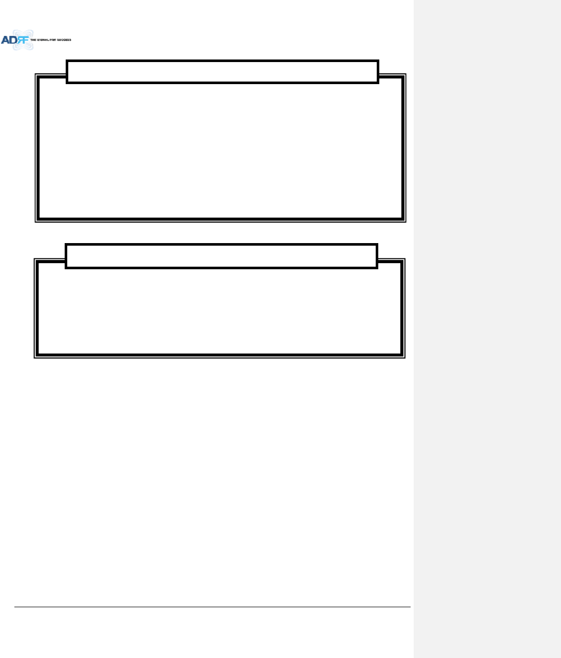
RSS‐GEN,Sec.7.1.2–(transmitters)
UnderIndustryCanadaregulations,thisradiotransmittermayonlyoperateusinganantennaofatypeand
maximum(orlesser)gainapprovedforthetransmitterbyIndustryCanada.Toreducepotentialradio
interferencetootherusers,theantennatypeanditsgainshouldbesochosenthattheequivalent
isotropicallyradiatedpower(e.i.r.p.)isnotmorethanthatnecessaryforsuccessfulcommunication.
Conformémentàlaréglementationd’IndustrieCanada,leprésentémetteurradiopeutfonctionneravec
uneantenned’untypeetd’ungainmaximal(ouinférieur)approuvépourl’émetteurparIndustrieCanada.
Danslebutderéduirelesrisquesdebrouillageradioélectriqueàl’intentiondesautresutilisateurs,
ilfautchoisirletyped’antenneetsongaindesortequelapuissanceisotroperayonnéequivalente(p.i.r.e.)
nedépassepasl’intensiténécessaireàl’établissementd’unecommunicationsatisfaisante.
RSS‐GEN,Sec.7.1.2–(detachableantennas)
Thisradiotransmitter(identifythedevicebycertificationnumber,ormodelnumberifCategoryII)hasbeen
approvedbyIndustryCanadatooperatewiththeantennatypeslistedbelowwiththemaximumpermissible
gainandrequiredantennaimpedanceforeachantennatypeindicated.Antennatypesnotincludedinthislist,
havingagaingreaterthanthemaximumgainindicatedforthattype,arestrictlyprohibitedforusewiththis
device.
Leprésentémetteurradio(identifierledispositifparsonnumérodecertificationousonnumérode
Donotremovetheprotectivecoversonthefiberopticconnectorsuntilaconnectionisreadytobe
made.Donotleaveconnectorsuncoveredwhennotconnected.
Thetipofthefiberopticconnectorsshouldnotcomeintocontactwithanyobjectordust.
Refertothecleaningprocedureforinformationonthecleaningofthefibertip.
CareofFiberOpticConnectors
FiberopticportsoftheADXDASemitinvisiblelaserradiationatthe1310,1550nmwavelength
window.
Toavoideyeinjuryneverlookdirectlyintotheopticalports,patchcordsoropticalcables.Do
notstareintobeamorviewdirectlywithopticalinstruments.Alwaysassumeopticaloutputison.
Onlytechniciansfamiliarwithfiberopticsafetypracticesandproceduresshouldperformoptical
fiberconnectionsanddisconnectionsoftheADXDASandtheassociatedcables.
TheADXDAScomplieswith21CFR1040.10and1040.11exceptfordeviationspursuanttolaser
noticeNo.50(July26.2001)@IEC60825‐1,Amendment2(Jan.2001).
LaserSafety

AdvancedRFTechnologies,Inc. 20
modèles’ilfaitpartiedumatérieldecatégorieI)aétéapprouvéparIndustrieCanadapourfonctionner
aveclestypesd’antenneénumérésci‐dessousetayantungainadmissiblemaximaletl’impédancerequise
pourchaquetyped’antenne.Lestypesd’antennenoninclusdanscetteliste,oudontlegainestsupérieur
augainmaximalindiqué,sontstrictementinterditspourl’exploitationdel’émetteur.
RFRadiationExposure
ThisequipmentcomplieswithRFradiationexposurelimitssetforthforanuncontrolledenvironment.
Thisequipmentshouldbeinstalledandoperatedwithaminimumdistanceof50cmbetweentheradiator
andyourbody.Thistransmittermustnotbeco‐locatedoroperatinginconjunctionwithanyotherantennaor
transmitter.RFexposurewillbeaddressedattimeofinstallationandtheuseofhighergainantennas
requirelargerseparationdistances.
RSS‐102RFExposure
L’antenne(oulesantennes)doitêtreinstalléedefaçonàmainteniràtoutinstantunedistance
minimumdeaumoins50cmentrelasourcederadiation(l’antenne)ettoutepersonnephysique.
Cetappareilnedoitpasêtreinstalléouutiliséenconjonctionavecuneautreantenneouémetteur.
AdvancedRFTechnologies,Inc. 21
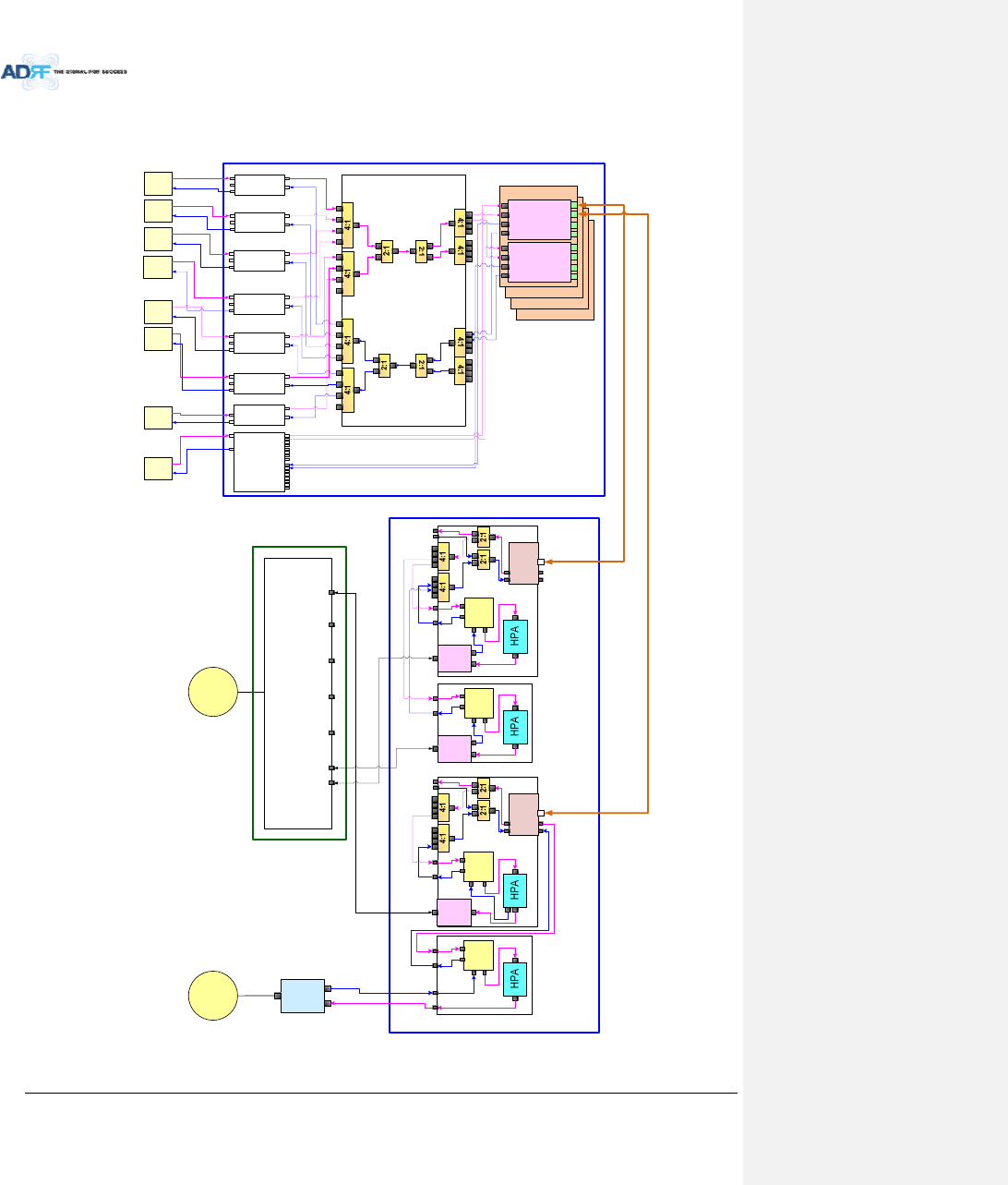
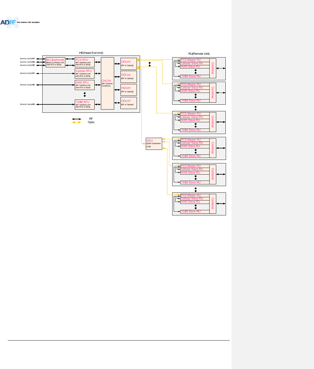
2. BLOCKDIAGRAM
2.1 ADXDASBlockDiagram
Figure2‐1ADXDASBlockDiagram
ODU
ODU
CCU
AWS BTS
PCS BTS
CELL
BTS
700M
BTS
Master RU
(P78)
Sub RU
(VU)
COM
PCS
CELL
AWS
700M
BT
WI-FI
ANT
Duplexer
RAU
AWS
RFU
TX
DPX
RX
DL
UL
700M
RFU
TX
DPX
RX
DL
UL
SMR
BTS
ODU
ODU
ODU#1
DL IN
V/UHF(136~512)
DL IN
(698~2690)
UL OUT
V/UHF(136~512)
UL OUT
(698~2690)
ODU#2
DL IN
V/UHF(136~512)
DL IN
(698~2690)
UL OUT
V/UHF(136~512)
UL OUT
(698~2690)
RAU
SMR
RFU
TX
DPX
RX
DL
UL
PS
RFU
TX
DPX
RX
DL
UL
PCS
RFU
TX
DPX
RX
DL
UL
CELL
RFU
TX
DPX
RX
DL
UL
Sub RU
(S89)
SMR
P78
BT BTS BT
RFU
DPX
RX
DL
UL
Duplexer
RAU
VU
RFU
TX
RX
DL
UL
PS
BTS
VHF/UHF
BTS
Master RU
(BT)
BPF
RAU
ANT VHF/UHF
Duplexer
HE
RU
ORU
ORU
AdvancedRFTechnologies,Inc. 22
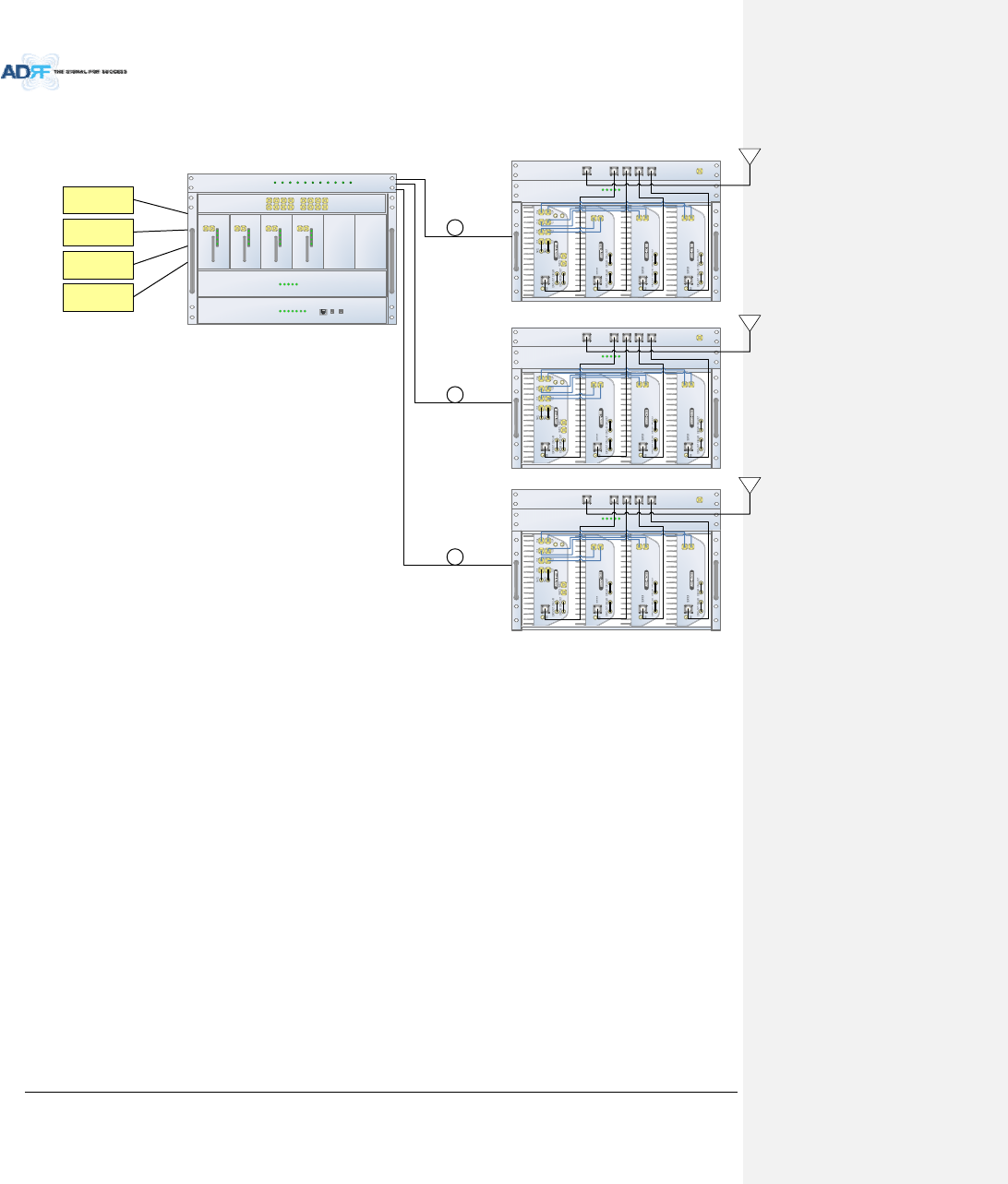
2.2 ADXDASTopology
Figure2‐2ADXDASTopology
AdvancedRFTechnologies,Inc. 23
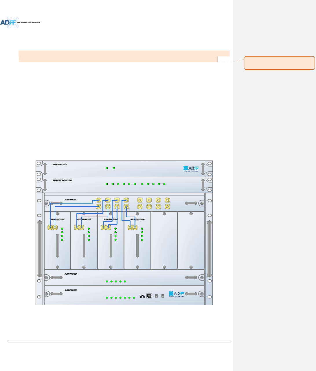
2.3 SISOConfiguration
Figure2‐3ADXDASSISOConfiguration
ADX-H-OPT
HE
ADX-H-PSU
POWER
CHG STS
ADX-H-CHC
DL 1 DL 2 DL 3 DL 4 DL 5 DL 6 DL 7 DL 8
UL 1 UL 2 UL 3 UL 4 UL 5 UL 6 UL 7 UL 8
POWER
ADX-H-RFU-P
UL_IN DL_OUT
SOFT FAIL
POWER
HARD FAIL
DL SIG LOW
ADS-H-RFU-7
UL_IN DL_OUT
SOFT FAIL
POWER
HARD FAIL
DL SIG LOW
ADX-H-RFU-C
UL_IN DL_OUT
SOFT FAIL
POWER
HARD FAIL
DL SIG LOW
ADX-H-RFU-A
UL_IN DL_OUT
SOFT FAIL
POWER
HARD FAIL
DL SIG LOW
LD FAIL 1-4 LI NK1 LINK2 LINK3 LINK4 LD FAIL 5-8 LINK5 LINK6 LINK7 LINK8
LOW BATT
AC FAIL
DC FAIL
ADX-H-NMS
HOST
REMOTE
POWER
SOFT-FAIL-H
HE VIEW
RU VIEW
SOFT-FAIL-R
HARD-FAIL-H
HARD-FAIL-R
LINK FAIL-H
LINK FAIL-R
700MHz
eNode-B
Cellular
BTS
PCS
BTS
AWS
BTS
RF
ADX-R-CHC
ADX-H-PSU
CELL700MPCS
COM WIFI
RU
E-DL E-UL
DL-IN UL-OUT DL-IN UL-OUT DL-IN UL-OUT
POWER
CHG STS
LOW BATT
AC FAIL
DC FAIL
Optic
Optic
Optic
AWS
ADX-R-CHC
ADX-H-PSU
CELL700MPCS
COM WIFI
RU
E-DL E-UL
DL-IN UL-OUT DL-IN UL-OUT DL-IN UL-OUT
POWER
CHG STS
LOW BATT
AC FAIL
DC FAIL
AWS
ADX-R-CHC
ADX-H-PSU
CELL700MPCS
COM WIFI
RU
E-DL E-UL
DL-IN UL-OUT DL-IN UL-OUT DL-IN UL-OUT
POWER
CHG STS
LOW BATT
AC FAIL
DC FAIL
AWS
AdvancedRFTechnologies,Inc. 24
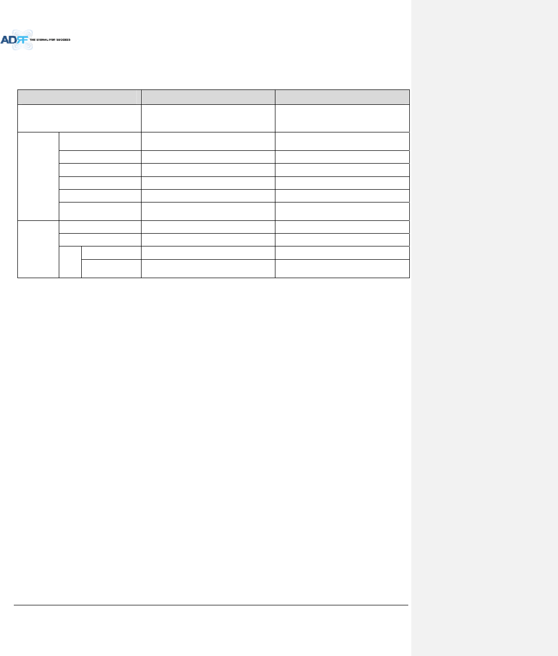
2.4 ADX‐DASScalability
Table2‐1ADX‐DASScalability
UnitScalabilityRemarks
Supportedband
700MHz,Cellular,AWS1W/2W,PCS
1W/2W,SMR800/900,PS700,VHF,UHF,
BRS
700MHzincludesLowerA,LowerB,
LowerC,andUpperC
HE
RFUUpto8upto6:cardtype
7th&8thRFU:19”racktype
NMS1
ChannelCombiner1
OpticUnitUpto4
BandCombinerUnitUpto4Tosupportmultiplecarriers
PowerSupplyUnit
(ACorDC)1Capableofsupplyingpowerto8RFUs,4
BCUs,4OPTsandNMS.
RU
RUUpto60
OEUUpto4
PSU
Adaptortype1perremotemodule
19”rackmount
(ACorDC)1Capableofsupplyingpowerto8Remote
Modules
AdvancedRFTechnologies,Inc. 25
3. ADXOVERVIEW
3.1 HeadEnd
TheheadendunitmustalwaysbeconnectedtotheBaseStationusingadirectcabledconnection.This
systemhasnotbeenapprovedforusewithawirelessconnectionviaserverantennatothebasestation.
Headendcomponentsinclude:
ADX‐H‐NMS(NetworkManagementSystem)
ADX‐H‐CHC(HeadEndChannelCombiner)
ADX‐H‐PSU(HeadEndPowerSupply)
Upto[4]ADX‐H‐BCU(BandCombinerUnit)
Upto[8]ADX‐H‐RFU‐x(RFUnit)
Upto[4]ADX‐H‐RACK‐ODU(OpticalUnitrack)eachADX‐H‐RACK‐ODUenablestohaveupto2
ODU(ADX‐H‐ODU‐4‐X)s
Specifications
‐ Size:19.0x14.6x12.2inches(482x370x311mm)
‐ Weight:83.7lbs(38.0Kg)@4RFU,CHC‐H,PSUandNMS
‐ PowerConsumption:52W@4RFU,2ODUsandNMS,28W@1RFU,2ODUsandNMS
‐ PowerInput:110VACor‐48VDC(optional)
‐ SupportstheADRF‐BBUforexternalbatterybackupsolution
POWER
SOFT FAIL-H
SOFT FAIL-R
HARD FAIL-H
HARD FAIL-R
LINK FAIL-H
LINK FAIL-R
HOST HE VIEW
REMOTE RU VIEW
POWER
CHG STS
LOW BATT
AC FAIL
DC FAIL
DL OUTUL IN
HARD FAIL
DL SIG LOW
SOFT FAIL
POWER
DL OUTUL IN
HARD FAIL
DL SIG LOW
SOFT FAIL
POWER
DL OUTUL IN
HARD FAIL
DL SIG LOW
SOFT FAIL
POWER
DL OUTUL IN
HARD FAIL
DL SIG LOW
SOFT FAIL
POWER
UL1 UL2 UL3 UL4
DL1 DL2 DL3 DL4
UL5 UL6 UL7 UL8
DL5 DL6 DL7 DL8
LD FAIL5-8 LINK5 LINK6 LINK7 LINK8LD FAIL1-4 LINK1 LINK2 LINK3 LINK4POWER
SOFT FAILPOWER
Figure3‐1HeadEndFrontView
메모 [Y4]: 추가
15/02/03
AdvancedRFTechnologies,Inc. 26
3.1.1 NMS(NetworkManagementSystem)
Functionsandfeatures
‐ SupportsSNMPv1,v2,andv3(get,set&trap)andweb‐basedGUIInterface.
‐ Monitorsalarmsandstatus
‐ Providescontrolinterfaceswithallsubordinatemodules
‐ ProvidesoverallDASstructureviatheautotreeupdatefunction
Spec
‐ Size:19.0x12.1x1.7inches
‐ Weight:5.5lbs
Figure3‐2ADX‐H‐NMSFrontView
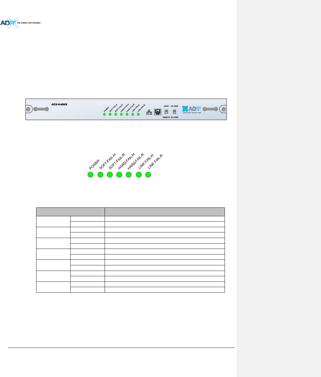
3.1.1.1 LEDs
NMShasLEDsonthefrontpanelasshowninFigure3‐3.
Figure3‐3NMSLED
Table3‐1NMSLEDSpecifications
ADXDAS‐NMSSpecifications
PowerSolidGreenNMSpowerisON
OFF NMSpower is OFF
SOFTFAIL‐HSolidYellowHESoftFailalarmexists inthesystem
SolidGreenNoHESoftFailalarms arepresentinthesystem
SOFTFAIL‐RSolidYellowRUSoftFailalarmexists inthesystem
SolidGreenNoRUSoftFailalarms arepresentinthesystem
HARDFAIL‐HSolidRedHEHard Failalarmexists inthesystem
SolidGreenNoHEHard Failalarms arepresentinthesystem
HARDFAIL‐RSolidRedRUHard Failalarmexists inthesystem
SolidGreenNoRUHard Failalarms arepresentinthesystem
LINKFAIL‐HSolidYellowHELinkFailalarmexists inthesystem
SolidGreenNoHELink Failalarms arepresentinthesystem
LINKFAIL‐RSolidYellowRULinkFailalarmexists inthesystem
SolidGreenNoRULink Failalarms arepresentinthesystem
AdvancedRFTechnologies,Inc. 27
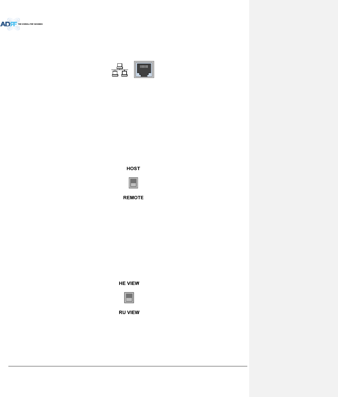
3.1.1.2 EthernetPort
TheEthernetportcanbeusedtocommunicatedirectlywiththeADXDASusingaRJ‐45crossovercableorcan
alsobeusedtoconnecttheADXDAStoanexternalmodembox.
Figure3‐4EthernetPort
3.1.1.3 Host/RemoteSwitch
TheHost/RemoteSwitchallowstheusertoswitchthedefaultRepeaterIP,SubnetMask,andGatewayofthe
repeatertoanalternativesetup.ThesesettingscanbeadjustedbyloggingintotheADXDASinHOSTmodeand
configuringthesettingsundertheModemBoxSettingsectionundertheInstallPageofNMS.
Oncethesettingsareset,flippingtheswitchtotheREMOTEpositionwillrebootNMSmodulewiththenew
alternatesettings.PleasenotethatwhentheNMSissettotheREMOTEposition,DHCPisdisabledandtheNMS
willnotautomaticallyassignanIPaddresstoanydevicethatconnectsdirectlytotheNMS.
Figure3‐5Host/RemoteSwitch
HostIP:192.168.63.1(FixedIP,unabletomodifythisIPaddress)
RemoteIP:192.168.63.5(DefaultIP,butcanbemodifiedinHostmode)
3.1.1.4 HEView/RUViewSwitch
TheHEView/RUViewSwitchallowstheusertodisabletheperiodicmonitoringperformedbytheNMS.Inthe
HEviewmode,theNMSmonitorsthestatusofallsubordinateunitsconnectedtoNMSbutwhenswitchedtoRU
viewtheNMSdoesnotmonitorthesubordinateunits.RUViewmodewillallowtheusertogotoaRUand
monitor/controltheHE.IftheNMSissettotheHEViewmodeandtriestoconnecttoaRUtomonitortheHE,
datacollisionsbetweentheNMSandRUmaypreventtheuserfromproperlymonitoringorconfiguringtheHE
whenattheRU.
Figure3‐6HEView/RUViewSwitch
AdvancedRFTechnologies,Inc. 28
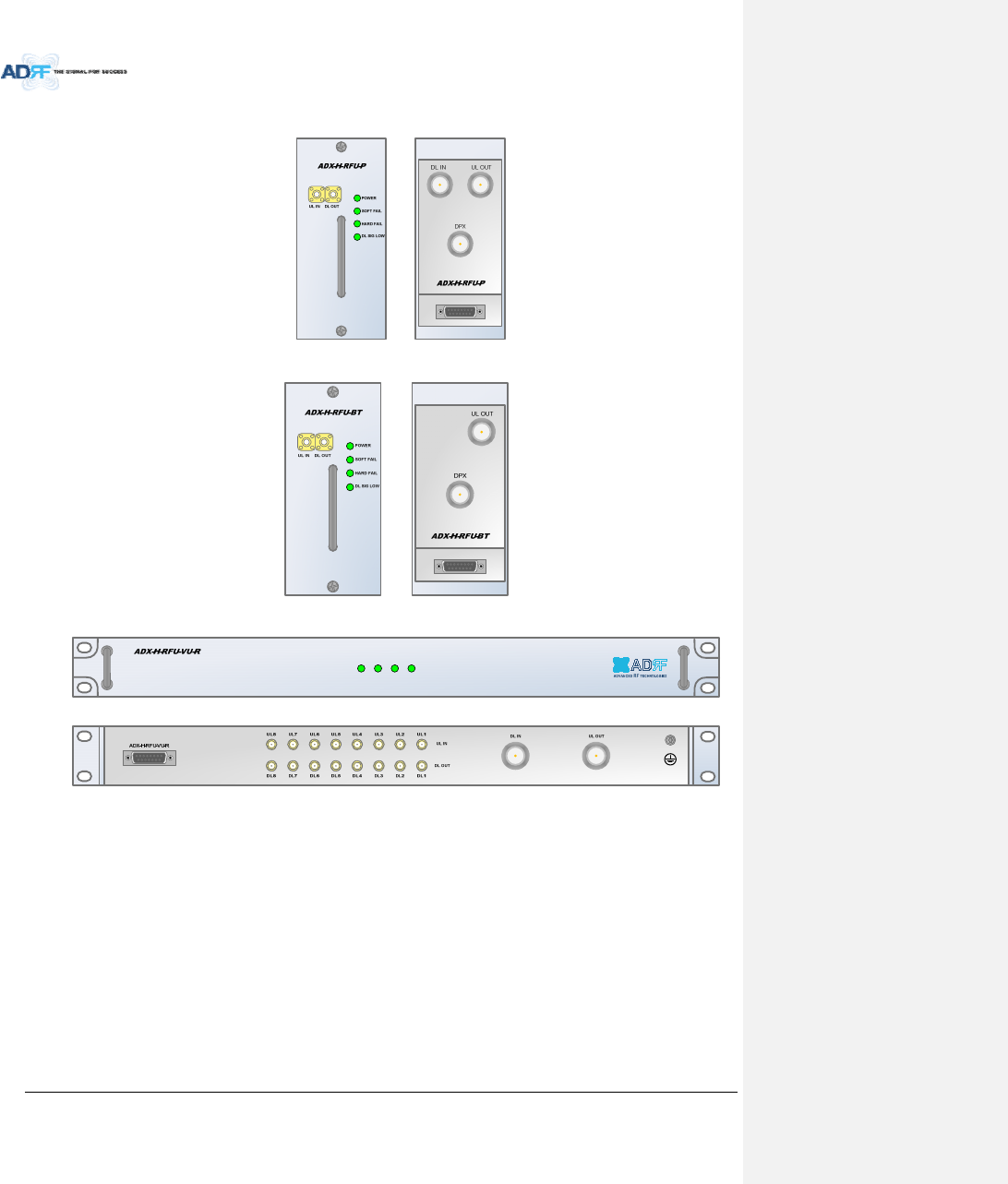
3.1.2 RFU(ADX‐H‐RFU‐x)
Figure3‐7RFUFront&RearView(excludingBTandVU)
Figure3‐8RFUFront&RearViewforBT
Figure3‐9RFUFront&RearViewforVU
Functionsandfeatures
‐ ProvideRFinterfacewithBTS
‐ EachRFUhasindependentgaincontrolandfiltering
‐ Modulartypeandhotswappable
‐ SupportsduplexportorsimplexTX&RXports
‐ EasilysupportadditionalfrequencybandsbyaddingasingleRFU
‐ Reducescomplexityandoverallequipmentsize
Specifications
‐ Size:12.8x6.2x2.8inches
‐ Weight:7.3lbs
POWER
SOFT FAIL
HARD FAIL
DL SIG LOW
AdvancedRFTechnologies,Inc. 29
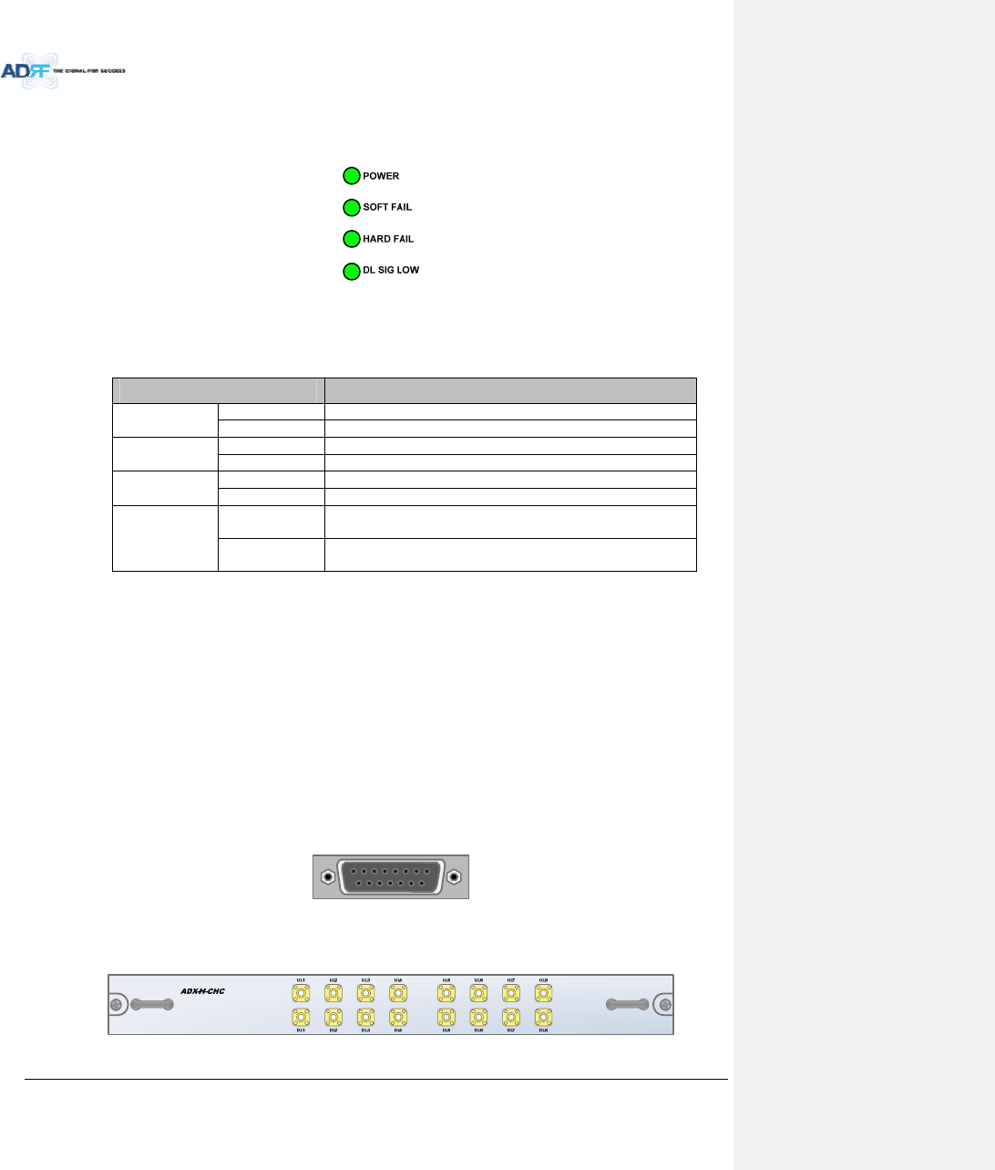
3.1.2.1 LEDs
RFUhasLEDsonthefrontpanelasshowninFigure3‐10.
Figure3‐10RFULED
Table3‐2RFULEDSpecifications
ADXDAS‐ModuleSpecifications
PowerSolidGreenModulepowerisON.
OFF Modulepower is OFF.
SoftFailSolidYellowSoftFailalarmexists intheRFU.
SolidGreenNoSoftFailalarms arepresent intheRFU.
HardFailSolidRedHardFailalarmexists intheRFU.
SolidGreenNoHardFailalarmsarepresentintheRFU.
DLSIGLOWSolidYellowWhenDLinputsignallevelislowerthanthedefinedthreshold
level.(defaultthresholdvalue:‐5dBm)
SolidGreenWhenDLinputsignallevelisupperthanthedefinedthreshold
level.
3.1.2.2 RFPorts
3.1.2.2.1 DLIN/ULOUT&DPXports
DLIN/ULOUT&DPXPorts(refertoFigure3‐7)arelocatedatthebackofRFUandcanbeconnecteddirectlyto
theBTS.TheRFUcansupportincomingsignalstrengthfrom0to25dBm(incaseofBTandVU,‐15~37dBm).
BTRFUdoesnothaveDLINportbecauseofTDD(Timedivisionduplex)system.
VURFUdoesnothaveDPXportbecausethereisexternallyoptionalDuplexercustomizedbyuserrequirement
forVHF/UHFsystem.
3.1.2.2.2 DLOUT/ULIN
DLOUT/ULINPorts(refertoFigure3‐7)arelocatedatthefrontoftheRFUandconnectdirectlytotheHE
ChannelCombiner(ADX‐H‐CHC).
3.1.2.3 CommunicationPort
TheADX‐H‐NMSmonitorsandcontrolstheRFUviathisport.DCPowerisalsoprovidedtotheRFUviathisport.
Figure3‐11CommunicationPort(RFU)
3.1.3 ChannelCombiner(ADX‐H‐CHC)
AdvancedRFTechnologies,Inc. 30
Figure3‐12ADX‐H‐CHCFront&RearView
Functions&Features
‐ CombinesDLsignalsreceivedfromeachRFUandfeedsthecombinedsignalstotheADX‐H‐OPT
‐ CombinesULsignalsreceivedfromeachRUandfeedsthecombinedsignaltotheADX‐H‐RFU
‐ Supportsupto8RFUsand(4)ADX‐H‐OPT‐8or(4)ADX‐H‐OPT‐4
‐ ChannelCombinerisnotconnectedtoVURFUbecauseVURFUinternallyincludes8waycombinerfor
connectionto8ODUs’VHFports
Specifications
‐ Size:16.9x12.9x1.7inches
‐ Weight:11.0lbs
3.1.3.1 RFports
3.1.3.1.1 RFportsatthefrontpanel(DL1toDL8,UL1toUL8)
DL1(toDL8)&UL1(toUL8)RFportsareconnectedtoDLOUT/ULINPortsatthefrontpanelofRFU.
ReceivethedownlinksignalfromeachRFU
SplittheuplinksignalreceivedfromODUtoeachRFU
3.1.3.1.2 RFportsatthebackpanel(DL1toDL8,UL1toUL8)
DL1(toDL8)&UL1(toUL8)RFportsareconnectedtoDLIN/ULOUTPortsatthebackpanelofOPT.
TransferthecombineddownlinksignalstoOPT
ReceivetheuplinksignalfromODU
3.1.3.2 RFports
3.1.3.2.1 RFportsatthefrontpanel(DL1toDL8,UL1toUL8)
DL1(toDL8)&UL1(toUL8)RFportsareconnectedtoDLOUT/ULINPortsatthefrontpanelofRFU.
ReceivethedownlinksignalfromeachRFU
SplittheuplinksignalreceivedfromODUtoeachRFU
3.1.3.2.2 RFportsatthebackpanel(DL1toDL8,UL1toUL8)
DL1(toDL8)&UL1(toUL8)RFportsareconnectedtoDLIN/ULOUTPortsatthebackpanelofOPT.
TransferthecombineddownlinksignalstoODU
ReceivetheuplinksignalfromODU
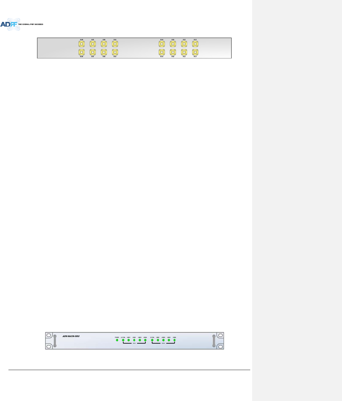
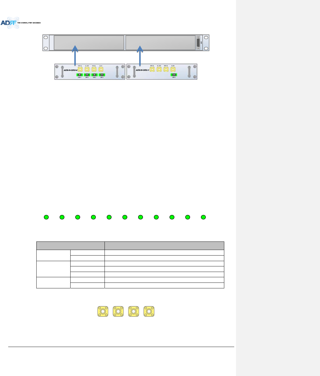
3.1.4 OpticDistributionUnit(ADX‐H‐ODU+ADX‐RACK‐ODU)
AdvancedRFTechnologies,Inc. 31
Figure3‐13ADX‐RACK‐ODU+ADX‐H‐ODU‐4/1Front&RearView
Functions&Features
‐ ConvertssignalfromRFtoopticandtransportssignalstoMasterRU
‐ ADX‐RACK‐ODUcansupportupto(2)ADX‐H‐ODUunits
‐ ADX‐H‐ODU‐4‐Xcansupportsupto(4)MasterRUswithupto5dBoloss(includingopticalconnectionloss)
‐ ADX‐H‐ODU‐1‐Xcansupports(1)MasterRUwithupto10dBoloss(includingopticalconnectionloss)
‐ Minimizesthenumberofopticfibercableneedbytransportingmultibandsignalsoverasinglestrandof
fiberusingWDMtechnology.
‐ VHFDLandVHFULportsforVHF/UHFbandtransmission
Spec
‐ ADX‐RACK‐ODU
o Size:19.0x12.9x1.7inches(482x327x44mm)
o Weight:4.2lbs
‐ ADX‐ODU‐1/4
o Size:7.96x7.17x1.64inches(202x182x41.5mm)
o Weight:3.2lbs
3.1.4.1 LEDs
TheADX‐H‐OPT‐8hasthefollowingLEDsonthefrontpanelasshowninFigure3‐14.TheADX‐H‐OPT‐4hasthe
sameLEDsexceptforLDFAIL5‐8,LINK5,LINK6,LINK7,ANDLINK8.
POWERLD F A I L 1- 4 LI N K 1 LI N K 2 LI N K 3 LI N K 4 LD F A I L 5- 8 LI N K 5 LI N K 6 LI N K7LI N K 8
Figure3‐14ADX‐H‐OPT‐8LED
Table3‐3ODURackLEDSpecifications
ADXDAS‐ModuleSpecifications
PowerSolidGreenModulepowerisON
OFF Modulepower is OFF
LDFAIL1‐4
/
LDFAIL5‐8
OFF ODUisnotinstalled
SolidYellowLDFailalarmexists intheODU
SolidGreenNoLDFailalarmis presentintheODU
LINK1toLINK8SolidYellowPDFailalarmexists
SolidGreenNoPDFailalarmis present
3.1.4.2 RFPorts
VHF UL 1 U L O U T 1VHF DL 1DL IN 1
Figure3‐15ODURFPorts
3.1.4.2.1 DLIN/ULOUT
AdvancedRFTechnologies,Inc. 32
ThecombineddownlinksignalreceivedfromADX‐H‐CHCistransferredtotheDLIN1(or2)atthebackofOPT.
TheULOUTportconnectsanyoftheportsonbackoftheADX‐H‐CHClabeledUL1~8.
3.1.4.2.2 VHFDL/VHFUL
VHFDL/UHFULportsareusedtosupportPublicSafetyintheVHF&UHFfrequencybands.VHF/UHFsignals
forPublicSafetybypasstheADX‐H‐CHCandconnectdirectlytotheVHFDL/UHFULportsoftheADX‐H‐OPT.
3.2 RemoteUnit
Theremoteunitiscomposedofa(1)MasterRUandupto(7)SlaveRU’s(ADX‐R‐4WSisrequiredwhen
connectingmorethan3SlaveRU’s).Apowersource,eithertheADX‐R‐ADP‐30(supports[1]Master/SlaveRU)or
theADX‐R‐PSU‐30(supportsupto[8]Master/SlaveRU)isrequired.
Specifications
‐ Size:19.0x12.9x10.5inches
‐ Weight:61.0lbs
‐ PowerInput:110VACor‐48VDC(optional)
Figure3‐16RUFrontView
Figure3‐17RURearView
POWER
SOFT FAIL
HARD FAIL
POWER
SOFT FAIL
HARD FAIL
POWER
SOFT FAIL
HARD FAIL
POWER
SOFT FAIL
HARD FAIL
COMM
OPTIC FAIL
AdvancedRFTechnologies,Inc. 33
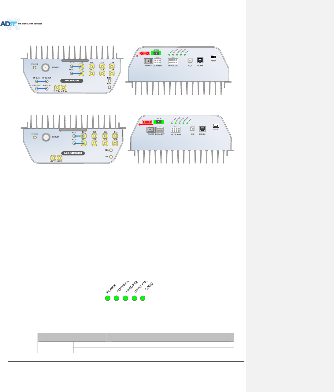
3.2.1 ADX‐R‐x3xM(MasterRU)
Figure3‐18MasterRUFront&RearView(excludingBT)
Figure3‐19MasterRUFront&RearViewonlyforBT
Functions&Features
‐ ConvertsDLopticsignaltoaRFsignal
‐ ConvertsULRFsignaltoanopticsignal
‐ SplitstheconvertedRFsignalsandwhichprovideRFtoSlaveRU’s
‐ TransmitsDLsignalandreceivesULsignalthroughserverantenna
‐ Supportsupto7slaveRUs
‐ Individuallywall‐mountableor19”rack‐mountable(requiresADX‐R‐CHA)
‐ SupportsexternalfiltersviaDLandULpass‐throughports
Specifications
‐ Size:11.8x9.8x4.5inches
‐ Weight:13.2lbs
3.2.1.1 LEDs
MasterRU’shavethefollowingLEDsonthefrontpanelasshowninFigure3‐20.
Figure3‐20MasterRULED
Table3‐4MasterRULEDSpecifications
ADXDAS‐ModuleSpecifications
PowerSolidGreenModulepowerisON
OFF Modulepower is OFF
AdvancedRFTechnologies,Inc. 34
SoftFailSolidYellowSoftFailalarmexists intheMasterRU
SolidGreenNoSoftFailalarms arepresent intheMasterRU
HardFailSolidRedHardFailalarmexists intheMasterRU
SolidGreenNoHardFailalarmsarepresentintheMasterRU
OpticFailSolidYellowOpticFailalarmexists intheMasterRU
SolidGreenNoOpticFailalarmispresentintheMasterRU
COMMSolidYellowCOMMFailalarmexists intheMasterRU
SolidGreenNoCOMM FailalarmispresentintheMasterRU
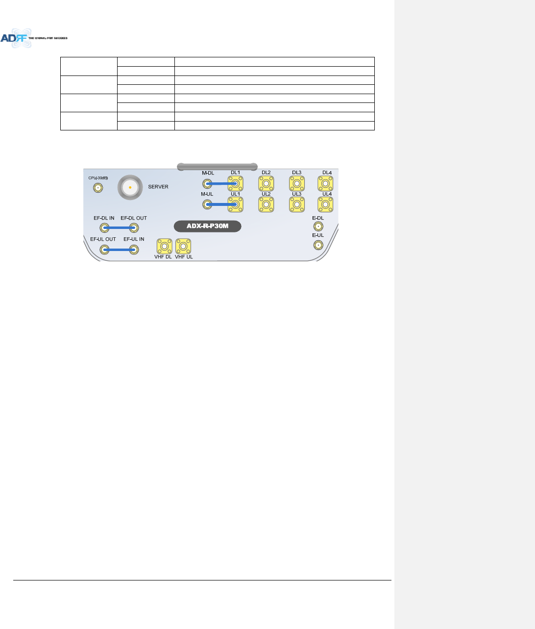
3.2.1.2 RFPorts
Figure3‐21RFPorts(MasterRU)
3.2.1.2.1 M‐DL/M‐UL,DL1toDL4&UL1toUL4
M‐DL/M‐ULports
‐ MasterRUunitswillcomewiththeM‐DLandM‐ULportspre‐connectedtotheDL1andUL1ports.
DL2toDL4&UL2toUL4ports
‐ SlaveRU’sconnecttotheDL2~DL4andUL2~UL4ports.
3.2.1.2.2 E‐DL/E‐UL
TheE‐DL/E‐ULportsconnecttotheADX‐R‐4WS(4‐waysplitter)
TheADX‐R‐4WSwillprovideanadditional(4)DLandULportstoconnectupto(4)additioanlSlaveRU’s
ADX‐R‐4WSdividestheoutputofE‐DLporttoextendedslaveRUsandcombines/transfersULsignalreceived
fromextendedslaveRUstoE‐ULport.
3.2.1.2.3 VHFDL/VHFUL
ConnectstotheADX‐R‐V25S(VHFSlaveRU)forpublicsafetyserviceintheVHF/UHFbands
3.2.1.2.4 SERVER&CPL
ServerPort
‐ ConnectsdirectlytoaserverantennaortheADX‐R‐CHC(remotechannelcombiner)
CPLPort
‐ 30dBcouplingportoffoftheserverport
3.2.1.2.5 EF‐DLIN/EF‐DLOUT&EF‐ULIN/EF‐ULOUT
ConnectstoanexternalDL/ULfilter
DLexternalfiltercanbeusedtoreduceDLout‐bandemissions
ULexternalfiltercanbeusedtoreduceout‐bandfrequenies
BTRUdoesnothaveexternalfilterportsbecausetherearenoissuesforexternalfiltering
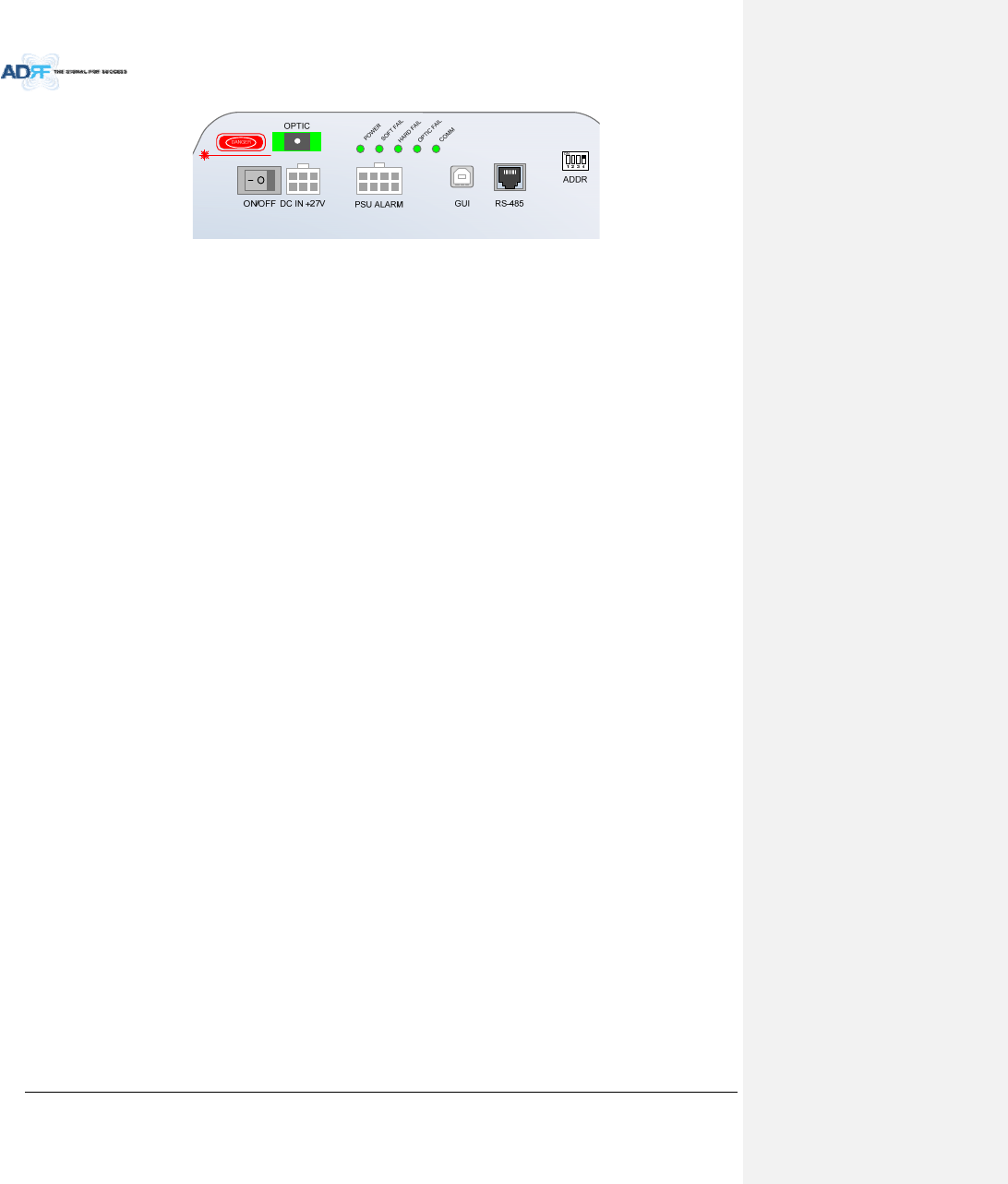
AdvancedRFTechnologies,Inc. 35
Figure3‐22Portsatthebackpanel(MasterRU)
3.2.1.3 OpticPort
ConnetstoADX‐H‐OPT‐8,ADX‐H‐OPT‐4,orADX‐R‐OEUviaopticline
3.2.1.4 PowerOn/OffSwitch&DCINPort
PowerOn/Offswitch
‐ MasterRUPowerOn/Offswitch
DCINPort
‐ ConnectstoDCoutputportofAC/DCadapter(ADX‐R‐ADP‐30)orRUPSU(ADX‐R‐PSU‐30)
3.2.1.5 PSUAlarmPort
ConnectstotheADX‐R‐PSU‐30
TheADX‐H‐NMSandtheMasterRUcanmonitorthestatusoftheADX‐H‐PSU‐30viathisport
3.2.1.6 GUIPort
ConnectstoalaptopviaUSBcable
Monitor/controltheRUandtheHEconnectedtotheRUusingUserGUI,whichisaWindowsbasedprogram.
ADRF32‐bitor64‐bitdriverswillalsoberequiredtoaccesstheRUusingtheUserGUI.
3.2.1.7 RS‐485Port
SlaveRUshouldbeconnectedtomasterRUinadiasychainstructureusingRS‐485linetomonitorandcontrol
slaveRUs.
TheRS‐485cableconnectedtomasterRUshouldbeconnectedtoRS‐485INportofslaveRU.Whenaslave
RUisconnectedtoanotherslaveRU,thentheRS‐485cableshouldbeconnectedfromtheRS‐485OUTportto
theRS‐485INofthe2ndSlaveRU.(Figure3‐23)
IfRS‐485portconnectionsbetweenRemoteModulesarenotcorrect,masterRUwillnotbeabletorecognize
allsubordinateslaveRUs.(Figure3‐24)
WARNING!TheRS‐485portsshouldNEVERbeconnectedtotheEthernetportoflaptoporEthernetNetwork
Equipment.DoingsomaycauseseriousdamagetotheRemoteModulesornetworkequipments.(Figure
3‐25)
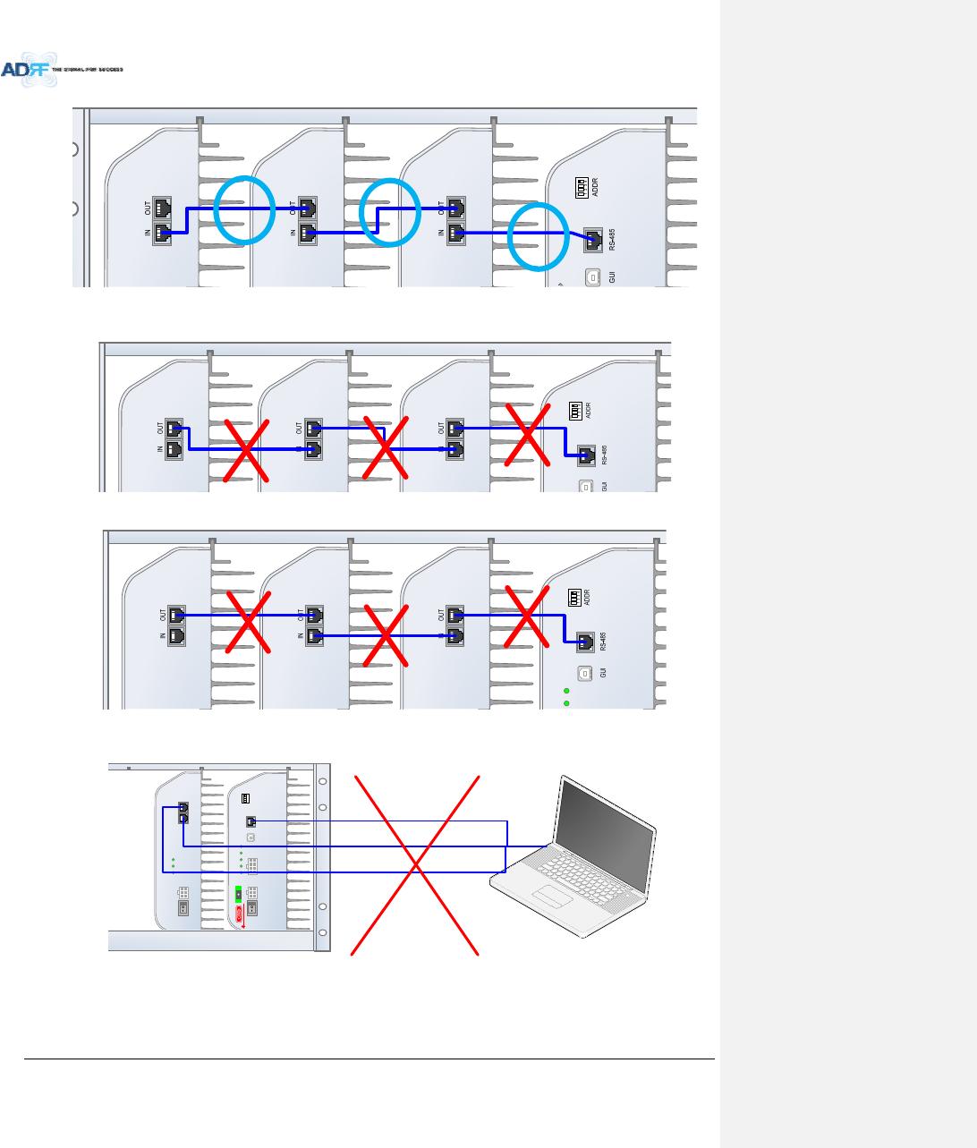
AdvancedRFTechnologies,Inc. 36
Figure3‐23CorrectRS‐485connectionbetweenMasterRUandSlaveRUorbetweenSlaveRUs
Figure3‐24WrongRS‐485connectionbetweenMasterRUandSlaveRUorbetweenSlaveRUs
Figure3‐25DoNOTconnectRS‐485portsofRemoteModuletonetworkequipmentport
3.2.1.8 ADDR
R
D
FAIL
R
D
FAIL
R
D
FAIL
R
D
FAIL
COMM
OPTIC FAIL
DC IN +27VON/OFF
OUT
POWER
SOFT FAIL
HARD FAIL
IN
POWER
SOFT FAIL
HARD FAIL
COMM
OPTIC FAI L
DC IN +27V PSU ALARM RS-485GUI
OPTIC
ON/OFF
ON
1234
ADDR
Laptop or Network Equipment
or
or
DAMAGE
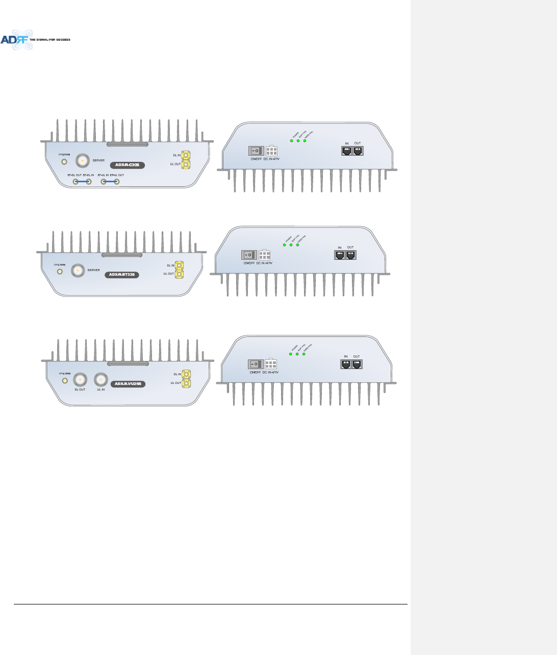
AdvancedRFTechnologies,Inc. 37
TheIDofmasterRUcanbesetmanuallyusingADDRswitch.Thisswitchshouldonlybeuseifinstructedby
ADRFTechnicalSupport.
3.2.2 ADX‐R‐xxxS/ADX‐R‐BTxxS/ADX‐R‐VU25S(SlaveRU)
Figure3‐26SlaveRUFront&RearView(excludingBTandVU)
Figure3‐27SlaveRUFront&RearView(BT)
Figure3‐28SlaveRUFront&RearView(excludingVU)
Functions&Features
‐ TransmitsDLsignalandreceivesULsignalthroughserverantennaport
‐ Individuallywall‐mountableor19”rack‐mountable(requiresADX‐R‐CHA)
‐ SupportsexternalfiltersviaDLandULpass‐throughports
Specification
‐ Size:11.8x9.8x3.7inches(300x249.6x94.5mm)
‐ Weight:11.7lbs(5.3kg)
3.2.2.1 LEDs
ADX‐R‐x30ShasthefollowingLEDsonthefrontoftheSlaveRUasshownbelowinFigure3‐29.
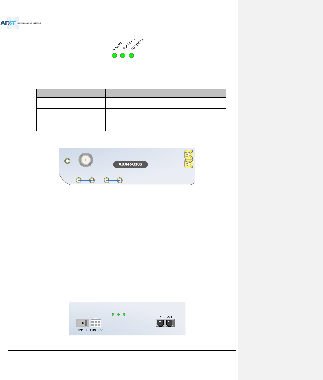
AdvancedRFTechnologies,Inc. 38
Figure3‐29SlaveRULED
Table3‐5SlaveRULEDSpecifications
ADXDAS‐ModuleSpecifications
PowerSolidGreenModulepowerisON
OFF Modulepower is OFF
SoftFailSolidYellowSoftFailalarmexists intheSlaveRU
SolidGreenNoSoftFailalarms arepresent intheSlaveRU
HardFailSolidRedHardFailalarmexists intheSlaveRU
SolidGreenNoHardFailalarmsarepresentintheSlaveRU
3.2.2.2 RFPorts
Figure3‐30RFPorts(SlaveRU)
3.2.2.2.1 DLIN&ULOUT
ConnectstooneoftheavaialbleDL2to4/UL2to4portsoftheMasterRU
DLINportreceivesthedividedDLoutputfromtheMasterRU
ULOUTporttransferstheULoutputofslaveRUtotheMasterRU
3.2.2.2.2 SERVER&CPL
ServerPort
‐ ConnectsdirectlytoaserverantennaortheADX‐R‐CHC(remotechannelcombiner)
CPLPort
‐ 30dBcouplingportoffoftheserverport
3.2.2.2.3 EF‐DLIN/EF‐DLOUT&EF‐ULIN/EF‐ULOUT
ConnecttoanexternalDL/ULfilter
DLexternalfiltercanbeusedtoreduceout‐bandemissions
ULexternalfiltercanbeusedtoreduceuplinkout‐bandsignals
BTandVURUdonothaveexternalfilterportsbecausetherearenoissuesforexternalfiltering
Figure3‐31Portsattherearpanel(SlaveRU)
DL IN
SERVER
CPL(-30dB)
UL OUT
EF-DL OUT EF-DL IN EF-UL IN EF-UL OUT
POWER
SOFT FAIL
HARD FAIL
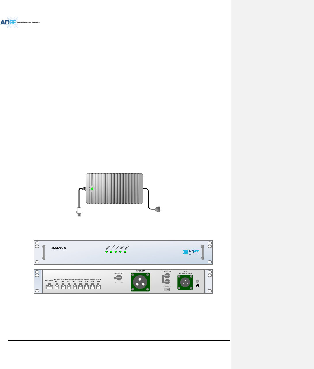
AdvancedRFTechnologies,Inc. 39
3.2.2.3 PowerOn/OffSwitch&DCINPort
PowerOn/Offswitch
‐ SlaveRUPowerOn/Offswitch
DCINPort
‐ ConnectedtoDCoutputportofAC/DCadaptor(ADX‐R‐ADP‐30)orRUPSU(ADX‐R‐PSU‐30)
3.2.2.4 RS‐485Port
SlaveRUshouldbeconnectedtomasterRUinadiasychainstructureusingRS‐485linetomonitorandcontrol
slaveRUs.
TheRS‐485cableconnectedtomasterRUshouldbeconnectedtoRS‐485INportofslaveRU.Whenaslave
RUisconnectedtoanotherslaveRU,thentheRS‐485cableshouldbeconnectedfromtheRS‐485OUTportto
theRS‐485INofthe2ndSlaveRU.(Figure3‐23)
IfRS‐485portconnectionsbetweenRemoteModulesarenotcorrect,masterRUwillnotbeabletorecognize
allsubordinateslaveRUs.(Figure3‐24)
WARNING!TheRS‐485portsshouldNEVERbeconnectedtotheEnthernetportoflaptoporEthernet
NetworkEquipment.DoingsomaycauseseriousdamagetotheRemoteModulesornetworkequipments.
(Figure3‐25)
3.2.3 RUPowerSupplyOptions
3.2.3.1 ADX‐R‐ADP(RUPowerAdapter)
TheADX‐R‐ADP‐30iscapableofpowering1remotemodule(MasterorSlaveRU).
3.2.3.2 ADX‐R‐PSU(RUPowerSupplyUnit)
Figure3‐32RUPSUFront&RearView
Functions&Features
‐ Providespowerto8remotemodules(MasterorSlaveRU)
‐ SupportsADRF‐BBUBatteryBackup
Spec
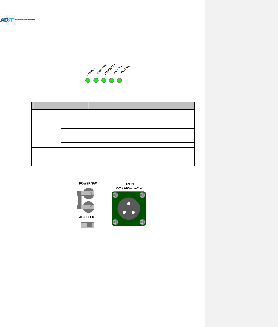
AdvancedRFTechnologies,Inc. 40
‐ Size:19.0x12.0x2.6inches(482x304x66mm)
‐ Weight:9.9lbs(4.5kg)
‐ PowerInput:110Vor220VAC,selectablebyswitch
3.2.3.2.1 LEDs
ADXDAShasthefollowingLEDsonthefrontoftheRUPSUasshownbelowinFigure3‐33.
Figure3‐33RUPSULED
Table3‐6RUPSULEDSpecifications
ADXDAS‐ModuleSpecifications
PowerSolidGreenModulepowerisON
OFF Modulepower is OFF
CHGSTSSolidYellowNoACpowerdetectedandADRF‐BBUisbeingused
BlinkingGreenADRF‐BBUisbeingcharged
SolidGreenCompletelyCharged
OFF Batteryis notconnected
LOWBATTSolidYellowLowBattery alarmexistinthePSU
SolidGreenNoLowBatteryalarmispresentinthePSU
ACFAILSolidYellowACFailalarmexistinthePSU
SolidGreenNoACFailalarmis present inthePSU
DCFAI
L
SolidYellowDCFailalarmexistintheRFU
SolidGreenNoDCFailalarms is present inthePSU
3.2.3.2.2 ACInputOn/OffSwitch,ACInputPortandACInputSelectionSwitch
Figure3‐34RUPSUPowerSwitchView
TheACPoweron/offswitchislocatedattherearoftheADX‐R‐PSU‐30.TheADX‐R‐PSU‐30canbeoperatedat
the110VACor220VAC.TheACInputVoltageshouldbeproperlysetbytheuser.
3.2.3.2.3 BatteryBackupPortandBatteryBackupSwitch
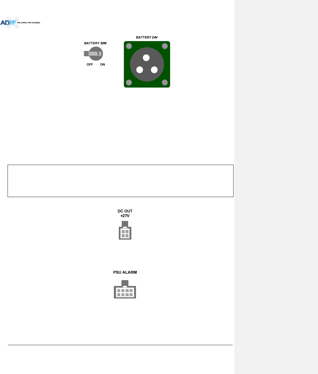
AdvancedRFTechnologies,Inc. 41
Figure3‐35BatteryBackupPort&BatteryBackupSwitch
WhentheBatteryS/WissettotheONposition,thepowersupplychargestheoptionalADRF‐BBU(External
BackupBattery)(Figure3‐35).
TheRUPSUcanbeconnectedtoanADRF‐BBU(ADRFBatteryBackupUnit)toprovidepowerduringapower
failure.IfanADRF‐BBUisutilized,connecttheADRF‐BBUtotheRUPSUviatheexternalbatterybackupportas
showninFigure3‐35.
(WARNING:ThecircuitswitchontheADRF‐BBUmustbesettoOFFbeforeconnectingtheADRF‐BBUtothe
HEPSUtopreventdamagetotheHEPSUortheADRF‐BBUandpersonalinjury.)
Note:PleasecontactADRFTechnicalSupportforassistanceifyouareunfamiliarwiththeinstallation
procedureofourbatterybox.
TheprocedureforconnectingRUPSUtoBBU
BATTS/WOFF
ConnectBBUtoRUPSUBatteryportusingRUbatterycable
BATTS/WON
3.2.3.2.4 DCOutputPort
Figure3‐36DCOutputPort(RUPSU)
(8)DCoutputportsareavailabletoconnectupto8remotemodules(MasterorSalveRU’s)
3.2.3.2.5 PSUAlarmPort
Figure3‐37PSUAlarmPort(RUPSU)
ConnectstotheMasterRUtomonitorthestatusoftheADX‐R‐PSU‐30
TheADX‐H‐NMS&MasterRUmonitorthestatusoftheADX‐R‐PSU‐30viathisport
4. CABLECONNECTION
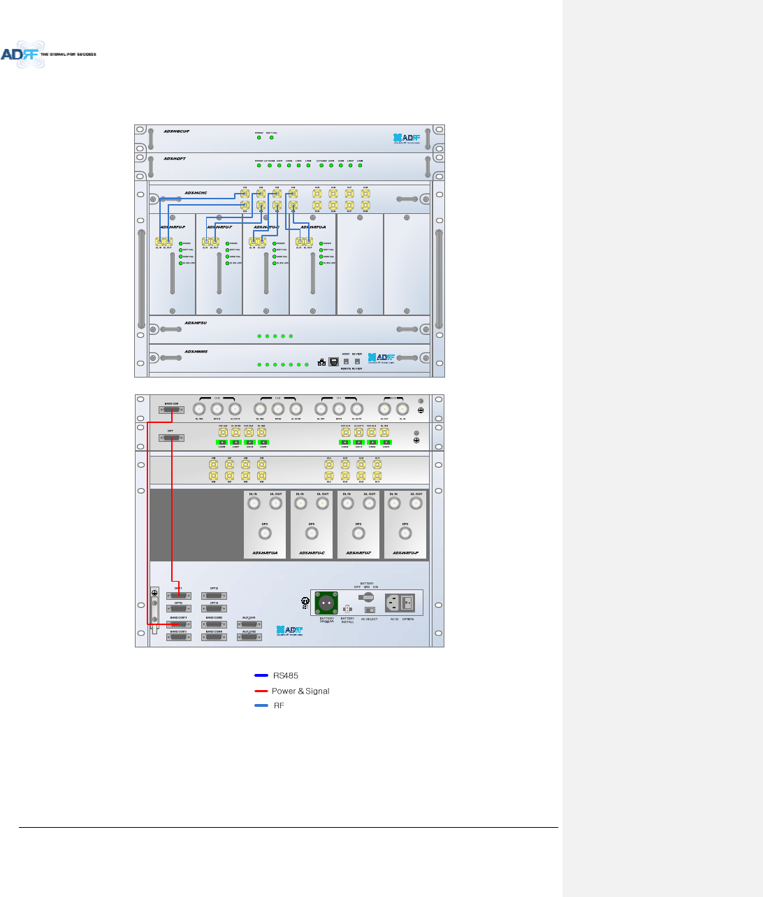
AdvancedRFTechnologies,Inc. 42
4.1 HeadEndConnectionDiagrams
4.1.1 Front/RearHeadEndConnectionViewwithOptionalBCUunit
POWER
SOFT FAIL-H
SOFT FAIL-R
HARD FAIL-H
HARD FAIL-R
LINK FAIL-H
LINK FAIL-R
POWER
CHG STS
LOW BATT
AC FAIL
DC FAIL
Figure4‐1HECableconnection(1OPT‐8+1BCU)
OFF
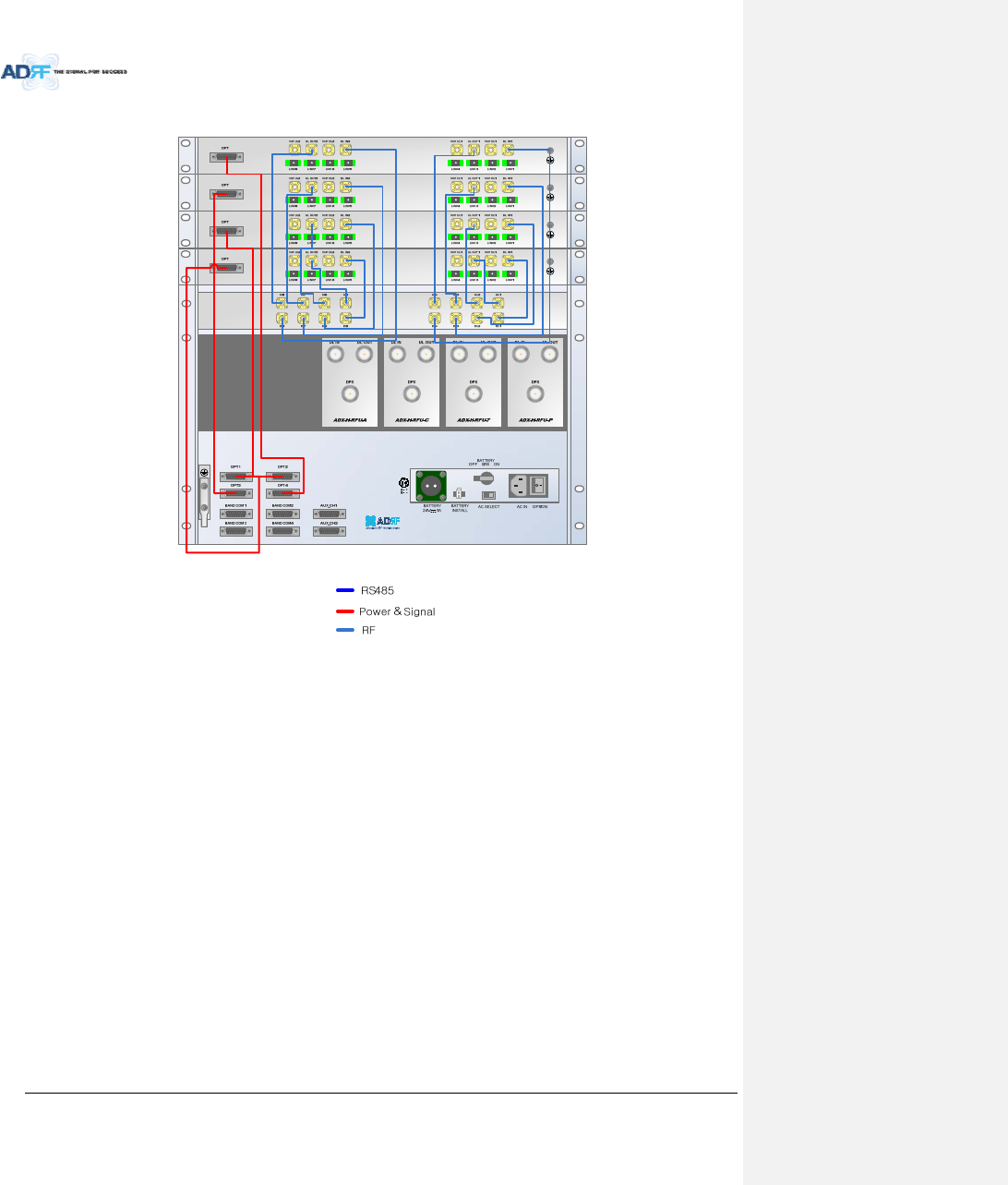
AdvancedRFTechnologies,Inc. 43
4.1.2 RearHeadEndConnectionViewwith(4)OPT‐8units
Figure4‐2HECableconnection(4OPTs)
OFF
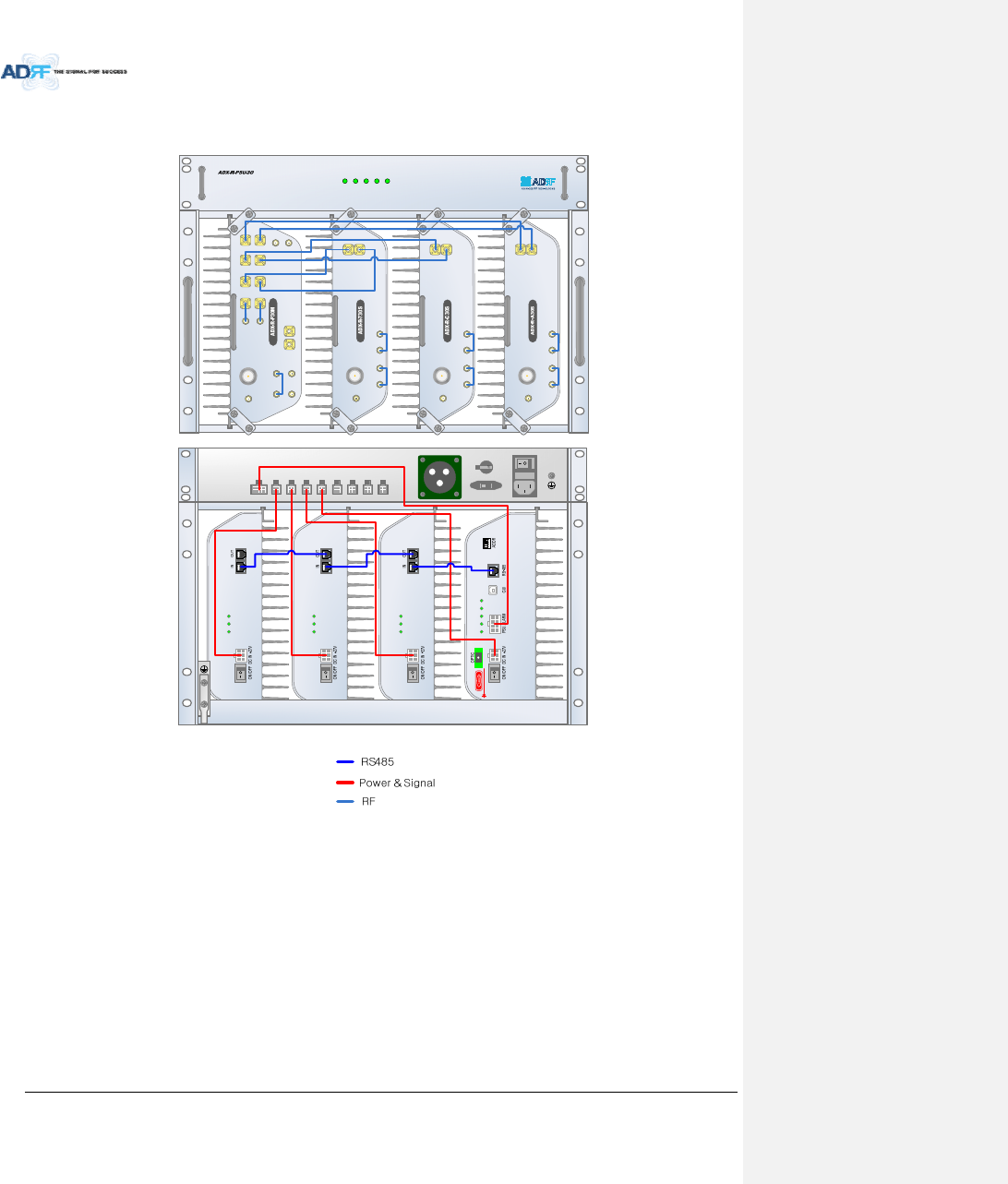
AdvancedRFTechnologies,Inc. 44
4.2 RemoteUnitConnectionDiagrams
Figure4‐3RUCableconnection(4RemoteModule+RUPSU)
POWER
CHG-STS
LOW BATT
AC FAIL
DC FAIL
DL IN
SERVER
CPL(-30dB)
UL OUT
EF-DL OUT EF-DL IN EF-UL IN EF-UL OUT
DL IN
SERVER
CPL(-30dB)
UL OUT
EF-DL OUT EF-DL IN EF-UL IN EF-UL OUT
DL IN
SERVER
CPL(-30dB)
UL OUT
EF-DL OUT EF-DL IN EF-UL IN EF-UL OUT
SERVER
UL1 UL2 UL3 UL4
DL1 DL2 DL3 DL4
M-DL
M-UL
CPL(-30dB)
E-DL
E-UL
VHF DL VHF UL
EF-DL IN EF-DL OUT
EF-UL INEF-UL OUT
AC IN
ON / OFF
AC SELECT
BATTERY S/W
BATTERY 24V
PSU ALARM DC OUT
+27V DC OU T
+27V DC OUT
+27V DC OUT
+27V DC OUT
+27V DC OUT
+27V DC OUT
+27V DC OUT
+27V
POWER
SOFT FAIL
HARD FAIL
POWER
SOFT FAIL
HARD FAIL
POWER
SOFT FAIL
HARD FAIL
POWER
SOFT FAIL
HARD FAIL
COMM
OPTIC FAIL
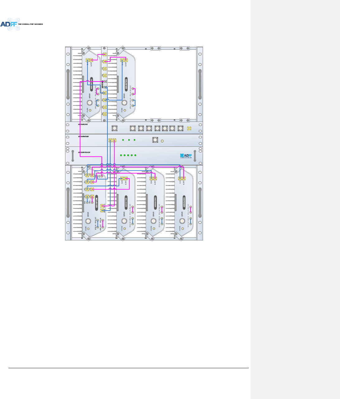
AdvancedRFTechnologies,Inc. 45
4.3 RemoteUnitw/4‐WayCombiner(ADX‐R‐4WS)
Figure4‐4SlaveRUExpansionusingADX‐R‐4WS
POWER
CHG-STS
LOW BATT
AC FAIL
DC FAIL
WiMAXCellularSMR800AWS700MPCS
COM WIFI
SMR900
POWER SOFT FAIL HARD FAIL
DL-IN UL-OUT MON
SERVER