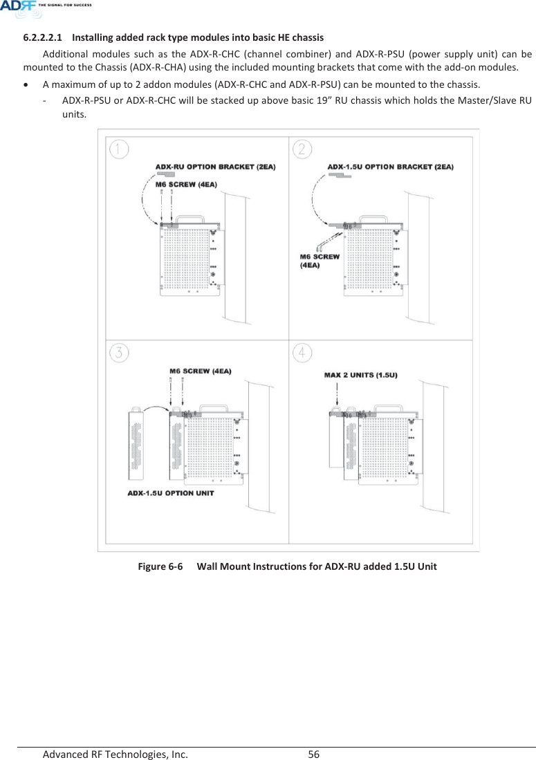
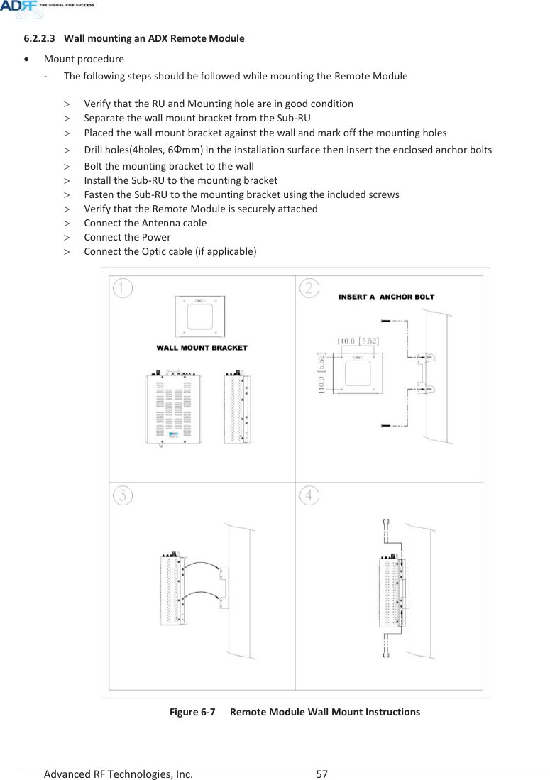
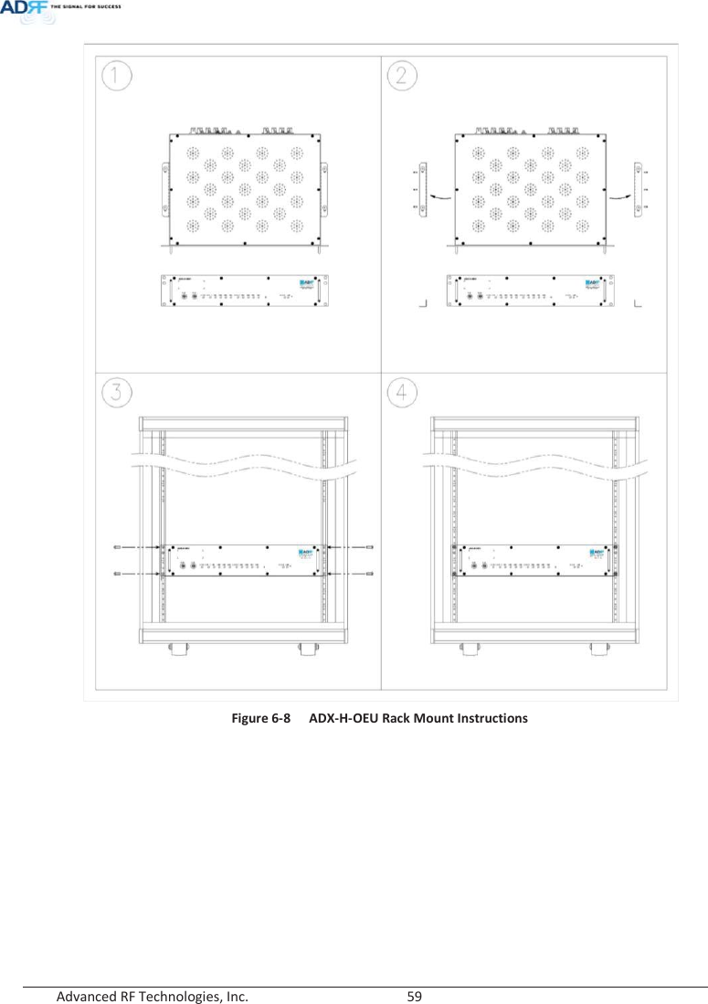
ADRF KOREA ADX-R-BT DAS (Distributed Antenna System) User Manual ADX DAS
ADRF KOREA, Inc. DAS (Distributed Antenna System) ADX DAS
UserManual.wiki
>
ADRF KOREA
>
ADX R BT User Manual
Users Manual
Navigation menu
Upload a User Manual
Namespaces
Wiki Guide
HTML
PDF
Info
Views
User Manual
Discussion / Help
Navigation
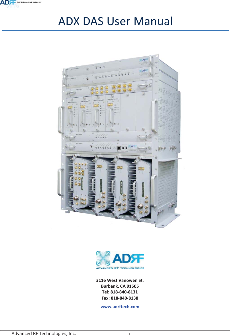
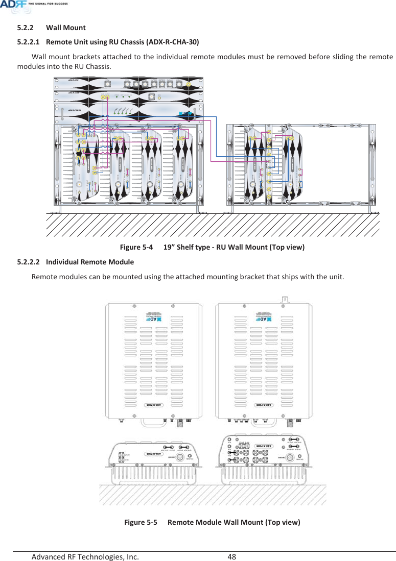
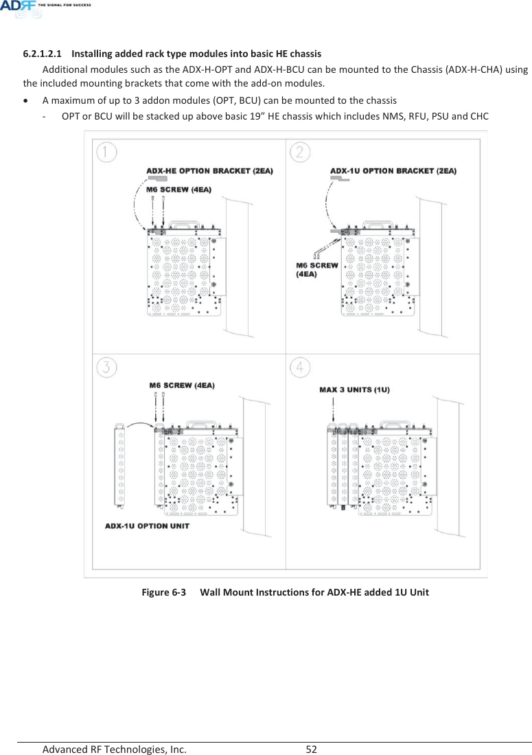
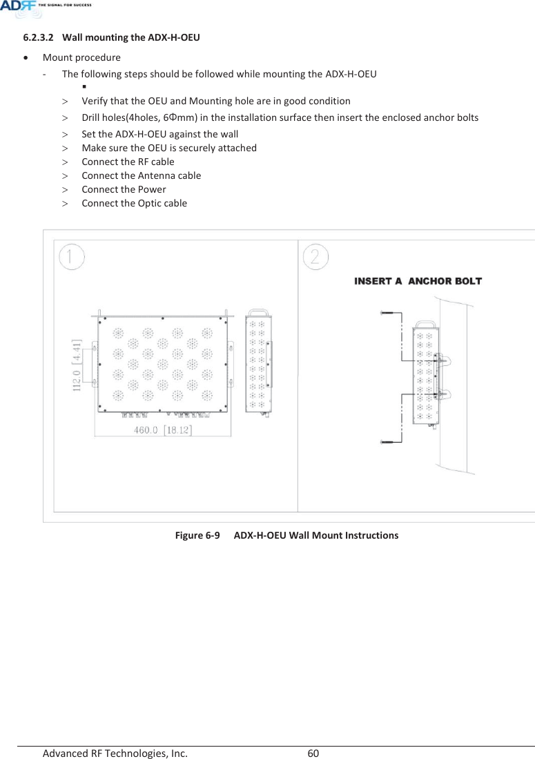
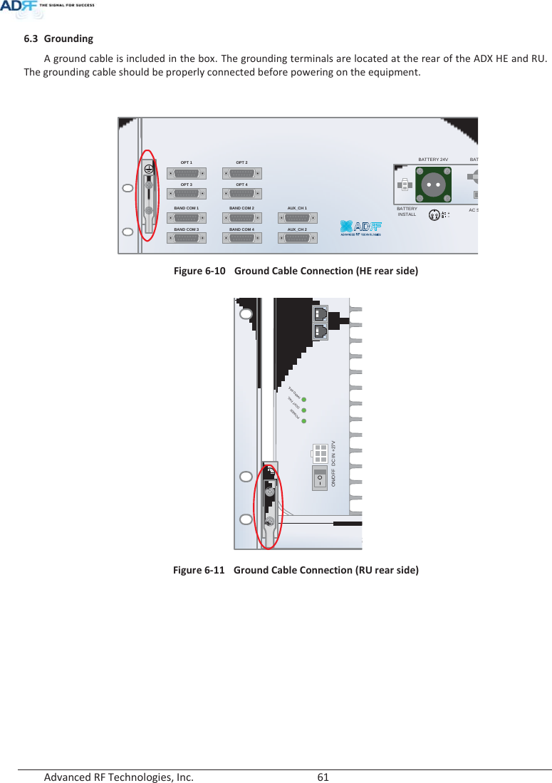
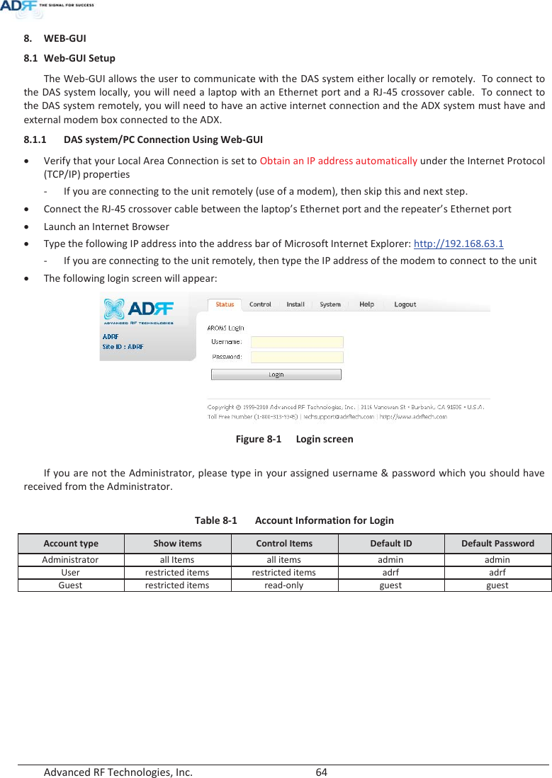
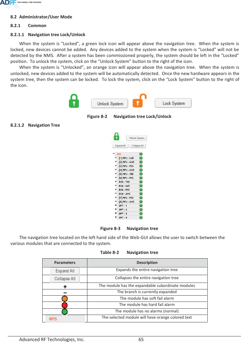
![Advanced RF Technologies, Inc. 18 WANRNING. THIS is NOT a CONSUMER device. It is designed for installation by FCC LICENSEES and QUALIFIED INSTALLERS. You MUST have an FCC LICENSE or express consent of an FCC Licensee to operate this device. You MUST register ClassS B signal boosters (as defined in 47 CFR 90.219) online at www.fcc.gov/signal-boosters/registeration. Unauthorized use may result in significant forfeiture penalties, including penalties in excess of $100,000 for each continuing violation. FCC Part 90 Class B WANRNING. THIS is NOT a CONSUMER device. It is designed for installation by FCC LICENSEES and QUALIFIED INSTALLERS. You MUST have an FCC LICENSE or express consent of an FCC Licensee to operate this device. Unauthorized use may result in significant forfeiture penalties, including penalties in excess of $100,000 for each continuing violation. FCC Part 20 NOTE: This equipment has been tested and found to comply with the limits for a Class A digital device, pursuant to part 15 of the FCC Rules. These limits are designed to provide reasonable protection against harmful interference when the equipment is operated in a commercial environment. This equipment generates, uses, and can radiate radio frequency energy and, if not installed and used in accordance with the instruction manual, may cause harmful interference to radio communications. Operation of this equipment in a residential area is likely to cause harmful interference in which case the user will be required to correct the interference at their own expense. FCC Part 15 Class A Ethernet Instructions: This equipment is for indoor use only. All cabling should be limited to inside the building. ָ֦ [Y1]: ɼ15/02/03 ָ֦ [Y2]: ɼ15/02/03](https://usermanual.wiki/ADRF-KOREA/ADX-R-BT/User-Guide-2525468-Page-18.png)
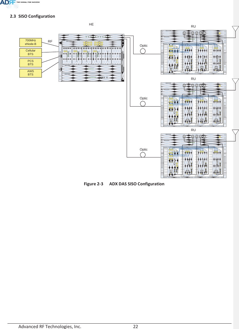
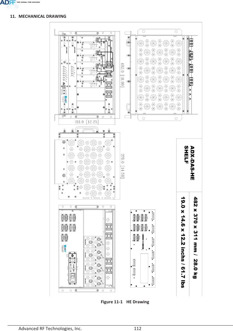
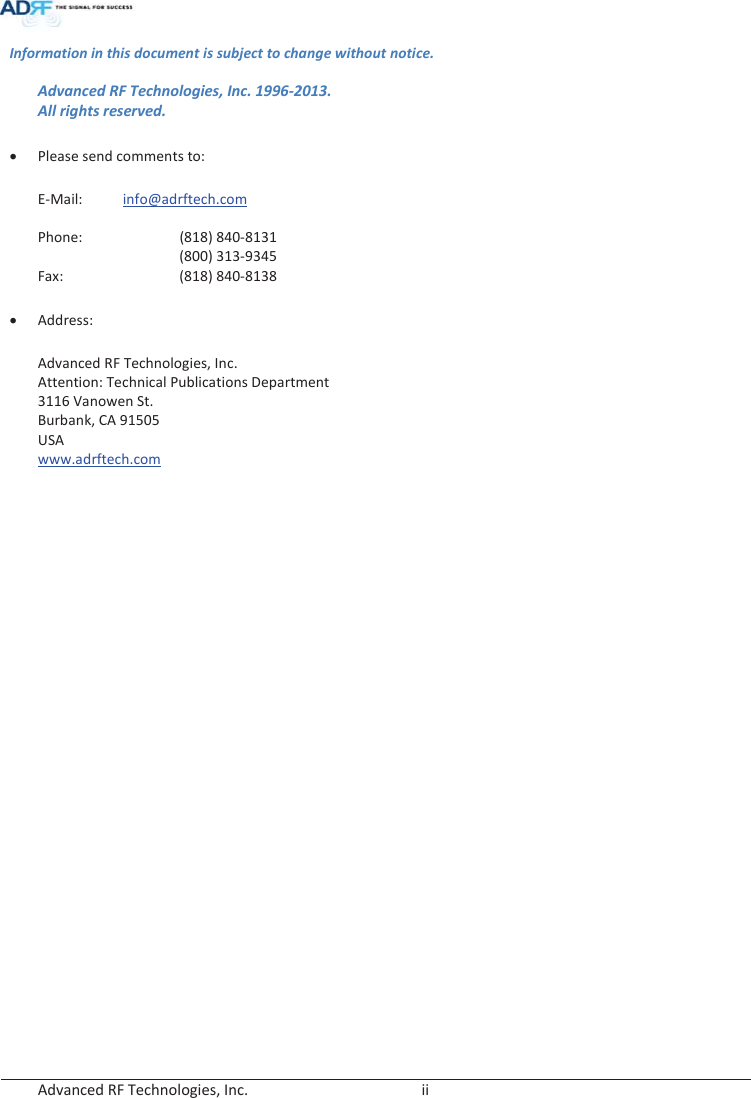
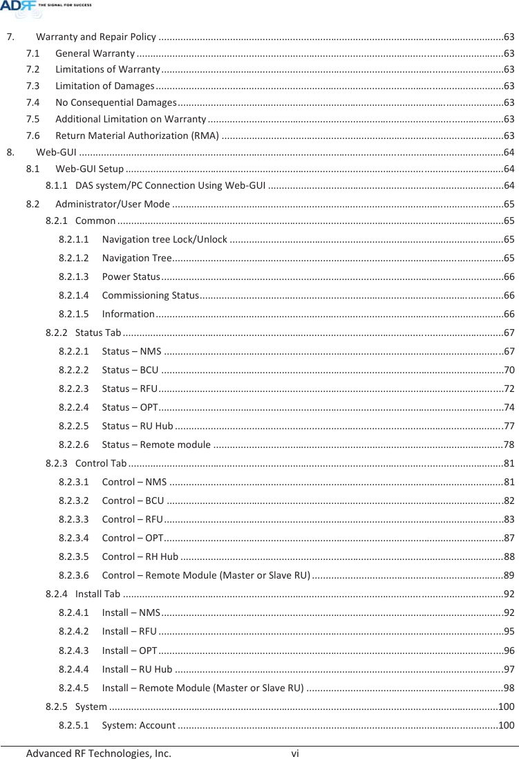
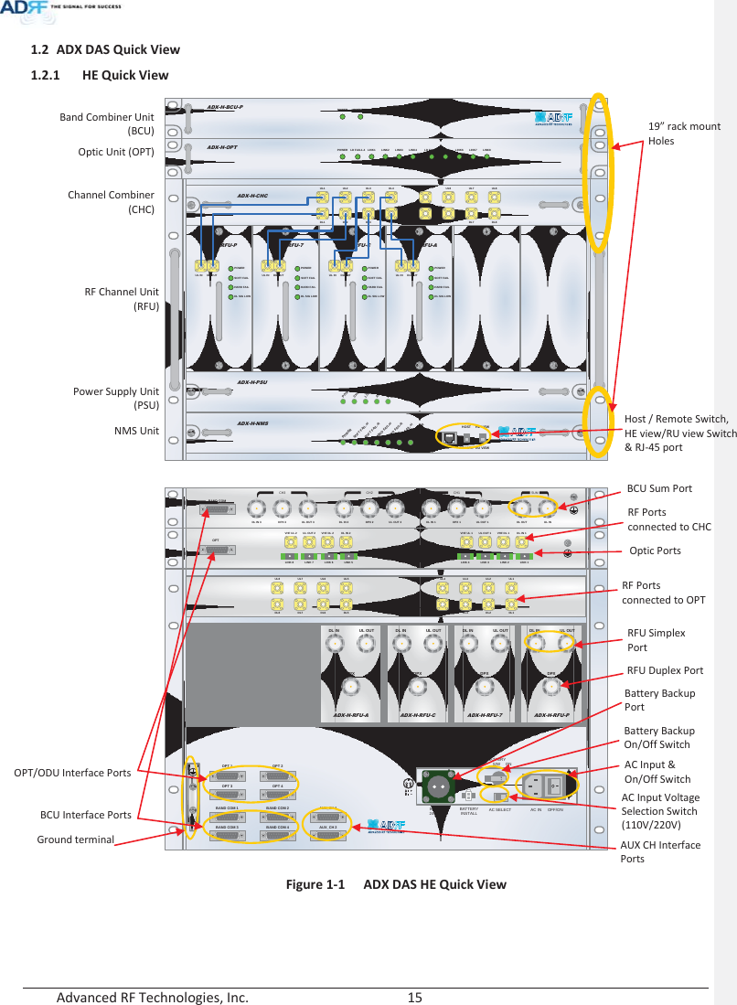
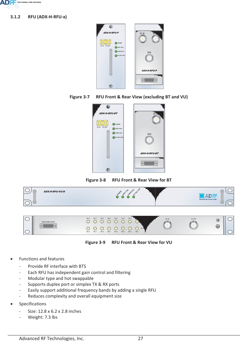
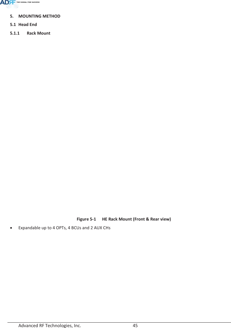
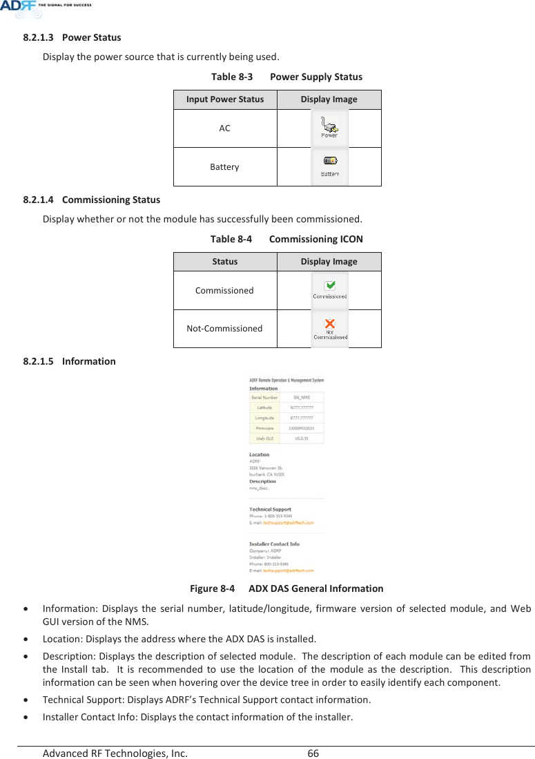
![Advanced RF Technologies, Inc. 24 3. ADX OVERVIEW 3.1 Head End The head end unit must always be connected to the Base Station using a direct cabled connection. This system has not been approved for use with a wireless connection via server antenna to the base station. Head end components include: ADX-H-NMS (Network Management System) ADX-H-CHC (Head End Channel Combiner) ADX-H-PSU (Head End Power Supply) Up to [4] ADX-H-BCU (Band Combiner Unit) Up to [8] ADX-H-RFU-x (RF Unit) Up to [4] ADX-H-OPT (Optical Unit) x Specifications - Size: 19.0 x 14.6 x 12.2 inches (482 x 370 x 311 mm) - Weight: 83.7 lbs (38.0 Kg)@4 RFU, CHC-H, PSU and NMS - Power Consumption: 52W@4 RFU, 1 OPT and NMS, 28W@1 RFU, 1 OPT and NMS - Power Input: 110VAC or -48VDC(optional) - Supports the ADRF-BBU for external battery backup solution ADX-H-NMSPOWERSOFTFAIL-HSOFTFAIL-RHARD FAIL-HHARD FAIL-RLINKFAIL-HLINKFAIL-RHOST HE VIEWREMOTE RU VIEWADX-H-PSUPOWERCHGSTSLOWBATTACFAILDCFAILDL OUTUL INHARD FAILDL SIG LOWSOFT FAILPOWERADX-H-RFU-PDL OUTUL INHARD FAILDL SIG LOWSOFT FAILPOWERADX-H-RFU-7DL OUTUL INHARD FAILDL SIG LOWSOFT FAILPOWERADX-H-RFU-CDL OUTUL INHARD FAILDL SIG LOWSOFT FAILPOWERADX-H-RFU-AADX-H-CHCUL1 UL2 UL3 UL4DL1 DL2 DL3 DL4UL5 UL6 UL7 UL8DL5 DL6 DL7 DL8LD FAIL5-8 LINK5 LINK6 LINK7 LINK8LD FAIL1-4 LINK1 LINK2 LINK3 LINK4POWERADX-H-OPTSOFT FAILPOWERADX-H-BCU-P Figure 3-1 Head End Front View ָ֦ [Y3]: ɼ 15/02/03](https://usermanual.wiki/ADRF-KOREA/ADX-R-BT/User-Guide-2525468-Page-24.png)
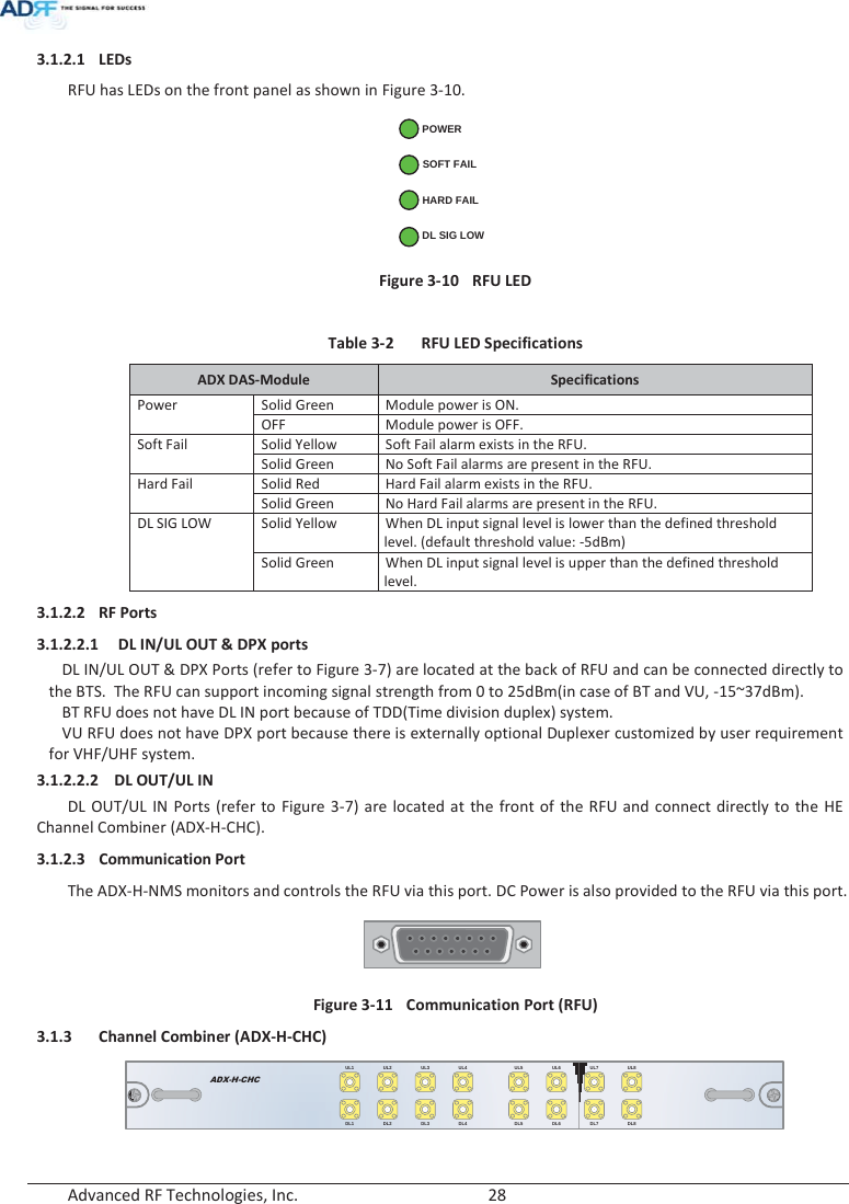
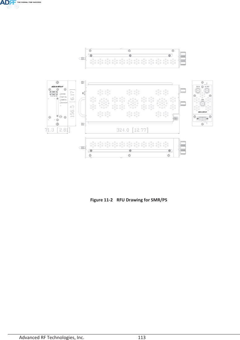
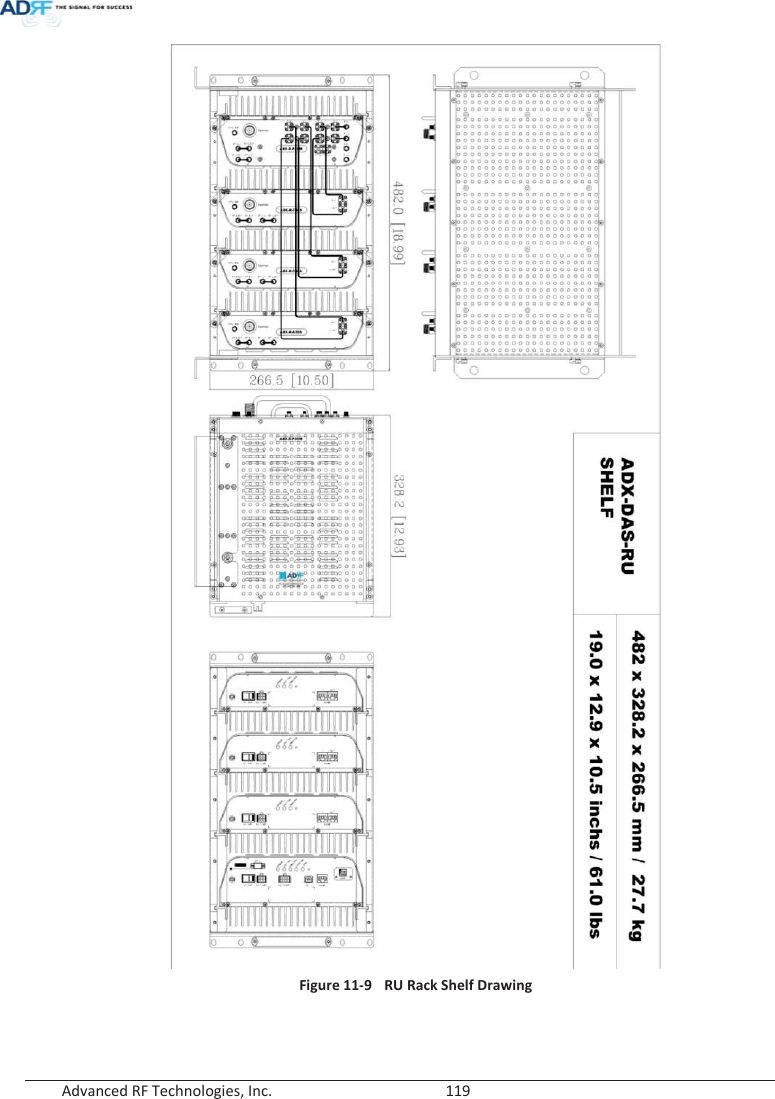
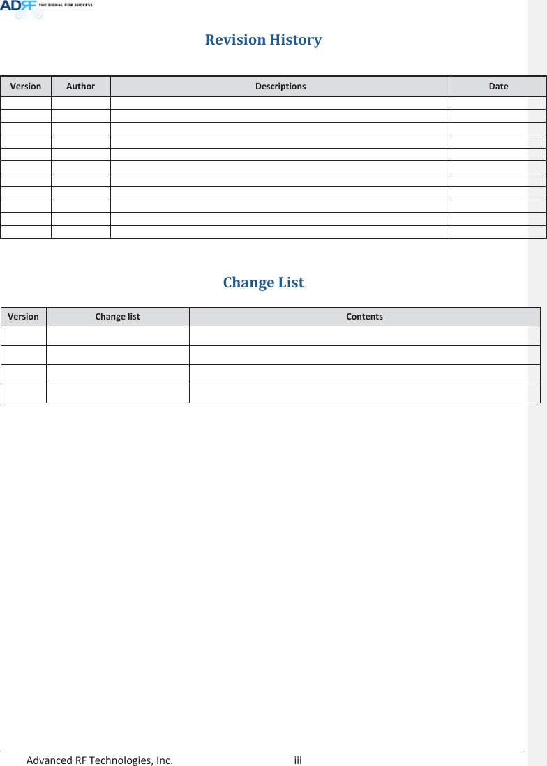
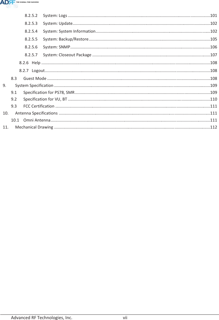
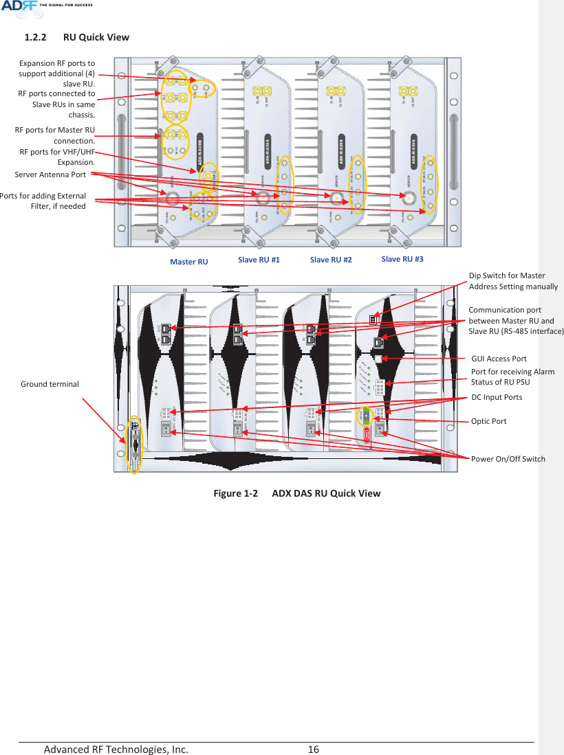
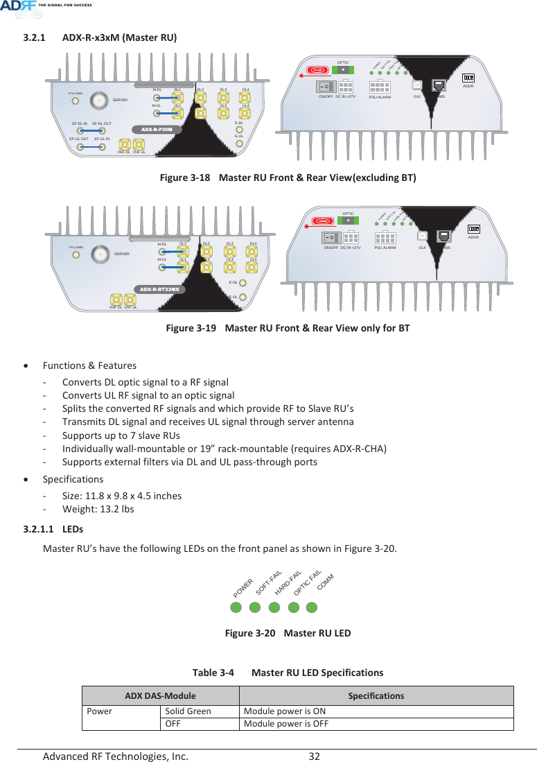
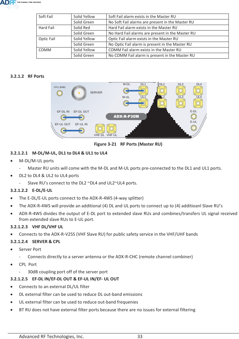
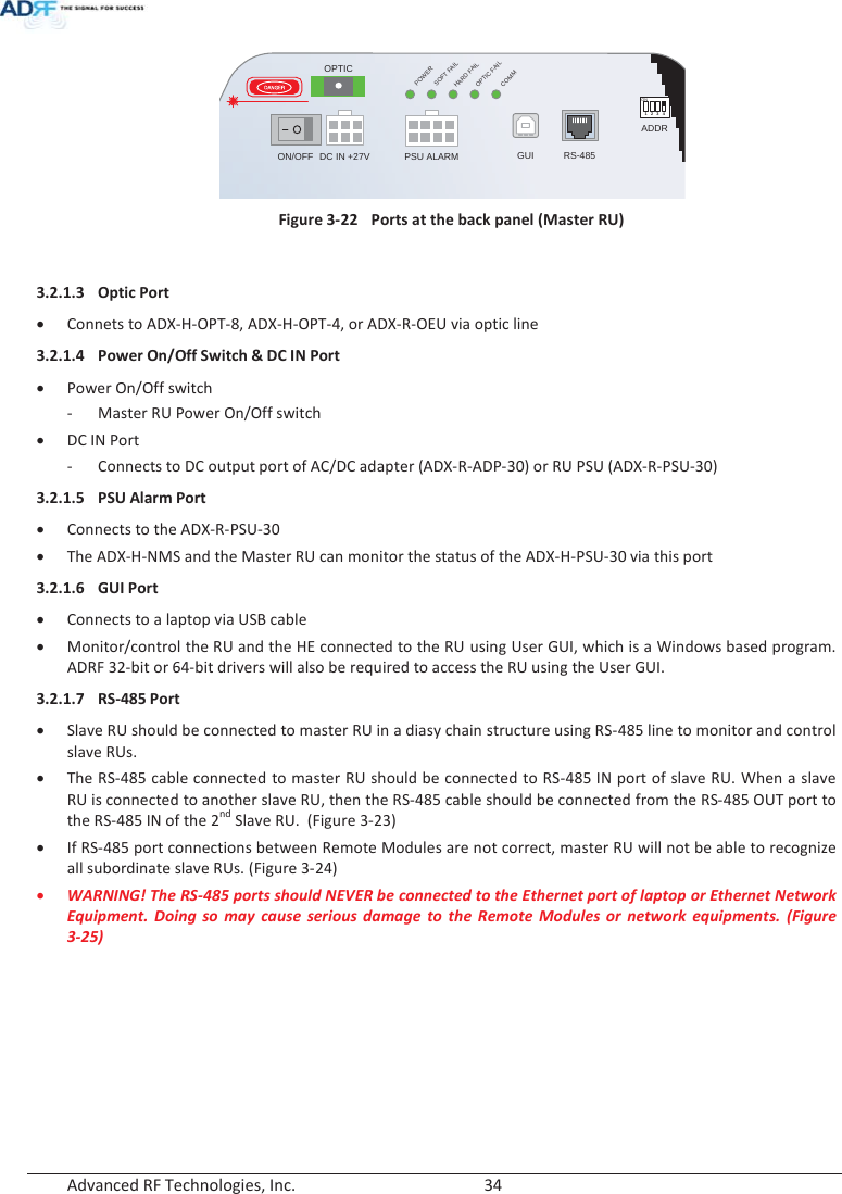
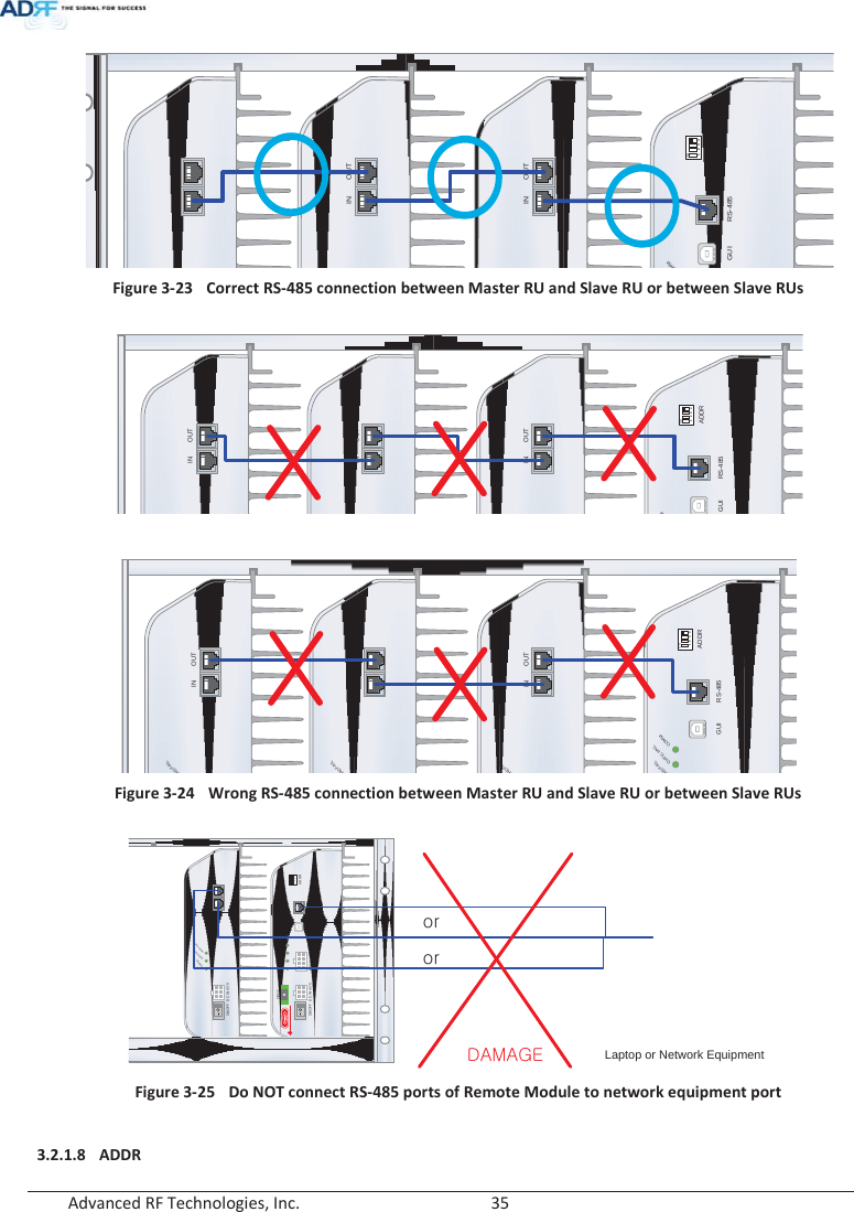
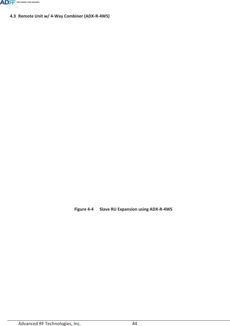
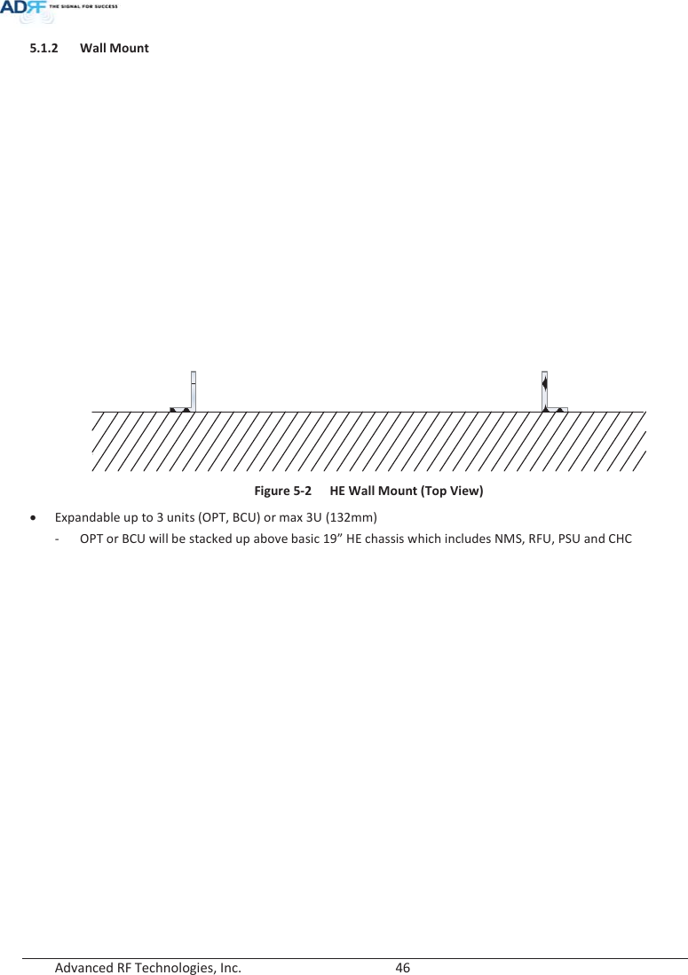
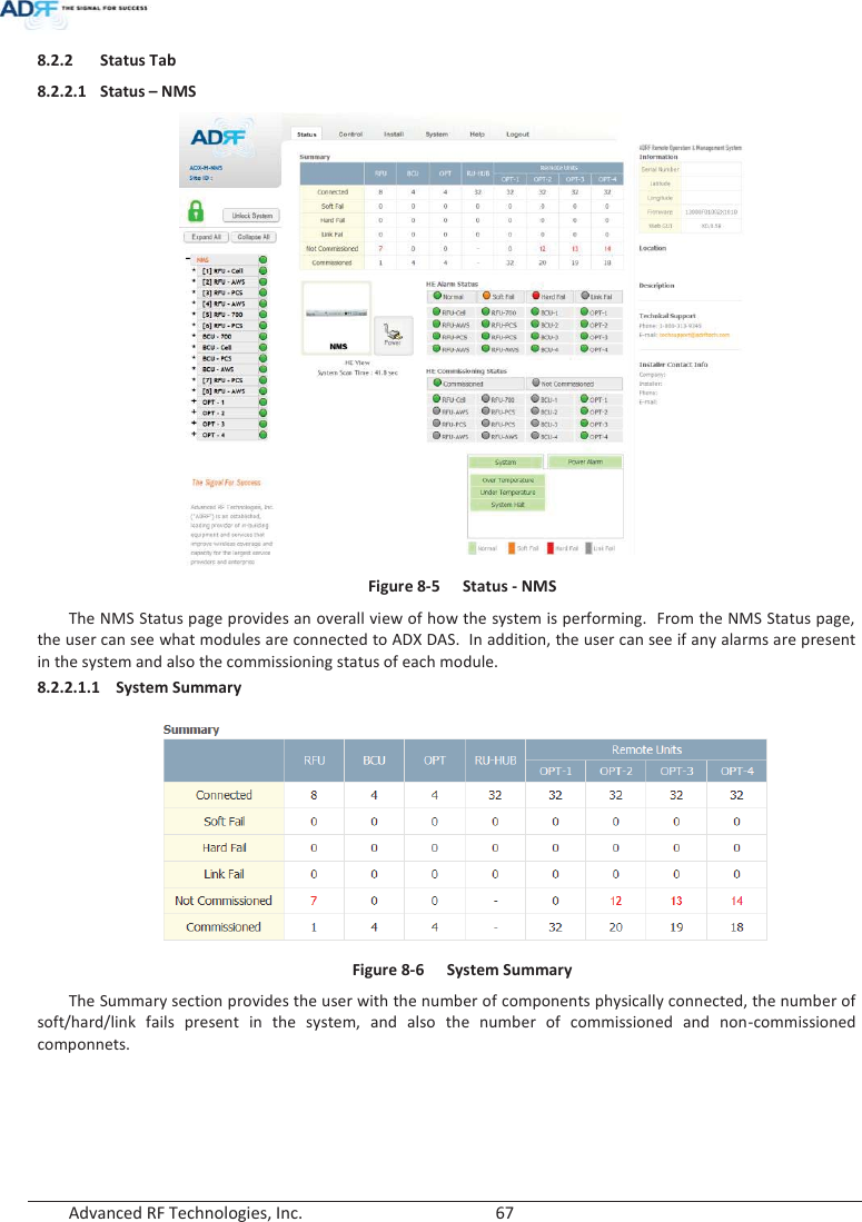
![Advanced RF Technologies, Inc. 31 The combined downlink signal received from ADX-H-CHC is transferred to the DL IN 1(or 2) at the back of OPT. The UL OUT port connects any of the ports on back of the ADX-H-CHC labeled UL 1 ~8. 3.1.4.2.2 VHF DL/VHF UL VHF DL/UHF UL ports are used to support Public Safety in the VHF & UHF frequency bands. VHF/UHF signals for Public Safety bypass the ADX-H-CHC and connect directly to the VHF DL/UHF UL ports of the ADX-H-OPT. 3.2 Remote Unit The remote unit is composed of a (1) Master RU and up to (7) Slave RU’s (ADX-R-4WS is required when connecting more than 3 Slave RU’s). A power source, either the ADX-R-ADP-30 (supports [1] Master/Slave RU) or the ADX-R-PSU-30 (supports up to [8] Master/Slave RU) is required. x Specifications - Size: 19.0 x 12.9 x 10.5 inches - Weight: 61.0 lbs - Power Input: 110VAC or -48VDC (optional) Figure 3-16 RU Front View Figure 3-17 RU Rear View DC IN +27VON/OFFOUTPOWERSOFTFAILHARDFAILINDC IN +27VON/OFFOUTPOWERSOFTFAILHARDFAILINDC IN +27VON/OFFOUTPOWERSOFTFAILHARDFAILINPOWERSOFTFAILHARDFAILCOMMOPTIC FAILDC IN +27V PSU ALARM RS-485GUIOPTICON/OFFON1234ADDRkhunly](https://usermanual.wiki/ADRF-KOREA/ADX-R-BT/User-Guide-2525468-Page-31.png)

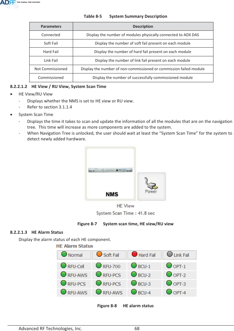
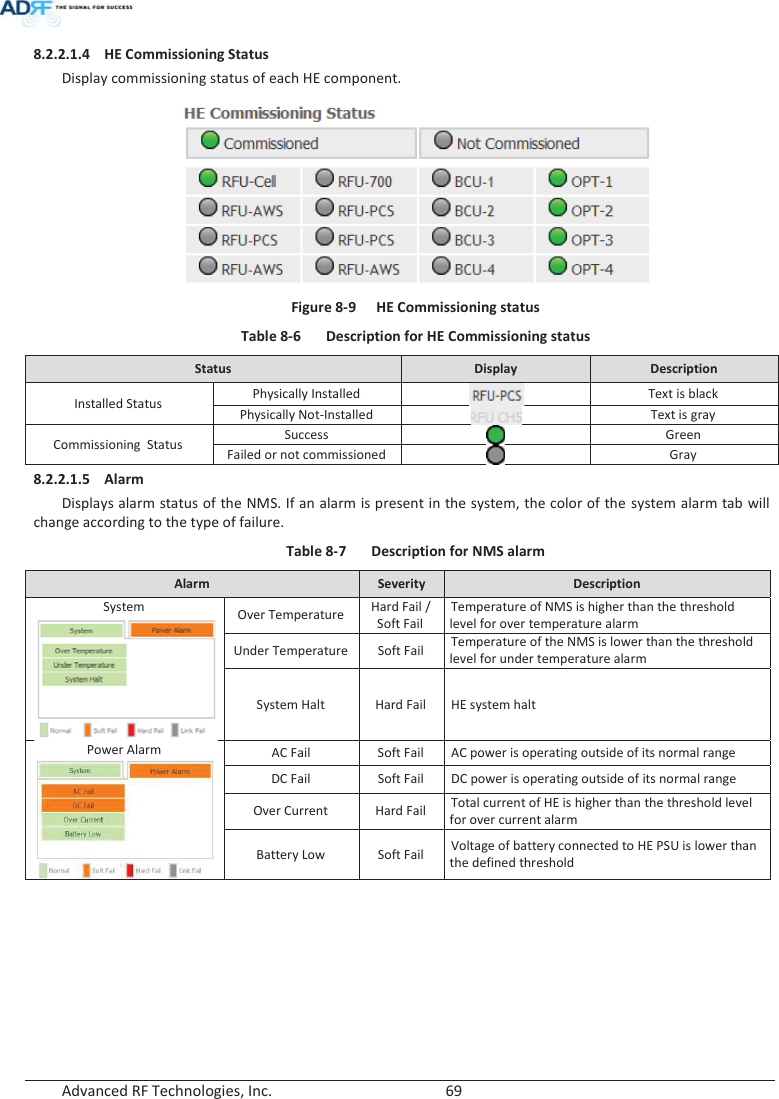

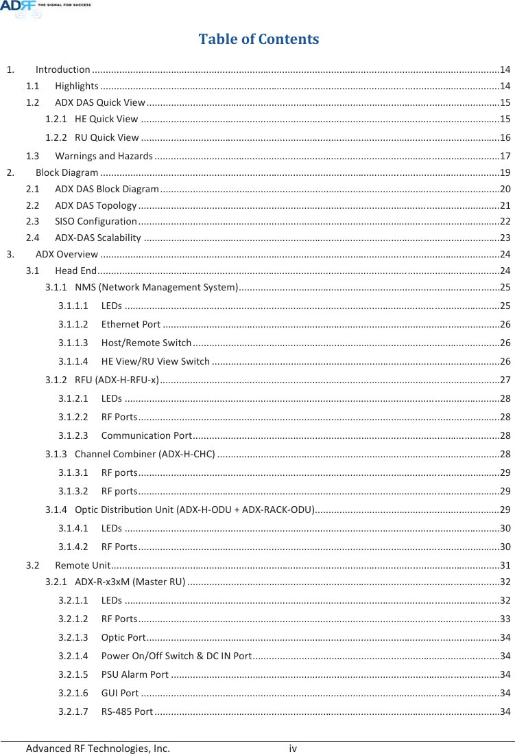
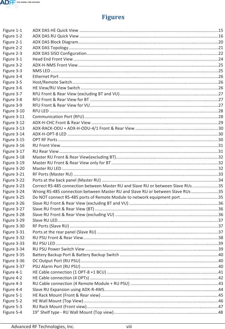
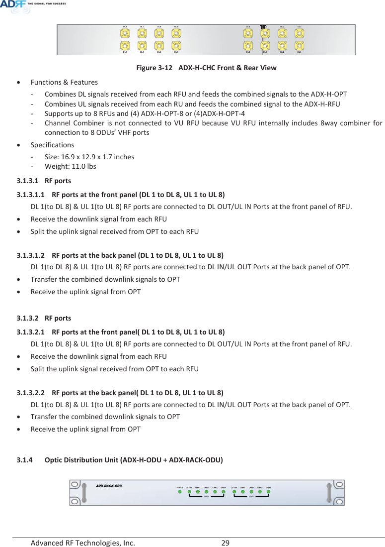
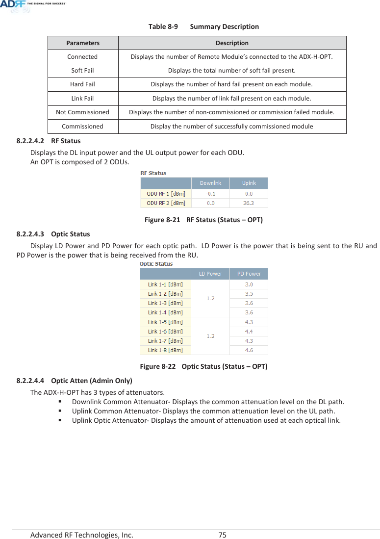
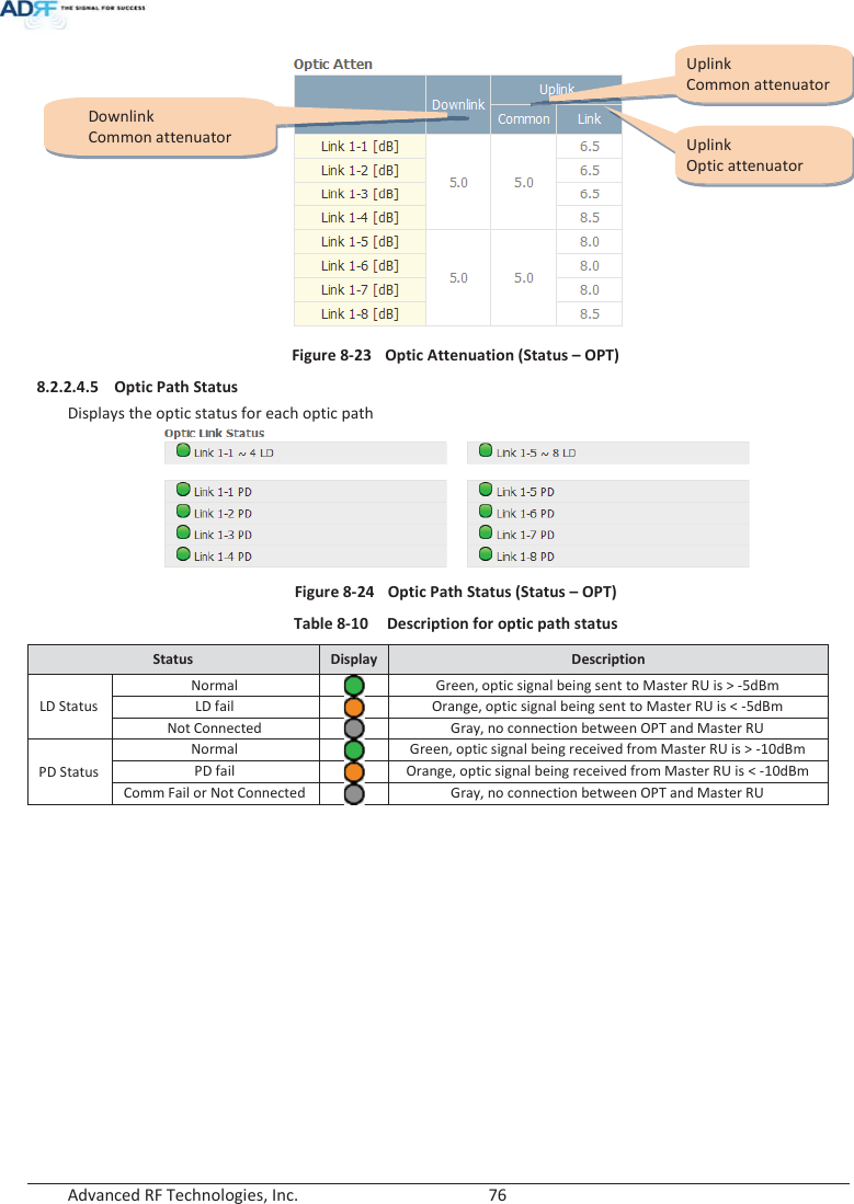
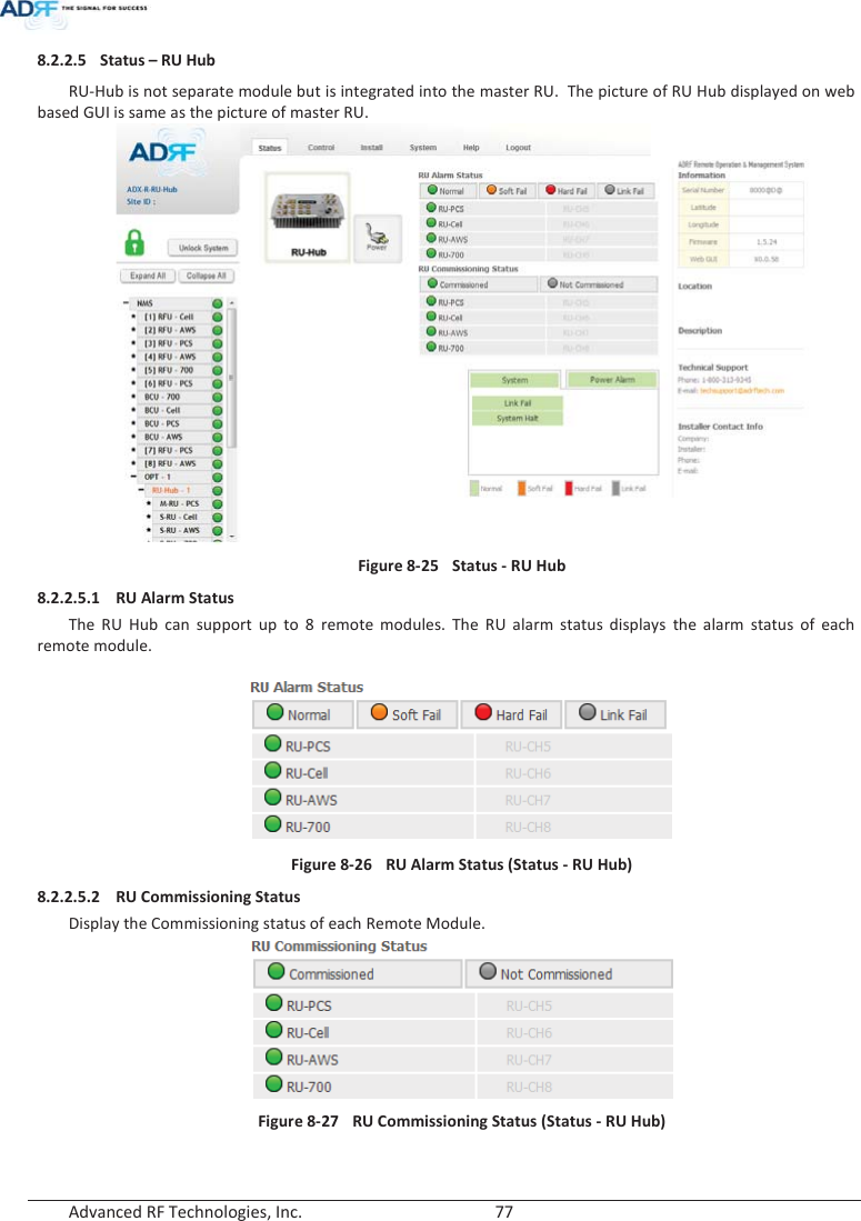
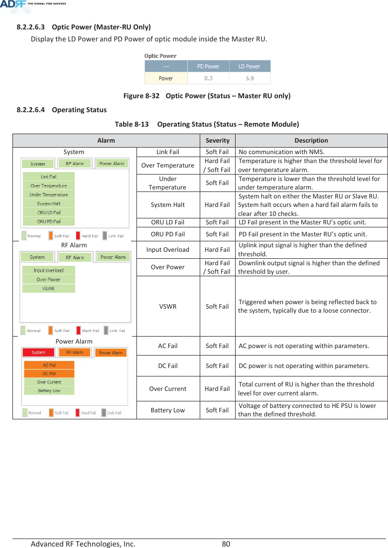
![Advanced RF Technologies, Inc. 73 Figure 8-18 Power & Gain Display (User) x Input [dBm]: Displays the Downlink RF input level which comes from the ADX-H-BCU, BTS. This value should be between 0 to 25 dBm. x ALC Atten [dB]: The amount of attenuation that is being used by the system when ALC is active. x Atten [dB]: The amount of attenuation that has been set manually by the user. x Output [dBm]: The downlink/uplink output power of the RFU and NOT the output power of the RU. 8.2.2.3.3 Alarm Displays System, RF, and Power Alarms. If an alarm is present in the system, then the color of the tab will change according to the type of failure. Table 8-8 RFU Alarm Status Alarm Severity Description System Link Fail Soft Fail A component is physically connected, but the NMS is unable to communicate with it. Over Temperature Hard Fail / Soft Fail The temperature of NMS is higher than the threshold level for over temperature alarm. Under Temperature Soft Fail The temperature of NMS is lower than the threshold level for under temperature alarm. System Halt Hard Fail System will go into a “System Halt” state when a hard fail alarm does not clear after 10 checks. System Halt can only be cleared with a power cycle, reboot, or factory settings. RF Alarm DL Signal not detected Soft Fail Downlink input signal is lower than the defined threshold by user. DL Signal Low Soft Fail Downlink input signal is lower than the defined threshold by user. Input Overload Hard Fail / Soft Fail Downlink input signal is higher than the defined threshold. Overpower Hard Fail / Soft Fail Uplink output signal is higher than the defined threshold by user. Power Alarm AC Fail Soft Fail AC power is not operating within parameters. DC Fail Soft Fail DC power is not operating within parameters. Over Current Hard Fail Total current of HE is higher than the threshold level for over current alarm. Battery Low Soft Fail Voltage of battery connected to HE PSU is lower than the defined threshold.](https://usermanual.wiki/ADRF-KOREA/ADX-R-BT/User-Guide-2525468-Page-73.png)
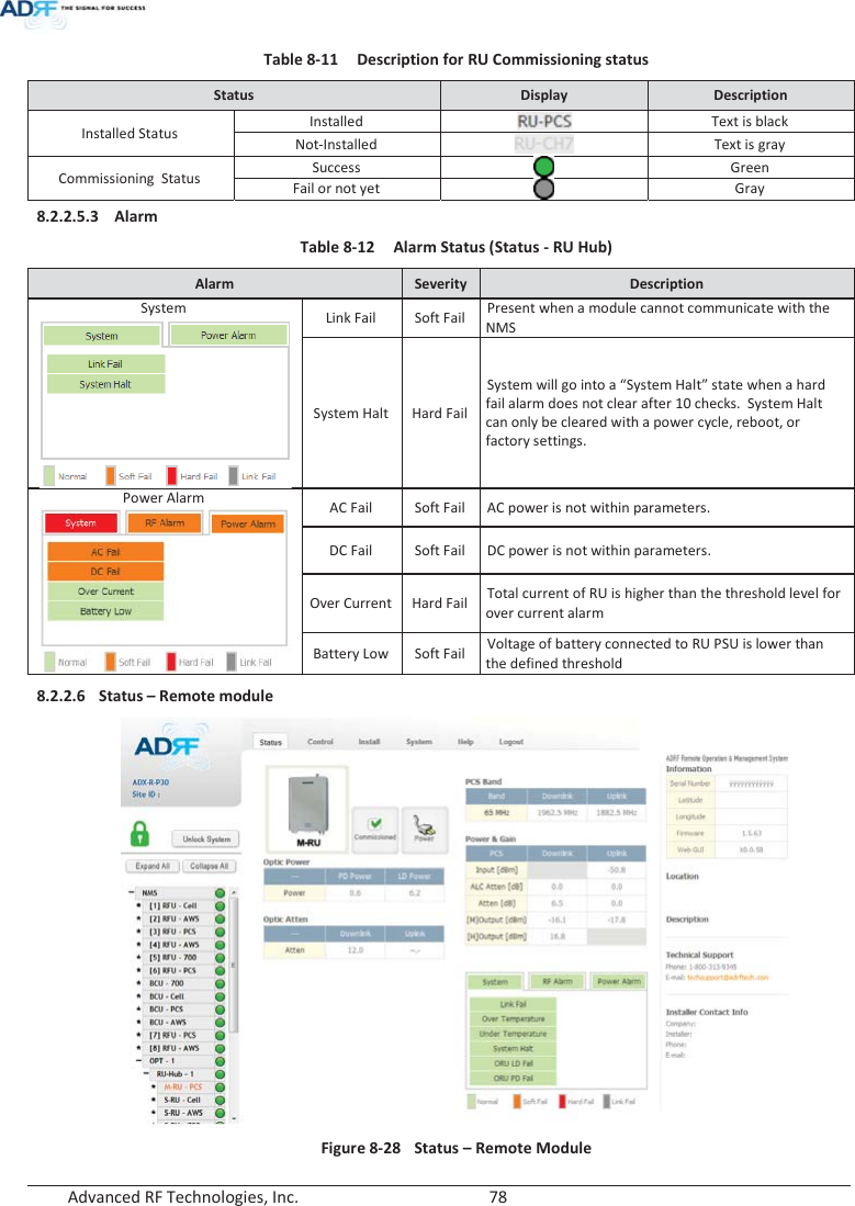
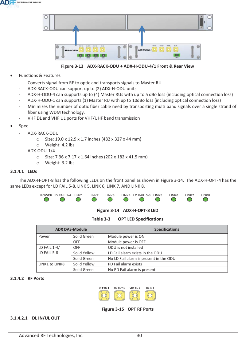
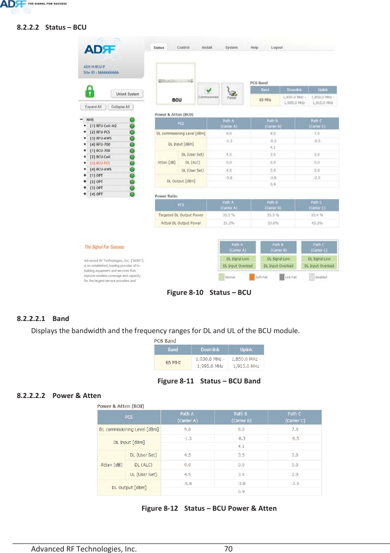
![Advanced RF Technologies, Inc. 79 8.2.2.6.1 Band Display the spectrum that is being used. The band column displays the bandwidth that has been used. The downlink column displays the center frequency of the used downlink band. The uplink column displays the center frequency of the used uplink band. Figure 8-29 PCS Band Information (Status – Remote Module) 8.2.2.6.2 Power & Gain (Admin/User) Display the Downlink output, Downlink/Uplink Attenuation, and Uplink Input/output. Figure 8-30 Power & Gain (Admin) Figure 8-31 Power & Gain (User) x Admin o Input [dBm]: Displays the RF input level for Uplink only for the Remote Module. o ALC Atten [dB]: The amount of attenuation used when ALC is activate. o Atten [dB]: The amount of attenuation manually set by the user. o [M]Output [dBm]: Output power of RF transceiver (1st stage amplification). o [H]Output [dBm]: Output power of downlink HPA (2nd stage amplification). x User o Input [dBm]: Displays the RF input level for Uplink only for the Remote Module. o Atten [dB]: The amount of attenuation manually set by the user. o Output [dBm]: Displays the total composite output power.](https://usermanual.wiki/ADRF-KOREA/ADX-R-BT/User-Guide-2525468-Page-79.png)
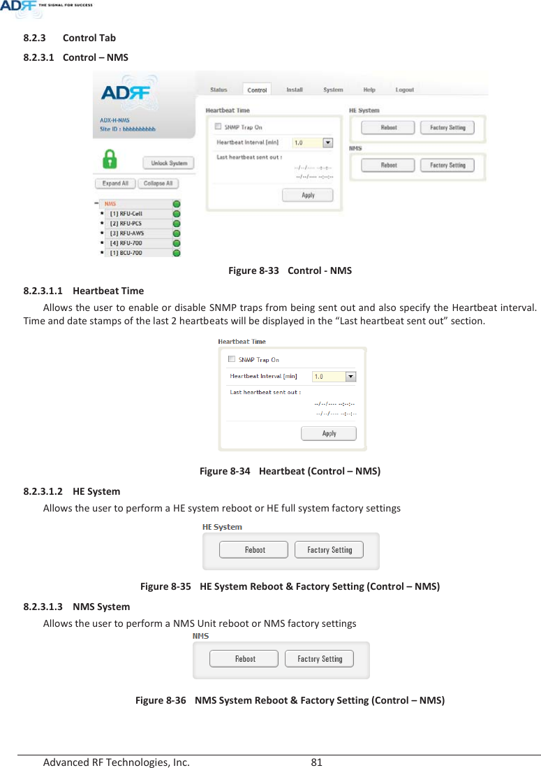
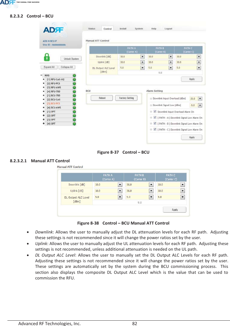
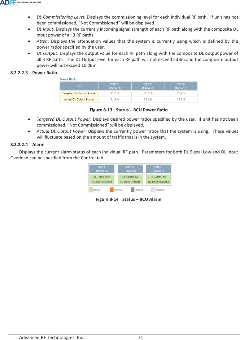
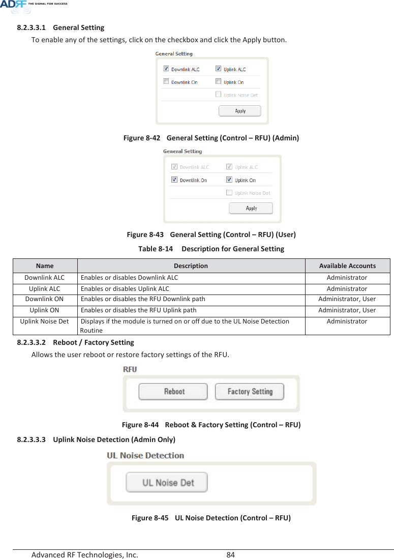
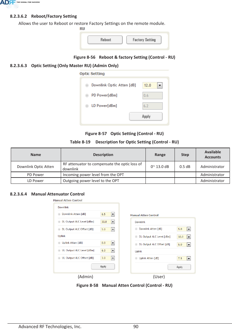
![Advanced RF Technologies, Inc. 83 8.2.3.2.2 Reboot / Factory Setting Allows the user reboot or restore factory settings of the BCU. Figure 8-39 Control – BCU Reboot/Factory Setting 8.2.3.2.3 Alarm Setting Figure 8-40 Control – BCU Alarm Setting x Downlink Input Overload: Allows the user to specify the level at which the DL Input Overload alarm is triggered. Values range from 0 dBm to +25 dBm. x Downlink Signal Low: Allows the user to specify the level at which the DL Signal Low alarm is triggered. Values range from -10 dBm to +20 dBm. x Downlink Input Overload Alarm On: Allows to user to enable or disable the Input Overload Alarm x [Path – A/B/C] Downlink Signal Low Alarm On: Allows the user to enable or disable the DL Signal Low alarm for each RF path. 8.2.3.3 Control – RFU Figure 8-41 Control - RFU](https://usermanual.wiki/ADRF-KOREA/ADX-R-BT/User-Guide-2525468-Page-83.png)
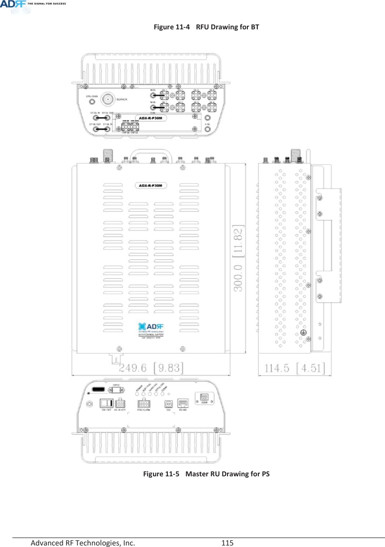
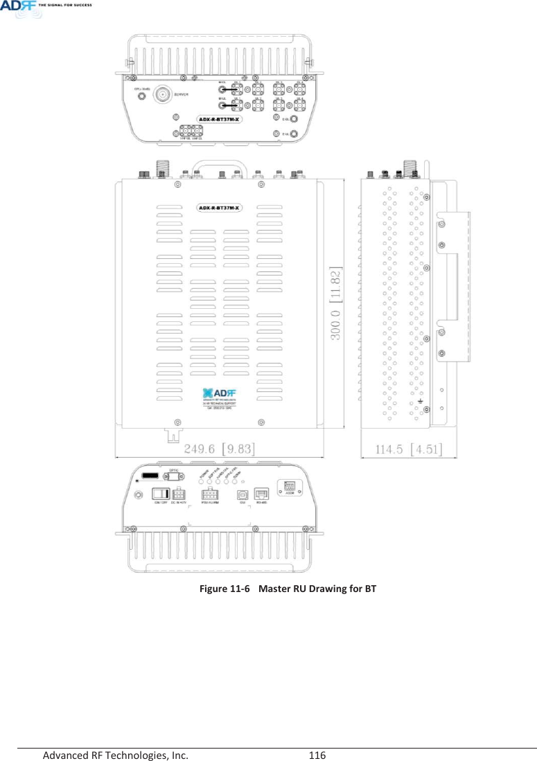
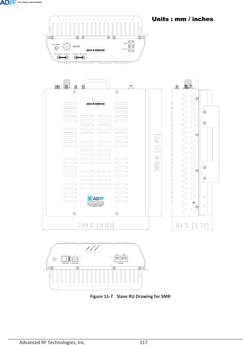
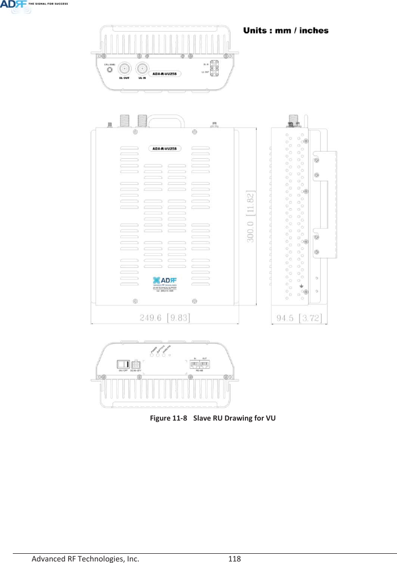
![Advanced RF Technologies, Inc. 109 9. SYSTEM SPECIFICATION 9.1 Specification for PS78, SMR Parameters PS78 SMR Frequency Downlink P7 763-775MHz S8 851-869MHz S8 851-869MHz S9 935-940MHz Uplink P7 793-805MHz S8 806-824MHz S8 806-824MHz S9 896-901MHz Input Power Range 0~+25dBm Gain Downlink 5~30dB, 0.5dB step, ATT range: 0~25dB Uplink -5~30dB, 0.5dB step, ATT range: 0~35dB Maximum Output Power1 Downlink at RU 30dBm±2dB Uplink at HE -15dBm±2dB Noise Figure < 10dB@maximum gain VSWR < 1:1.5 Optical Loss0~5dBoSystem Delay < 2us Spurious Meet FCC rules, 3GPP TS 36.104, 3GPP2 C.S0010-C Nominal Band/BW for Industry Canada Downlink P7 A~B MHz/bw MHz S8 C~D MHz S8 E~F MHz S9 G~H MHz Uplink P7 I~J MHz S8 K~L MHz S8 M~N MHz S9 O~P MHz Dimension (WXDXH) Head-End Shelf 19.0 x 14.6 x 12.2 inches (482 x 370 x 311 mm) Remote-Unit Shelf 19.0 x 12.9 x 10.5 inches (482 x 328.2 x 266.5 mm) Master RU 11.8 x 9.8 x 4.5 inches (300 x 249.6 x 114.5 mm) Slave RU 11.8 x 9.8 x 3.7 inches (300 x 249.6 x 94.5 mm) Weight Head-End Shelf 83.7 lbs (38.0 Kg) @4 RFU, CHC-H, PSU and NMS Remote-Unit Shelf 61.0 lbs (27.7 kg) @ 1 master RU, 3 Slave RU Master RU 13.2 lbs (6.0 kg) Slave RU 11.7 lbs (5.3 kg) Operating Temperature 14-122qF(-10-50°C) Operating Humidity 5~90%RH Power Input 110/220V, 50-60Hz, 24V or -48V DC(optional) Power consumption Head-End 52W@4 RFU, 1 OPT and NMS 28W@1 RFU, 1 OPT and NMS 1 The Manufacturer's rated output power of this equipment is for single carrier operation. For situations when multiple carrier signals are present, the rating would have to be reduced by 3.5 dB, especially where the output signal is re-radiated and can cause interference to adjacent band users. This power reduction is to be by means of input power or gain reduction and not by an attenuator at the output of the device ָ֦ [Y4]: ݨࢿԻ ্ࢽଜ܈۰ ̛ࡁঐଢТЬ. 15/02/03](https://usermanual.wiki/ADRF-KOREA/ADX-R-BT/User-Guide-2525468-Page-109.png)
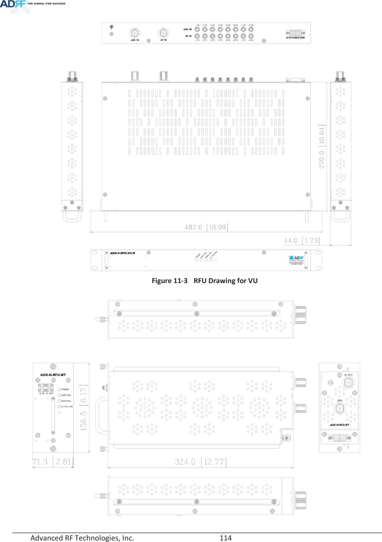
![Advanced RF Technologies, Inc. 110 Remote-Unit 60W 53W Network Management System Ethernet(RJ45) RF connector Head-End N-type(Female) Remote-Unit N-type(Female) Input/output Impedance 50: 9.2 Specification for VU, BT Parameters VU BT TBD Frequency Downlink VHF 136-174MHz 2496-2690MHz (BRS TDD) UHF 396-512MHz Uplink VHF 136-174MHz 2496-2690MHz (BRS TDD) UHF 396-512MHz Input Power Range -15~+37dBm Gain Downlink -12~40dB, 0.5dB step, ATT range: 0~52dB 0~52dB, 0.5dB step, ATT range: 0~52dB Uplink -15~20dB, 0.5dB step, ATT range: 0~35dB -5~30dB, 0.5dB step, ATT range: 0~35dB Maximum Output Power2 Downlink at RU 25dBm±2dB 37dBm±2dB Uplink at HE -15dBm±2dB -15dBm±2dB Noise Figure< 10dB@maximum gainVSWR < 1:1.5 Optical Loss 0~5dBo System Delay < 2us Spurious Meet FCC rules, 3GPP TS 36.104, 3GPP2 C.S0010-C Nominal Band/BW for Industry Canada Downlink VHF A~B MHz /bw MHz NA UHF E~F MHz UplinkVHF C~D MHzNA UHF G~H MHz Dimension (WXDXH) Master RU 11.8 x 9.8 x 4.5 inches (300 x 249.6 x 114.5 mm) Slave RU 11.8 x 9.8 x 3.7 inches (300 x 249.6 x 94.5 mm) Weight Master RU 13.2 lbs (6.0 kg) Slave RU 11.7 lbs (5.3 kg) Operating Temperature 14-122qF(-10-50°C) Operating Humidity 5~90%RH Power Input 110/220V, 50-60Hz, 24V or -48V DC(optional) Power consumptioHead-End 52W@4 RFU, 1 OPT and NMS 28W@1 RFU, 1 OPT and NMS 2 The Manufacturer's rated output power of this equipment is for single carrier operation. For situations when multiple carrier signals are present, the rating would have to be reduced by 3.5 dB, especially where the output signal is re-radiated and can cause interference to adjacent band users. This power reduction is to be by means of input power or gain reduction and not by an attenuator at the output of the device ָ֦ [Y5]: ݨࢿԻ ্ࢽଜ܈۰ ̛ࡁঐଢТЬ. 15/02/03](https://usermanual.wiki/ADRF-KOREA/ADX-R-BT/User-Guide-2525468-Page-110.png)
![Advanced RF Technologies, Inc. 111 n Remote-Unit 32W 87W Network Management System Ethernet(RJ45) RF connector Head-End N-type(Female) Remote-Unit N-type(Female) Input/output Impedance 50: 9.3 FCC Certification Item FCC Certification ADX-R-SMR Part 20, Part 90 ADX-R-78P Part 90 ADX-R-BT Part 20 10. ANTENNA SPECIFICATIONS 10.1 Omni Antenna Frequency 698-960MHz 1710-2690MHz Polarization Vertical Gain 2dBi 3dBi VSWR <1.7:1 <1.5:1 Impedance 50: Power Rating 50W Note. Please note that integrators, end-users or installers should not use the antenna with more gain than 3dBi to meet the RF exposure requirement. ָ֦ [Y6]: FCC part ָ̛ 15/02/03 ָ֦ [Y7]: ߇੨Ο ̍ʸ ɼ 15/02/03](https://usermanual.wiki/ADRF-KOREA/ADX-R-BT/User-Guide-2525468-Page-111.png)