ADRF KOREA ADX-R-SMR DAS (Distributed Antenna System) User Manual ADX DAS
ADRF KOREA, Inc. DAS (Distributed Antenna System) ADX DAS
Contents
- 1. User Manual_Installaion Manual rev Part1
- 2. User Manual_Installaion Manual rev Part2
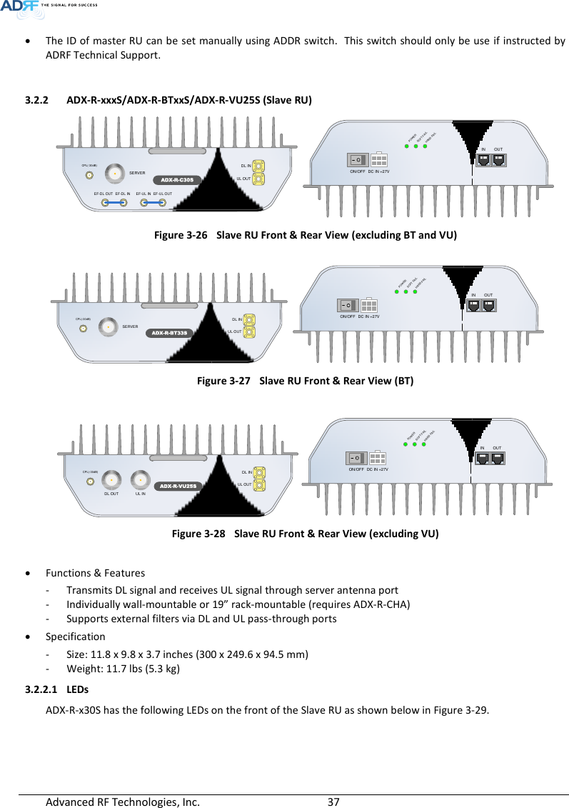
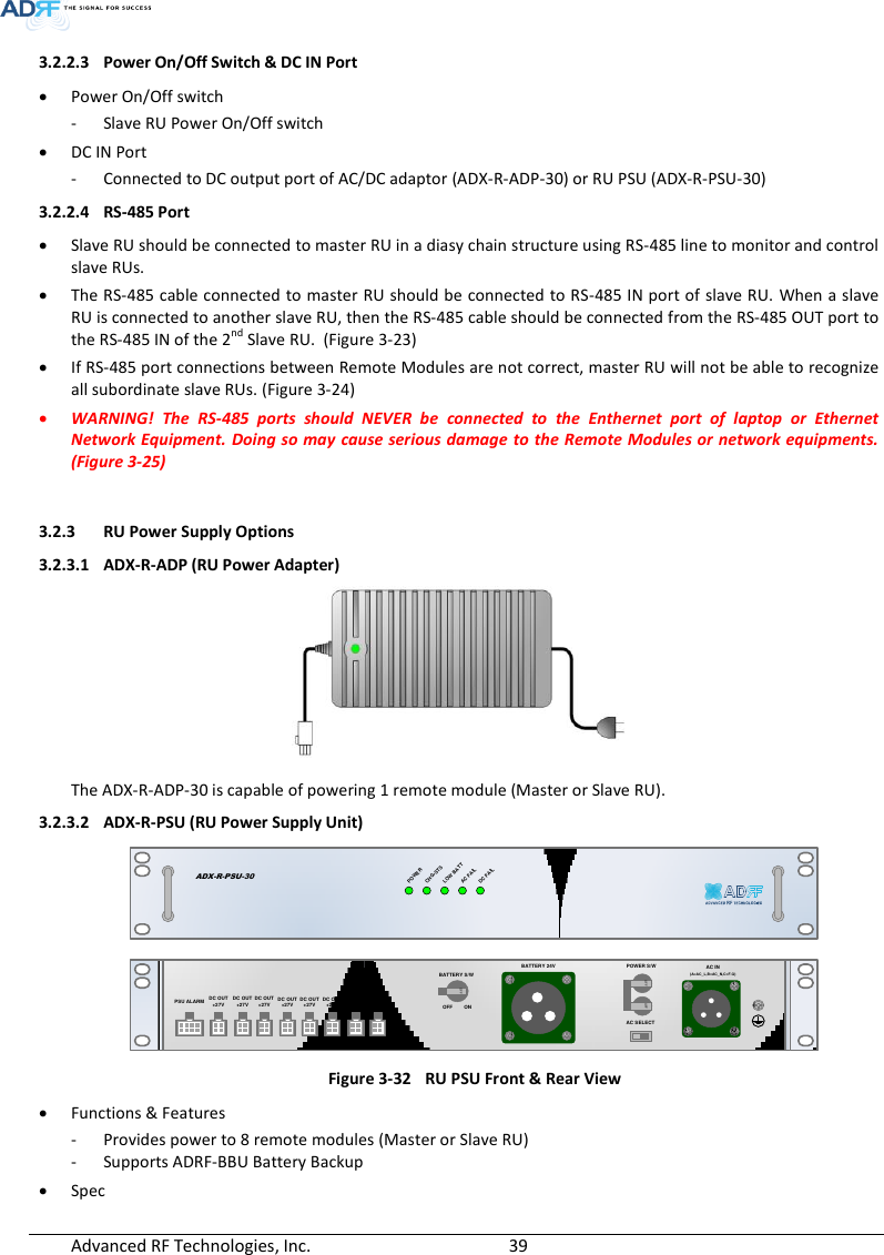
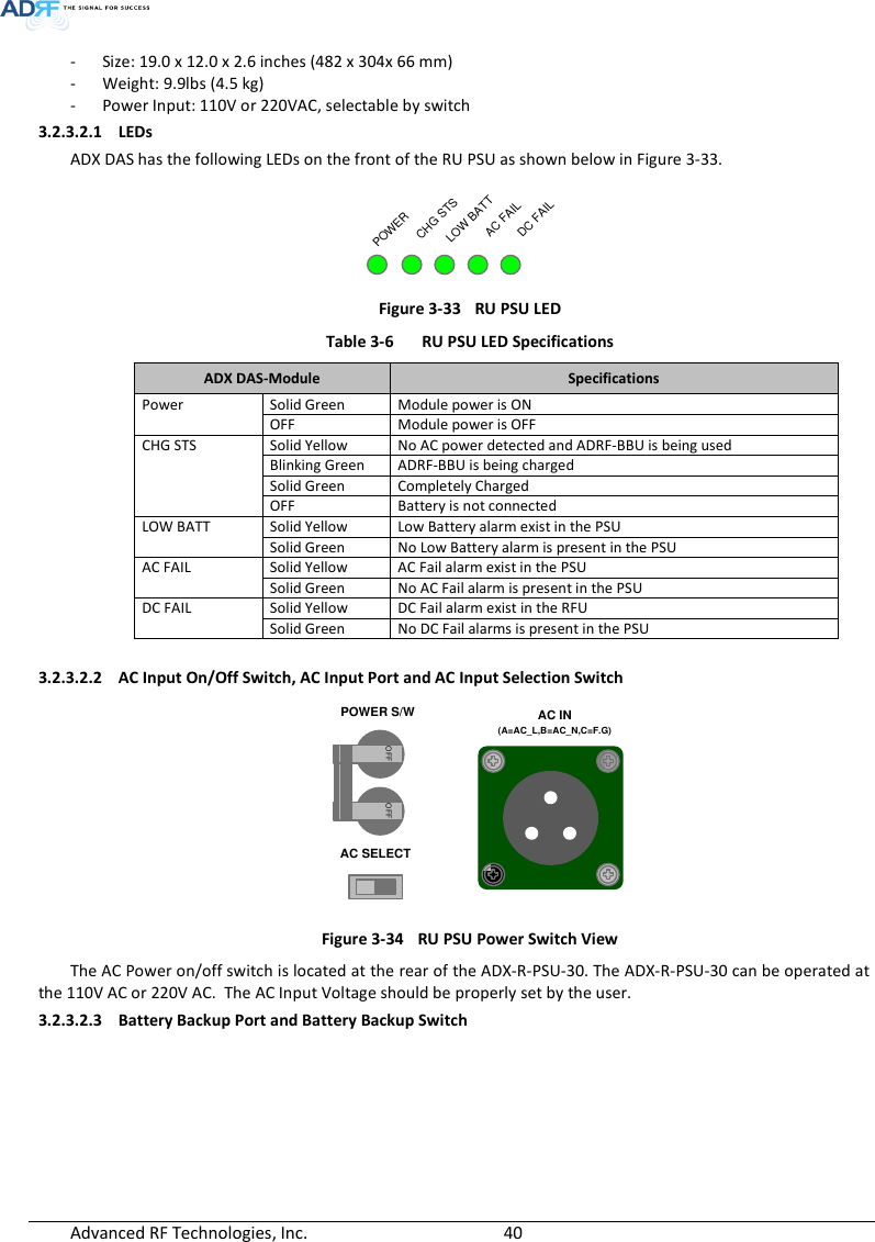
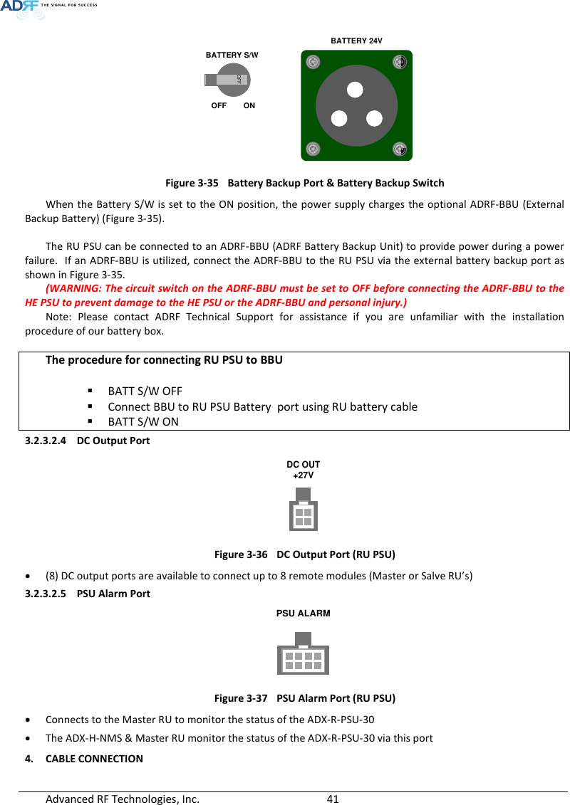
- 3. User Manual_Installaion Manual rev Part3
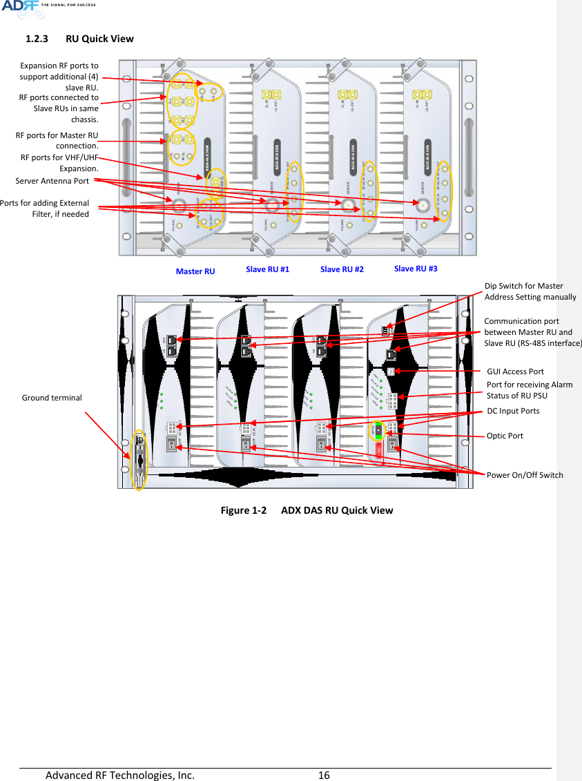
User Manual_Installaion Manual rev Part1

![Advanced RF Technologies, Inc. 17 1.3 Warnings and Hazards Lithium Battery: CAUTION. RISK OF EXPLOSION IF BATTERY IS REPLACED BY INCORRECT TYPE. DISPOSE OF USED BATTERIES ACCORDING TO INSTRUCTIONS. Opening or tampering the ADX DAS will void all warranties. WARRANTY Actual separation distance is determined upon gain of antenna used. Please maintain a minimum safe distance of at least 50 cm while operating near the donor and the server antennas. RF EXPOSURE & ANTENNA PLACEMENT Guidelines Working with the ADX DAS while in operation, may expose the technician to RF electromagnetic fields that exceed FCC rules for human exposure. Visit the FCC website at www.fcc.gov/oet/rfsafety to learn more about the effects of exposure to RF electromagnetic fields. WARNING! EXPOSURE TO RF Opening the ADX DAS could result in electric shock and may cause severe injury. WARNING! ELECTRIC SHOCK 메모 [H1]: Donor antenna 설치에 대한 문구 삭제. (HK)](https://usermanual.wiki/ADRF-KOREA/ADX-R-SMR.User-Manual-Installaion-Manual-rev-Part1/User-Guide-2625928-Page-17.png)
![Advanced RF Technologies, Inc. 18 WANRNING. THIS is NOT a CONSUMER device. It is designed for installation by FCC LICENSEES and QUALIFIED INSTALLERS. You MUST have an FCC LICENSE or express consent of an FCC Licensee to operate this device. You MUST register Class B signal boosters (as defined in 47 CFR 90.219) online at www.fcc.gov/signal-boosters/registration. Unauthorized use may result in significant forfeiture penalties, including penalties in excess of $100,000 for each continuing violation. FCC Part 90 Class B WANRNING. THIS is NOT a CONSUMER device. It is designed for installation by FCC LICENSEES and QUALIFIED INSTALLERS. You MUST have an FCC LICENSE or express consent of an FCC Licensee to operate this device. Unauthorized use may result in significant forfeiture penalties, including penalties in excess of $100,000 for each continuing violation. FCC Part 20 NOTE: This equipment has been tested and found to comply with the limits for a Class A digital device, pursuant to part 15 of the FCC Rules. These limits are designed to provide reasonable protection against harmful interference when the equipment is operated in a commercial environment. This equipment generates, uses, and can radiate radio frequency energy and, if not installed and used in accordance with the instruction manual, may cause harmful interference to radio communications. Operation of this equipment in a residential area is likely to cause harmful interference in which case the user will be required to correct the interference at their own expense. FCC Part 15 Class A Ethernet Instructions: This equipment is for indoor use only. All cabling should be limited to inside the building. 메모 [Y2]: 추가 15/02/03 메모 [Y3]: 추가 15/02/03](https://usermanual.wiki/ADRF-KOREA/ADX-R-SMR.User-Manual-Installaion-Manual-rev-Part1/User-Guide-2625928-Page-18.png)

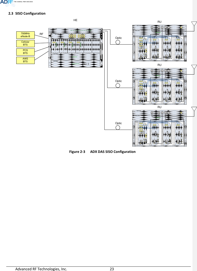
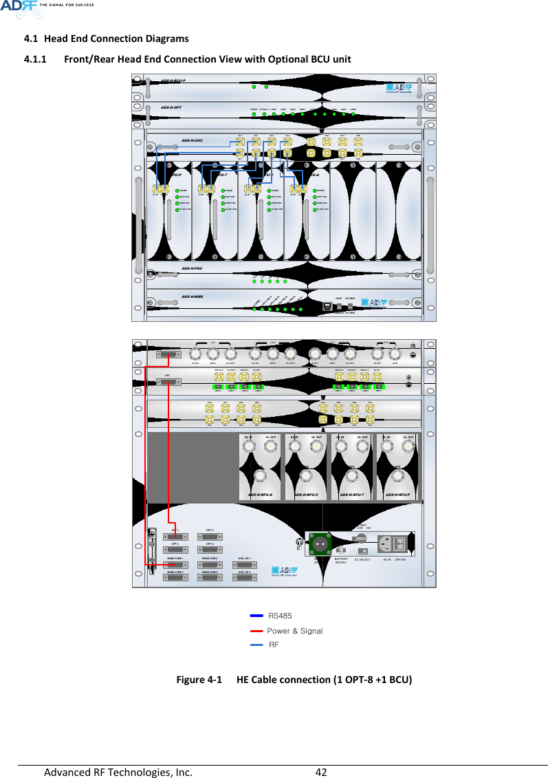
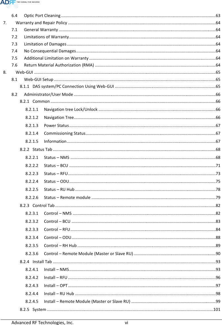
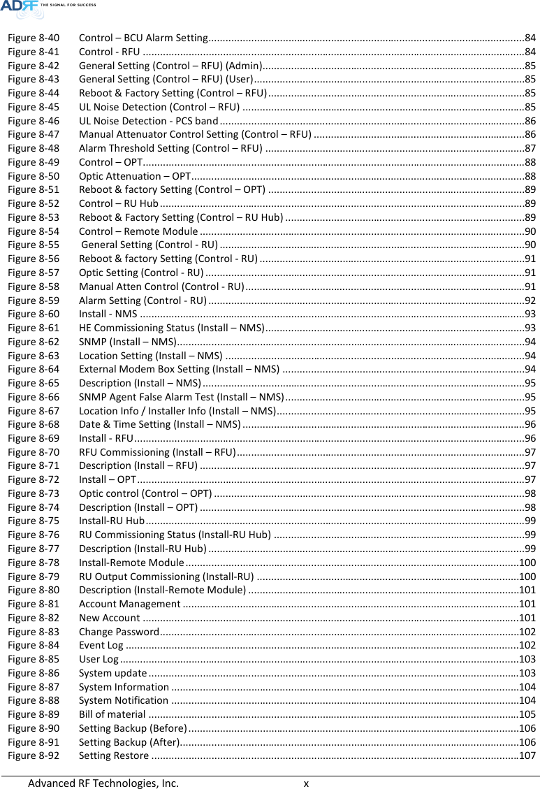
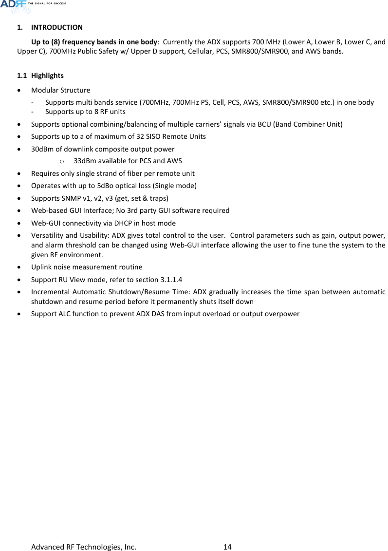
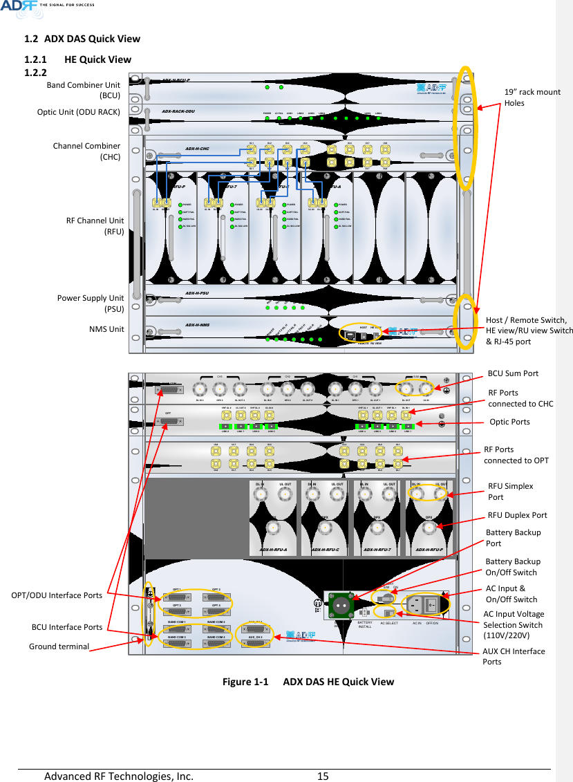
![Advanced RF Technologies, Inc. 25 3. ADX OVERVIEW 3.1 Head End The head end unit must always be connected to the Base Station using a direct cabled connection. This system has not been approved for use with a wireless connection via server antenna to the base station. Head end components include: ADX-H-NMS (Network Management System) ADX-H-CHC (Head End Channel Combiner) ADX-H-PSU (Head End Power Supply) Up to [4] ADX-H-BCU (Band Combiner Unit) Up to [8] ADX-H-RFU-x (RF Unit) Up to [4] ADX-H-RACK-ODU (Optical Unit rack) each ADX-H-RACK-ODU enables to have up to 2 ODU(ADX-H-ODU-4-X)s Specifications - Size: 19.0 x 14.6 x 12.2 inches (482 x 370 x 311 mm) - Weight: 83.7 lbs (38.0 Kg)@4 RFU, CHC-H, PSU and NMS - Power Consumption: 52W@4 RFU, 2 ODUs and NMS, 28W@1 RFU, 2 ODUs and NMS - Power Input: 110VAC or -48VDC(optional) - Supports the ADRF-BBU for external battery backup solution ADX-H-NMSPOWERSOFT FAIL-HSOFT FAIL-RHARD FAIL-HHARD FAIL-RLINK FAIL-HLINK FAIL-RHOST HE VIEWREMOTE RU VIEWADX-H-PSUPOWERCHG STSLOW BATTAC FAILDC FAILDL OUTUL INHARD FAILDL SIG LOWSOFT FAILPOWERADX-H-RFU-PDL OUTUL INHARD FAILDL SIG LOWSOFT FAILPOWERADX-H-RFU-7DL OUTUL INHARD FAILDL SIG LOWSOFT FAILPOWERADX-H-RFU-CDL OUTUL INHARD FAILDL SIG LOWSOFT FAILPOWERADX-H-RFU-AADX-H-CHCUL1 UL2 UL3 UL4DL1 DL2 DL3 DL4UL5 UL6 UL7 UL8DL5 DL6 DL7 DL8LD FAIL5-8 LINK5 LINK6 LINK7 LINK8LD FAIL1-4 LINK1 LINK2 LINK3 LINK4POWERADX-H-RACK-ODUSOFT FAILPOWERADX-H-BCU-P Figure 3-1 Head End Front View 메모 [Y4]: 추가 15/02/03](https://usermanual.wiki/ADRF-KOREA/ADX-R-SMR.User-Manual-Installaion-Manual-rev-Part1/User-Guide-2625928-Page-25.png)

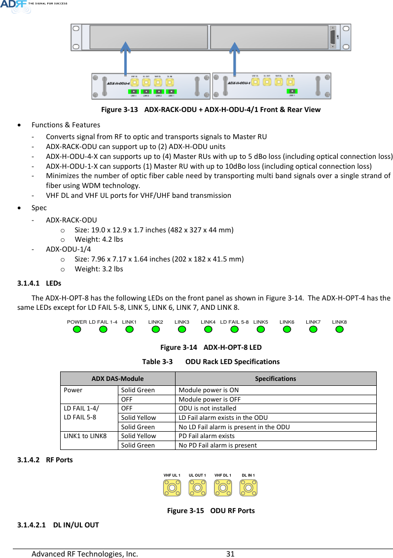
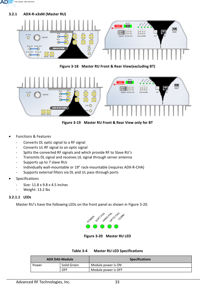
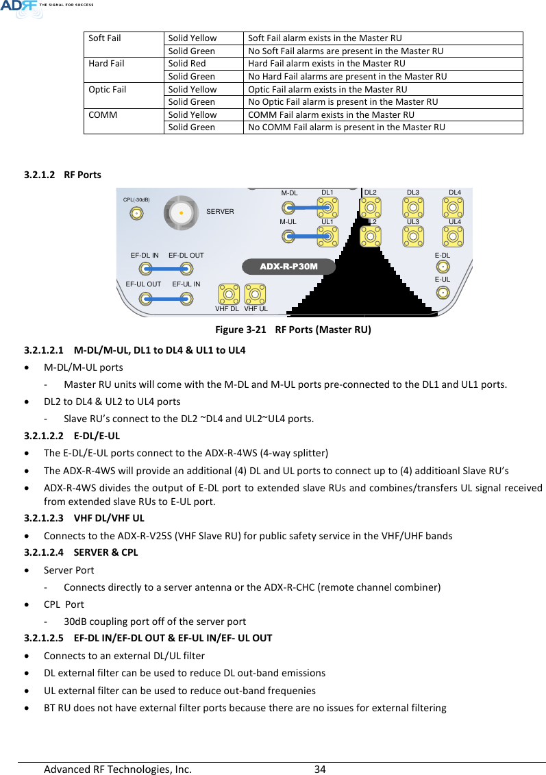
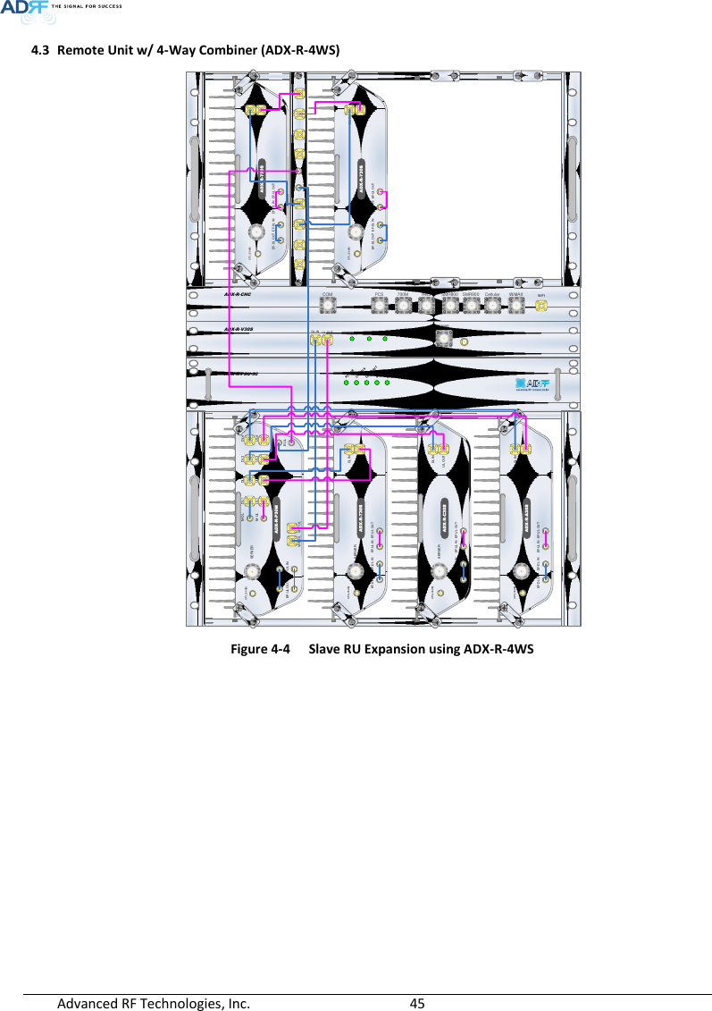
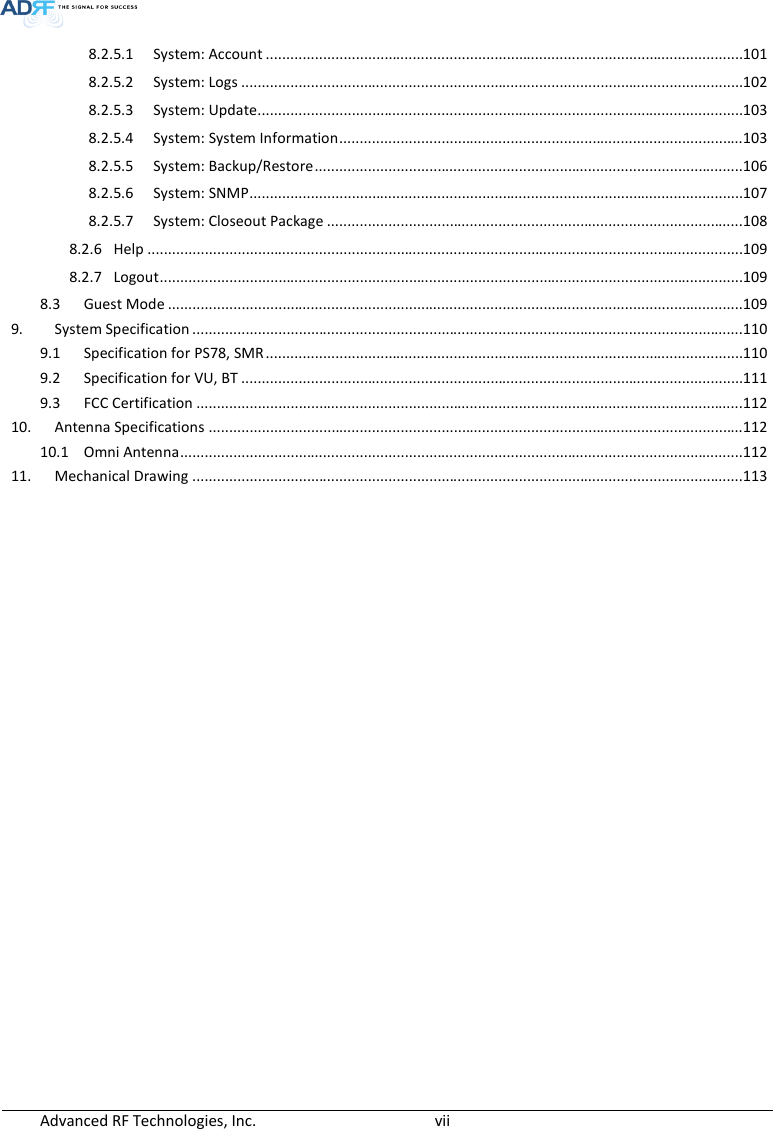
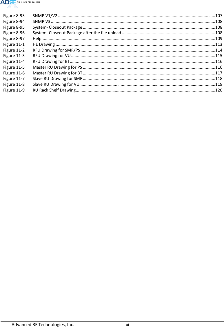
![Advanced RF Technologies, Inc. 32 The combined downlink signal received from ADX-H-CHC is transferred to the DL IN 1(or 2) at the back of OPT. The UL OUT port connects any of the ports on back of the ADX-H-CHC labeled UL 1 ~8. 3.1.4.2.2 VHF DL/VHF UL VHF DL/UHF UL ports are used to support Public Safety in the VHF & UHF frequency bands. VHF/UHF signals for Public Safety bypass the ADX-H-CHC and connect directly to the VHF DL/UHF UL ports of the ADX-H-OPT. 3.2 Remote Unit The remote unit is composed of a (1) Master RU and up to (7) Slave RU’s (ADX-R-4WS is required when connecting more than 3 Slave RU’s). A power source, either the ADX-R-ADP-30 (supports [1] Master/Slave RU) or the ADX-R-PSU-30 (supports up to [8] Master/Slave RU) is required. Specifications - Size: 19.0 x 12.9 x 10.5 inches - Weight: 61.0 lbs - Power Input: 110VAC or -48VDC (optional) ADX-R-730SDL INSERVERCPL(-30dB)UL OUTEF-DL OUT EF-DL IN EF-UL IN EF-UL OUTADX-R-C30SDL INSERVERCPL(-30dB)UL OUTEF-DL OUT EF-DL IN EF-UL IN EF-UL OUTADX-R-A30SDL INSERVERCPL(-30dB)UL OUTEF-DL OUT EF-DL IN EF-UL IN EF-UL OUTSERVERUL1 UL2 UL3 UL4ADX-R-P30MDL1 DL2 DL3 DL4M-DLM-ULCPL(-30dB)E-DLE-ULVHF DL VHF ULEF-DL IN EF-DL OUTEF-UL INEF-UL OUT Figure 3-16 RU Front View Figure 3-17 RU Rear View DC IN +27VON/OFFOUTPOWERSOFT FAILHARD FAILINDC IN +27VON/OFFOUTPOWERSOFT FAILHARD FAILINDC IN +27VON/OFFOUTPOWERSOFT FAILHARD FAILINPOWERSOFT FAILHARD FAILCOMMOPTIC FAILDC IN +27V PSU ALARM RS-485GUIOPTICON/OFFON1 2 3 4ADDRDANGER](https://usermanual.wiki/ADRF-KOREA/ADX-R-SMR.User-Manual-Installaion-Manual-rev-Part1/User-Guide-2625928-Page-32.png)