ADRF KOREA AXM7F-9543-X Repeater User Manual AXM700F 9543 ICS X MANUAL
ADRF KOREA, Inc. Repeater AXM700F 9543 ICS X MANUAL
AXM700F-9543-ICS-X_User Manual

Advanced RF Technologies, Inc.
ii
Information in this document is subject to change without notice.
Advanced RF Technologies, Inc. 1996-2013.
All rights reserved.
• Please send comments to:
E-Mail: info@adrftech.com
Phone: (818) 840-8131
(800) 313-9345
Fax: (818) 840-8138
• Address:
Advanced RF Technologies, Inc.
Attention: Technical Publications Department
3116 Vanowen St.
Burbank, CA 91505
USA
www.adrftech.com
Advanced RF Technologies, Inc.
iii
REVISION HISTORY
CHANGE LIST
Version Change list Contents
Version Author Descriptions Date
0.1
ADRF
Initial Release
11/02 2016

Advanced RF Technologies, Inc.
iv
TABLE OF CONTENTS
1. Introduction ...................................................................................................................................................... 10
1.1 Highlights ................................................................................................................................................... 10
1.2 Parts List..................................................................................................................................................... 11
1.3 Repeater Quick View ................................................................................................................................. 12
1.4 Warnings and Hazards ............................................................................................................................... 14
2. Overview ........................................................................................................................................................... 18
2.1 LED ............................................................................................................................................................. 18
2.2 Ethernet Port and Host/Remote Switch .................................................................................................... 18
2.2.1 Ethernet Ports .................................................................................................................................... 18
2.2.2 Host/Remote Switch ........................................................................................................................... 19
2.2.3 AC Power ............................................................................................................................................ 19
2.2.4 Back Up Battery Port .......................................................................................................................... 20
2.3 RF Ports ...................................................................................................................................................... 20
2.3.1 RF Ports............................................................................................................................................... 20
3. Alarms ............................................................................................................................................................... 21
3.1 Message Board Alarms and Notification ................................................................................................... 21
3.2 Alarms ........................................................................................................................................................ 22
4. Installation ........................................................................................................................................................ 23
4.1 Installation Procedures .............................................................................................................................. 23
4.1.1 Wall Mount Procedure ....................................................................................................................... 23
4.2 Grounding .................................................................................................................................................. 23
4.3 Antenna Separation/Isolation .................................................................................................................... 24
4.4 Line of Sight ............................................................................................................................................... 25
5. AXM700F-9543-ICS-X Web-GUI Setup .............................................................................................................. 26
5.1 Repeater/PC Connection Using Web-GUI .................................................................................................. 26
5.2 Status Tab .................................................................................................................................................. 27
5.2.1 Power & Gain ...................................................................................................................................... 27
5.2.2 Alarm .................................................................................................................................................. 27
5.2.3 Message Board ................................................................................................................................... 28
5.2.4 Install and Power Status ..................................................................................................................... 28
5.2.5 Repeater Info / Modem Info / Repeater Location / Technical Support / Installer Contact Info ........ 28
5.3 Control Tab ................................................................................................................................................ 30
5.3.1 General Setting ................................................................................................................................... 30
5.3.2 System ................................................................................................................................................ 31
5.3.3 SNMP Trap .......................................................................................................................................... 31
5.3.4 Manual Gain Control .......................................................................................................................... 31
5.3.5 ICS Control .......................................................................................................................................... 32

Advanced RF Technologies, Inc.
v
5.3.6 Alarm Setting ...................................................................................................................................... 32
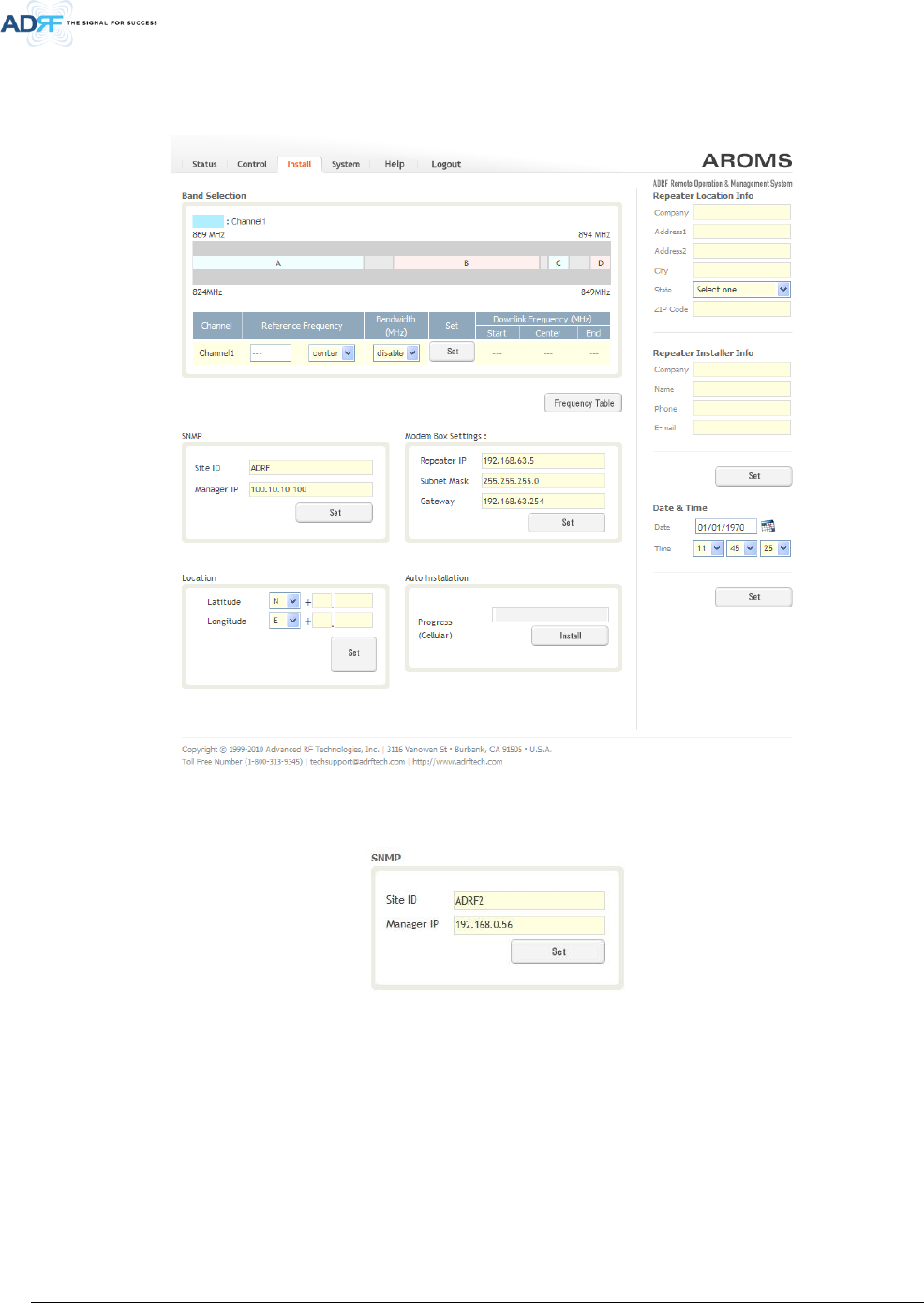
5.4 Install Tab ................................................................................................................................................... 33
5.4.1 Install .................................................................................................................................................. 33
5.4.2 SNMP .................................................................................................................................................. 33
5.4.3 Location .............................................................................................................................................. 33
5.4.4 Modem Box Settings .......................................................................................................................... 34
5.4.5 Auto Installation ................................................................................................................................. 34
5.4.6 Repeater Location Info / Repeater Installer Info ................................................................................ 35
5.4.7 Date & Time ........................................................................................................................................ 35
5.4.8 Band Selection .................................................................................................................................... 36
5.5 System ....................................................................................................................................................... 36
5.5.1 System: Account ................................................................................................................................. 36
5.5.1.1 System: Account- Account Management ................................................................................. 36
5.5.1.2 System: Account- New Account ................................................................................................ 36
5.5.1.3 System: Account- Administrator ............................................................................................... 37
5.5.1.4 System: Account- Change Password ......................................................................................... 37
5.5.2 System- Closeout Package .................................................................................................................. 38
5.5.3 System- User Log ................................................................................................................................ 38
5.5.4 System: Update .................................................................................................................................. 39
5.5.5 System- Backup .................................................................................................................................. 39
5.6 Help ............................................................................................................................................................ 39
5.7 Logout ........................................................................................................................................................ 40
6. Maintenance Guide for AXM700F-9543-ICS-X Repeater .................................................................................. 40
6.1 Periodic Inspection Checklist ..................................................................................................................... 40
6.2 Preventive Measures for Optimal Operation ............................................................................................ 40
6.2.1 Recommendations .............................................................................................................................. 40
6.2.2 Precautions ......................................................................................................................................... 40
7. Warranty and Repair Policy .............................................................................................................................. 40
7.1 General Warranty ...................................................................................................................................... 40
7.2 Limitations of Warranty ............................................................................................................................. 40
7.3 Limitation of Damages ............................................................................................................................... 40
7.4 No Consequential Damages ....................................................................................................................... 40
7.5 Additional Limitation on Warranty ............................................................................................................ 40
7.6 Return Material Authorization (RMA) ....................................................................................................... 41
8. Specifications .................................................................................................................................................... 41
8.1 Electrical Specifications ............................................................................................................................. 41
8.2 Mechanical Specifications.......................................................................................................................... 42
8.3 Power Specifications .................................................................................................................................. 42
8.4 Environment Specifications ....................................................................................................................... 42
8.5 Warranty & Certificates ............................................................................................................................. 42

Advanced RF Technologies, Inc.
vi
9. mechanical drawing .......................................................................................................................................... 43
10. Appendix ........................................................................................................................................................... 44
10.1 Shutdown Retry Logic ................................................................................................................................ 44

Advanced RF Technologies, Inc.
vii
FIGURES
Figure 1-1 AXM700F-9543-ICS-X Repeater Parts List ....................................................................................... 11
Figure 1-2 Repeater Quick View ....................................................................................................................... 13
Figure 2-1 LED panel ......................................................................................................................................... 18
Figure 2-2 Ethernet Port and Host/Remote Switch .......................................................................................... 18
Figure 2-3 AC Input Port ................................................................................................................................... 19
Figure 2-4 AC On/Off Switch and AC Selection ................................................................................................. 19
Figure 2-5 Battery Backup Port ......................................................................................................................... 20
Figure 2-6 RF ports ........................................................................................................................................... 20
Figure 4-1 Wall Mount ...................................................................................................................................... 23
Figure 4-2 Ground Cable Connection ............................................................................................................... 23
Figure 4-3 RF Repeater Oscillation ................................................................................................................... 24
Figure 4-4 Line of Sight to the eNode-B (or BTS) .............................................................................................. 25
Figure 5-1 Login page ....................................................................................................................................... 26
Figure 5-2 Status Tab ........................................................................................................................................ 27
Figure 5-3 Power & Gain Display ...................................................................................................................... 27
Figure 5-4 Alarm Display ................................................................................................................................... 28
Figure 5-5 Message Board ................................................................................................................................ 28
Figure 5-6 Install and Power Status .................................................................................................................. 28
Figure 5-7 Repeater Info / Modem Info / Repeater Location / Technical Support / Installer Contact Info ..... 29
Figure 5-8 Control page .................................................................................................................................... 30
Figure 5-9 General Setting ................................................................................................................................
30
Figure 5-10 System ............................................................................................................................................. 31
Figure 5-11 Pop-up message when Reboot button is pressed ........................................................................... 31
Figure 5-12 Pop-up message when Factory Setting button is pressed ............................................................... 31
Figure 5-13 SNMP Trap ....................................................................................................................................... 31
Figure 5-14 Manual Gain Control Setting ........................................................................................................... 31
Figure 5-15 ICS Control Setting ........................................................................................................................... 32
Figure 5-16 Alarm Threshold Setting .................................................................................................................. 32
Figure 5-17 Install page ...................................................................................................................................... 33
Figure 5-18 SNMP ............................................................................................................................................... 33
Figure 5-19 Location Setting ............................................................................................................................... 34
Figure 5-20 Modem Box Setting ......................................................................................................................... 34
Figure 5-21 Auto Installation .............................................................................................................................. 34
Figure 5-22 Repeater Location Info / Repeater Installer Info ............................................................................. 35
Figure 5-23 Date & Time Setting ........................................................................................................................ 35
Figure 5-24 Band Selection ................................................................................................................................. 36
Figure 5-25 System: Account- Account Management ........................................................................................ 36
Figure 5-26 System: Account- New Account ...................................................................................................... 36
Figure 5-27 System: Account- Administrator ..................................................................................................... 37
Figure 5-28 System: Account- Change Password ............................................................................................... 37
Figure 5-29 System- Closeout Package ............................................................................................................... 38
Figure 5-30 System- Closeout Package after the file upload .............................................................................. 38
Figure 5-31 System – User Log ........................................................................................................................... 38
Figure 5-32 System – Update ............................................................................................................................. 39
Figure 5-33 Pop-up message after System update is complete ......................................................................... 39
Figure 5-34 System Backup ................................................................................................................................. 39
Figure 5-35 Help ................................................................................................................................................. 39
Figure 9-1 AXM700F-9543-ICS-X Mechanical Drawing ..................................................................................... 43

Advanced RF Technologies, Inc.
viii
TABLES
Table 1-1 Parts List .......................................................................................................................................... 11
Table 2-1 LED Specifications ............................................................................................................................ 18
Table 3-1 Message Board Alarms and Notification ......................................................................................... 21
Table 3-2 Alarms Threshold ............................................................................................................................. 22
Table 8-1 Electrical Specifications ................................................................................................................... 41
Table 8-2 Mechanical Specifications ............................................................................................................... 42
Table 8-3 Power Specifications ....................................................................................................................... 42
Table 8-4 Environment Specifications ............................................................................................................. 42
Table 8-5 Warranty & Certificates ................................................................................................................... 42

Advanced RF Technologies, Inc.
9
Terms and Abbreviations
The following is a list of abbreviations and terms used throughout this document.
Abbreviation/Term Definition
AGC Automatic Gain Control
ALC Automatic Level Control
AROMS ADRF’ Repeater Operation and Management System
BDA Bi-Directional Amplifier
BTS Base Transceiver Station
CDMA Code Division Multiple Access
CFR Crest Factor Reduction
CP Cyclic Prefix
CW Continuous Wave (un-modulated signal)
DAS Distributed Antenna System
DL Downlink
eNode-B Evolved Node B which is the element in E-UTRA of LTE that is the evolution of the
element Node B in UTRA of UMTS
HPA High Power Amplifier
HW Hardware
ICS Interference Cancellation System
ILC Interference Level Control
IF Intermediate Frequency
LNA Low Noise Amplifier
LTE Long Term Evolution
MS Mobile Station
OFDM Orthogonal Frequency-Division Multiplexing
OFDMA Orthogonal Frequency-Division Multiple Access
PAR (PAPR) Peak to Average Power Ratio (Crest Factor)
PLL Phase Locked Loop
PSU Power Supply Unit
QAM Quadrature Amplitude Modulation
QPSK Quadrature Phase Shit Keying
RB Resource Block
RF Radio Frequency
SC-FDMA Single Carrier-Frequency Division Multiple Access
SQE Signal Quality Estimate
SW Software
eUE LTE User Equipment (LTE Mobile Station)
UL Uplink
VSWR Voltage Standing Wave Ratio

Advanced RF Technologies, Inc.
10
1. INTRODUCTION
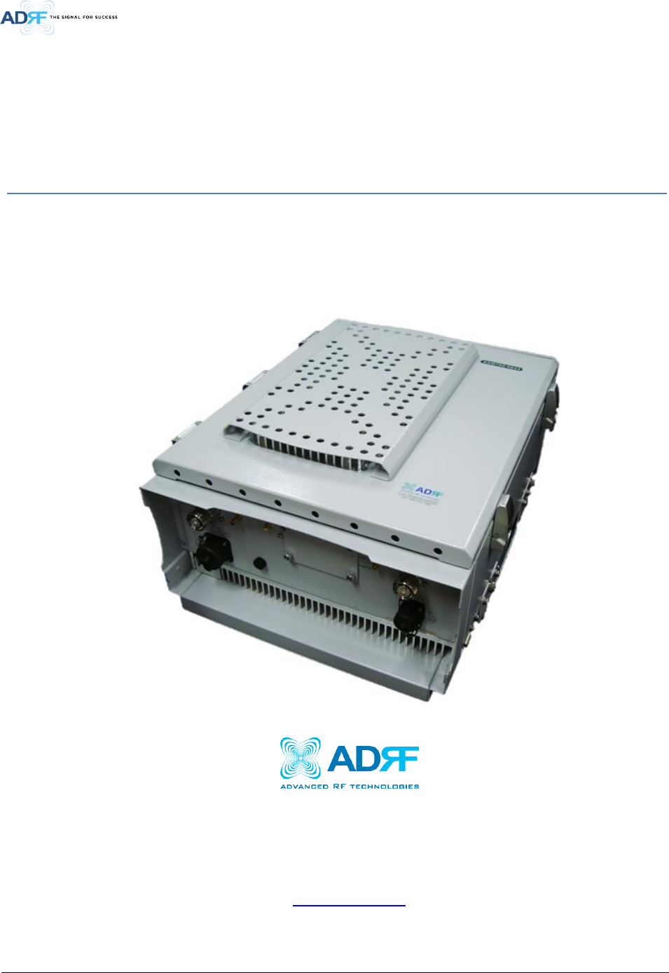
The AXM700F-9543-ICS-X is an over-the-air high power repeater.
1.1 Highlights
• Active ICS (Interference Cancellation System)
• Band Selectable
• Digital filtering with sharp roll-off (>50dBc @ ± 1 MHz from sub-band edge)
• Remote monitoring and control capability using our Web-based GUI
• 95 dB of max gain and 43/30dBm (DL/UL) Composite power
• LED panel provide signal strength and alarm status
• Support optional internal modem box for remote access and alarming
• Configurable network setting in order to interface with 3rd party external modem boxes
• Adjustable AGC Output Power Level
• Supports Network Management Monitoring System via SNMP
• Incremental Automatic Shutdown/Resumption Time: AXM700F-9543-ICS-X gradually increases the time span
between automatic shutdown and resumption before it permanently shuts itself down
• Versatility and Usability: AXM700F-9543-ICS-X gives total control to the user. Most of the control parameters,
e.g., gain, output power, alarm threshold, etc. can be changed using the Web-GUI so that the user can adjust
the system perfectly to the given RF environment
• Web-GUI connectivity via DHCP
• Supports DHCP; No 3rd party GUI software required
• Automated installation
• Direct ray cover on heat-sink to prevent direct light (Front door)
• Membrane vent to prevent moisture by condensation
Advanced RF Technologies, Inc.
11
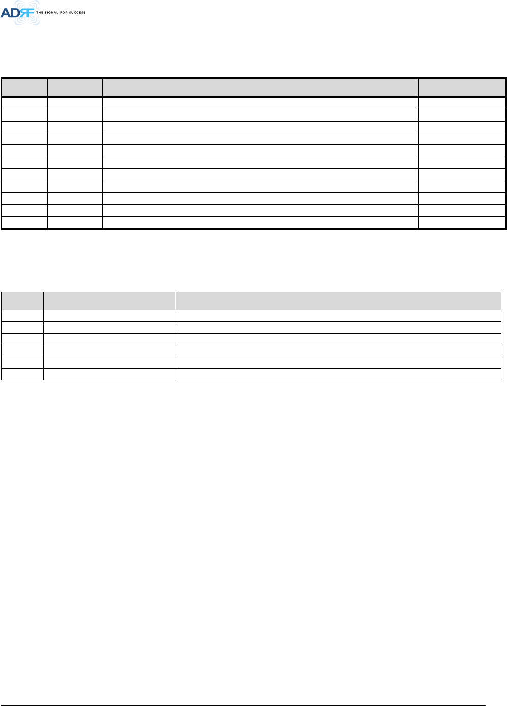
1.2 Parts List
Table 1-1 Parts List
Label Quantity Description
AXM700F-9543-ICS-X
A
1
AXM700F-9543-ICS-X
B
1
Wall Mount Bracket
C
1
Mounting Bracket Template
D
1
AC Power Cable
E
1
Ethernet Cable (Crossover)
F
6
Anchor Bolt
G
1
Ground Cable
H
1
Documentation CD*
Optional AXM700F-9543-ICS-X Modem Package
I
1
Modem
J
1
Modem Power Cable
K
1
Ethernet Cable (Crossover)
L
1
Modem Antenna
Figure 1-1 AXM700F-9543-ICS-X Repeater Parts List
* CD includes: User Manual, Quick-Start Guide, and Troubleshooting Guide
D
E
F
B
G
H
A
I
J
K
L
C
Advanced RF Technologies, Inc.
12
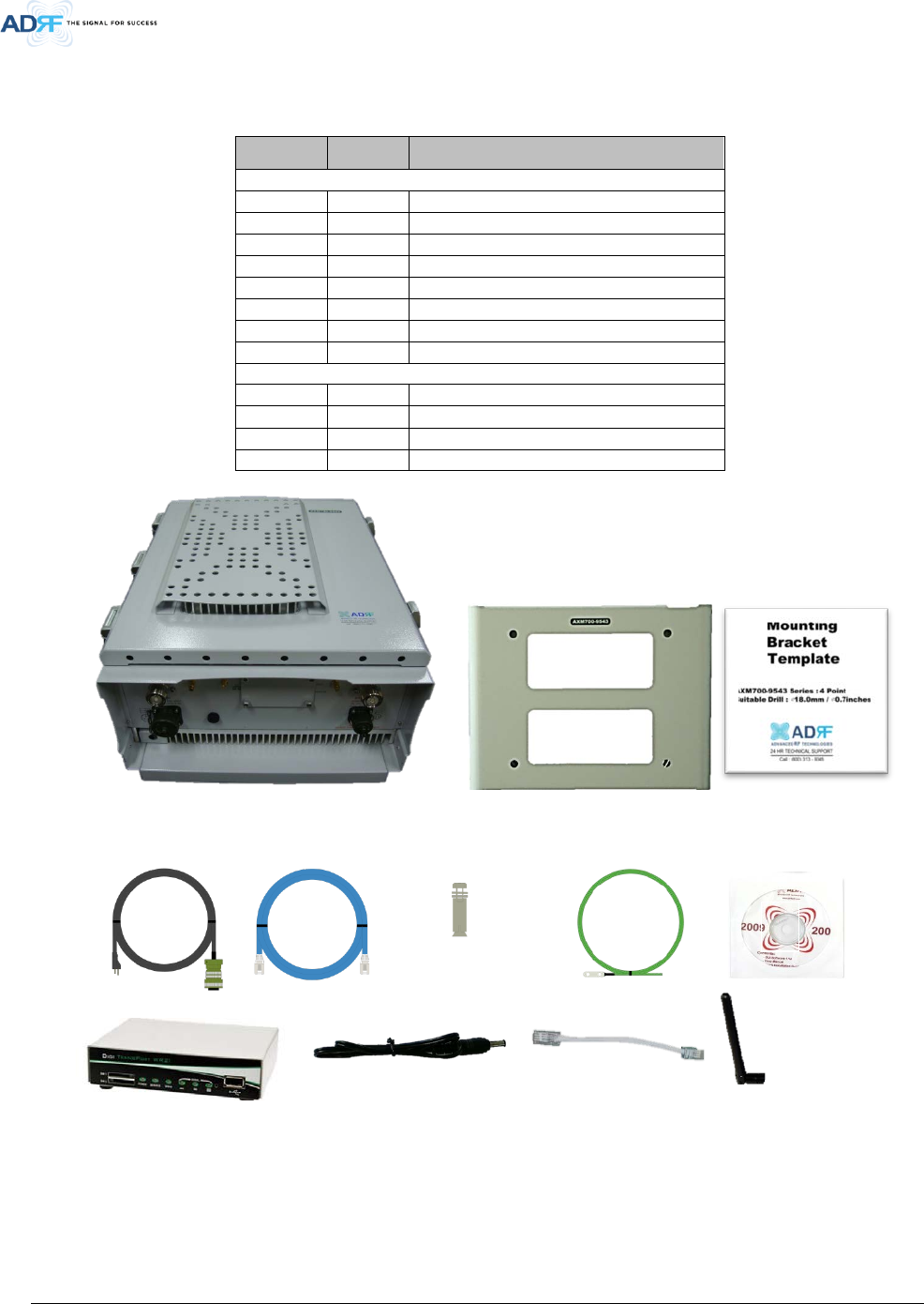
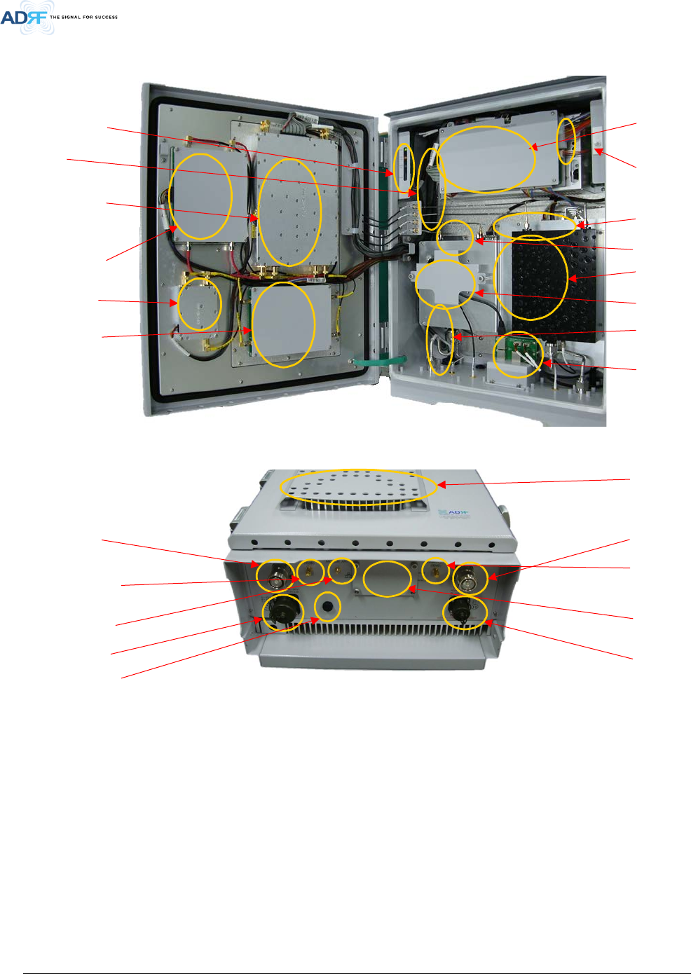
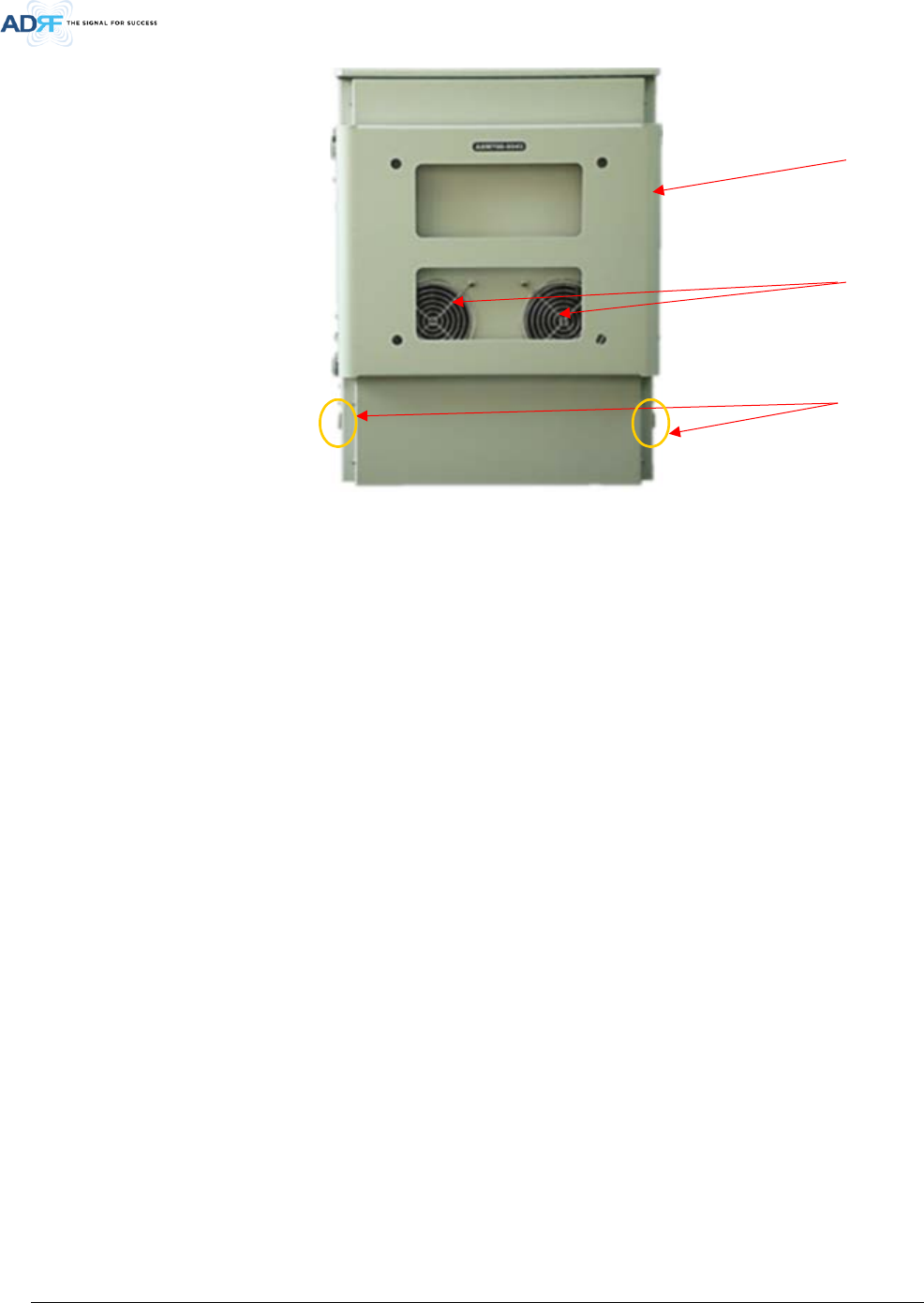
1.3 Repeater Quick View
LED indicator
Controller
UDC Module
PSU
Ethernet port
(RJ
-45)
ADRF-BBU
B
attery port
Donor port
(DIN Female)
Modem antenna
port
AC Input port
Membrane Vent
Door Switch
DL HPA
UL HPA
Server Duplexer
Donor Duplexer
Optional
Modem
DSP Module
(ICS)
Ethernet
Interface Board
Direct Ray Cover
Server port (DIN
Female)
Sever CPL (DL
Output Monitor
port,
-30dB)
Donor CPL (UL
Output Monitor
port,
-30dB)
DSP Module
(SDR)
UL SUB
Module
Advanced RF Technologies, Inc.
13
Figure 1-2 Repeater Quick View
Wall-mount
Bracket
Fan
Ground
terminal
Advanced RF Technologies, Inc.
14
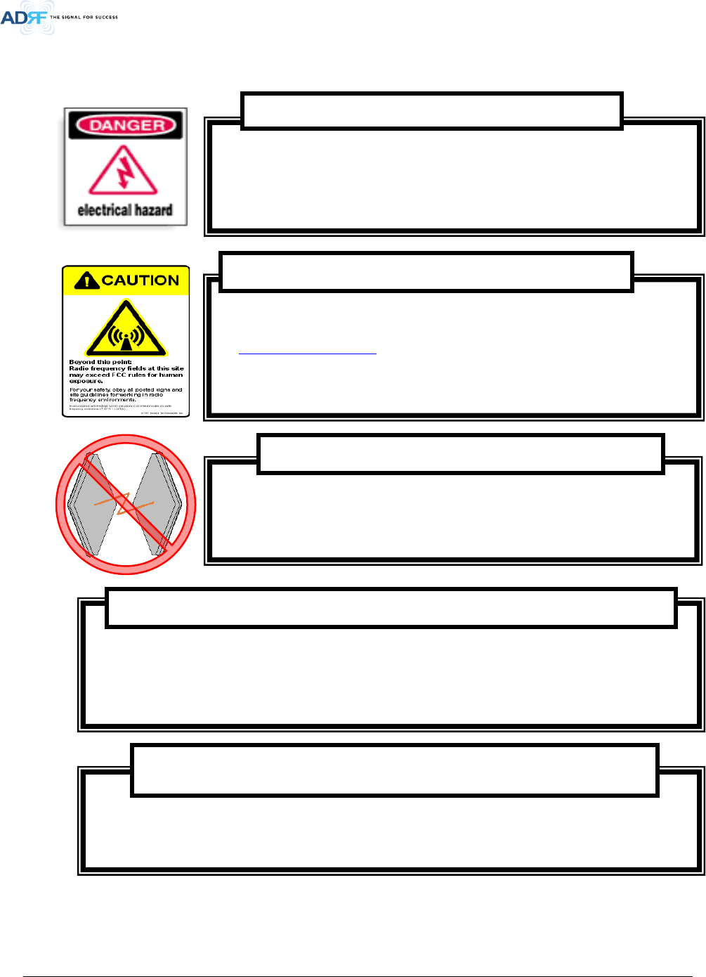
1.4 Warnings and Hazards
Opening the AXM700F-9543-ICS-X could result in electric shock and may
cause severe injury.
Working with the repeater while in operation, may expose the technician to RF
electromagnetic fields that exceed FCC rules for human exposure. Visit the FCC website
at www.fcc.gov/oet/rfsafety to learn more about the effects of exposure to RF
electromagnetic fields.
WARNING! EXPOSURE TO RF
Operating the AXM700F-9543-ICS-X with antennas in very close proximity facing
each other could lead to severe damage to the repeater.
WARNING! DAMAGE TO REPEATER
Actual separation distance is determined upon gain of antenna used.
Please maintain a minimum safe distance of at least 300 cm while operating near the donor and the server
antennas. Also, the donor antenna needs to be mounted outdoors on a permanent structure.
RF EXPOSURE & ANTENNA PLACEMENT Guidelines
Opening or tampering the AXM700F-9543-ICS-X will void all warranties.
WARRANTY
WARNING!
ELECTRIC
SHOCK
Advanced RF Technologies, Inc.
15
Lithium Battery: CAUTION. RISK OF EXPLOSION IF BATTERY IS REPLACED BY INCORRECT
TYPE. DISPOSE OF USED BATTERIES ACCORDING TO INSTRUCTIONS.
Ethernet Instructions: This equipment is for indoor use only. All cabling should be limited
to inside the building.
Preclude indications that Home/ personal use are prohibited.
Use of unauthorized antennas, cables, and/or coupling devices not conforming with
ERP/EIRP is prohibited.
NOTE: This equipment has been tested and found to comply with the limits for a Class A
digital device, pursuant to part 15 of the FCC Rules. These limits are designed to provide
reasonable protection against harmful interference when the equipment is operated in a
commercial environment. This equipment generates, uses, and can radiate radio frequency
energy and, if not installed and used in accordance with the instruction manual, may cause
harmful interference to radio communications. Operation of this equipment in a residential
area is likely to cause harmful interference in which case the user will be required to correct
the interference at their own expense.
FCC Part 15 Class A
Advanced RF Technologies, Inc.
16
◈LABEL WARNING◈
Antennas must be installed in accordance with FCC 27.50 and SRSP 518. With 17dBi gain antennas the
height of the antenna above average terrain (HAAT) must not exceed 1106m. For different gain
antennas refer to the relevant rules.
FCC Part 27.50
Double Pole/Neutral Fusing.
CAUTION
Advanced RF Technologies, Inc.
17
FCC RF Radiation Exposure Statement:
This equipment complies with FCC RF radiation exposure limits set forth for an uncontrolled
environment. This equipment should be installed and operated with a minimum distance of
300cm between the radiator and your body. This transmitter must not be co-located or operating
in conjunction with any other antenna or transmitter.
Regulatory Warning Statement
This 3.5dB back off is only required when multiple carriers are present in the pass-band.
Power Reduction Warning Statement
Advanced RF Technologies, Inc.
18
2. OVERVIEW
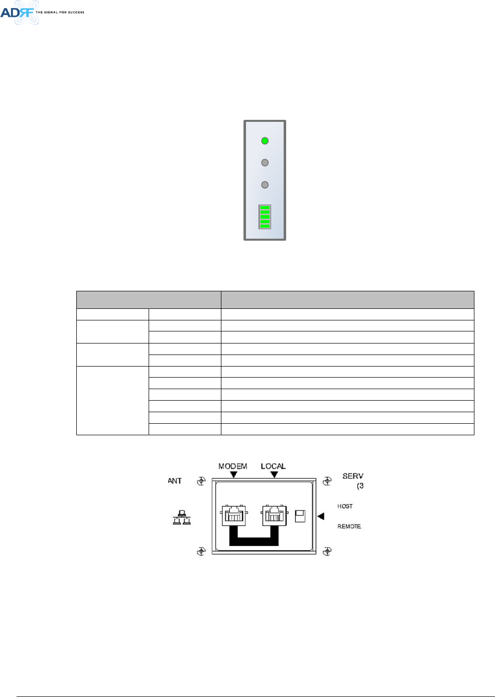
2.1 LED
AXM700F-9543-ICS-X has LEDs in the upper left corner as shown in figure below.
POWER
SOFT FAIL
HARD FAIL
RSSI
Figure 2-1 LED panel
Table 2-1 LED Specifications
LED Indicator Specifications
Power
Solid Green
System power is ON
Soft Fail
Solid Yellow
Soft Fail alarm exist in the system
OFF
No Soft Fail alarm are present in the system
Hard Fail
Solid Red
Hard Fail alarm exist in the system
OFF
No Hard Fail alarms are present in the system
RSSI
Input < -85dBm
Zero (0) bar On
Input < -75dBm
One (1) bar On
Input < -65dBm
Two (2) bars On
Input < -55dBm
Three (3) bars On
Input < -45dBm
Four (4) bars On
Input >= -45dBm
Five (5) bars On
2.2 Ethernet Port and Host/Remote Switch
Figure 2-2 Ethernet Port and Host/Remote Switch
2.2.1 Ethernet Ports
• Modem – The Modem port is to only be used when the optional internal modem box (Digi Transport-WR21) is
used with the repeater. This port directly connects to the Ethernet port of the internal modem box. If a Digi
Transport WR-21 is being used with the repeater, use the included RJ-45 jumper cable to connect the Local
and Modem ports together and then flip the Host/Remote switch to the Remote position.
Advanced RF Technologies, Inc.
19
• Local – The Local port can be used to communicate directly with the AXM700F-9543-ICS-X using a RJ-45
crossover cable or can also be used to connect the AXM700F-9543-ICS-X to an external modem box or the
optional internal Digi Transport WR-21.
2.2.2 Host/Remote Switch
The Host/Remote Switch allows the user to switch the default Repeater IP, Subnet Mask, and Gateway of the
LOCAL port of the repeater to an alternative setup. These settings can be adjusted by logging into the repeater in
HOST mode and configuring the settings under the Modem Box Setting section on the Install Page (section 5.4.4).
Once the settings are set, flipping the switch to the REMOTE position will reboot the repeater with the new
alternate settings. Please note that when the repeater is set to the REMOTE position, DHCP is disabled and the
repeater will not automatically assign an IP address to any device that connects directly to the repeater.
• Host IP: 192.168.63.1 (Fixed IP, unable to modify this IP address)
• Remote IP: 192.168.63.5 (Default IP, but can be modified in Host mode)
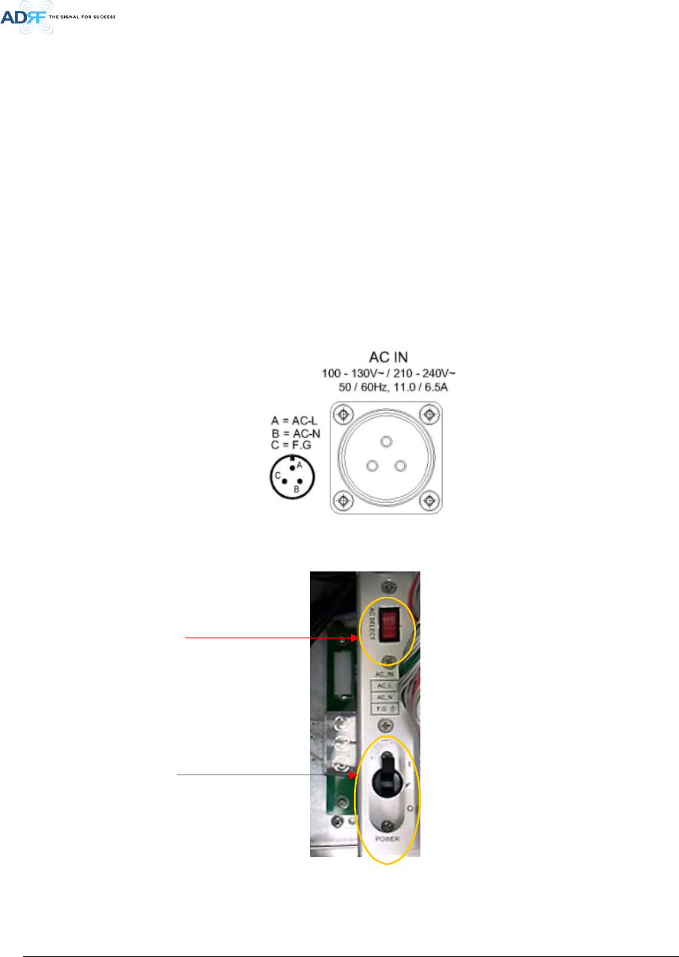
2.2.3 AC Power
Figure 2-3 AC Input Port
AC port is located at bottom of system.
Figure 2-4 AC On/Off Switch and AC Selection
The AC Power on/off switch and AC selection switch are located at left of PSU. The AXM700F-9543-ICS-X PSU
can operate at 110V AC and 220V AC. The user should verify that the AC input voltage selection switch is set to the
correct voltage before powering on the AXM700F-9543-ICS-X.
AC Selection switch
AC On/Off switch
Advanced RF Technologies, Inc.
20
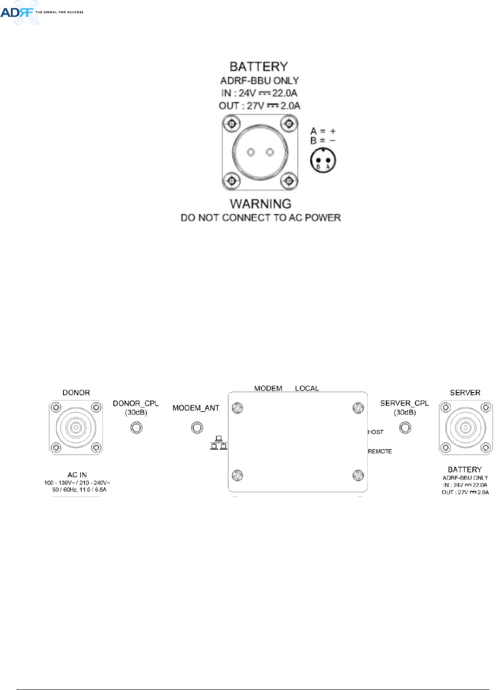
2.2.4 Back Up Battery Port
Figure 2-5 Battery Backup Port
The AXM700F-9543-ICS-X can be connected to an ADRF-BBU (ADRF Battery Backup Unit) to provide power
during a power failure. If an ADRF-BBU is utilized, connect the ADRF-BBU to the AXM700F-9543-ICS-X via the
external battery port.
(WARNING: The circuit breaker switch on the ADRF-BBU must be set to OFF before connecting the ADRF-BBU
to the AXM700F-9543-ICS-X to prevent damage to the repeater or the ADRF-BBU and personal injury.)
Note: Please contact ADRF Technical Support for assistance if you are unfamiliar with the installation
procedure of the battery box.
2.3 RF Ports
Figure 2-6 RF ports
2.3.1 RF Ports
• DONOR – DIN female which is used to connect the donor antenna
• DONOR_CPL (30dB) – SMA female 30 dB coupling port which is used to monitor the amplified UL signal
• MODEM_ANT – SMA female port which is used to provide RF signal to the optional internal modem box
• SERVER_CPL (30dB) – SMA female 30 dB coupling port which is used to monitor the amplified DL signal
• SERVER – DIN female which is used to connect the server antenna
Advanced RF Technologies, Inc.
21
3. ALARMS
3.1 Message Board Alarms and Notification
Table 3-1 Message Board Alarms and Notification
Parameters
Remark
AC Fail
Power supply is not operating within specs
DC Fail
Power supply is not operating within specs
Fan[1/2] Fail
System has detected an issue with the fan1 and fan2
Temperature
Module is above the normal operating temperature
Current
Power supply is not operating within specs
System Halt
System is in a shutdown state due to a hard fail alarm
DSP Fault
System has detected an issue with the internal DSP
OSC
Oscillation detected
DL Signal not detected
DL signal is below the specified level
DL Signal Low
DL signal is below the specified level
Input Overload
Incoming in-band DL or UL signal is too strong
Out of band Overload
Incoming out-band DL or UL signal is too strong
Synthesizer Lock Fail
Issue with internal PLL
DL RF Power
Input + gain does not match the output level (above delta of 6 dB)
Overpower
Output level is above the max output levels
VSWR
Power is being reflected back to the repeater
Heartbeat
Heartbeat
Reboot
Reboot
Factory setting
Factory setting
Door
Door alarm set/clear.
Advanced RF Technologies, Inc.
22
3.2 Alarms
Table 3-2 Alarms Threshold
Parameters Remark
AC Fail
Power supply is not operating within specs. (4 seconds)
DC Fail
Power supply is not operating within specs. (4 seconds)
Fan1, Fan2 Fail
System has detected an issue with each fan. (4 seconds)
Temperature
Module is above the normal operating temperature. (4 seconds)
Over Temperature [ Soft: 80~87 C, Hard: Above 87 C]
Current
Power supply is not operating within specs. (4 Second)
Over Current [ Hard: Above 20A]
System Halt System is in a shutdown state due to a hard fail alarm. (10 times)
DSP Fault
System has detected an issue with the internal DSP chip. (Cannot
communication with DSP)
OSC
Oscillation detected. Alarm is only present when one-time oscillation
check is performed.
DL Signal not detected DL signal is below the specified level. (default: -90dBm, 4 seconds)
DL Signal Low DL signal is below the specified level. (default: -85dBm, 4 seconds)
Input Overload
Input signal is above the threshold. (4 seconds)
(Soft: DL -10dBm/UL -12dBm, Hard: DL -8dBm/UL -10dBm)
Out of band Overload
Out of band signal is above the threshold. (4 seconds)
(Soft: DL -10dBm/UL -12dBm, Hard: DL -8dBm/UL -10dBm)
Synthesizer Lock Fail
Issue with internal PLL(4 seconds)
DL RF Power
Input + gain does not match the output level
(default delta of 6 dB)
Overpower
Output level is above the max output levels
AGC On case(Soft: AGC Level+ 1~2dB, Hard: AGC Level + >2dB)
AGC Off case(Soft: max output level+ 1~2dB, Hard: max output level +
>2dB)
VSWR
Power is being reflected back to the repeater. Threshold = output
power
- 8dB. For example, if the repeater is outputting 24dBm, then if
the system detects 16dBm of return power, then the VSWR will be
triggered.(Triggered in case of over +15dBm output power)
Door Door alarm set : Door open
Door alarm clear : Door close
Advanced RF Technologies, Inc.
23
4. INSTALLATION
4.1 Installation Procedures
4.1.1 Wall Mount Procedure
• Verify that the AXM700F-9543-ICS-X and mounting hole are in good condition
• Place the AXM700F-9543-ICS-X mounting bracket template up against the wall and mark of mount holes
• Mount the AXM700F-9543-ICS-X to wall use the six (6) mounting hole on the wall mount bracket
• Connect the GND cable
• Connect the Antenna cable
• Connect the Power cable
Figure 4-1 Wall Mount
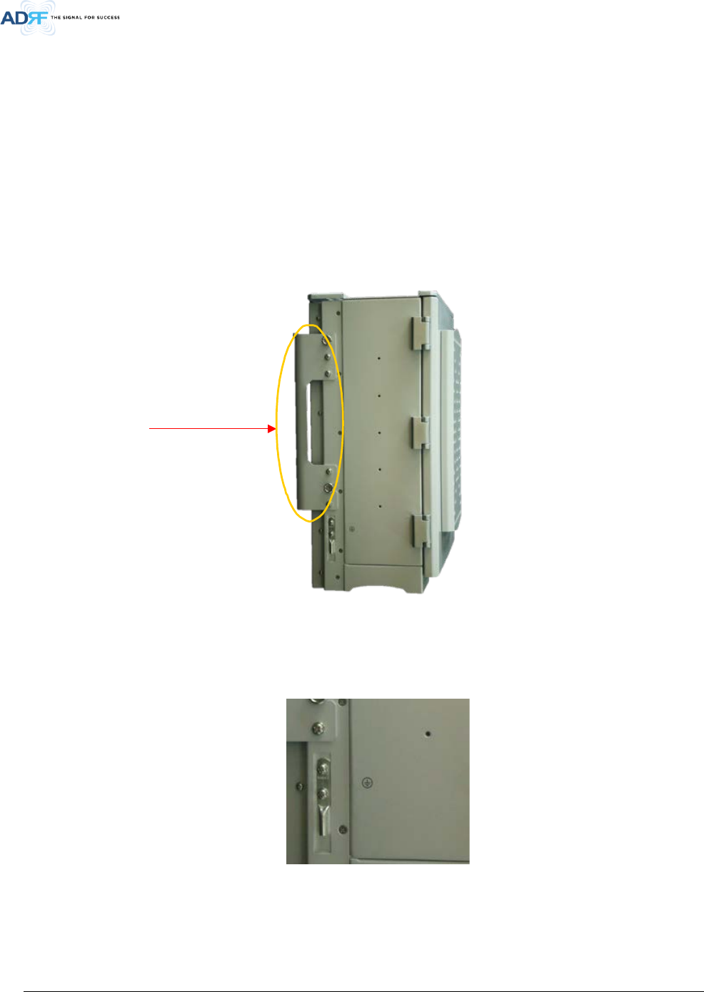
4.2 Grounding
Install the ground cable that is included in the package at the back of the repeater as show in the figure below.
Figure 4-2 Ground Cable Connection
• Round ground terminals are located on the side of the repeater.
Mount bracket
Advanced RF Technologies, Inc.
24
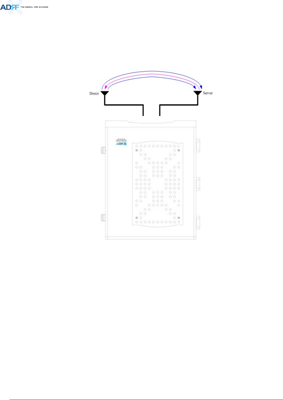
4.3 Antenna Separation/Isolation
Separation between the antennas is necessary to prevent oscillation. Oscillation occurs when the signal
entering the system continually reenters, due to the lack of separation between the donor and server antennas. In
other words, the signal is being fed back into the system. This creates a constant amplification of the same signal.
As a result, the noise level rises above the signal level.
Figure 4-3 RF Repeater Oscillation
To prevent feedback, the donor and server antennas must be separated by an appropriate distance to provide
sufficient isolation. Isolation can be attained by separating antennas at a sufficient distance so that the output of
one antenna does not reach the input of the other. This distance is dependent on the gain of the repeater.
With ICS mode, the recommended isolation value is 5dB greater than the maximum gain of the repeater. For
example, if the gain of the repeater is 50 dB, then an isolation of 55dB or greater is required. In the same manner,
because the AXM700F-9543-ICS-X has a maximum gain of 95dB in case of AXM700F-9543-ICS-X, it requires
isolation of at least 100dB.
With SDR mode, the recommended isolation value is 20dB greater than the maximum gain of the repeater. For
example, if the gain of the repeater is 50 dB, then an isolation of 70dB or greater is required. In the same manner,
because the AXM700F-9543-ICS-X has a maximum gain of 95dB in case of AXM700F-9543-ICS-X, it requires
isolation of at least 115dB.
WARNING: Inserting a CW signal into the AXM700F-9543-ICS-X when ICS is enabled will cause the system to
generate a false alarm. The false alarm will cause the system to go into a shutdown state. If a CW signal needs to
be injected into the repeater for testing purposes, the ICS routine must be turned off.
Advanced RF Technologies, Inc.
25
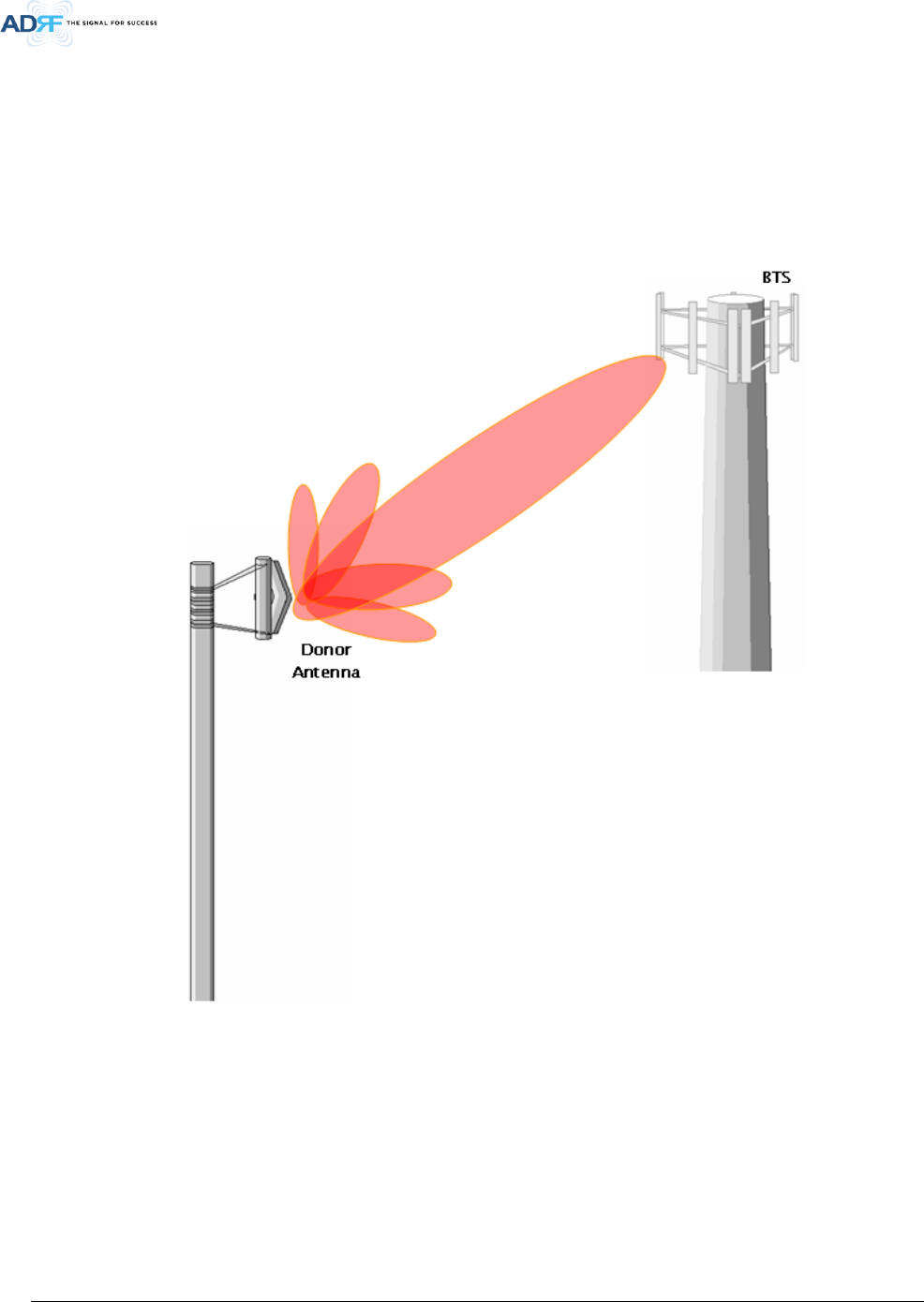
4.4 Line of Sight
The donor antenna which points towards the eNode-B (or BTS) typically has a narrow beam antenna pattern.
As a result, a slight deviation away from the direction of the eNode-B (or BTS) can lead to less than optimal results.
In addition, obstacles between the repeater and the eNode-B (or BTS) may impair the repeater from obtaining any
eNode-B (or BTS) signal. As a result, the repeater cannot transmit signal to the coverage area. Therefore, a direct
line of sight to the eNode-B (or BTS) for the donor antenna is vital to the operation of a repeater. For the same
reason, placing the server antenna in direct line of sight of the coverage area is also necessary.
Figure 4-4 Line of Sight to the eNode-B (or BTS)
Advanced RF Technologies, Inc.
26
5. AXM700F-9543-ICS-X WEB-GUI SETUP
The Web-GUI allows the user to communicate with the repeater either locally or remotely. To connect to the
repeater locally, you will need a laptop with an Ethernet port and a RJ-45 crossover cable. To connect to the
repeater remotely, you will need to have an active internet connection and the repeater must have either an
internal modem or an external modem box connected to the repeater.
5.1 Repeater/PC Connection Using Web-GUI
• Verify that your Local Area Network Connection is set to obtain an IP address automatically under the Internet
Protocol (TCP/IP) properties
- If you are connecting to the unit remotely (use of a modem), then skip steps above.
• Connect the RJ-45 crossover cable between the laptop’s Ethernet port and the repeater’s Ethernet port
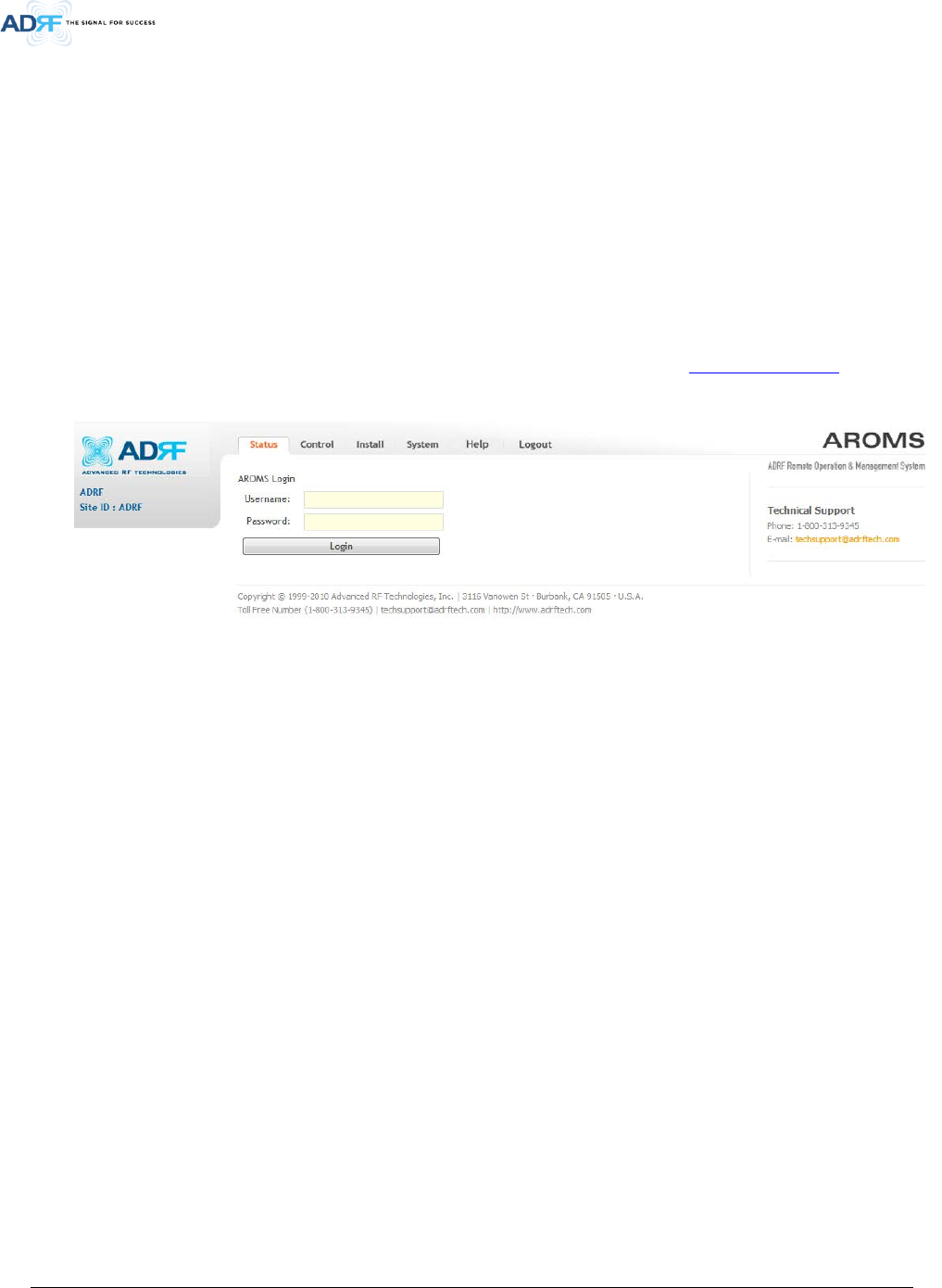
• Launch an Internet Browser
• Type the following IP address into the address bar of Microsoft Internet Explorer: http://192.168.63.1
- If you are connecting to the unit remotely, then type the IP address of the modem to connect to the unit
• The following login screen will appear:
Figure 5-1 Login page
If you are not the Administrator, please type in your assigned username & password which you should have
received from the Administrator.
The default username and password for the General User is adrf & adrf, respectively.
The default Administrator login is admin & admin, respectively.
Advanced RF Technologies, Inc.
27
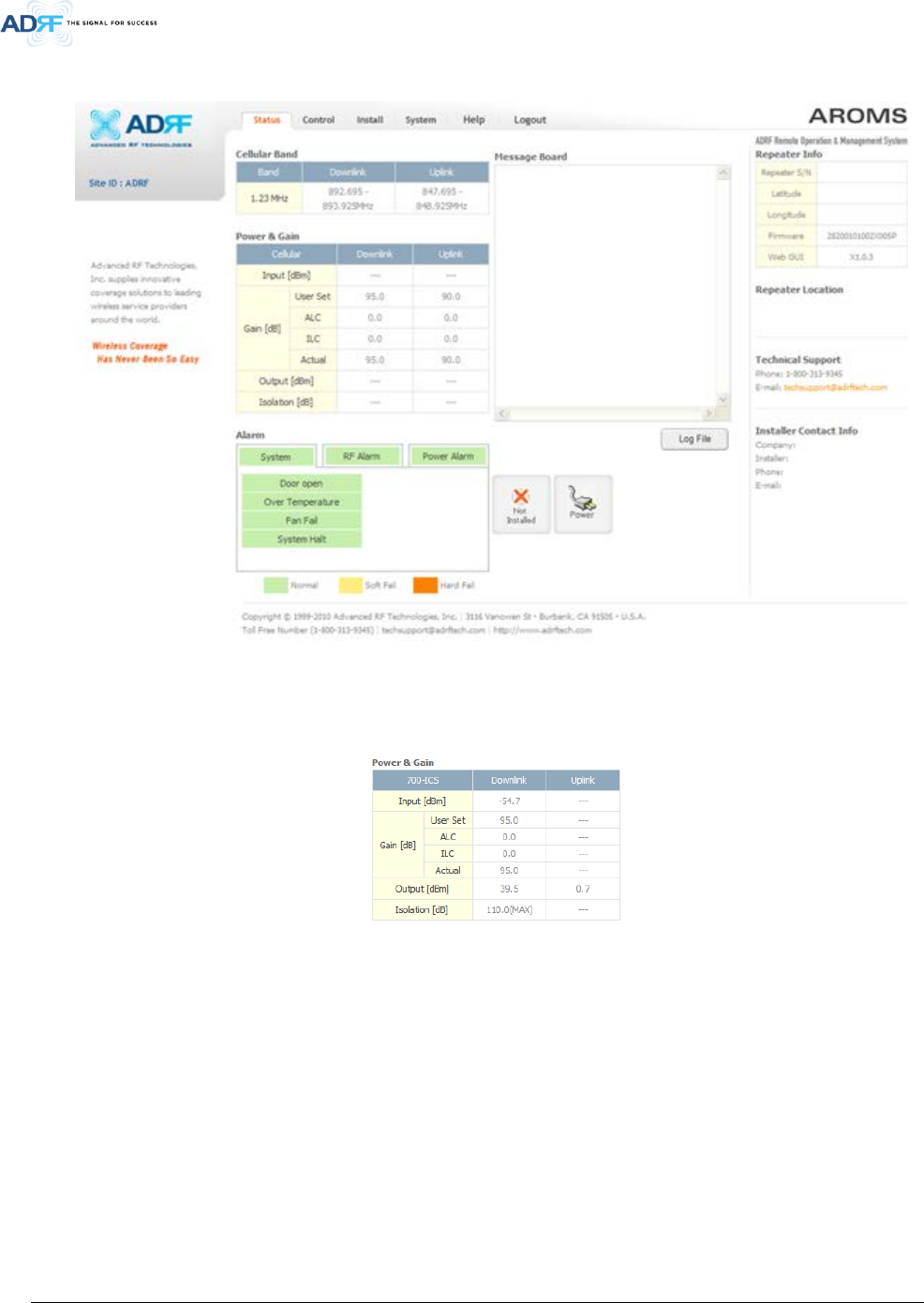
5.2 Status Tab
Figure 5-2 Status Tab
5.2.1 Power & Gain
This section displays the Input, Gain, and Output for both downlink and uplink.
Figure 5-3 Power & Gain Display
• Input [dBm] – Displays the in-band Downlink/Uplink signal level. The system will display “--.-“when the input
level is < -90 dBm.
• Gain [dB]
- User Set: Displays the amount of gain that user set.
- ALC: Displays the amount of gain that is attenuated by ALC function.
- ILC: Displays the amount of gain that is attenuated by ILC function.
- Actual: Displays the actual amount of gain that is currently in use.
• Output [dB] – Displays the Downlink/Uplink output power levels. The system will display --.-“, when the
output level is < +5 dBm.
• Isolation [dB] – Displays the measured isolation value. The value inside of the parenthesis is the “actual gain -
measured isolation value”. When the “actual gain – measured isolation value” is less than -15dB, then “MAX”
will be displayed.
5.2.2 Alarm
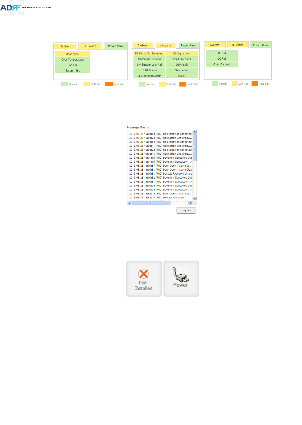
Advanced RF Technologies, Inc.
28
This section displays the alarm status for System alarms, RF Alarms, and Power alarms. If an alarm is present
in the system, then the color of the alarm tab will change according to the type of failure.
Figure 5-4 Alarm Display
5.2.3 Message Board
Displays the 40 most recent events.
Figure 5-5 Message Board
• Log File: Downloads the system Log File (events and alarms) to your computer
5.2.4 Install and Power Status
Figure 5-6 Install and Power Status
• Installation: Displays whether or not the installation routine has been run (Not Installed or Installed)
• Power: Displays the power source that is currently being used
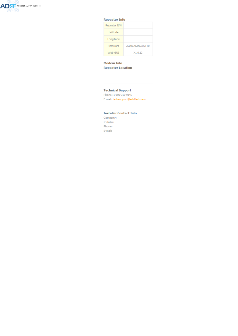
5.2.5 Repeater Info / Modem Info / Repeater Location / Technical Support / Installer Contact Info
Advanced RF Technologies, Inc.
29
Figure 5-7 Repeater Info / Modem Info / Repeater Location / Technical Support / Installer Contact Info
• Repeater Info: Displays the serial number, latitude, longitude, firmware version, Web-GUI version
• Modem Info: Displays the internal modem information (ESN, MDN, IP)
• Repeater Location: Displays the address where the repeater is installed
• Technical Support: Displays ADRF’s Technical Support contact information
• Installer Contact Info: Displays the installer’s name, phone and e-mail address
Note: Once successfully logged in, the repeater model name and the site/cascade ID will be
displayed on the top of all the windows (except for the Main Window).
Advanced RF Technologies, Inc.
30
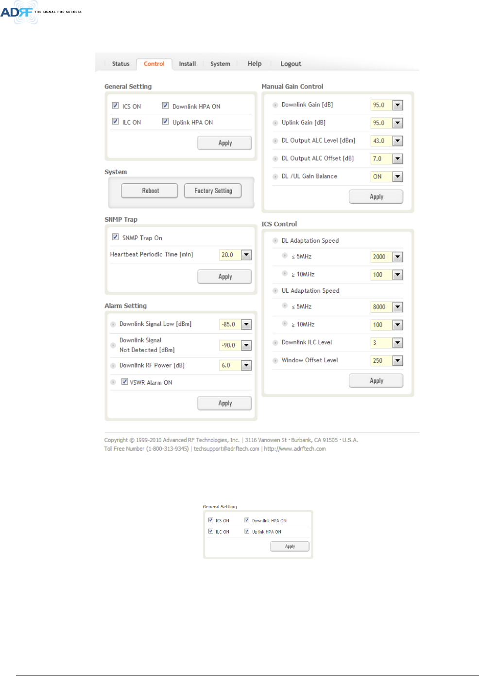
5.3 Control Tab
Figure 5-8 Control page
5.3.1 General Setting
Figure 5-9 General Setting
• ICS ON: Enables or disables the Interference Cancellation System (ICS)
• ILC ON: Enables or disables the Interference Level Control (ILC)
• Downlink HPA ON: Enables or disables the DL HPA (High Power Amplifier)
• Uplink HPA ON: Enables or disabled the UL HPA (High Power Amplifier)
To enable any of the settings, click on the checkbox and click the Apply button.
Advanced RF Technologies, Inc.
31
WARNING: Inserting a CW signal into the AXM700F-9543-ICS-X when ICS is enabled will cause the system to
generate a false alarm. The false alarm will cause the system to go into a shutdown state. If a CW signal
needs to be injected into the repeater for testing purposes, the ICS routine must be turned off.
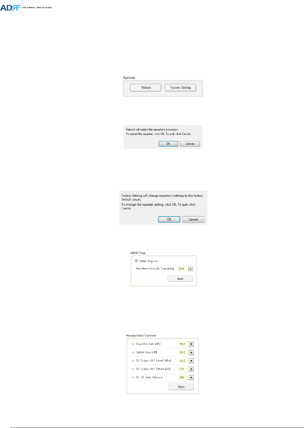
5.3.2 System
Figure 5-10 System
• Reboot: Clicking the reboot button will have the following popup show up:
Figure 5-11 Pop-up message when Reboot button is pressed
Click OK to reboot the repeater or click Cancel to exit out
• Factory Setting: Resets the repeater to the original factory settings
Figure 5-12 Pop-up message when Factory Setting button is pressed
5.3.3 SNMP Trap
Figure 5-13 SNMP Trap
• SNMP Trap ON – Enables or Disables SNMP traps from being sent out when an alarm is triggered.
• Heartbeat Periodic Time [min] – Specifies the amount time between heartbeats
5.3.4 Manual Gain Control
Figure 5-14 Manual Gain Control Setting
• Downlink Gain/Uplink Gain: Allows the UL gain to be adjusted manually when ALC is OFF
Advanced RF Technologies, Inc.
32
• DL Output ALC Level: Prevents the output power from exceeding the specified value
• DL Output ALC Offset: When the incoming signal level increases, the system will not adjust the attenuation
levels until the delta reaches the level specified
• DL /UL Gain Balance ON: Allows the user to enable or disable the gain balance. When gain balance is enabled,
the delta value between the downlink and uplink gains remain constant
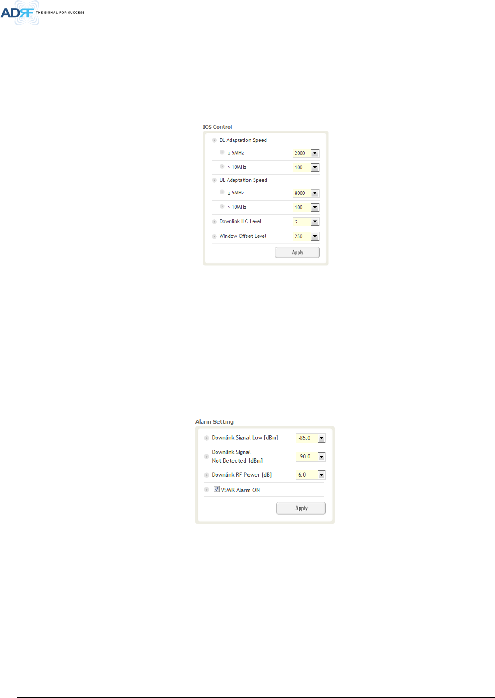
5.3.5 ICS Control
Figure 5-15 ICS Control Setting
• DL/UL Adaptation Speed : Allows the user to specify the speed of the ICS engine. Setting this value too high
may impact EVM and could reduce the throughput speeds. Adaptation speeds can be adjusted based on the
selected bandwidth.
• Downlink ILC Level : Allows the user to specify the interference level control. The measured isolation value +
ILC Level will provide you with the MAX gain level. When the ILC Level + User Set Gain Level is larger than the
measured isolation value, ILC will adjust the gains levels to match the measure isolation value.
• Window Offset : Allows the user to shift the ICS cancellation window.
5.3.6 Alarm Setting
Figure 5-16 Alarm Threshold Setting
• Downlink Signal Low: Allows the user to specify how low the signal can be before triggering a “Downlink
Signal Low” soft-fail alarm
• Downlink Signal Not Detected: Allows the user to specify how low the signal can be before triggering a
“Downlink Signal Not Detected” soft-fail alarm
• Downlink RF Power: Allows the user to set a maximum deviation value for the downlink RF power
- For example, if the input signal is -50 dBm and the gain is set to 60 dB, the expected output power should
be 10 dBm. If the Downlink RF Power alarm value is set to 6dB, then if the output power is below 4 dBm,
then this will trigger a soft-fail alarm
• VSWR Alarm ON: Allows the user to enable/disable the VSWR alarm check
Advanced RF Technologies, Inc.
33
5.4 Install Tab
5.4.1 Install
Figure 5-17 Install page
5.4.2 SNMP
Figure 5-18 SNMP
The SNMP section allows you to specify the Site ID and Manager IP. The Site-ID is the code that is used to
identify a particular module. The Manager IP field is where the user inputs the IP address of the NOC system that
is being used to monitor the SNMP traps.
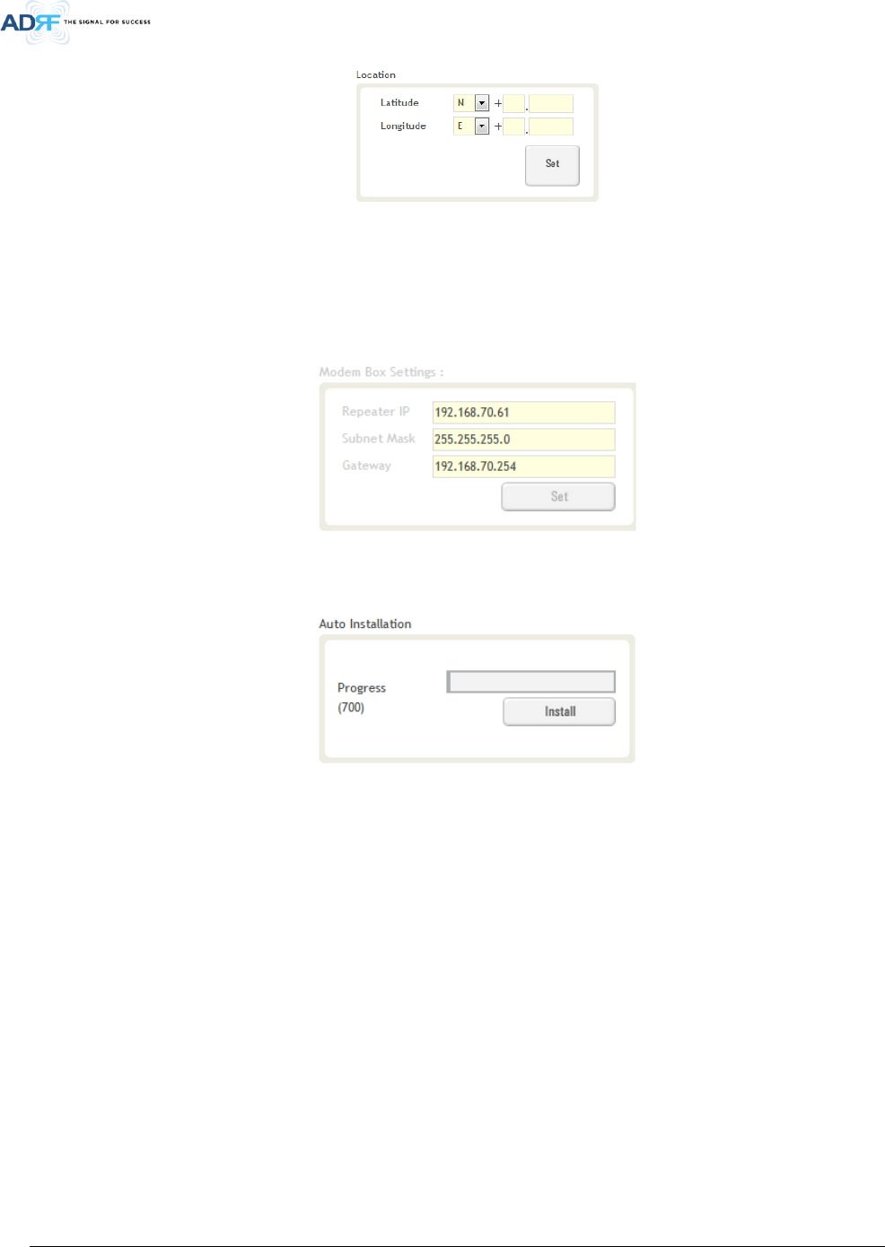
5.4.3 Location
This section allows the user to input the latitude and the longitude of the repeater.
Advanced RF Technologies, Inc.
34
Figure 5-19 Location Setting
5.4.4 Modem Box Settings
This section allows the user to specify an alternative Repeater IP, Subnet Mask, and Gateway settings. These
settings are enabled when the Host/Remote switch is set to the Remote position. When the Host/Remote switch
is changed, the repeater will reboot and will result in a temporary loss in coverage.
Figure 5-20 Modem Box Setting
5.4.5 Auto Installation
Figure 5-21 Auto Installation
The Auto Installation routine can be run by clicking on the Install button. The Auto Installation routine runs
basic system checks to ensure proper functionality.
Advanced RF Technologies, Inc.
35
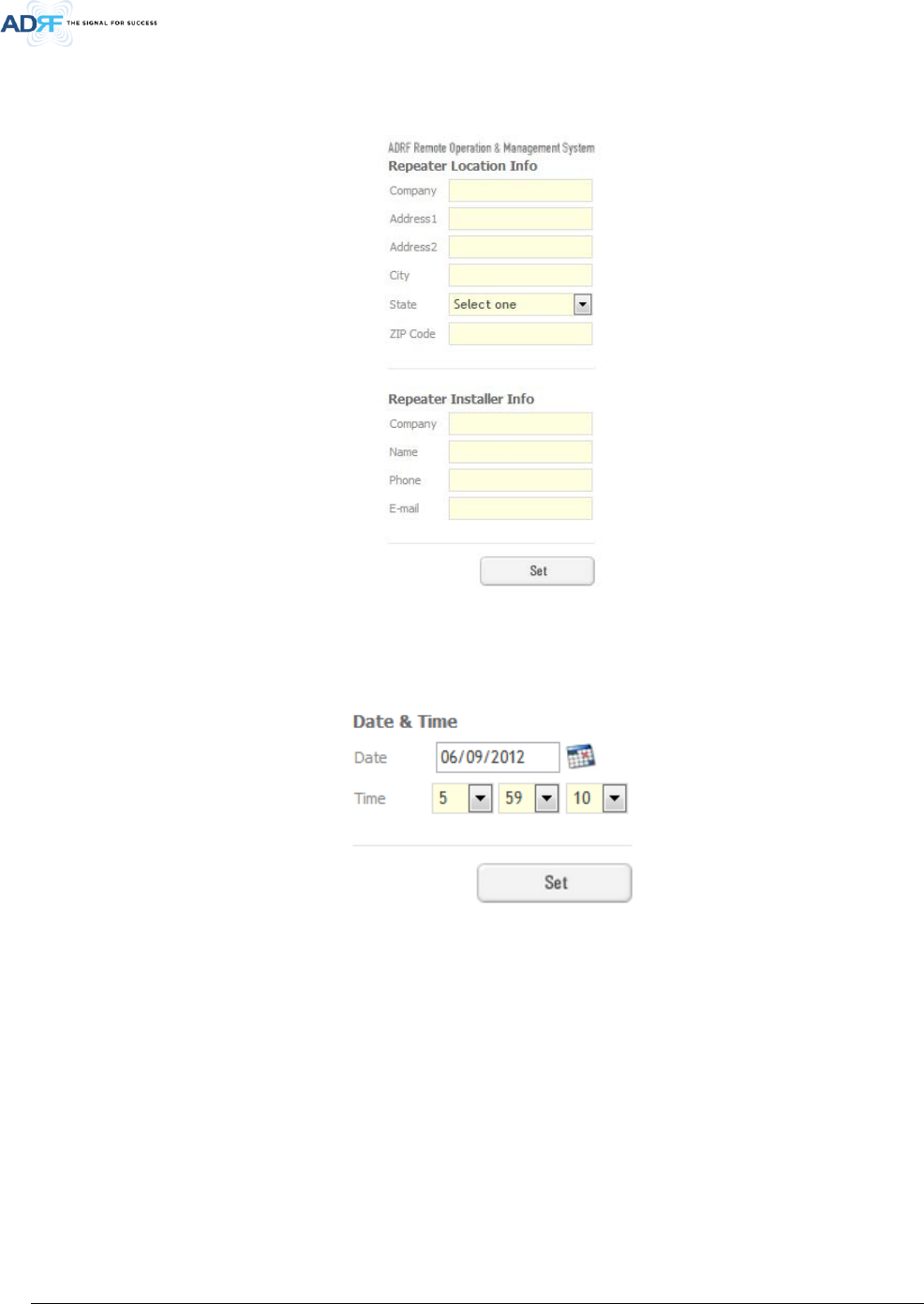
5.4.6 Repeater Location Info / Repeater Installer Info
This section allows the user to specify the address of the repeater and also the information of the installer.
Figure 5-22 Repeater Location Info / Repeater Installer Info
5.4.7 Date & Time
This section allows the user to specify the current date and time.
Figure 5-23 Date & Time Setting
Advanced RF Technologies, Inc.
36
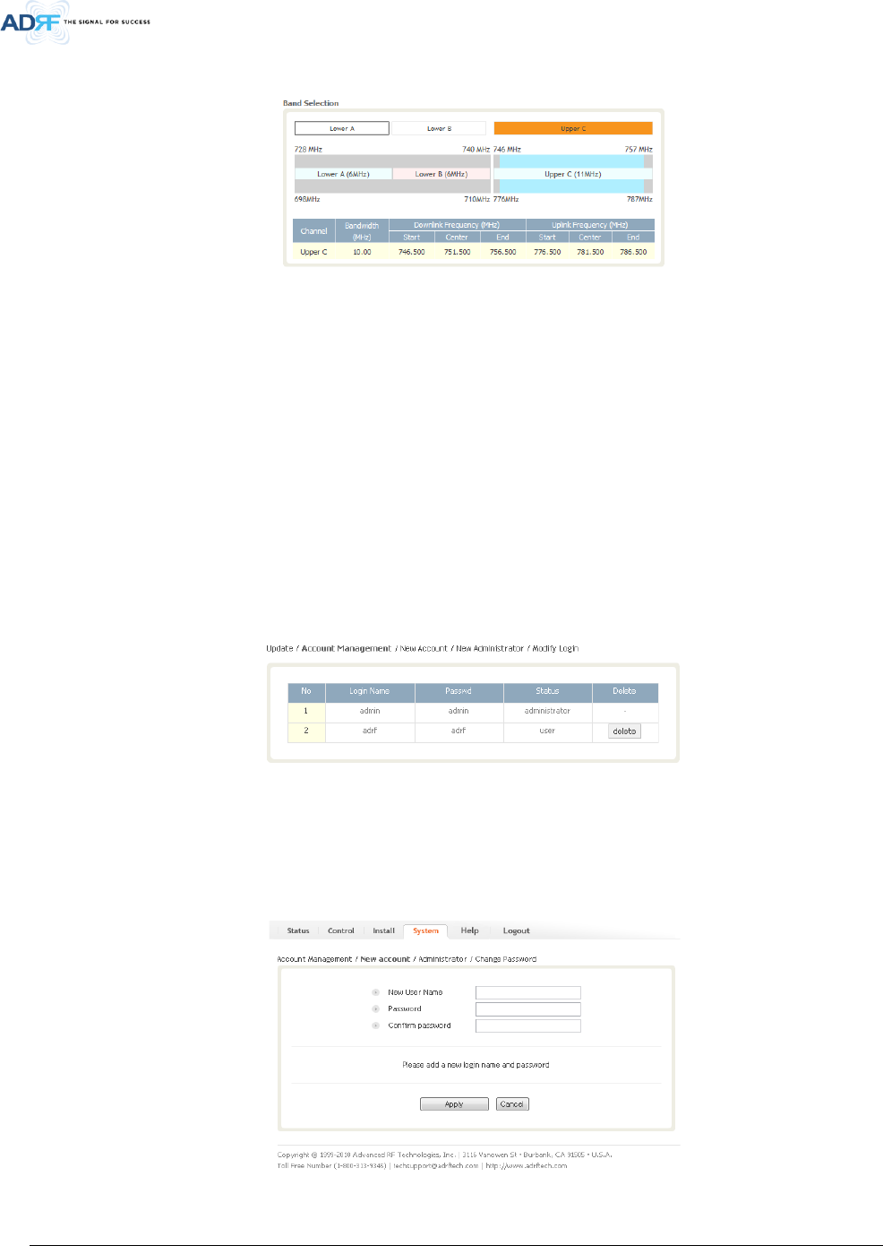
5.4.8 Band Selection
Figure 5-24 Band Selection
Band selection allows the user specify the desired frequncies by clicking on the preset 700 MHz band.
Available choices include Lower A, Lower B, Lower A + Lower B, or Upper C.
5.5 System
The System tab allows the user to perform firmware updates, upload closeout packages, view any changes to
the system, backup existing configuration, and add/remove user accounts, and change the login credentials of the
Administrator.
5.5.1 System: Account
5.5.1.1 System: Account- Account Management
The Account Management section allows the Administrator to delete any user account. Please note that the
Account Management section is only available if you are logged into the system as the Administrator. To delete a
user account click on the Account Management link and under the Delete column, click on the delete button.
Figure 5-25 System: Account- Account Management
5.5.1.2 System: Account- New Account
The New account section allows the Administrator to create a new user account. Please note that the New
account section is only available if you are logged into the system as the Administrator. To create a new user
account click on the new account link and fill in the fields highlighted in yellow as shown below.
Figure 5-26 System: Account- New Account
Advanced RF Technologies, Inc.
37
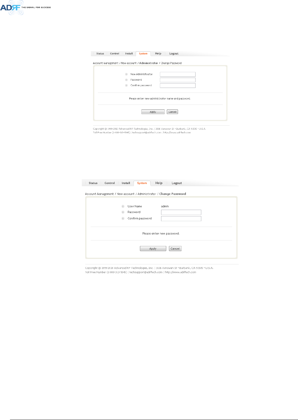
5.5.1.3 System: Account- Administrator
The Administrator section allows the Administrator to create additional Administrator accounts. Please note
that the Administrator section is only available if you are logged into the system as the Administrator.
Figure 5-27 System: Account- Administrator
5.5.1.4 System: Account- Change Password
The Change Password section allows the current user who is logged into the system to change their login
credentials.
Figure 5-28 System: Account- Change Password
Advanced RF Technologies, Inc.
38
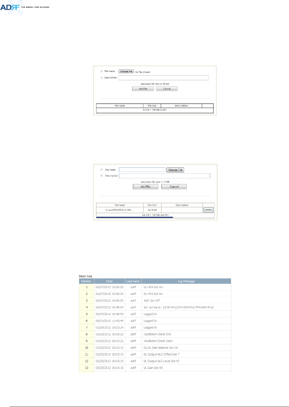
5.5.2 System- Closeout Package
The closeout package section will allow the user to upload documents to the module. The maximum file size
for each upload is limited to 10 MB. The total amount of space available for uploading document is 100 MB.
Please do not use this section as the primary storage location of your documents. Documents may become
unavailable if the system goes down.
Figure 5-29 System- Closeout Package
To upload documents to the module, click on the “Choose File” or “Browse” button and locate the file that you
would like to upload, then enter in a Description of the file being uploaded. Afterwards, click on the “Add File”
button to upload the file. Below is what you will see after the file upload. To delete the file, click on the delete
button located in the last column.
Figure 5-30 System- Closeout Package after the file upload
5.5.3 System- User Log
This section displays system events that have taken place. The User Log displays who has made the changes,
the time and date of when the event took place, and what changes were made to the system.
Figure 5-31 System – User Log
Advanced RF Technologies, Inc.
39
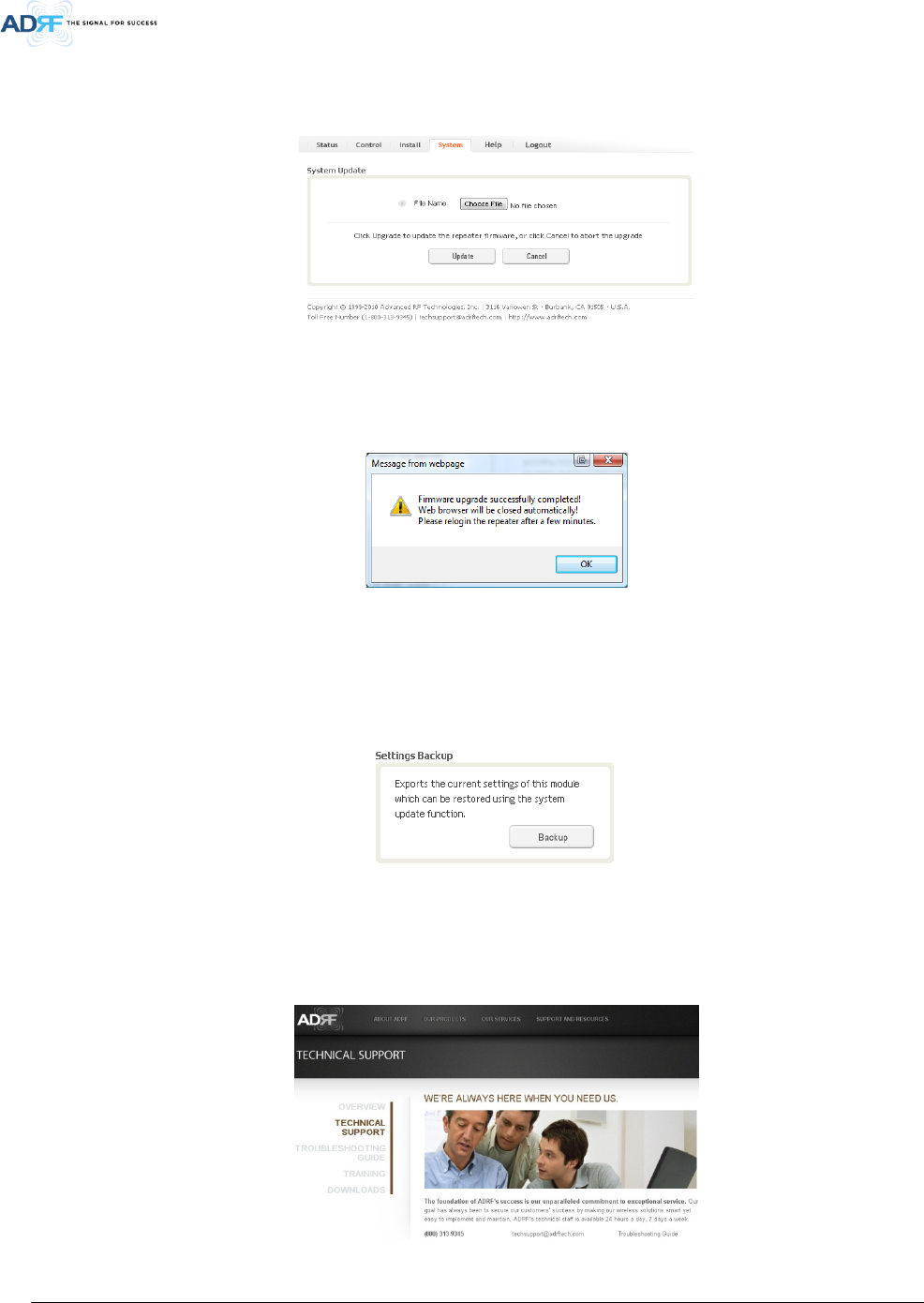
5.5.4 System: Update
• To perform a firmware update, click on the System tab and the following screen will appear.
Figure 5-32 System – Update
• Click on the Choose File… button and locate the firmware file
• Click on the Upload button to perform the firmware update
• Once the firmware update is complete, the following popup message will appear:
Figure 5-33 Pop-up message after System update is complete
5.5.5 System- Backup
The backup section allows the user to save the settings of the module. To perform the backup, click on the
Backup button and you will be prompted to save the backup file. To restore the settings to the system, perform an
update using this file.
Figure 5-34 System Backup
5.6 Help
If an internet connection is available, clicking on the Help Tab will redirect the user to our Technical Support
page.
Figure 5-35 Help

Advanced RF Technologies, Inc.
40
5.7 Logout
Clicking the Logout button will log the current user off the system.
6. MAINTENANCE GUIDE FOR AXM700F-9543-ICS-X REPEATER
6.1 Periodic Inspection Checklist
• Check for loose connections between the repeater and antennas. If connections are loose, make sure that all
connections are tightly fastened properly.
• Cables and connectors are in good condition.
• Ensure that the repeater brackets are in good. condition and that the repeater is securely fastened
6.2 Preventive Measures for Optimal Operation
6.2.1 Recommendations
• Perform the Periodic Inspection Checklist quarterly or semi-annually.
6.2.2 Precautions
• Do not operate the repeater with the antennas in extremely close proximity to one another as this may cause
damage to the repeater.
• Do not change the parameters unless instructed to do so by an authorized supervisor.
• Do not move the repeater unless instructed to do so by an authorized supervisor.
• Do not detach any cables to the repeater unless repair of respective components is necessary.
7. WARRANTY AND REPAIR POLICY
7.1 General Warranty
The AXM700F-9543-ICS-X carries a Standard Warranty period of two (2) years unless indicated otherwise on
the package or in the acknowledgment of the purchase order.
7.2 Limitations of Warranty
Your exclusive remedy for any defective product is limited to the repair or replacement of the defective
product. Advanced RF Technologies, Inc. may elect which remedy or combination of remedies to provide in its sole
discretion. Advanced RF Technologies, Inc. shall have a reasonable time after determining that a defective product
exists to repair or replace the problem unit. Advanced RF Technologies, Inc. warranty applies to repaired or
replaced products for the balance of the applicable period of the original warranty or ninety days from the date of
shipment of a repaired or replaced product, whichever is longer.
7.3 Limitation of Damages
The liability for any defective product shall in no event exceed the purchase price for the defective product.
7.4 No Consequential Damages
Advanced RF Technologies, Inc. has no liability for general, consequential, incidental or special damages.
7.5 Additional Limitation on Warranty
Advanced RF Technologies, Inc. standard warranty does not cover products which have been received
improperly packaged, altered, or physically damaged. For example, broken warranty seal, labels exhibiting
tampering, physically abused enclosure, broken pins on connectors, any modifications made without Advanced RF
Technologies, Inc. authorization, will void all warranty.
Advanced RF Technologies, Inc.
41
7.6 Return Material Authorization (RMA)
No product may be returned directly to Advanced RF Technologies, Inc. without first getting an approval from
Advanced RF Technologies, Inc. If it is determined that the product may be defective, you will be given an RMA
number and instructions in how to return the product. An unauthorized return, i.e., one for which an RMA number
has not been issued, will be returned to you at your expense. Authorized returns are to be shipped to the address
on the RMA in an approved shipping container. You will be given our courier information. It is suggested that the
original box and packaging materials should be kept if an occasion arises where a defective product needs to be
shipped back to Advanced RF Technologies, Inc. To request an RMA, please call (800) 313-9345 or send an email to
techsupport@adrftech.com.
8. SPECIFICATIONS
8.1 Electrical Specifications
Table 8-1 Electrical Specifications
Parameters Specifications Comments
Frequency
DL
728~746 MHz
746~758 MHz
UL
698~716 MHz
776~788 MHz
Frequency Error 0.05ppm
ICS LTE 5MHz, 10MHz
SDR 0.25~18MHz(0.25MHz/Step)/channel, total 3 channels
Gain Flatness
Full Band ±1.5dB
Each Band ±1.5dB
Gain
Maximum 95dB
Step 0.5dB
Range 40dB
Tolerance ±1dB
Spurious Emissions Meet FCC Rule
Out Band Spurious Emissions
-13dBm/1kHz; 9KHz<f<150KHz
-13dBm/10kHz; 150KHz<f<30MHz
-13dBm/100kHz; 30MHz<f<1GHz
-13dBm/1MHz; 1GHz<f<12.75GHz
Composite Output Power
(DL/UL)
DL +43dBm
UL +30dBm
Cancellation Window 6.0 us
Required Minimum Isolation Gain-5dB Only direct feedback signals exist
EVM < 12.5%
Roll Offs > 50dBc@ 1MHz Outside pass-band
Noise Figure(Uplink) 6dB@ Maximum Gain
Advanced RF Technologies, Inc.
42
VSWR 1.5:1
IN/OUT IMPEDANCES 50Ω
8.2 Mechanical Specifications
Table 8-2 Mechanical Specifications
Parameters Specifications Comments
Dimension 430*270*562(mm, W*D*H)
Bracket excluded, dependent to
Duplexer
Weight 38.5Kg Bracket excluded
RF Ports DIN-Type Female Donor & Server Antenna Ports
Local Interface Ethernet
Cooling FAN
IP Class NEMA4X
Mounting Type Wall Mounting
8.3 Power Specifications
Table 8-3 Power Specifications
Parameters Specifications Comments
AC Power
120V / 230V
Select Switch Type
AC Supply Protection
Fuse & Circuit Protector
T6.3L250V
Battery Backup
24V/22A
Power Consumption
AC 500W(120V/6A), DC 24V/22A
Ground
External Threaded Stud
8.4 Environment Specifications
Table 8-4 Environment Specifications
Parameters Specifications Comments
Operating Temperature -30~+55℃
Relative Humidity 5~95%, (Non-Condensing)
8.5 Warranty & Certificates
Table 8-5 Warranty & Certificates
Parameters Specifications Comments
MTBF > 100,000 Hours Ambient
Compliance
UL60950
FCC CFR47 part 15
Advanced RF Technologies, Inc.
43
FCC CFR47 part 27
Warranty 2 Years
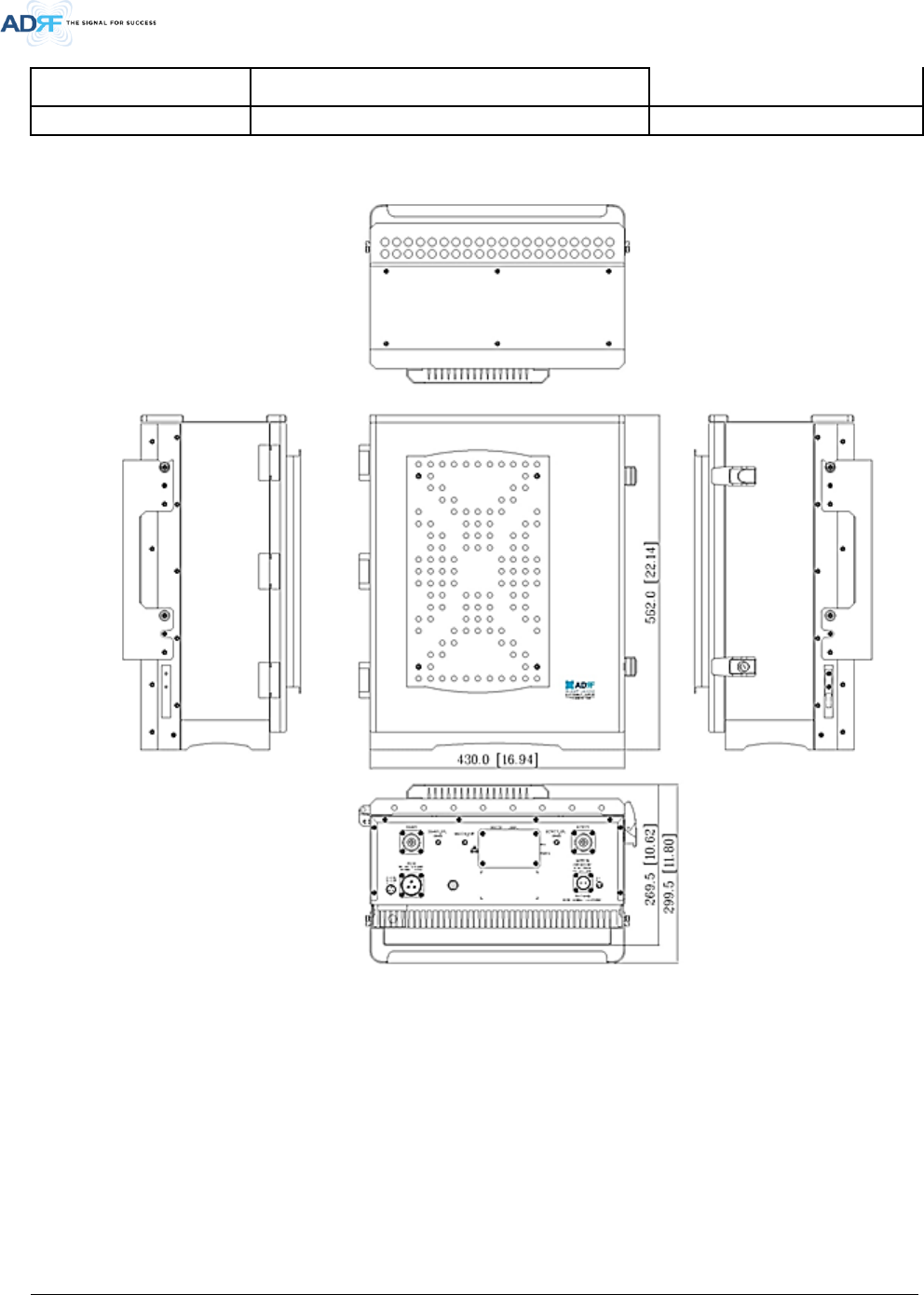
9. MECHANICAL DRAWING
Figure 9-1 AXM700F-9543-ICS-X Mechanical Drawing

Advanced RF Technologies, Inc.
44
10. APPENDIX
10.1 Shutdown Retry Logic
The function of the built-in shutdown routine is to protect the repeater from any further damage from a hard-
fail that the system may be experiencing.
Within 5 seconds of a hard-fail alarm being detected, the repeater will start the shutdown routine. The
repeater will shut down by powering of the HPAs (high-powered amplifiers) for 30 seconds.
After 30 seconds have elapsed, the repeater will power on the HPAs and check to see if the hard-fail alarm still
exist. If the hard-fail alarm still exists, then the repeater will shut down for 1 minute (double the time of the
previous shutdown time).
After 1 minute has elapsed, the repeater will power on the HPAs and check to see if the hard-fail alarm still
exist. If the hard-fail alarm still exists, then the repeater will shut down for 2 minutes (double the time of the
previous shutdown time).
The shutdown routine will repeat itself a total of 10 times. If the hard-fail alarm still exists after the 10th retry,
then the repeater will turn off its HPAs permanently until a reset is performed or factory set is executed.