ADRF KOREA PSR-VU-9537B Repeater User Manual PSR VU 9537 Installation and Operating Manual
ADRF KOREA, Inc. Repeater PSR VU 9537 Installation and Operating Manual
PSR-VU-9537_User Manual-B9B

Advanced RF Technologies, Inc.
ii
Information in this document is subject to change without notice.
Advanced RF Technologies, Inc. 1996-2015.
All rights reserved.
• Please send comments to:
E-Mail: info@adrftech.com
Phone: (818) 840-8131
(800) 313-9345
Fax: (818) 840-8138
• Address:
Advanced RF Technologies, Inc.
Attention: Technical Publications Department
3116 Vanowen St.
Burbank, CA 91505
USA
www.adrftech.com
Advanced RF Technologies, Inc.
iii
Revision History
Change List
Version Change list Contents
Version Author Descriptions Date
0.1
YH Ko
Initial Release
03/07/16
0.2
CK JO
Revision Update
01/10/17
0.3
CK JO
Class B Addition
01/16/17

Advanced RF Technologies, Inc.
iv
Table of Contents
1. Introduction ........................................................................................................................................................ 6
1.1 Highlights ..................................................................................................................................................... 6
1.2 Quick View ................................................................................................................................................... 7
1.3 Warnings and Hazards ................................................................................................................................. 8
2. Cable Connection .............................................................................................................................................. 12
2.1 AC Power ................................................................................................................................................... 12
2.2 External Alarm ........................................................................................................................................... 12
2.3 RF ............................................................................................................................................................... 12
2.4 Battery ....................................................................................................................................................... 13
2.5 Grounding .................................................................................................................................................. 13
3. RF EXPOSURE WARNING ................................................................................................................................... 14
4. Installation ........................................................................................................................................................ 14
5. default items ..................................................................................................................................................... 15
6. Specification ...................................................................................................................................................... 15
Figures
Figure 1-1 PSR-VU-9537 Quick View (front and bottom) ...................................................................................... 7
Figure 2-1 AC Power port..................................................................................................................................... 12
Figure 2-2 External Alarm port ............................................................................................................................ 12
Figure 2-3 Protective Earthing Conductor ........................................................................................................... 13

Advanced RF Technologies, Inc.
5
Terms and Abbreviations
The following is a list of abbreviations and terms used throughout this document.
Abbreviation/Term Definition
AGC Automatic Gain Control
ALC Automatic Level Control
AROMS ADRF’ Repeater Operation and Management System
BCU Band Combiner Unit
BTS Base Transceiver Station
BDA Bi-directional Amplifier
CDMA Code Division Multiple Access
CHC Channel combiner
CW Continuous Wave (un-modulated signal)
DAS Distributed Antenna System
DL Downlink
Downlink The path covered from the Base Transceiver Station (BTS) to the subscribers’ service area
via the repeater
HE Head End
HPA High Power Amplifier
HW Hardware
IF Intermediate Frequency
LNA Low Noise Amplifier
LTE Long Term Evolution
MS Mobile Station
NMS Network Management System
ODU Optical Donor Unit which is located in ADXV-HE.
OEU Optic Expansion Unit
PLL Phased Locked Loop
POI Point Of Interface
PSU Power Supply Unit
RF Radio Frequency
RU Remote Unit which is composed of master RU and multiple slaves RU
RM Remote Module
SW Software
UL Uplink
Uplink The path covered from the subscribers’ service area to the Base Transceiver Station (BTS)
via the repeater
VSWR Voltage Standing Wave Ratio

Advanced RF Technologies, Inc.
6
1. INTRODUCTION
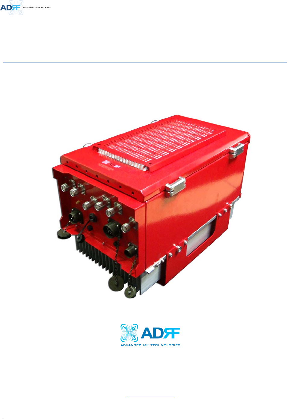
PSR-VU-9537 bi-directional amplifier (BDA) extends the coverage area of radio communications in buildings and RF
shadow environments.
The unit features low noise figure and wide dynamic range.
1.1 Highlights
• Single band choosable between VHF or UHF band by GUI
• Simultaneous Filter Supporting 1 Wide Band and Up to 8 Non-Contiguous Narrow Bands
• Fanless
• Significant Filter Roll-off performance (Wide: 65dBc@Filter Bandwidth Edge + 500KHz | Narrow: 60dBc@Filter
Bandwidth Edge + (Filter BW / 2))
• Supports SNMP v1, v2, v3 (get, set & traps)
• Web-based GUI Interface; No 3rd party GUI software required
• Web-GUI connectivity via DHCP in host mode
• Extenal Alarm Function supporting dry contacts 8 outputs and 2 inputs
Advanced RF Technologies, Inc.
7
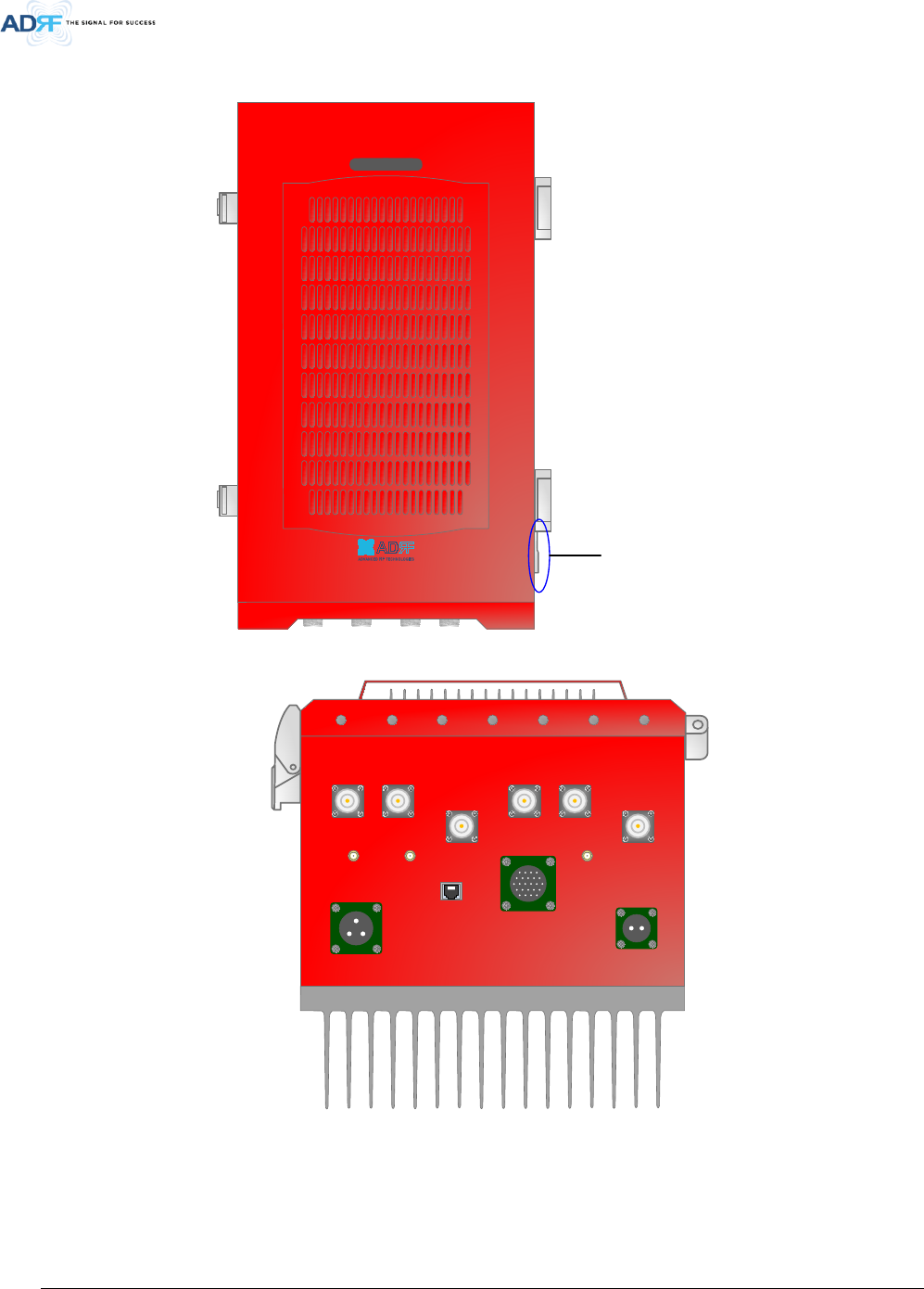
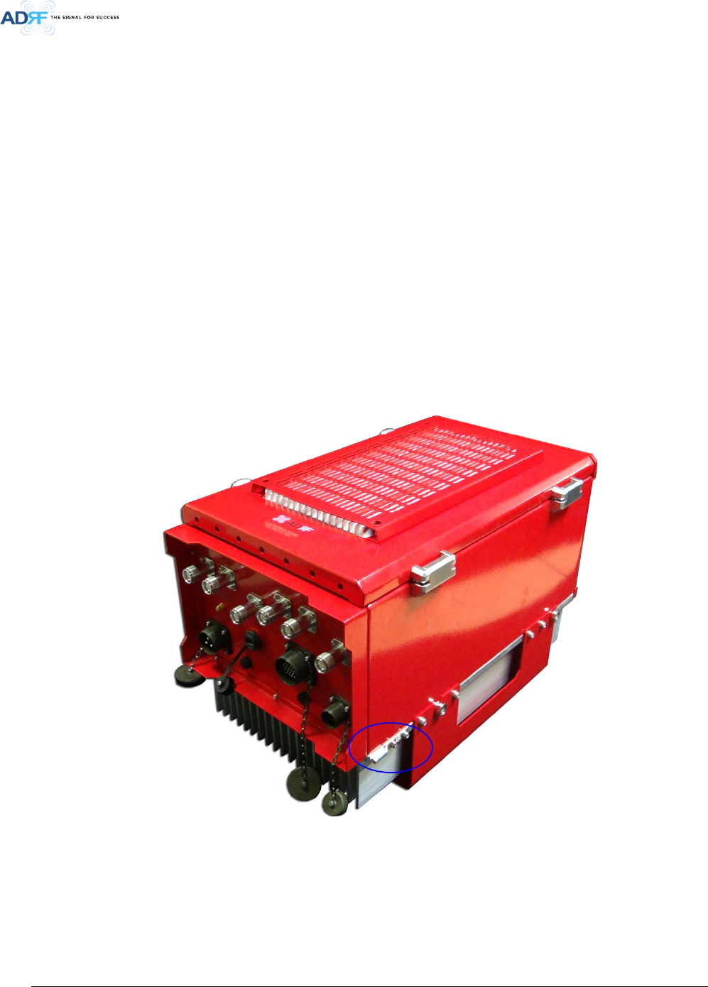
1.2 Quick View
Figure 1-1 PSR-VU-9537 Quick View (front and bottom)
PSR-VU-9537
Ground terminal
DL DONOR UL DONOR
DONOR
DL SERVER UL SERVER
SERVER
GUI
Ext. ALARM
MODEM_ANT DONOR_CPL
(-30dB) SERVER_CPL
(-30dB)
AC 100-240V BATTERY
ADRF-BBU ONLY
Advanced RF Technologies, Inc.
8
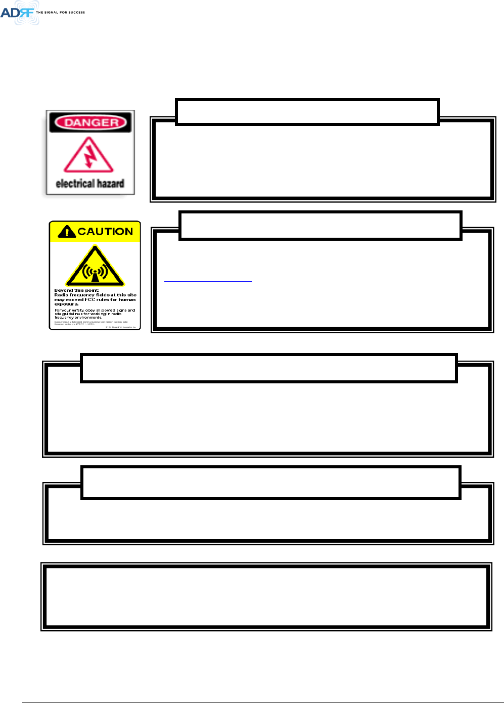
1.3 Warnings and Hazards
Opening the PSR-VU-9537 could result in electric shock and may cause
severe injury.
WARNING!
ELECTRIC
SHOCK
Working with the PSR-VU-9537 while in operation, may expose the technician to RF
electromagnetic fields that exceed FCC rules for human exposure. Visit the FCC website at
www.fcc.gov/oet/rfsafety to learn more about the effects of exposure to RF electromagnetic
fields.
WARNING! EXPOSURE TO RF
Actual separation distance is determined upon gain of antenna used.
Please maintain a minimum safe distance of at least 500 cm while operating near the donor and
the server antennas.
RF EXPOSURE & ANTENNA PLACEMENT Guidelines
Opening or tampering the PSR-VU-9537 will void all warranties.
WARRANTY
Lithium Battery: CAUTION. RISK OF EXPLOSION IF BATTERY IS REPLACED BY INCORRECT TYPE.
DISPOSE OF USED BATTERIES ACCORDING TO INSTRUCTIONS.
Advanced RF Technologies, Inc.
9
Preclude indications that Home/ personal use are prohibited.
Use of unauthorized antennas, cables, and/or coupling devices not conforming with ERP/EIRP is
prohibited.
NOTE: This equipment has been tested and found to comply with the limits for a Class B digital
device, pursuant to part 15 of the FCC Rules. These limits are designed to provide reasonable
protection against harmful interference when the equipment is operated in a commercial
environment. This equipment generates, uses, and can radiate radio frequency energy and, if not
installed and used in accordance with the instruction manual, may cause harmful interference to
radio communications. Operation of this equipment in a residential area is likely to cause harmful
interference in which case the user will be required to correct the interference at their own
expense.
FCC Part 15 Class B
WARNING. THIS is NOT a CONSUMER device. It is designed for installation by FCC LICENSEES and
QUALIFIED INSTALLERS. You MUST have an FCC LICENSE or express consent of an FCC Licensee to
operate this device. You MUST register Class B signal boosters (as defined in 47 CFR 90.219) online
at
www.fcc.gov/signal-boosters/registration. Unauthorized use may result in significant forfeiture
penalties, including penalties in excess of $100,000 for each continuing violation.
FCC Part 90 Class B
Any changes or modifications not expressly approved by the party responsible for compliance could
void the user's authority to operate this equipment.
FCC Part 15.21
Advanced RF Technologies, Inc.
10
Under Industry Canada regulations, this radio transmitter may only operate using an antenna of a type
and maximum (or lesser) gain approved for the transmitter by Industry Canada. To reduce potential
radio interference to other users, the antenna type and its gain should be so chosen that the equivalent
isotropically radiated power (e.i.r.p.) is not more than that necessary for successful communication.
Conformément à la réglementation d’Industrie Canada, le présent émetteur radio peut
fonctionneravec une antenne d’un type et d’un gain maximal (ou inférieur) approuvé pour l’émetteur
par Industrie Canada.
Dans le but de réduire les risques de brouillage radioélectrique à l’intention desautres utilisateurs,
il faut choisir le type d’antenne et son gain de sorte que la puissance isotroperayonnée quivalente
(p.i.r.e.) ne dépassepas l’intensité nécessaire à l’établissement d’une communication satisfaisante.
RSS-GEN, Sec. 7.1.2– (transmitters)
This radio transmitter (identify the device by certification number, or model number if Category II)has
been approved by Industry Canada to operate with the antenna types listed below with the maximum
permissible gain and required antenna impedance for each antenna type indicated. Antenna types not
included in this list, having a gain greater than the maximum gain indicated for that type, are strictly
prohibited for use with this device.
Le présent émetteur radio (identifier le dispositif par son numéro de certification ou son numéro de
modèle s’il fait partie du matériel de catégorie I) a été approuvé par Industrie Canada pour fonctionner
avec les types d’antenne énumérés ci-dessous et ayant un gain admissible maximal et l’impédance
requise pour chaque type d’antenne. Les types d’antenne non inclus dans cette liste,ou dont le gain
est supérieur au gain maximal indiqué, sont strictement interdits pour l’exploitation de l’émetteur.
RSS-GEN, Sec. 7.1.2– (detachable antennas)
This equipment complies with RF radiation exposure limits set forth for an uncontrolled environment.
This equipment should be installed and operated with a minimum distance of 500 cm between the
radiator and your body. This transmitter must not be co-located or operating in conjunction with any
other antenna or transmitter. RF exposure will be addressed at time of installation and the use of
higher gain antennas require larger separation distances.
RF Radiation Exposure

Advanced RF Technologies, Inc.
11
L’antenne (ou les antennes) doit être installée de façon à maintenir à tout instant une distance
minimum de au moins 500 cm entre la source de radiation (l’antenne) et toute personne physique.
Cet appareil ne doit pas être installé ou utilisé en conjonction avec une autre antenne ou émetteur.
RSS-102 RF Exposure
Advanced RF Technologies, Inc.
12
2. CABLE CONNECTION
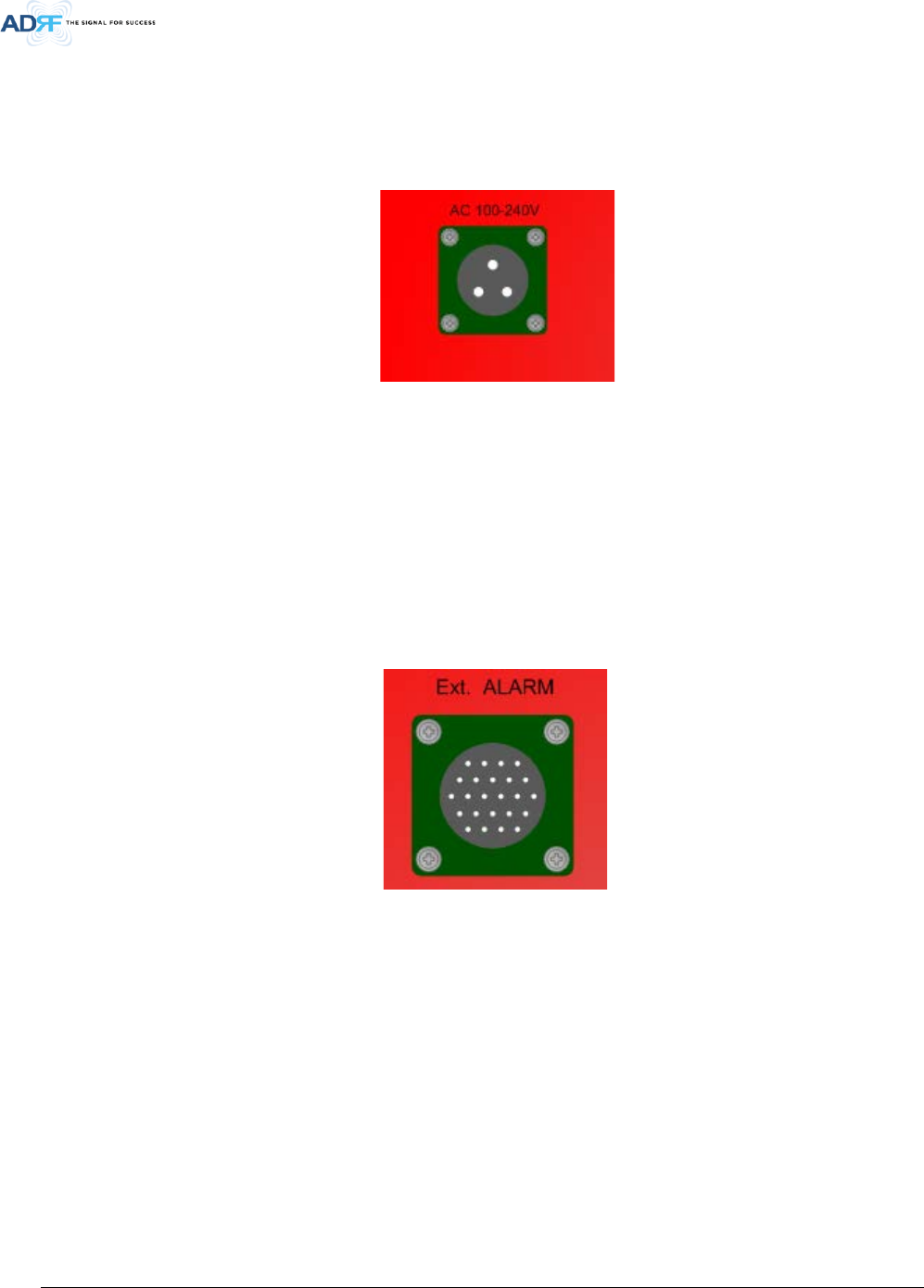
2.1 AC Power
Figure 2-1 AC Power port
AC power is accepted through a standard 3-wire male plug (MS3106A-22-2S) with phase, neutral and ground leads.
The AC power is wired to a high efficiency DC switching power supply which is UL approved. The power supply runs
the amplifiers and device including RF Module, controller, LED, etc.
The metal enclosure of the BDA is connected to ground.
2.2 External Alarm
Figure 2-2 External Alarm port
This port should be connected only to ADRF External Alarm Box.
2.3 RF
The RF connections are made via two type “4.3-10” female connectors. The RF connector labeled “DONOR” must be
connected to the antenna pointing towards the base station. The RF connection labeled “SERVER” must be
connected to the antenna facing the area to be covered by the BDA.
The RF connections must be made through cables with characteristic impedance of 50 ohms.
Separation between the antennas is necessary to prevent oscillation. Oscillation occurs when the signal entering the
system continually reenters, due to the lack of separation between the donor and server antennas. In other words,
Advanced RF Technologies, Inc.
13
the signal is being fed back into the system. This creates a constant amplification of the same signal. As a result, the
noise level rises above the signal level.
To prevent feedback, the donor and server antennas must be separated by an appropriate distance to provide
sufficient isolation. Isolation is attained by separating antennas a sufficient distance so that the output of one
antenna does not reach the input of the other. This distance is dependent on the gain of the repeater.
2.4 Battery
This port should be connected to ADRF 48VDC BBU(Battery back-up unit) via dedicated cable provided by ADRF.
2.5 Grounding
A ground cable is included in the box. The grounding terminals are located at lower right-hand side of the BDA.
The grounding cable should be properly connected before powering on the equipment.
Figure 2-3 Protective Earthing Conductor
Ground terminals located on the side consisted of a 1.25mm²(16AWG) and should be permanently connected
to earth(Protective earthing conductor).
Advanced RF Technologies, Inc.
14
3. RF EXPOSURE WARNING
In order to comply with the FCC RF exposure requirements, the BDA’s antenna installation must comply with the
following:
The outdoor antenna (Yagi type or similar directional antenna if off air donor signal used) must be installed so as to
provide a minimum separation distance of 0.3 meters (60 cm) between the antenna and persons within the area.
(This assumes a typical antenna with gain of [10.1 dBi, VSWR ≤ 1.5:1, Zo= 50 ohms, and a cable attenuation between
1-10 dB).
The indoor antenna (Omni directional or leaky cable) must be installed so as to provide a minimum separation
distance of at least 8 inches (20 cm) between the indoor antenna connected to the RF booster and the human user’s
body within the area. (This assumes a typical wide beam type antenna with gain of 0-2 dBi, VSWR ≤ 2:1, Zo= 50
ohms, and a cable attenuation of between 1-10 dB).
4. INSTALLATION
DO NOT APPLY A.C. POWER TO THE BDA UNTIL CABLES ARE CONNECTED TO BOTH PORTS OF
THE BDA AND THE ANTENNAS.
1. To mount on a wall. Using appropriate screws and anchors, attach the BDA to the wall at the four mounting
holes
2. Ensure that the isolation between the donor antenna and the service antenna is at least 15 dB greater than
the BDA gain.
3. Connect the cable from the donor antenna to the BDA connector labeled “DONOR” and the cable from the
service antennas to the BDA connector labeled “SERVER”.
4. Connect the AC power cord to the BDA and turn on the switch at the left-hand of PSU.
5. Installation of the BDA is now complete. Adjust the gain controls to suit the specific signal environment
through GUI on your PC.
- To prevent feedback, the donor and server antennas must be separated by an appropriate distance to
provide sufficient isolation. Isolation is attained by separating antennas a sufficient distance so that the
Advanced RF Technologies, Inc.
15
output of one antenna does not reach the input of the other. This distance is dependent on the gain of the
repeater.
- Prior to equipment use the service must be registered with the FCC. This can be done through the FCC’s
website at https://signalboosters.fcc.gov/signal-boosters)
5. DEFAULT ITEMS
Items
Model name
Antenna
Cable
Coupling device
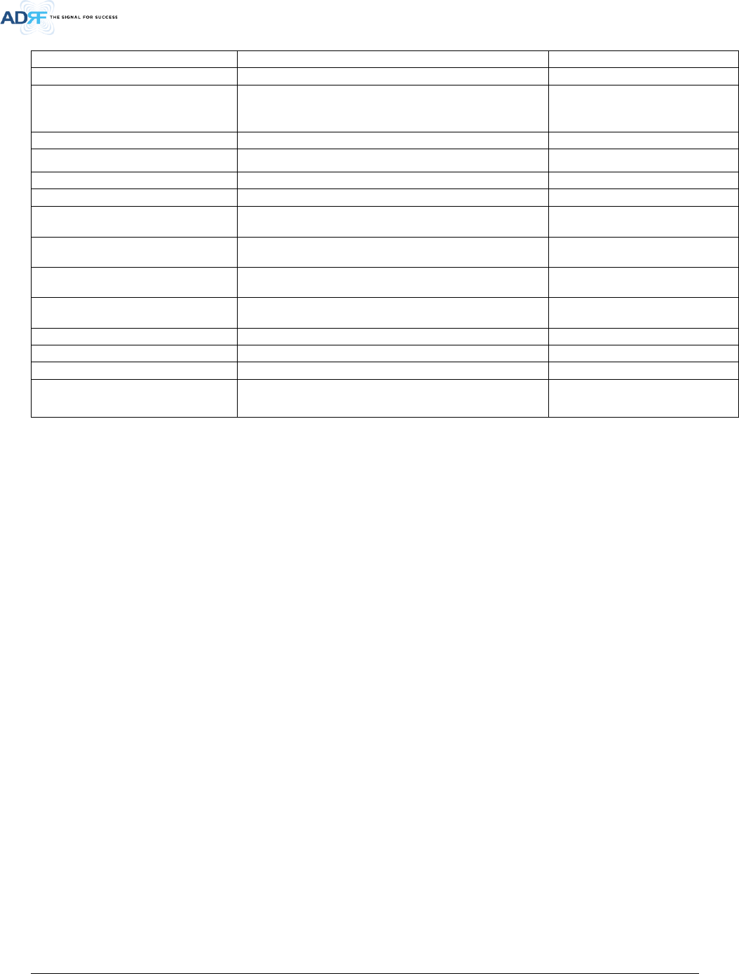
6. SPECIFICATION
Parameters
Specification
Remarks
DL UL
Frequency Range
(Nominal
Bandwidth)
(MHz)
VHF
FCC: 150~174 (24)
IC: 138~144 (6), 148~174 (26)
UHF
FCC: 406.1~470 (64.1), 470~512 (42)
IC: 406.1~430 (24.1), 450~470(20)
Composite Output
Power
VHF
28 dBm
24 dBm
UHF
37 dBm
27 dBm
Rated Mean
Output Power
VHF 28 dBm 24 dBm
Rated output power of this
equipment is for single carrier
operation. For situations when
multiple carrier signals are
present, the rating would have to
be reduced by 3.5 dB, especially
where the output signal is re-
radiated and can cause
interference to adjacent band
users. This power reduction is to
be by means of input power or
gain reduction and not by an
attenuator at the output of the
device.
UHF 37 dBm 27 dBm
Nominal Pass Band
Gain
(dB)
VHF
85
85
UHF
95(LMR450)
85(APCO25)
95(LMR450)
85(APCO25)
Filter selection
Wide or Narrow
Wide or Narrow
Support Filter
numbers
Wide
1
Narrow
Up to 8(Noncontiguous)
Filter Bandwidth Wide(MHz) 1/2/4/5
Future update available by custom
filter
Narrow(kHz)
75 ~331.25 (6.25 x n , n= 12~53)
Noncontiguous
Filter Roll-off
Wide: 65dBc@Filter Bandwidth Edge + 500KHz Narrow:
60dBc@Filter Bandwidth Edge + (Filter BW / 2)
Spurious
FCC meet
Passband Ripple
±2 dB
Any 15MHz BW
ALC Dynamic Range
60dB
Gain Dynamic Range
45dB
Advanced RF Technologies, Inc.
16
Channel Setting Resolution
0.5 kHz
Noise Figure @ Max. gain
3.5 dB
Without Duplexer
System Group Delay 5-240us
dependent on filter bandwidth
and required
adjacent channel
rejection
Power Supply
110 -240 VAC, 60 Hz (Free Voltage)
Power Consumption <216Watt
Max RF Input Power
-20dBm
No damage Max Input Power
+10 dBm
Impedance
Input : 50 Ohm
Output: 50 Ohm
RF Connector 4.3-10(Female)
VSWR <1.3:1
Operating Temperature -40°F to +140°F (-40°C to +60°C)
Humidity
10% - 90% RH Condensed
Dimensions W x D x H
12.0 x 13.0 x 21.7 in (w/out mount bracket)
Weight
65lbs (w/out mount bracket)
Enclosure IP66