HDC1287562G1_User Manual
jobAid
1
DESCRIPTION
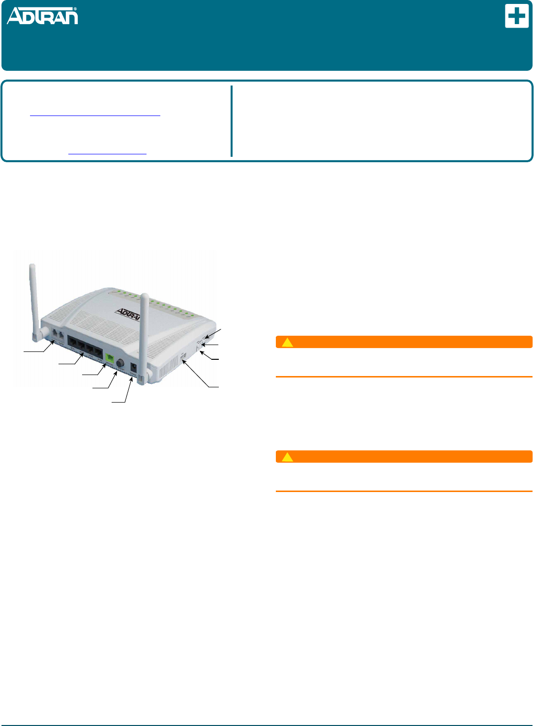
The Total Access 324RG Indoor 2 POTS + 4GigE (P/N 1287562G1)
Home Gateway Optical Network Termination (ONT) provides
Triple-Play services to a customer premises. The following is an
illustration of the Home Gateway ONT.
FEATURES
The Indoor 2 POTS + 4GigE has the following features:
Two POTS Interfaces
Four Ethernet fiber interfaces with 1.244 Gigabits per second
Upstream and 2.488 Gigabits per second downstream
One Optical Interface
AC Power Adapter
USB Interface
Voice Processing
POTS uses in-band signaling tones and currents to determine call
status (for example, call request). Because POTS allows for the
transfer of audio signals below 3.3 kHz, POTS systems are also
used for modems that allow data transmission (referred to as dial
up connections).
Ethernet Interface
The Home Gateway ONT supports data service through four 10/
100/1000Base-T Ethernet interfaces via an RJ-45-style connector.
Reset
Button
WPS Data
Encryption
Button
USB
Interface
Optical
Interface
Power
Connection
Power
On/O
Ethernet
Interfaces
POTS
Interfaces
WLAN
Button
Total Access 324RG
Indoor 2 POTS + 4GigE
Home Gateway ONT
Power
The power feed is 12 VDC.
INSTALLATION
Before installing the Home Gateway ONT, inspect it for damage.
If damage has occurred during shipping, file a claim with the
carrier and then contact ADTRAN. For more information, refer to
the warranty.
Installation Guidelines
The following are guidelines for this installation.
WARNING
!
Read all warnings and cautions before installing or servicing the
Home Gateway ONT.
Resetting the ONT
A reset button is available if the Home Gateway ONT needs to be
rebooted. To reset the Home Gateway ONT, insert a small pin
into the RESET opening and hole the button down for 5 seconds
or longer.
WARNING
!
All settings will return to Factory Defaults: Registration
provisioning will be lost.
Resetting the WLAN
The Home Gateway ONT is equipped with a wireless local area
network (WLAN) reset button. Refer to the illustration at the top
of the first column for the button’s location. This is the WiFi link
to other Internet devices. To reset the WLAN, press the WLAN
button once.
WPS Security
The Home Gateway ONT is equipped with a WiFi Protected
Setup (WPS) security button. This button is used to secure a
wireless home network. However, there are security issues with
this type of connection and ADTRAN does not recommend using
this feature.
Product P/N: 1287562G1
Issue Date: April 2014
Document P/N: 61287562G1-22A
Documentation for ADTRAN Carrier Networks products is available for
viewing and download directly from the ADTRAN Support Community
website.
Go to: https://supportforums.adtran.com/welcome
Registration is required.
ADTRAN offers training courses on our products, including customized
training and courses taught at our facilities or at customer sites.
For inquiries, go to: http://adtran.com/training
The following documents provide additional information for this product:
Total Access 5000 GPON OLT User Interface Guide
Total Access 5000 Fiber to the Premises Deployment Guide
Total Access 5000/5006 Engineering and Ordering Guide
DRAFT
261287562G1-22A
1. Remove the POTS cable supplied with the Home Gateway
ONT and connect one end to the Home Gateway ONT and
the other end to a standard telephone base.
2. If a POTS cable is not available, select a standard telephone
twisted pair cable of appropriate length and trim the
insulation back approximately 1/2 inch on each end.
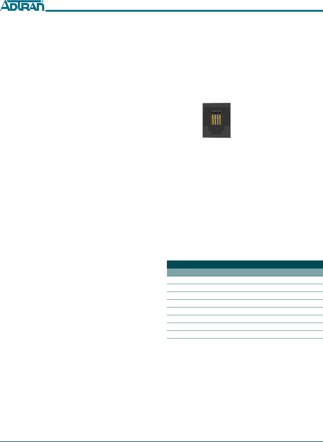
3. Refer to the illustration below and connect the twisted-pair
Tip (green) and Ring (Red) to the RJ-11 connectors using an
RJ-11 crimper.
4. Connect one end of the POTS cable to the Home Gateway
ONT and the other end to a standard telephone connection.
Step 3: Connect Ethernet
The Home Gateway ONT supports four Gigabit (10/100/
1000Base-T) connections. To install Ethernet to the Home
Gateway ONT, refer to the illustration on the first page and
complete the following steps:
1. Remove the Ethernet cable supplied with the Home Gate-
way ONT and attach one end to the LAN1 connection on the
rear of the Home Gateway ONT and the other end to the
incoming Ethernet device.
2. If an Ethernet cable is not available, obtain a CAT5 or 6 cable
of appropriate length and trim the insulation back
approximately 1/2 inch on both ends.
3. Connect the wires per to an RJ-45 connector using the table
below.
4. Crimp the connector using an RJ-45 Crimper.
5. Connect one end to the appropriate LAN1 connection on the
rear of the Home Gateway ONT and the other end to the
incoming Ethernet device.
6. Repeat these steps as necessary for each additional Ethernet
connection required.
Ethernet RJ-45 Pin-out
Pin Name Description ColorCode
1 TRD0+ Transmit/ReceivePositive White/Orange
2TRD0‐Transmit/ReceiveNegative Orange
3 TRD1+ Transmit/ReceivePositive White/Green
4 TRD2+ Transmit/ReceivePositive Blue
5TRD2‐Transmit/ReceiveNegative White/Blue
6TRD1‐Transmit/ReceiveNegative Green
7 TRD3+ Transmit/ReceivePositive White/Brown
8TRD3‐Transmit/ReceiveNegative Brown
1 2 3 4
1 = Not Connected
2 = Tip
3 = Ring
4 = Not connected
POTS Pin-Outs
Installation Overview
To install the Home Gateway ONT, complete the following steps:
Step 1: Install Home Gateway ONT
Step 2: Connect POTS
Step 3: Connect Ethernet
Step 4: Connect Fiber
Step 5: Connect Power
Step 6: Connect USB
Required tools
Standard technician tools and those listed below are required for
installing the Home Gateway ONT:
3/32 inch screw driver for connecting Home Gateway ONT
power
RJ-45/RJ-11 crimper
A telephony/data communication test set
PON power meter with wavelength filtering
Fiberscope or videoscope
Two #8 Pan Head screws (1 inch or greater in length)
Assorted tie wraps for securing cabling and wiring
For fiber optic connections, the following are required:
Fiber optical fusion splice tools
ODC Fiber cleaning tool
SC Fiber connector
Installation Steps
To install the Home Gateway ONT, refer to the illustration on the
first page and complete the following steps.
Step 1: Install the Home Gateway ONT
There are two options when installing the Home Gateway ONT:
Desk Top and Wall Mount. Both are described below.
Desk Top Installation
The Home Gateway ONT can sit on a desktop or be wall
mounted. With a desk mount, ensure the Home Gateway ONT is
not located in direct sunlight and is not located next to any
thermal obstructions.
Wall Mount Installation
To wall mount the Home Gateway ONT, perform the following
steps:
1. Decide on a location for the Home Gateway ONT. Included
with the Home Gateway ONT is a 12 V Power Adaptor with
a 4-foot power cord. The installation location should be
within 4 feet of a wall outlet.
2. Remove the Mounting Bracket from the bottom of the Home
Gateway ONT.
3. Use the keyhole slots on the back of the Mounting Bracket as
a template and attach it to drywall using the appropriate
anchors.
4. Reattach the Home Gateway ONT to the Mounting Bracket.
Step 2: Connect POTS
To connect POTS, refer to the illustration on the first page and
perform the following steps:
DRAFT

61287562G1-22A 3
Step 4: Connect Fiber
CAUTION
C
LASER RADIATION
1310 nm to 1600 nm
Do not view directly with optical instruments.
This product contains a Class 1M Laser module that complies with 21 CFR
1040.10 and 1040.11 and IEC 60825-1 and -2.
Fiber is installed using an SC connecter attached to the OPTICAL
Interface on the rear of the Home Gateway ONT. Refer to the
illustration on the first page and complete the following steps to
connect fiber:
1. Remove the protective cover from the OPTICAL Interface.
NOTE
The protective cover should always be inserted in the optical
interface when the Fiber connection is not in use. This will help
protect the optical components.
2. Clean the ends of the SC connector and the surface of the
OPTICAL Interface using appropriate fiber cleaning
methods.
3. Connect the incoming fiber cable to the SC connection.
4. Route the fiber cable so that it is protected from accidental
harm.
Step 5: Connect Power
To connect power to the Home Gateway ONT, refer to the illus-
tration on the first page and complete the following steps:
1. Plug the supplied 12V AC/DC Power Converter into the
PWR connection on the rear of the Home Gateway ONT.
2. Connect the power plug to a standard 120V AC outlet.
3. Verify the power is on by checking the PWR LED on the
Home Gateway ONT. The LED should be green indicating
local power is on and voltage is good.
ON/OFF Button
An On/Off button is located on the far-right side of the rear of the
Home Gateway ONT. User functionality is limited to this button.
NOTE
If a Battery Backup (BBU) is being used and is disconnected, the
Home Gateway ONT is not protected from power outages, and
will send a “Battery Missing” alarm to the OLT.
Step 6: Connect USB
The Home Gateway ONT is equipped with a USB port. Refer to
the illustration on the first page for the location of this connection.
LED STATUS
The LEDs are located beneath the plastic housing and are only
visible after power has been applied. The following table provides
the LED status during normal operations.
*ONU. An Optical Network Unit (ONU) is a device that transforms incoming optical
signals into electronic signals at a customer’s premises.
Label Status Indication
PWR
Off
Green
ONT power is Off
ONT power On
LINK
2
Off
Green
Green Flashing
ONT is not active (not Ranged)
ONT is active (Ranged)
ONT is activating (Ranging in
progress)
AUTH
2
Off
Green
Green Flashing
ONU* is NOT authorized
ONU is authorized
ONU is registering
LAN1 -4
2
Off
Green
Green Flashing
Link is down
LAN Port is up
LAN Port is actively transmit-
ting and receiving
TEL1 - 2
2
Off
Green
Green Flashing
ONT is not registered
ONT is registered and on hook
Off hook or call in progress
INTER-
NET
2
Off
Green
Green Flashing
WAN not configured
Internet is connected
Internet is connecting
WPS
2
2
Off
Green
Yellow Flashing
Red Flashing
WPS is disabled
WPS status is “Successful”
WPS status is “in Progress”
WPS is experiencing errors
WLAN
2
Off
Green
Green Flashing
Error/WLAN is not connected
WLAN is connected
WLAN receiving/transmitting
data
USB
2
Off
Green
Green Flashing
No power or USP not con-
nected
USP connected
USP receiving/transmitting
data
DRAFT

TROUBLESHOOTING
The following table can be used for troubleshooting purposes:
SPECIFICATIONS
Refer to the following for a list of all specifications for the Indoor
Home Gateway ONT.
Electrical
oVoltage: 12 Volts typical
oMinimum Voltage: 10 Volts
oMaximum Voltage: 13.9 Volts
oPower Consumption: Typical 13.9 watts
Physical
o10.0 inches wide (19.5 centimeters)
o5.9 inches deep ((18.8 centimeters)
o 1.5 inches high (3.3 centimeters no bracket, 5.1 with bracket)
oWeight: 2 pounds (0.9 kilograms)
Environmental
oOperational Temperature: 32°F to +113°F (0°C to +50°C)
oStorage Temperature: –40°F to 185°F (–20°C to +50°C)
oRelative Humidity: 90%, noncondensing
Problem Possible Solution
The Power LED is Off Verify that the power adapter is
plugged into a live AC outlet.
Check that he ON/OFF button
is pressed in.
Check the power cable for shorts
or breaks.
Disconnect the power input con-
nector at the ONT and use a volt-
meter to verify that the proper
voltage level is present on the 12
V pin (power and power return)
from the power adapter.
The LINK LED is Off Check that the optical fiber is
connected correctly.
Check the optical connector for
dirt or damage.
LINK LED is ON, but
INTERNET LED is Off
The signal sent by the service
provider is not being received.
Contact the service provider for
assistance.
The LAN LED is Off Check that the Ethernet cable is
connected correctly.
Check that the network adaptor
works normally. Refer to the doc-
umentation that accompanied
the network adapter as needed.
Optical
oTX min power: 0.5 dBm
oTX max power: 5.0 dBm
oRSSI max sensitivity: -27 dBm
oRX overload: -8 dBm
oTX wavelength: 1310 nm typical
oRX wavelength: 1490 nm typical
MAINTENANCE
The Indoor 2 POTS + 4GigE does not require routine hardware
maintenance for normal operation. ADTRAN does not
recommend that repairs be attempted in the field. Repair services
may be obtained by returning the defective unit to ADTRAN.
Refer to the warranty for further information. Field support for
software is provided through upgrade facilities.
SAFETY AND REGULATORY COMPLIANCE
Refer to the Total Access 324RG Indoor 2 POTS + 4GigE Safety and
Regulatory Compliance Notice (61287562G1-17) for detailed safety
and regulatory information.
DRAFT
61287562G1-22A 4

Le présent appareil est conforme aux CNR d'Industrie Canada applicables aux appareils radio exempts de licence.
L'exploitation est autorisée aux deux conditions suivantes : (1) l'appareil ne doit pas produire de brouillage, et (2)
l'utilisateur de l'appareil doit accepter tout brouillage radioélectrique subi, même si le brouillage est susceptible
d'en compromettre le fonctionnement.
Changes or modifications not expressly approved by the party responsible for compliance could void the user's
authority to operate the equipment.
This equipment has been tested and found to comply with the limits for a Class B digital device, pursuant to part 15
of the FCC Rules. These limits are designed to provide reasonable protection against harmful interference in a
residential installation. This equipment generates uses and can radiate radio frequency energy and, if not installed
and used in accordance with the instructions, may cause harmful interference to radio communications. However,
there is no guarantee that interference will not occur in a particular installation. If this equipment does cause
harmful interference to radio or television reception, which can be determined by turning the equipment off and on,
the user is encouraged to try to correct the interference by one or more of the following measures:
-Reorient or relocate the receiving antenna.
-Increase the separation between the equipment and receiver.
-Connect the equipment into an outlet on a circuit different from that
to which the receiver is connected.
-Consult the dealer or an experienced radio/TV technician for help.
Under Industry Canada regulations, this radio transmitter may only operate using an antenna of a type and maximum
(or lesser) gain approved for the transmitter by Industry Canada. To reduce potential radio interference to other users,
the antenna type and its gain should be so chosen that the equivalent isotropically radiated power (e.i.r.p.) is not more
than that necessary for successful communication.
Conformément à la réglementation d'Industrie Canada, le présent émetteur radio peutfonctionner avec une antenne d'un
type et d'un gain maximal (ou inférieur) approuvé pour l'émetteur par Industrie Canada. Dans le but de réduire les risques
de brouillage radioélectrique à l'intention des autres utilisateurs, il faut choisir le type d'antenne et son gain de sorte que la
puissance isotrope rayonnée équivalente (p.i.r.e.) ne dépasse pas l'intensité nécessaire à l'établissement d'une communication
satisfaisante.
MPE Reminding
To satisfy FCC / IC RF exposure requirements, a separation distance of 20 cm or more should be maintained between
the antenna of this device and persons during device operation. To ensure compliance, operations at closer than
this distance is not recommended.
Les antennes installées doivent être situées de facon à ce que la population ne puisse y être exposée à une distance de moin
de 20 cm. Installer les antennes de facon à ce que le personnel ne puisse approcher à 20 cm ou moins de la position centrale
de l' antenne. La FCC des éltats-unis stipule que cet appareil doit être en tout temps éloigné d'au moins 20 cm des personnes
pendant son functionnement.
Region Selection
Limited by local law regulations, version for North America does not have region selection option.
CAUTION!
SUBJECT TO ELECTROSTATIC DAMAGE
OR DECREASE IN RELIABILITY
HANDLING PRECAUTIONS REQUIRED
Warranty: ADTRAN will replace or repair this product within the warranty period if it does not
meet its published specifications or fails while in service. Warranty information can be
found online at www.adtran.com/warranty.
©2014 ADTRAN, Inc. All Rights Reserved.
ADTRAN CUSTOMER CARE:
From within the U.S. 1.800.726.8663
From outside the U.S. +1 256.963.8716
PRICING AND AVAILABILITY 1.800.827.0807
*61287562G1-22A*