ADTRAN AG10W ADSL 2+ WIRELESS 4 PORT ROUTER User Manual AG10W Manual 1225
SmartRG, Inc. ADSL 2+ WIRELESS 4 PORT ROUTER AG10W Manual 1225
ADTRAN >
User manual revised 3
AG10W
ADSL 2+ WIRELESS 4 PORT ROUTER
User’s Manual
Version 1.0
Copyright © 2005 by TECOM CO., LTD.
TECOM CO., LTD.
23, R&D ROAD 2
SCIENCE-BASED INDUSTRIAL PARK
HSIN-CHU TAIWAN R.O.C.

Manual Ver1.0
- 2 -
Table of Contents
1. INTRODUCTION..................................................................................................................................................... 4
1.1 FEATURES.........................................................................................................................................................4
1.2 SYSTEM REQUIREMENTS .................................................................................................................................. 4
2. INSTALLATION....................................................................................................................................................... 5
FRONT PANEL .................................................................................................................................................................5
REAR PANEL ................................................................................................................................................................... 5
CONNECTING THE HARDWARE........................................................................................................................................ 6
Step 1. Connect the ADSL cable and optional telephone....................................................... 6
Step 2. Connect the Ethernet cable...................................................................................................... 6
Step 3. Attach the power connector..................................................................................................... 6
Step 4. Turn on AG10W and power up your systems ................................................................ 7
Step 5. Configure AG10W through the WEB interface ............................................................ 7
Step 6. Save the configurations and Reboot................................................................................... 7
3. CONFIGURATION .................................................................................................................................................. 8
3.1 SETUP ............................................................................................................................................................... 8
3.2 ESTABLISH THE CONNECTION ..........................................................................................................................8
4. QUICK SETUP ....................................................................................................................................................... 10
4.1 PPP OVER ETHERNET (PPPOE) CONFIGURATION............................................................................................ 10
4.2 IP OVER ATM (IPOA) CONFIGURATION.......................................................................................................... 15
4.3 BRIDGE CONFIGURATION................................................................................................................................ 20
4.4 MAC ENCAPSULATION ROUTING (MER) CONFIGURATION ............................................................................ 23
4.5 PPP OVER ATM (PPPOA) CONFIGURATION.................................................................................................... 24
5. ADVANCED SETUP............................................................................................................................................... 25
5.1 WAN.............................................................................................................................................................. 25
5.2 LAN............................................................................................................................................................... 25
5.3 NAT ............................................................................................................................................................... 25
5.4 FIREWALL....................................................................................................................................................... 29
5.5 QUALITY OF SERVICE ..................................................................................................................................... 33
5.6 ROUTING ........................................................................................................................................................ 34
5.7 DNS............................................................................................................................................................... 36
6. WIRELESS SETUP ................................................................................................................................................ 39
6.1 BASIC ............................................................................................................................................................. 39

Manual Ver1.0
- 3 -
6.2 SECURITY ....................................................................................................................................................... 39
6.3 MAC FILTER .................................................................................................................................................. 43
6.4 WIRELESS BRIDGE.......................................................................................................................................... 43
6.5 ADVANCED ..................................................................................................................................................... 44
6.6 STATION INFO ................................................................................................................................................. 46
7. DIAGNOSTICS....................................................................................................................................................... 47
8. MANAGEMENT..................................................................................................................................................... 48
8.1 SETTINGS........................................................................................................................................................ 48
8.2 SYSTEM LOG .................................................................................................................................................. 50
8.3 SNMP AGENT ................................................................................................................................................ 51
8.4 INTERNET TIME .............................................................................................................................................. 52
8.5 ACCESS CONTROL .......................................................................................................................................... 52
8.6 UPDATE SOFTWARE ........................................................................................................................................ 54
8.7 SAVE/REBOOT ................................................................................................................................................ 55
9. DEVICE INFO ........................................................................................................................................................ 56
9.1 SUMMARY ...................................................................................................................................................... 56
9.2 WAN.............................................................................................................................................................. 56
9.3 STATISTICS...................................................................................................................................................... 56
9.4 ROUTE............................................................................................................................................................ 59
9.5 ARP ............................................................................................................................................................... 59

Manual Ver1.0
- 4 -
1. Introduction
Congratulations on becoming the owner of AG10W 4-port ADSL AP router. You will now be
able to access the Internet using your high-speed ADSL connection. AG10W has the following
major features.
1.1 Features
• Built-in ADSL modem for high speed Internet access
• Network Address Translation (NAT) and IP filtering functions to provide
network sharing and firewall protection for your computers
• 4-port switch to build your own local network
• Easy configuration via a web browser
• IEEE 802.11g 54Mbps Access Point
This User’s Manual will guide you to install and configure your AG10W.
1.2 System Requirements
Before installing your AG10W, make sure that you have the following:
• ADSL service up and running on your telephone line, with at least one public Internet
address for your LAN
• One or more computers each containing an Ethernet 10Base-T/100Base-T network
interface card (NIC) or wireless network adapter.
For system configuration, use the supplied web-based program.
Note: Make sure that your computer has a web browser such as Internet Explorer v5.0 or
later, or Netscape v4.7 or later.

Manual Ver1.0
- 5 -
2. Installation
In addition to this document, your AG10W should arrive with the following:
• One standalone desktop AG10W
• One power adapter and power cord
• One Ethernet cable with RJ-45 connector
• One telephone cable with RJ-11 connector
Front Panel
The front panel LEDs indicate the status of the unit.
Label Color Function
PWR Green On: Power on
Off: Power off
LAN1~4 Green On: LAN link established and active
Off: No LAN link
Flashes during data transfer
DSL Green Flashes during the training mode.
On: ADSL link established and active
Tx/Rx Green On: Router is active
Flashes during data transfer through ADSL line
WLAN Green On: WLAN enabled
Off: WLAN disabled
Flashes during data transfer
Rear Panel
The connectors located at the rear panel have the following functions.
Interface Function
Botton Power switch on/off
Power (SNG 1- tec) Connects to the power adapter cable
Reset Resets unit’s configuration to factory default
LAN1~4 RJ-45 connector: Connects AG10W to your PC's
Ethernet port, or to the uplink port on your LAN's hub
ADSL RJ-11 connector: Connects AG10W to ADSL line

Manual Ver1.0
- 6 -
Figure 1. Rear view of AG10W
Connecting the Hardware
Connect AG10W to the phone jack, the power outlet, and your computer or network.
WARNING
Before you begin, turn the power off for all devices. These include your
computer(s), your LAN hub/switch (if applicable), and AG10W.
Step 1. Connect the ADSL cable and optional telephone
Connect one end of the phone cable to the RJ-11 connector on the rear panel of AG10W. Connect
the other end to the ADSL outlet provided by your service provider (normally MODEM port of the
attached splitter).
Step 2. Connect the Ethernet cable
Connect one end of the Ethernet cable to the one of the four RJ-45 connectors on the rear panel of
AG10W and connect the other end to your PC’s network adaptor (NIC). If you are connecting a
LAN to AG10W, attach one end of the Ethernet cable to a regular hub port and the other end to the
LAN port on AG10W.
Step 3. Attach the power connector
Connect the AC power adapter to the power connector on AG10W and plug in the adapter to a wall
outlet or power extension.

Manual Ver1.0
- 7 -
Step 4. Turn on AG10W and power up your systems
Press the Power switch on the back panel of AG10W to the ON (Low) position.
Turn on and boot up your computer(s) and any LAN devices such as hubs or switches.
Step 5. Configure AG10W through the WEB interface
Please refer to chapter 3.
Step 6. Save the configurations and Reboot
Save the changes you made on AG10W.
Manual Ver1.0
- 8 -
3. Configuration
3.1 Setup
Connect AG10W and PC with an RJ-45 Ethernet cable.
Turn on AG10W.
The default IP address of AG10W is 192.168.1.1.
3.2 Establish The Connection
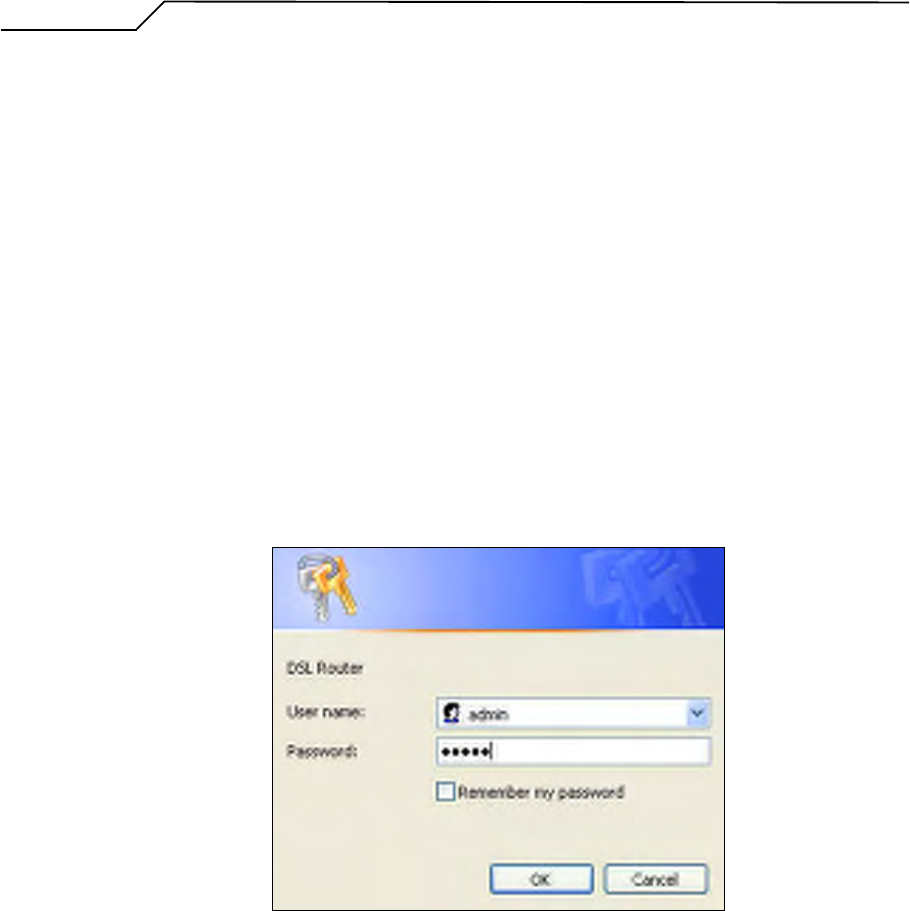
Enter the IP address (default: 192.168.1.1) of AG10W in the address line of Web
Browser
A Dialogue Box will pop up to request the user to login. (Figure 1)
Figure 2. Authentication
Please enter the management username/password into the fields then click on the
OK button (default username/password is admin/admin).
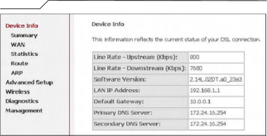
If the authentication is valid, the home page “Device Info - Summary” will be
displayed on the screen. (Figure 3)
Manual Ver1.0
- 9 -
Figure 3. AG10W Home Page
Manual Ver1.0
- 10 -
4. Quick Setup
The system administrator can configure AG10W remotely or locally via a Web
Browser. Network configuration needs to be planned and decided before starting the
configuration procedure.
Quick Setup allows system administrator to select the appropriate operation mode and
configure the corresponding settings step by step to create a connection. The following
five operation modes are supported:
PPP over Ethernet (PPPoE)
IP over ATM (IPoA)
Bridging
MAC Encapsulation Routing (MER)
PPP over ATM (PPPoA)
4.1 PPP over Ethernet (PPPoE) Configuration
Click on “Quick Setup” in the left frame, and follow the steps below to create a PPP
over Ethernet (PPPoE) connection.
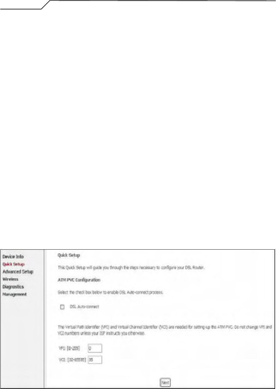
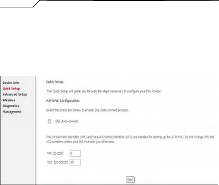
4.1.1 ATM PVC Configuration
Figure 4. Quick Setup – ATM PVC Configuration
Manual Ver1.0
- 11 -
Enter the VPI/VCI values. Please contact you ISP for the information.
Click on “Next” to go to next step.
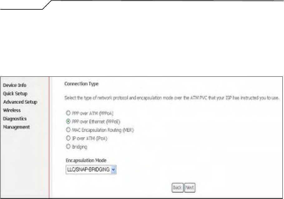
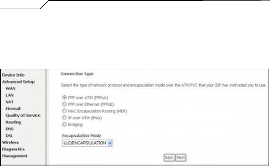
4.1.2 Connection Type and Encapsulation Mode
Figure 5. Quick Setup – Connection Type and Encapsulation Mode
Select “PPP over Ethernet (PPPoE)”, and the “Encapsulation Mode”. Please
contact you ISP for the information.
Click on “Next” to go to next step.
4.1.3 PPP Username and Password
Manual Ver1.0
- 12 -
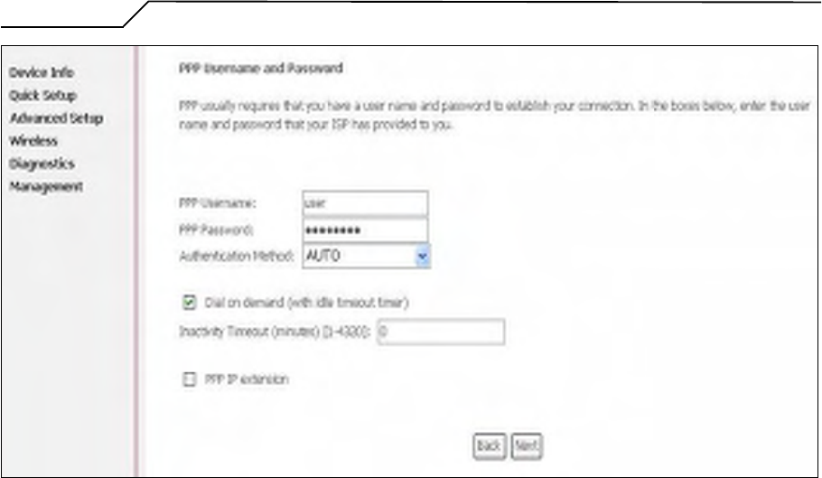
Figure 6. Quick Setup – PPP Username and Password
Enter “PPP Username”, “PPP Password”, and select “Authentication Method”
(AUTO/PAP/CHAP). Please contact you ISP for the information.
The “Dial on demand” function, if checked, will tear down the PPP link
automatically when there is no outgoing packet for the programmed period of time
that is set below.
AG10W activates PPPoE connection automatically when user wants to access
Internet and there is no active PPPoE connection.
The users are able to assign some specific ATM PVC(s) to run PPPoE, if AG10W
has multiple ATM PVC connections.
The “PPP IP extension” is a special feature provided by some ISPs. Unless your
service provider specifically requires this setup, do not select it.
Click on “Next” to go to next step.
4.1.4 IGMP Multicast, WAN service, and QoS
Manual Ver1.0
- 13 -
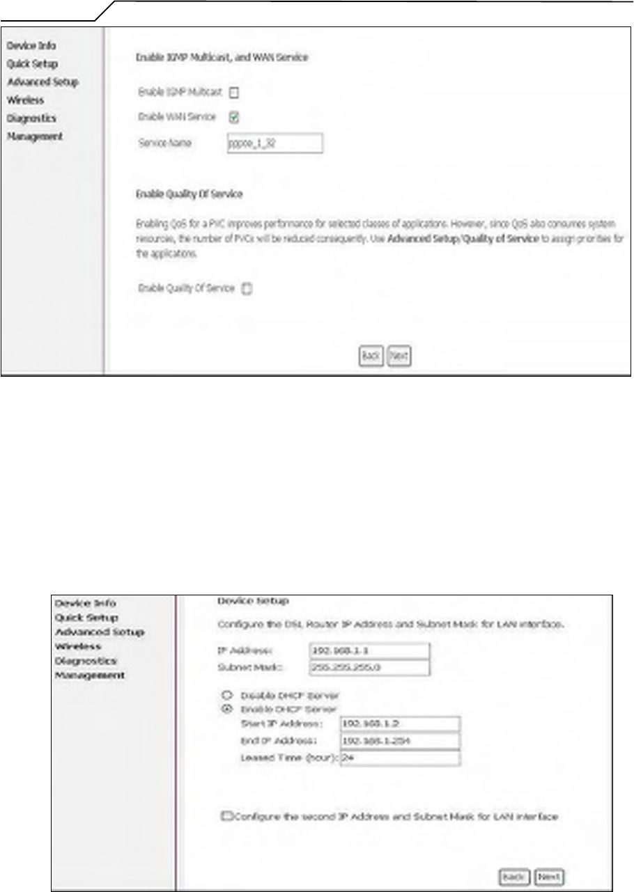
Figure 7. Quick Setup – IGMP Multicast, WAN service, and QoS
Check to Disable/Enable IGMP Multicast, WAN Service, and QoS.
Go to “Advanced Setup” > “Quality of Service” to assign priorities for the
application. Click on “Next” to go to next step.
4.1.5 Device Setup
Figure 8. Quick Setup – Device Setup
Manual Ver1.0
- 14 -
Enter IP (LAN IP) and Subnet Mask.
Select to Disable/Enable DHCP Server, use DHCP Server Relay, and configure
related settings for that mode.
AG10W will assign IP address, subnet mask, Default gateway IP address and DNS
server IP address to host PCs which connect to its LAN.
Select “Configure the second IP Address and Subnet Mask for LAN interface” and
configure if second IP Address is used.
Note: Network Address Translation function (NAT) is default enabled and is not
showing on the page to prevent it from being disabled.
Click on “Next” to go to next step.
4.1.6 Wireless Setup
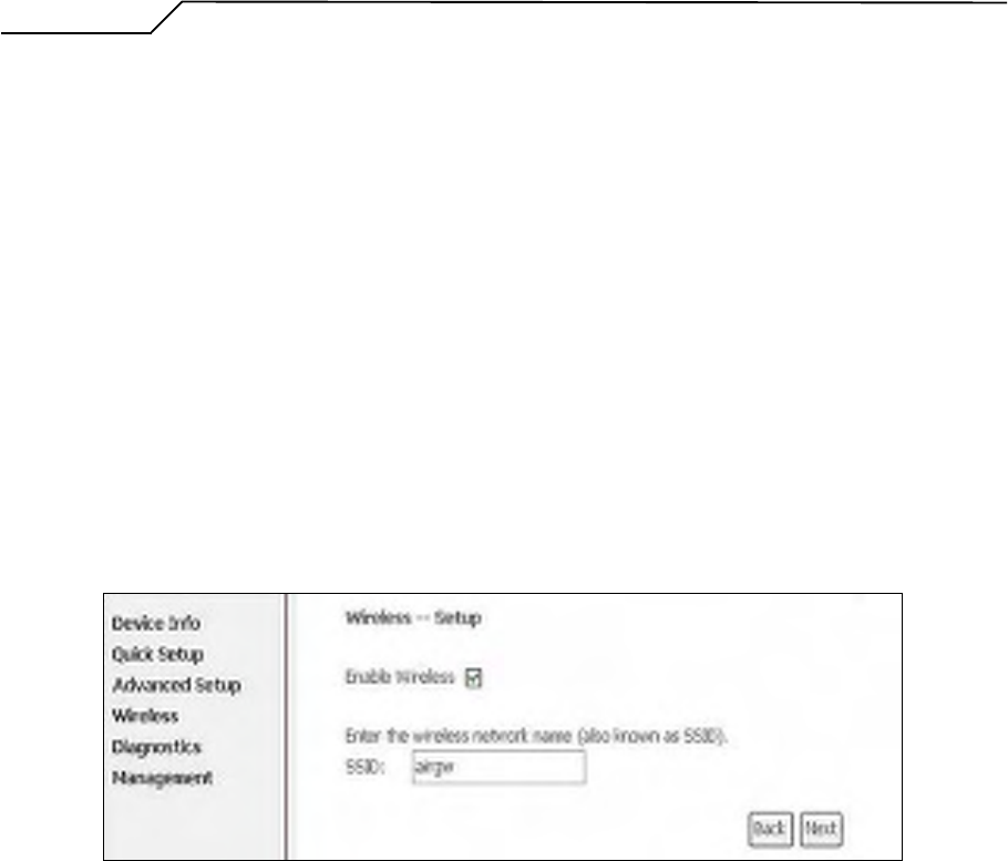
Figure 9. Quick Setup - Wireless Setup
Check “Enable Wireless” to enable wireless radio; or uncheck to disable.
“SSID” is the network name shared among all devices in a wireless network. It is
case-sensitive and must not exceed 32 alphanumeric characters.
Click on “Next” to go to next step.
4.1.7 WAN Setup – Summary
Manual Ver1.0
- 15 -
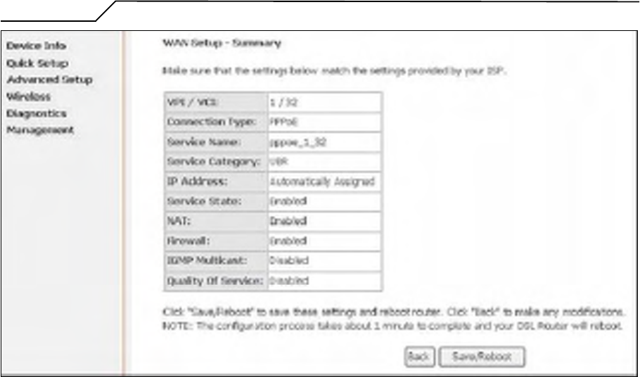
Figure 10. Quick Setup – WAN Setup – Summary
The last page displays a summary of previous settings. Make sure that the
configurations match the settings provided by ISP, and then click on
“Save/Reboot” button to complete the configuration procedure.
4.2 IP over ATM (IPoA) Configuration
Click on “Quick Setup” in the left frame, and follow the steps below to create an IP
over ATM (Routed) connection.
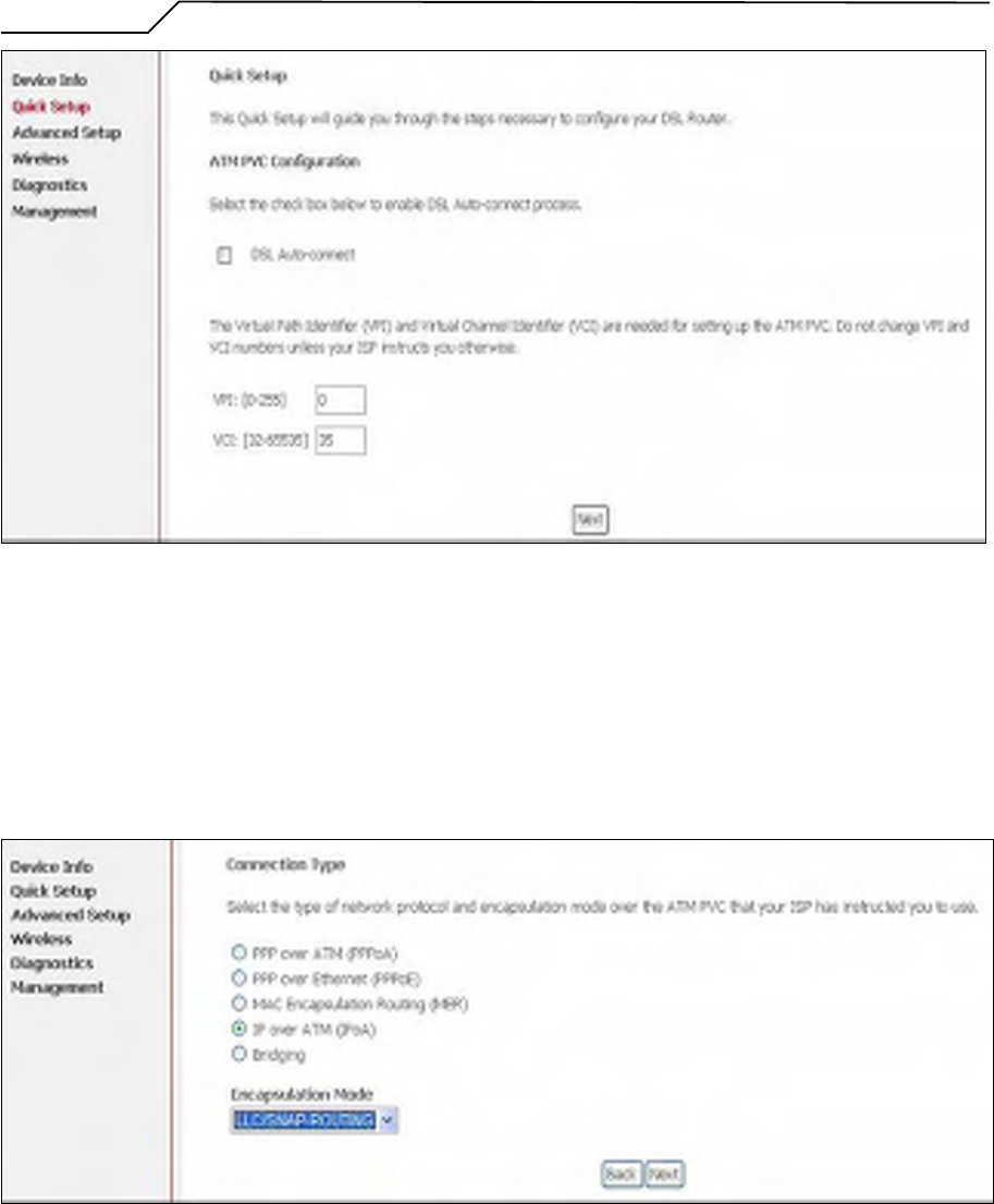
4.2.1 ATM PVC Configuration
Manual Ver1.0
- 16 -
Figure 11. Quick Setup – ATM PVC Configuration
Enter the VPI/VCI values. Please contact you ISP for the information.
Click on “Next” to go to next step.
4.2.2 Connection Type
Figure 12. Quick Setup – Connection Type and Encapsulation Mode
Select “IP over ATM (IPoA)”, and the “Encapsulation Mode”. Please contact
you ISP for the information.
Click on “Next” to go to next step.
Manual Ver1.0
- 17 -
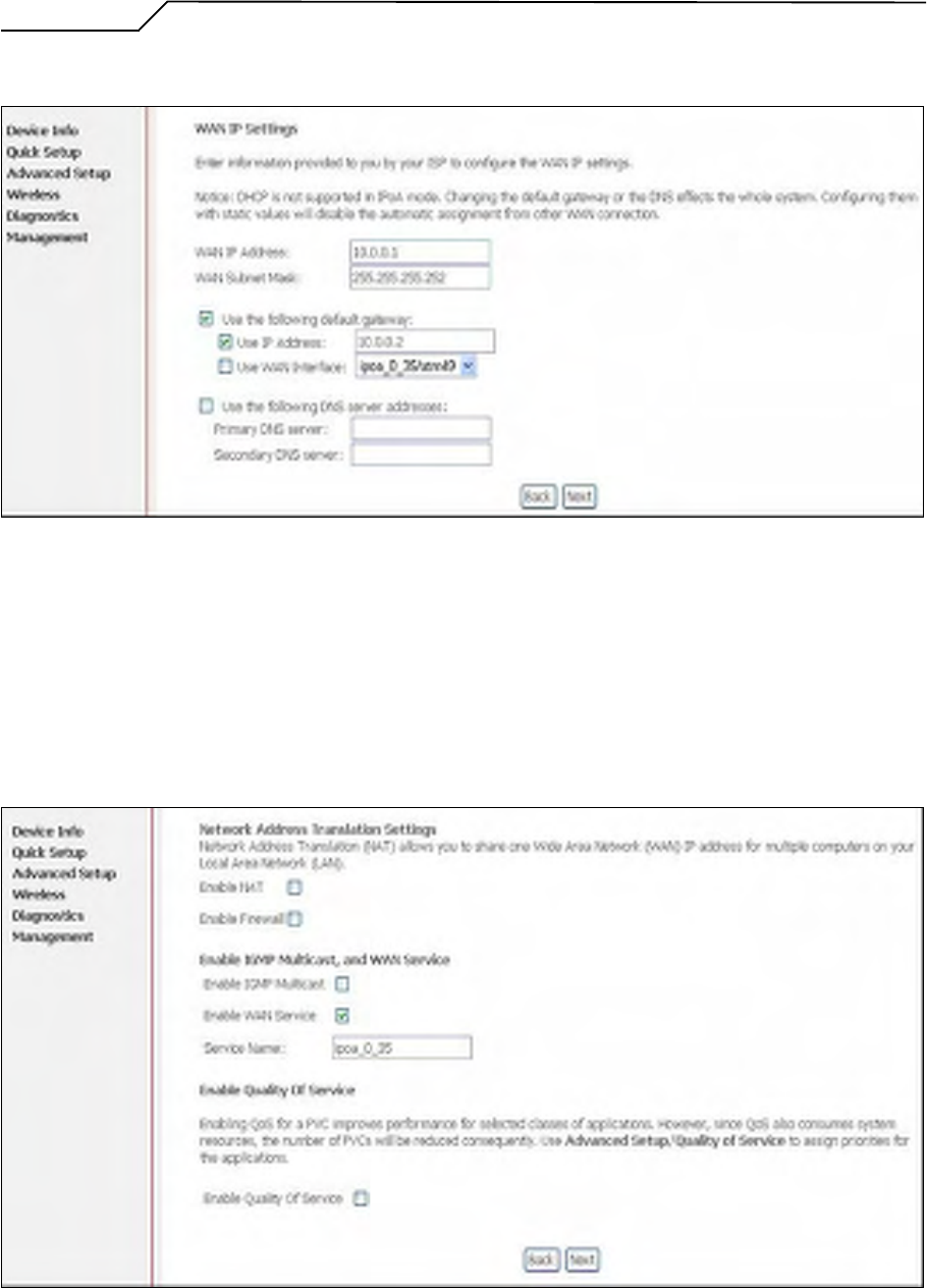
4.2.3 WAN IP Settings
Figure 13. Quick Setup– WAN IP Settings
WAN IP/Subnet Mask, default gateway, and DNS server settings. Please contact
your ISP for the information.
Click on “Next” to go to next step.
4.2.4 NAT, IGMP Multicast, WAN Service, and QoS
Figure 14. Quick Setup – IPoA – NAT, IGMP Multicast, WAN service, and QoS
Manual Ver1.0
- 18 -
Check to Enable/Disable NAT and Firewall functions.
Go to “Advanced Setup” > “Firewall” to assign filter rules.
Check to Enable/Disable IGMP Multicast, WAN Service, and QoS.
Go to “Advanced Setup” > “Quality of Service” to assign priorities for the
application.
Click on “Next” to go to next step.
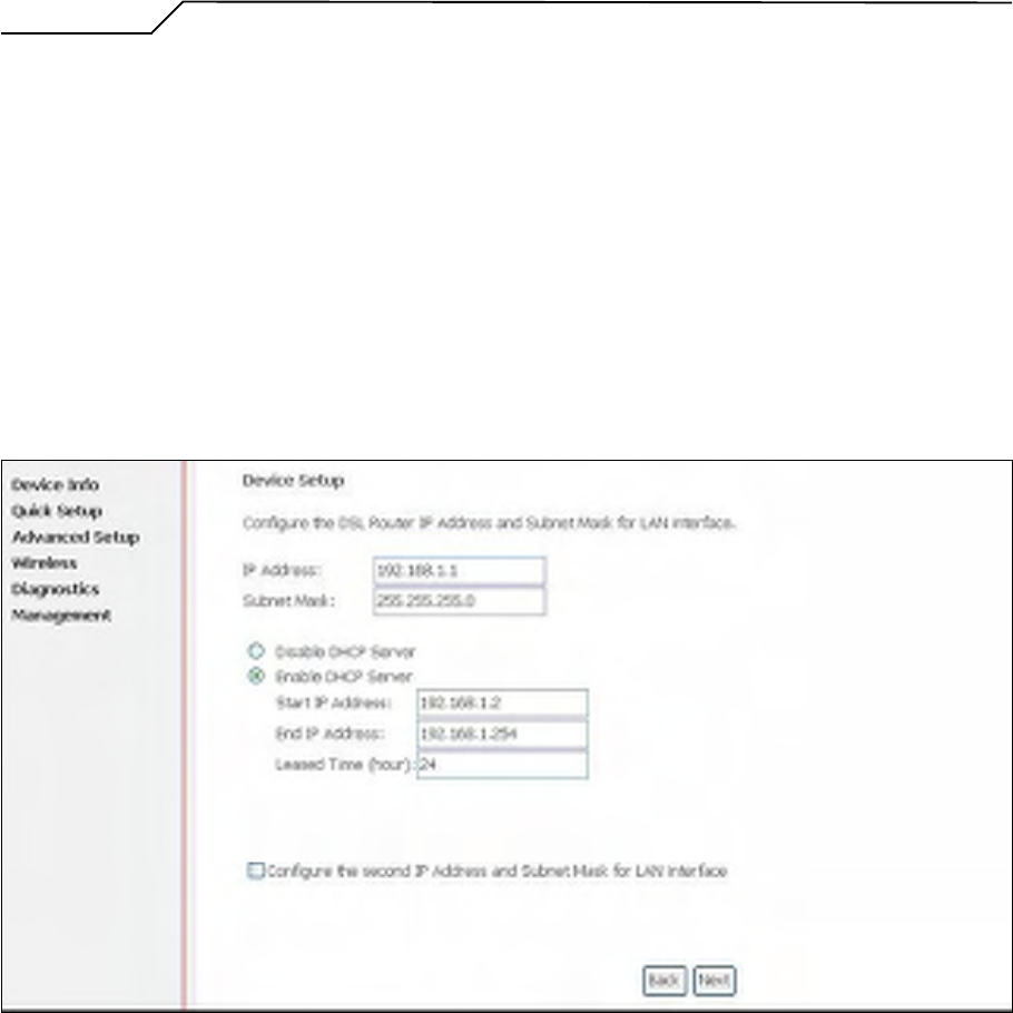
4.2.5 Device Setup
Figure 15. Quick Setup – Device Setup
Enter IP (LAN IP) Address and Subnet Mask to AG10W.
Select to Disable/Enable DHCP Server, use DHCP Server Relay, and configure
related settings for that mode.
Select “Configure the second IP Address and Subnet Mask for LAN interface” and
configure if second IP Address is used.
Click on “Next” to go to next step.
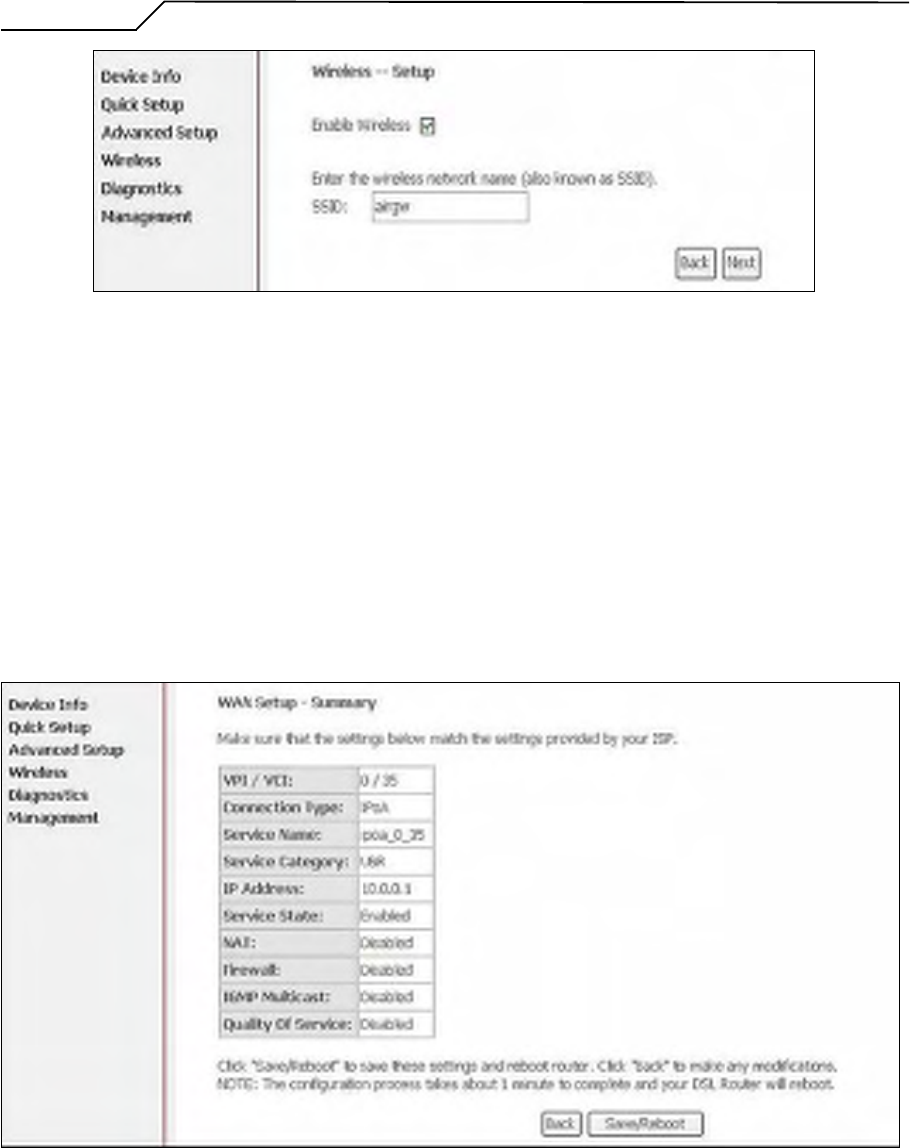
4.2.6 Wireless Setup
Manual Ver1.0
- 19 -
Figure 16. Quick Setup – Wireless Setup
Check “Enable Wireless” to enable wireless radio; or uncheck to disable.
“SSID” is the network name shared among all devices in a wireless network. It
is case-sensitive and must not exceed 32 alphanumeric characters.
Click on “Next” to go to next step.
4.2.7 WAN Setup – Summary
Figure 17. Quick Setup – WAN Setup – Summary
The last page gives a summary of previous steps. Make sure that the settings
match the settings provided by ISP, and then click on “Save/Reboot” button to
Manual Ver1.0
- 20 -
complete the configuration procedure.
4.3 Bridge Configuration
Click on “Quick Setup” in the left frame, and follow the steps below to create a
Bridging connection.
4.3.1 ATM PVC Configuration
Figure 18. Quick Setup – ATM PVC Configuration
Enter the VPI/VCI values. Please contact you ISP for the information.
Click on “Next” to go to next step.
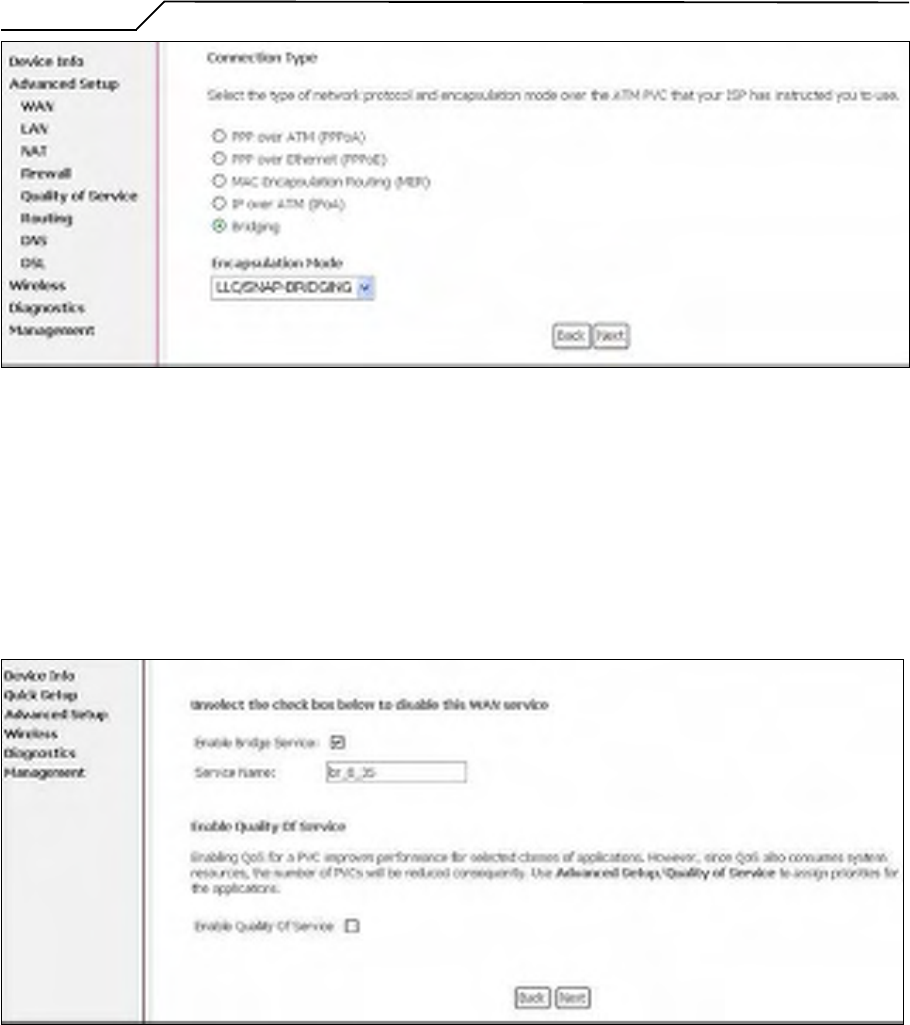
4.3.2 Connection Type
Manual Ver1.0
- 21 -
Figure 19. Quick Setup – Connection Type and Encapsulation Mode
Select “Bridging”, and the “Encapsulation Mode”. Please contact you ISP for the
information.
Click on “Next” to go to next step.
4.3.3 WAN Service
Figure 20. Quick Setup – WAN Service
Give a service name and check the box to enable this WAN service.
Check to Enable/Disable QoS.
Go to “Advanced Setup” > “Quality of Service” to assign priority for the
application.
Click on “Next” to go to next step.
Manual Ver1.0
- 22 -
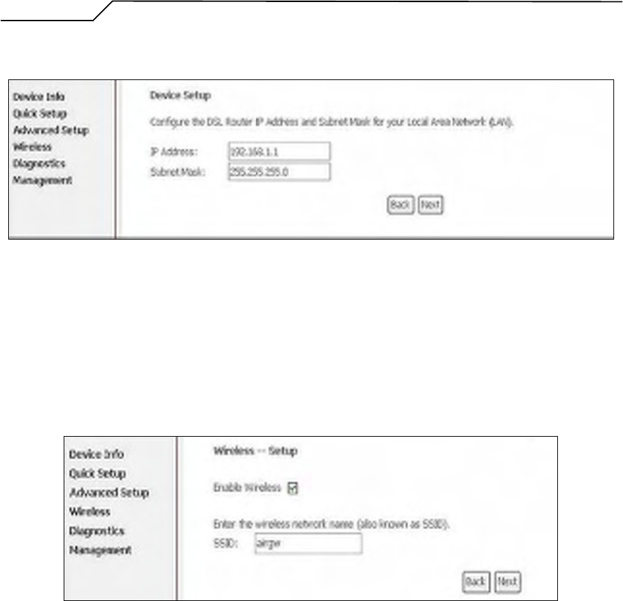
4.3.4 Device Setup
Figure 21. Quick Setup – Device Setup
Type LAN IP Address and Subnet Mask.
Click on “Next” to go to next step.
4.3.5 Wireless Setup
Figure 22. Quick Setup – Wireless Setup
Check “Enable Wireless” to enable wireless radio; or uncheck to disable.
“SSID” is the network name shared among all devices in a wireless network. It
is case-sensitive and must not exceed 32 alphanumeric characters.
Click on “Next” to go to next step.
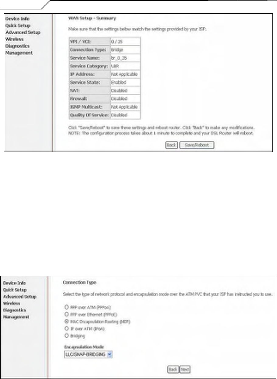
4.3.6 WAN Setup – Summary
Manual Ver1.0
- 23 -
Figure 23. Quick Setup – WAN Setup – Summary
The last page gives a summary of previous steps. Make sure that the settings
match the settings provided by ISP, and then click on “Save/Reboot” button to
complete the configuration procedure.
4.4 MAC Encapsulation Routing (MER) Configuration
Configuration of MER is similar to IPoA. Select “MAC Encapsulation Routing
(MER)” in “Connection Type”. For other configuration, please refer to IPoA settings
(section 4.2).
Figure 24. Quick Setup – Connection Type and Encapsulation Mode
Manual Ver1.0
- 24 -
4.5 PPP over ATM (PPPoA) Configuration
Configuration of PPPoA is similar to PPPoE. Select “PPP over ATM (PPPoA)” in
“Connection Type”. For other configuration, please refer to PPPoE settings (section
4.1).
Figure 25. Quick Setup – Connection Type and Encapsulation Mode
Manual Ver1.0
- 25 -
5. Advanced Setup
Advanced Setup allows system administrator to configure the following topics:
WAN
LAN
NAT
Firewall
Quality of Service
Routing
DNS
DSL
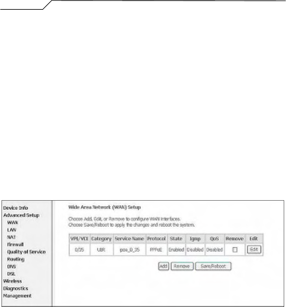
5.1 WAN
Figure 27. Advanced Setup – WAN
This page shows the current existing WAN interfaces in the system. User can choose
Add, Edit, or Remove to configure WAN interfaces. For detail about Add and Edit
procedure, please refer to 4. Quick Setup.
5.2 LAN
Please refer to 4.1.5.
5.3 NAT
Manual Ver1.0
- 26 -
Three functions are supported in NAT: Virtual Servers, Port Triggering, and DMZ
Host.
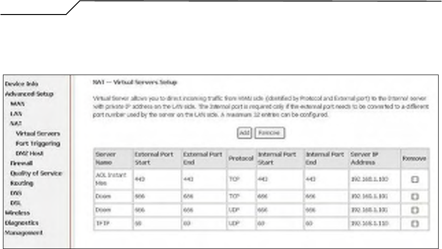
5.3.1 Virtual Servers
Figure 28. Advanced Setup – NAT
Virtual Server allows you to direct incoming traffic from WAN side (identified by
Protocol and External port) to the Internal server with private IP address on the
LAN side. The Internal port is required only if the external port needs to be
converted to a different port number used by the server on the LAN side.
Maximum 32 entries can be configured.
Click on “Add” to enter configuration page to add your own rule(s). Some
common used servers (Web, FTP, Mail, …etc.) are pre-defined in AG10W. User
can simply select the desired server from the pull-down menu and assign the IP
address of the local PC.
To delete the configured rule(s), check the “Remove” box of the specific rule(s)
and click on “Remove”.
Manual Ver1.0
- 27 -
Figure 29. Advanced Setup – NAT – Virtual Servers
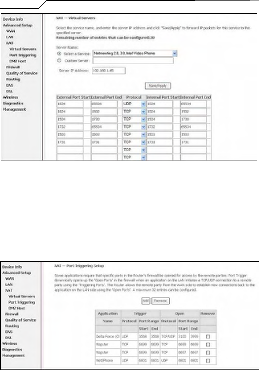
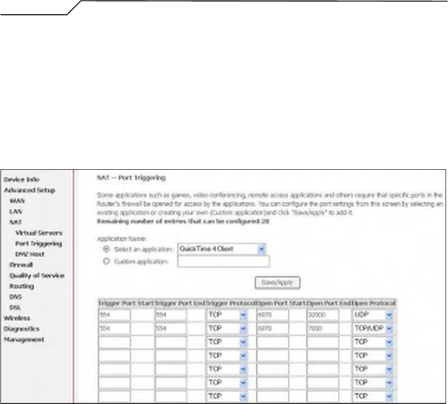
5.3.2 Port Triggering
Some applications require that specific ports in the Router's firewall be opened for
access by the remote parties. Port Trigger dynamically opens up the “Open Ports”
in the firewall when an application on the LAN initiates a TCP/UDP connection to
a remote party using the “Triggering Ports”. The Router allows the remote party
from the WAN side to establish new connections back to the application on the
LAN side using the “Open Ports”. A maximum 32 entries can be configured.
Figure 30. Advanced Setup – NAT – Port Triggering
Manual Ver1.0
- 28 -
Click on “Add” to enter configuration page to add your own rule(s). Some
applications such as games, video conferencing, remote access applications and
others require that specific ports in the Router's firewall be opened for access by
the applications. You can configure the port settings from this screen by selecting
an existing application or creating your own (Custom application) and click
“Save/Apply” to add it.
To delete the configured rule(s), check the “Remove” box of the specific rule(s)
and click on “Remove”.
Figure 31. Advanced Setup – NAT – Add Port Triggering
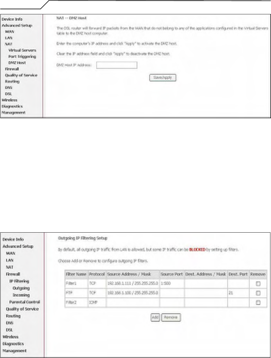
5.3.3 DMZ Host
The DSL router will forward IP packets from the WAN that do not belong to any
of the applications configured in the Virtual Servers table to the DMZ host
computer.
Enter the computer's IP address and click “Apply” to activate the DMZ host.
Clear the IP address field and click “Apply” to deactivate the DMZ host.
Manual Ver1.0
- 29 -
Figure 32. Advanced Setup – NAT – DMZ Host
5.4 Firewall
Two functions are supported in Firewall: Outgoing IP Filtering and MAC Filtering.
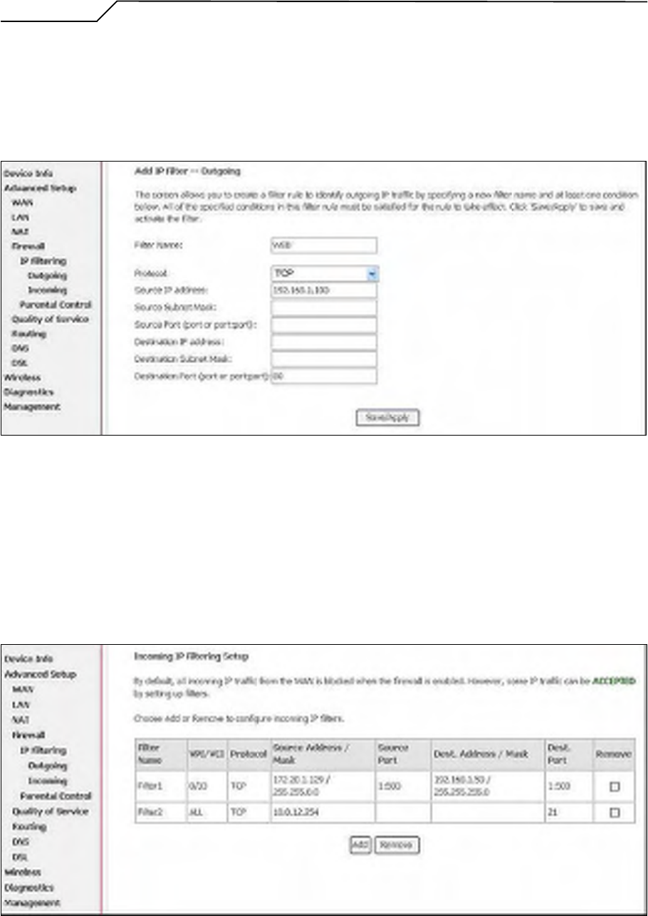
5.4.1 Firewall – Outgoing IP Filtering
By default, all outgoing IP traffic from LAN is allowed, but some IP traffic can be
BLOCKED by setting up filters. Choose “Add” to configure outgoing IP filters.
To remove, check the item and click “Remove”.
Figure 33. Advanced Setup – Firewall – Outgoing IP Filtering
The screen allows you to create a filter rule to identify outgoing IP traffic by
Manual Ver1.0
- 30 -
specifying a new filter name and at least one of the conditions below. All of the
specified conditions in this filter rule must be satisfied for the rule to take effect.
Click “Save/Apply” to save and activate the filter. Figure 34 shows the
configuration that prevents a local PC (IP address: 192.168.1.100) from surfing
the Internet.
Figure 34. Advanced Setup – Firewall – Add new Outgoing IP Filter
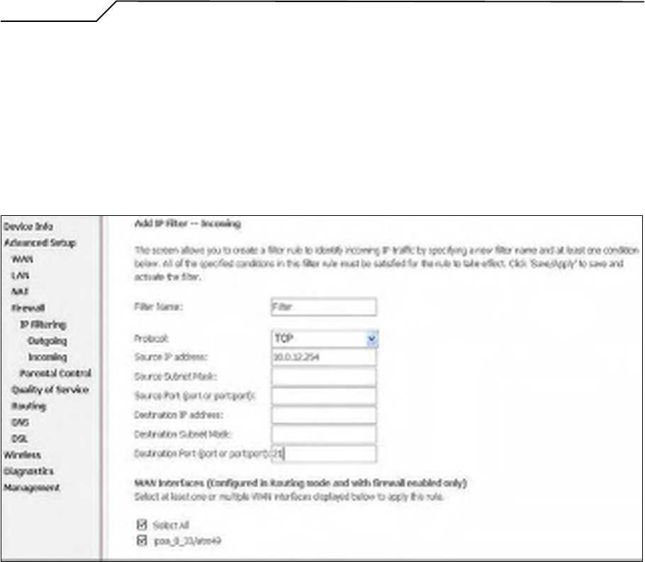
5.4.2 Firewall – Incoming IP Filtering
By default, all incoming IP traffic from the WAN is blocked when the firewall is
enabled. However, some IP traffic can be ACCEPTED by setting up filters.
Choose “Add” to configure incoming IP filters. To remove, check the item and
click “Remove”.
Figure 35. Advanced Setup – Firewall – Incoming IP Filter
Manual Ver1.0
- 31 -
The screen allows you to create a filter rule to identify incoming IP traffic by
specifying a new filter name and at least one of the conditions below. All of the
specified conditions in this filter rule must be satisfied for the rule to take effect.
Click “Save/Apply” to save and activate the filter. Figure 36 shows the
configuration that allows a remote PC (IP address: 10.0.12.254) to access the local
FTP server.
Figure 36. Advanced Setup – Firewall – Add new Incoming IP Filter
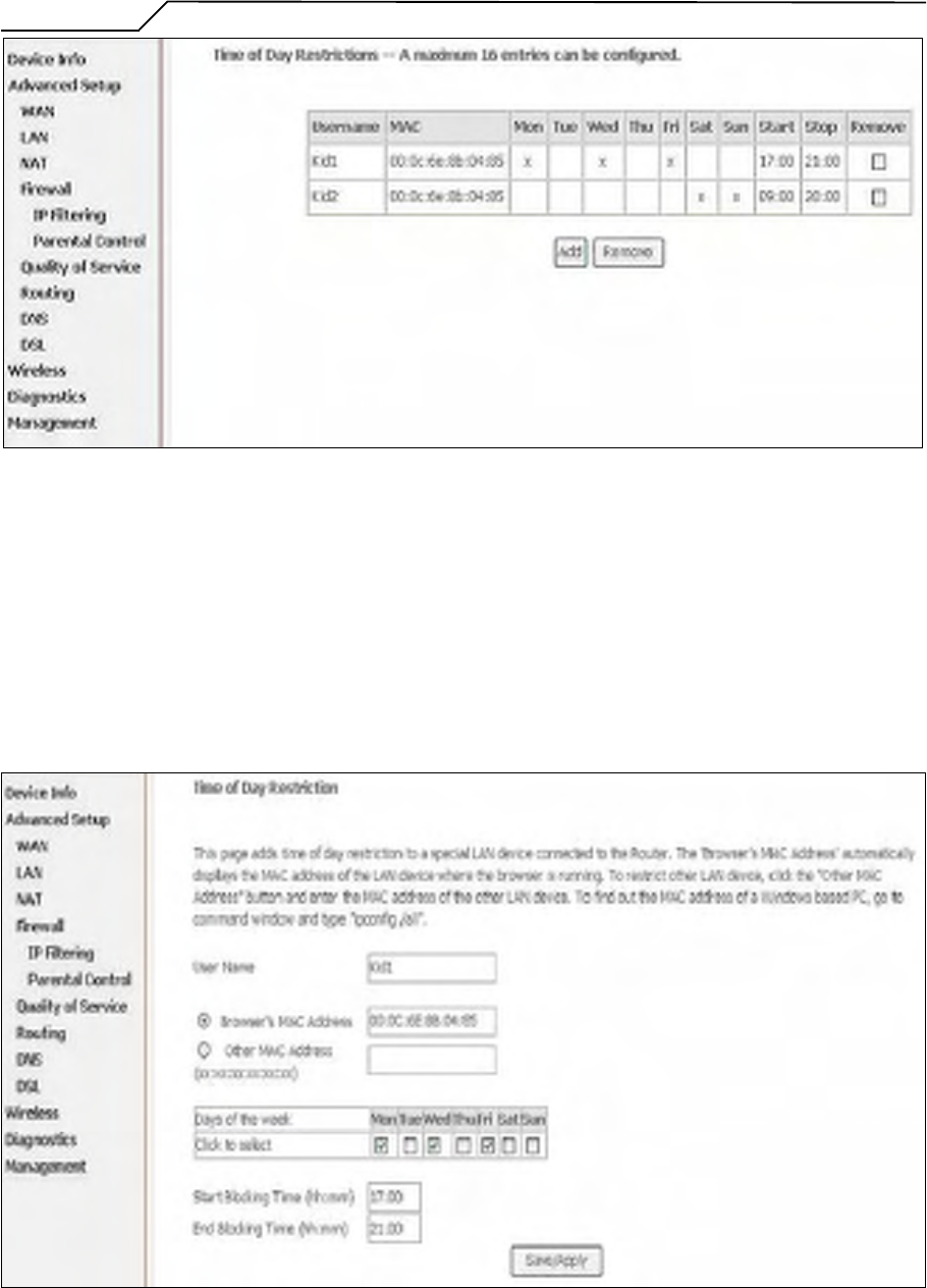
5.4.3 Firewall – Parental Control
Parental Control allows user to create time of day restriction to a special LAN
device connected to the Router. Click “Add” to configure restriction rules. To
remove, check the item and click “Remove”. Up to 16 entries can be configured
and used.
Manual Ver1.0
- 32 -
Figure 37. Advanced Setup – Firewall – Parental Control
The MAC Address of the “Browser” automatically displays the MAC address of
the LAN device where the browser is running. To restrict other LAN device, click
the “Other MAC Address” button and enter the MAC address of the other LAN
device. To find out the MAC address of a Windows-based PC, go to command
window and type “ipconfig/all”. Click “Save/Apply” to save and activate the
restriction rule.
Figure 38. Advanced Setup – Firewall – Add new Parental Control
Manual Ver1.0
- 33 -
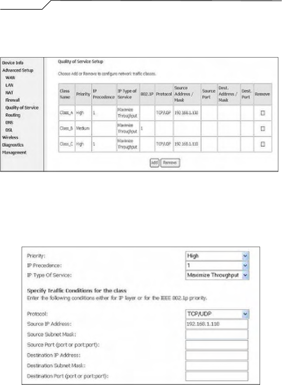
5.5 Quality of Service
Quality of Service (QoS) (including IP Precedence, IP TOS and IEEE 802.1P) refers
to a combination of mechanisms that jointly provide a specific quality level to
application traffic crossing a network or multiple, disparate networks.
Figure 39. Advanced Setup – Quality of Service
Click on “Add” to create a class to identify the IP traffic by specifying at least one
condition below. If multiple conditions are specified, all of them take effect.
Figure 40. Advanced Setup – Add new QoS rule
Manual Ver1.0
- 34 -
5.6 Routing
There are three routing information related settings.
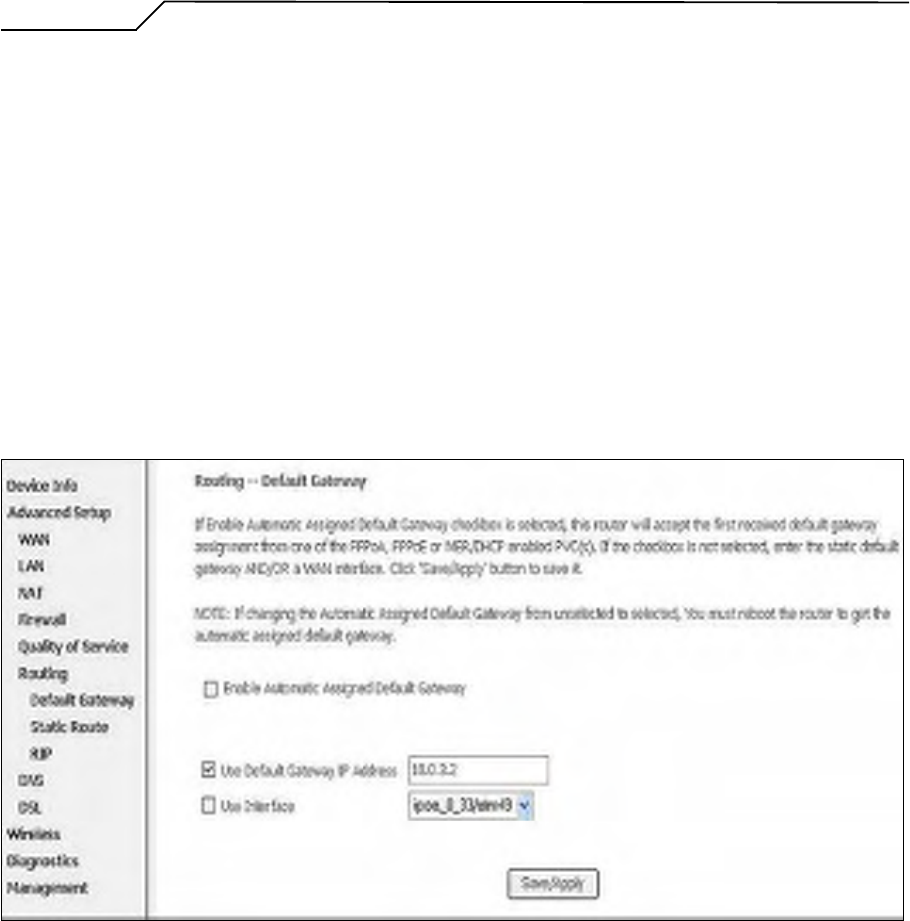
5.6.1 Routing – Default Gateway
If “Enable Automatic Assigned Default Gateway” checkbox is selected, AG10W
will accept the first received default gateway assignment from one of the PPPoA,
PPPoE or MER/DHCP enabled PVC(s). If the checkbox is not selected, enter the
static default gateway AND/OR a WAN interface. Click “Apply” button to save it.
NOTE: If changing the “Enable Automatic Assigned Default Gateway” from
unselected to selected, You must reboot AG10W to activate the automatic assigned
default gateway.
Figure 41. Advanced Setup – Routing – Default Gateway
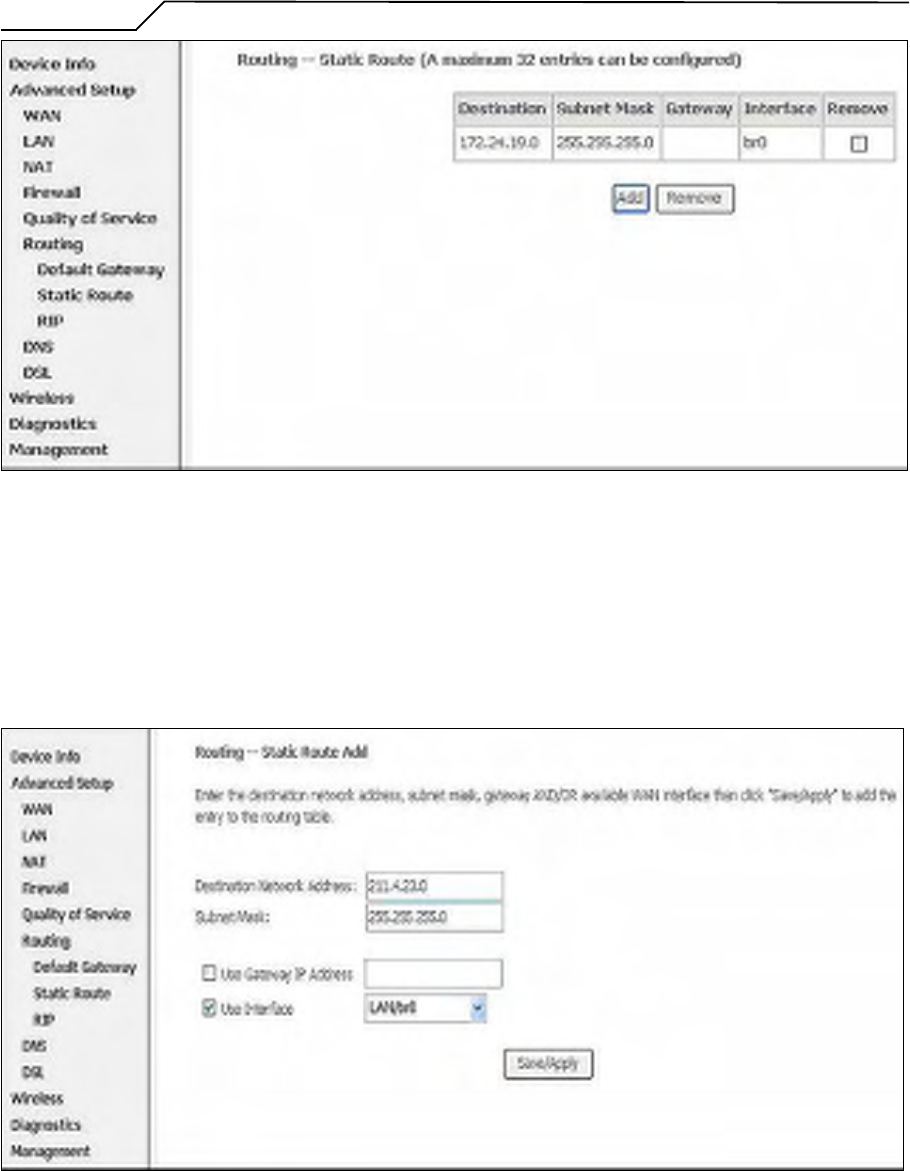
5.6.2 Routing – Static Route
Click on “Add” to create a new Static Route. Up to 32 entries can be configured.
Manual Ver1.0
- 35 -
Figure 42. Advanced Setup – Routing – Static Route
Enter the destination network address, subnet mask, gateway AND/OR
available WAN interface, then click “Apply” to add the entry to the routing
table.
Figure 43. Advanced Setup – Routing – Add new Static Route
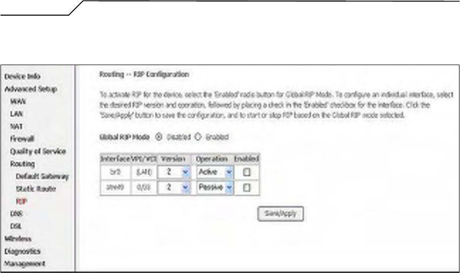
5.6.3 Routing – RIP
Manual Ver1.0
- 36 -
The Routing Information Protocol (RIP) is designed for exchanging routing
information within a small to medium-size Internetwork.
Figure 44. Advanced Setup – Routing – RIP
To configure an individual interface, select the desired RIP version and
operation:
RIP Version 1: Class-based IP network.
RIP Version 2: Classless IP network.
Operation Active: Broadcast and listen to other RIP enabled devices.
Operation Passive: Listen only.
Placing a check in the “Enabled” checkbox for the interface to complete the
configuration. Click the “Apply” button to save the configuration. To start/stop
RIP for AG10W, select the “Enabled/Disabled” radio button for Global RIP
Mode.
5.7 DNS
5.7.1 DNS Server
Manual Ver1.0
- 37 -
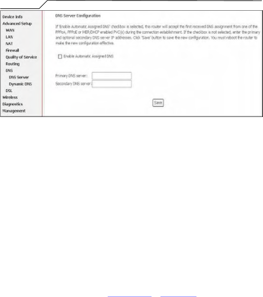
Figure 45. Advanced Setup – DNS Server
If “Enable Automatic Assigned DNS” checkbox is selected, AG10W will accept
the first received DNS assignment from one of the PPPoA, PPPoE or MER/DHCP
enabled PVC(s) during the connection establishment. If the checkbox is not
selected, enter the primary and optional secondary DNS server IP addresses. Click
“Apply” button to save it.
NOTE: If changing from unselected “Enable Automatic Assigned DNS” to
selected, you must reboot AG10W to get the automatic assigned DNS addresses.
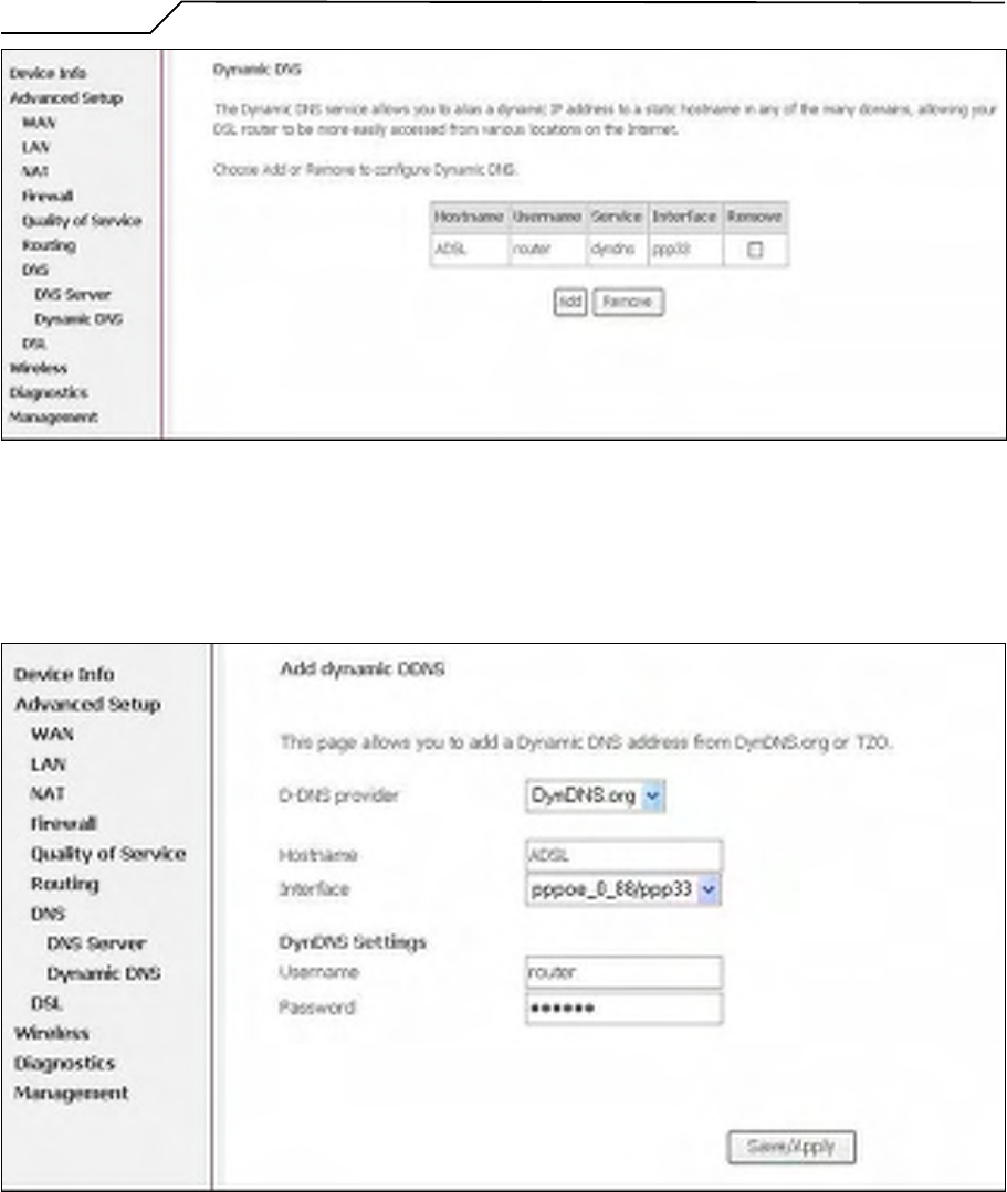
5.7.2 Dynamic DNS
The Dynamic DNS service allows you to alias a dynamic IP address to a static
hostname in any of the domains. This function allows your AG10W to be more
easily accessible from various locations of the Internet.
Choose “Add” to configure Dynamic DNS.
Before you proceed, please visit one of these two website to apply your own
Dynamic DNS service: www.dnadns.org or www.tzo.com.
To remove, check the item and click “Remove”
Manual Ver1.0
- 38 -
Figure 46. Advanced Setup – DNS – Dynamic DNS
Select your Dynamic DNS service provider from ‘D-DNS provider’, and enter
your registration information. Click “Save/Apply” to save the configuration.
Figure 47. Advanced Setup – DNS – Add Dynamic DNS
Manual Ver1.0
- 39 -
6. Wireless Setup
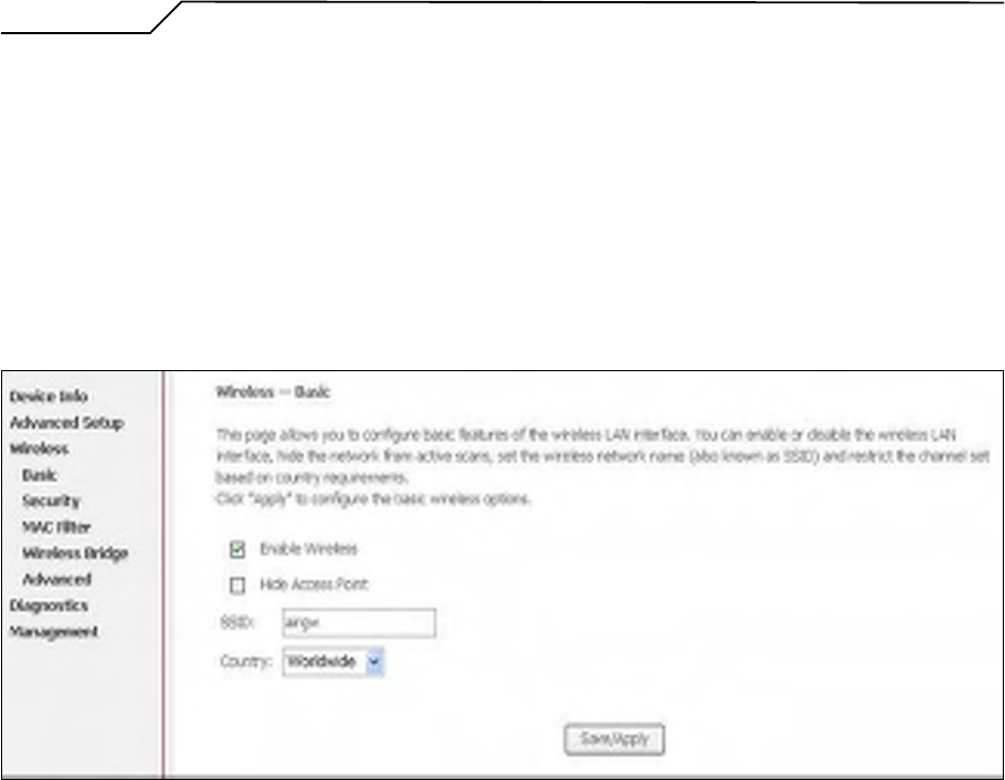
6.1 Basic
This page allows you to configure basic features of the wireless LAN interface. You
can enable or disable the wireless LAN interface, hide the network from active scans
(no broadcasting of your network name), set the wireless network name (also known
as SSID, default: airgw), and restrict the channels based on nation’s requirements.
Click “Save/Apply” to save the configurations.
Figure 48. Wireless Setup – Basic
6.2 Security
Four types of wireless security are provided: Shared (WEP), 802.1x, WPA/WPA2, and
WPA/WPA2-PSK.
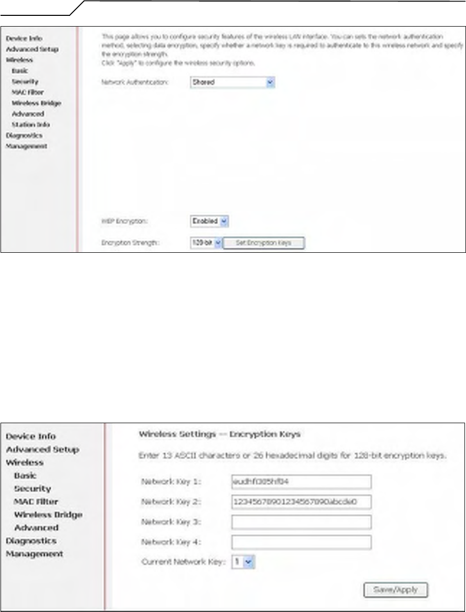
6.2.1 WEP
WEP (Wired Equivalent Privacy) provides security by encrypting data over radio
waves when data is transmitted from one end point to another. WEP is the weakest
security method but the easiest one to configure. To enable WEP, select the
following items step by step:
Network Authentication: Shared
Data Encryption: Enabled
Encryption Strength: 128-bit (recommended for better security) or 64-bit
Click “Set Encryption Key” to enter your WEP keys.
Note to US model owner: To comply with US FCC
regulation, the country selection function has been
completely removed from all US models. The above
function is for non-US models only.
Manual Ver1.0
- 40 -
Figure 49. Wireless Setup – Security – WEP
Four keys for both encryption strengths can be stored here. Enter 13 ASCII
characters or 26 hexadecimal digits for 128-bit encryption keys. Enter 5 ASCII
characters or 10 hexadecimal digits for 64-bit encryption keys. Select which key
(1 ~ 4) to use from “Current Network Key”. Click “Save/Apply” to save the
configuration.
Figure 50. Wireless Setup – Security – WEP
Manual Ver1.0
- 41 -
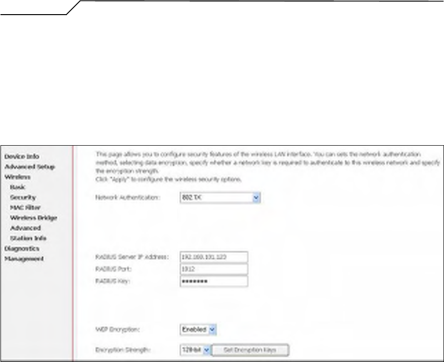
6.2.2 802.1X
802.1X addresses the WEP weakness by adding user authentication, via RADIUS
server. So you need to have your RADIUS server up and running before using
802.1X. To enable 802.1X, select “802.1X” in “Network Authentication”. Enter
your RADIUS server IP address, port number (default: 1812), and key. Follow
section 6.2.1 to configure your WEP key and select “Save/Apply” to save your
configuration.
Figure 51. Wireless Setup – Security – 802.1X
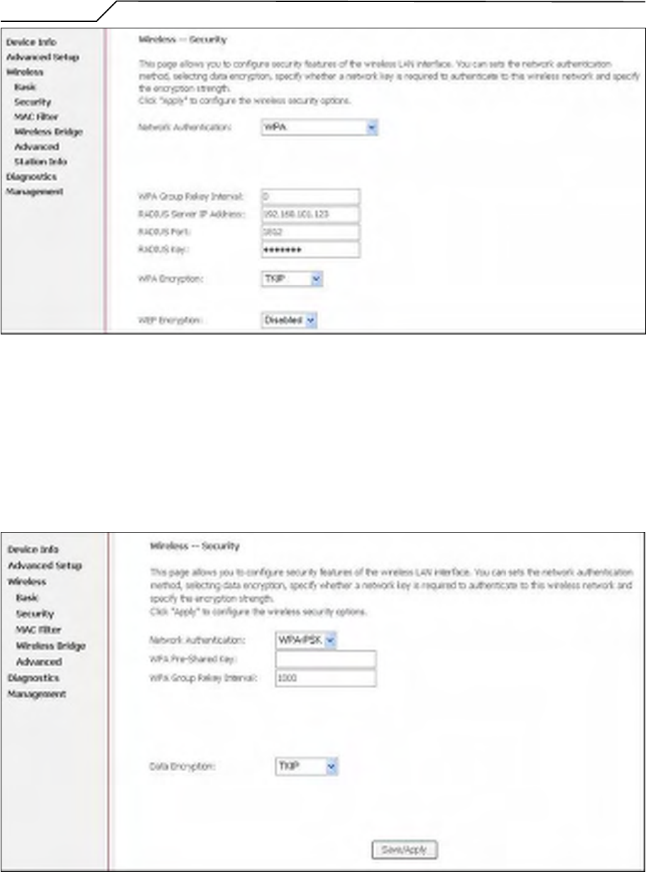
6.2.3 WPA/WPA2
WPA (Wi-Fi Protected Access) is the strongest wireless security provided by
AG10W. Like 802.1X, WPA must co-work with RADIUS server as well. To
enable WPA, select the following items step by step:
Network Authentication: WPA/WPA2
WPA Group Rekey Interval: in seconds. Default: 0 (no re-keying).
RADIUS Server IP Address/Port/Key: must match your RADIUS server.
WPA Encryption: TKIP ( select AES or TKIP+AES for WPA2).
Check your supplicant capability before you decide which one to use.
Manual Ver1.0
- 42 -
Figure 52. Wireless Setup – Security – WPA
6.2.4 WPA/WPA2-PSK
WPA-PSK lets you take advantage of WPA without the hassle of setting up your
own RADIUS server. To enable WPA-PSK, select “WPA-PSK” in “Network
Authentication”. Enter 8 to 63 ASCII codes or 64 hexadecimal (0~9, A~F) digits
in “WPA Pre-Shared Key”. Click “Save/Apply” to save the configuration.
Figure 53. Wireless Setup – Security – WPA-PSK
Manual Ver1.0
- 43 -
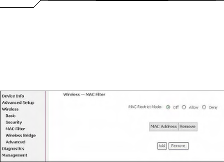
6.3 MAC Filter
Wireless MAC filter allows you to implement access control based on device’s MAC
address.
When you select “Allow” in “MAC Restrict Mode”, only data from devices with
matching MAC addresses in filter table can access AG10W. If you select “Deny” in
“MAC Restrict Mode”, every device can access AG10W except those which have
matching MAC addresses in the filter table. To add filter entry, click on “Add” and
enter the MAC address of AG10W. Click “Save/Apply” to save the configuration. To
“delete” the entry, select the entry and click “Remove”.
Figure 54. Wireless Setup – MAC Filter
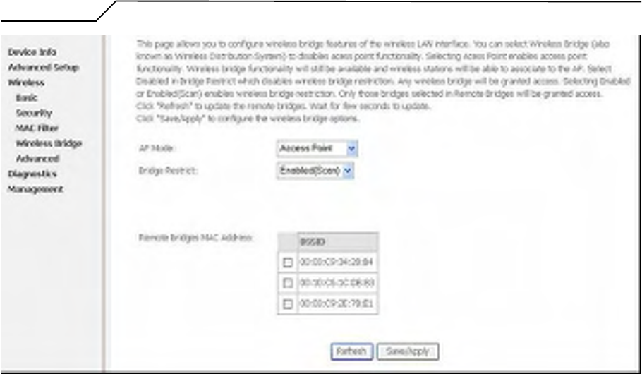
6.4 Wireless Bridge
Wireless Bridge (also known as Wireless Distribution System) can bridge data
between two APs, which is particularly useful while wired cabling is not available.
Note: only APs in same channel can be bridged.
AP Mode: Wireless Bridge- listens and answers other APs only
Access Point- Wireless Bridge also with AP functionality
Bridge Restrict: Disabled- any AP will be granted access
Enabled- only selected APs (Max. 4) with specified MAC address
will be granted access
Enabled (Scan)- as above, but AG10W will scan available AP for
you to select.
Refresh: re-scan the available AP
Save/Apply: save the configuration
Manual Ver1.0
- 44 -
Figure 55. Wireless Setup – Wireless Bridge
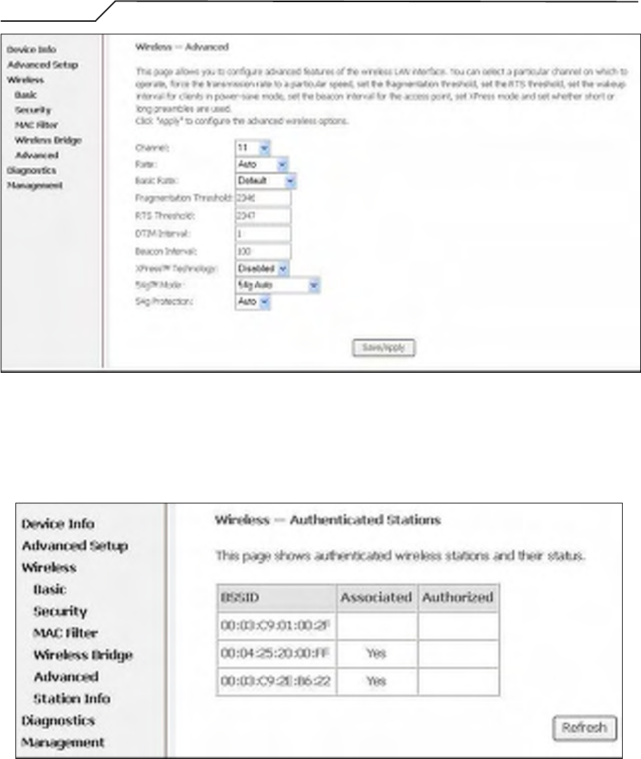
6.5 Advanced
In most cases, AG10W work well with wireless default settings. Modification is not
recommended unless you are very familiar with these parameters.
Channel: Select the appropriate channel from the provided list to correspond with
your network settings. All devices in your wireless network must use the
same channel in order to function correctly. Default: 7.
Rate: The range is from 1 to 54Mbps. The data transmission rate should be set
according to the speed of your wireless network. You can set one transmission
speed, or keep the default setting “Auto” to have the router automatically
detect the fastest possible data rate.
Basic Rate Set: Select the basic rate that wireless clients must support.
Fragmentation: This value should remain at its default setting of 2346. The range is
256-2346 bytes. This value specifies the maximum packet size
before data is fragmented into multiple packets. If you experience a
high packet error rate, you may slightly lower the Fragmentation
value. Setting the Fragmentation too low may result in poor network
performance. Only slight adjustment of this value is recommended.
RTS Threshold: This value should remain at its default setting of 2347. The range is
0-2347 bytes. Should you encounter inconsistent data flow, only

Manual Ver1.0
- 45 -
slight adjustment of this value is recommended. If a network packet
is smaller than the preset RTS threshold size, the RTS/CTS
mechanism will not be enabled. AG10W sends Request to Send
(RTS) frames to a particular receiving station and negotiates the
transmission of a data frame. After receiving an RTS, the wireless
station responds with a Clear to Send (CTS) frame to acknowledge
the right to begin transmission.
DTIM Interval: This value, between 1 and 255 milliseconds, indicates the interval of
the Delivery Traffic Indication Message (DTIM). A DTIM interval is
a countdown field which is used to inform clients about the next
window for listening to broadcast and multicast messages. When
AG10W has buffered broadcast or multicast for associated clients, it
sends the next DTIM with a DTIM Interval value. Its clients hear the
beacons and awaken to receive the broadcast and multicast message.
Default: 3.
Beacon Interval: Enter a value between 1 and 65535 milliseconds. The Beacon
Interval indicates the frequency interval of the beacon. A beacon is
a packet broadcast by AG10W to synchronize the wireless
network. Default: 100.
54g Mode: There are 3 selections. Select 54g Auto for the widest compatibility. Select
54g Performance for the fastest performance. Select 54g LRS if you are
experiencing difficulty with legacy 802.11b equipment.
54g protection: In Auto mode, AG10W will use RTS/CTS to improve 802.11g
performance in mixed 802.11g/802.11b network. Turn off protection
to maximize 802.11g throughput under most conditions.
Manual Ver1.0
- 46 -
Figure 56. Wireless Setup – Advanced
6.6 Station Info
This page shows authenticated wireless stations and their status.
Figure 57. Wireless Setup – Station Info
Manual Ver1.0
- 47 -
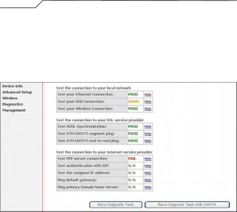
7. Diagnostics
This page allows users to test the Ethernet port connection, DSL port connection, and
connection to the Internet Service Provider. If a test displays a fail status, click “Return
Diagnostic Tests” at the bottom of the page to make sure the fail status is consistent. If
the test continues to show fail, click “Help” to go to the troubleshooting procedures.
Figure 58. Diagnostics
Manual Ver1.0
- 48 -
8. Management
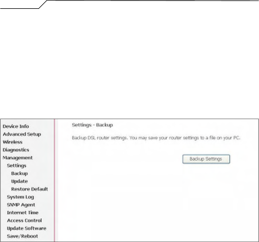
8.1 Settings
System Administrator can do the AG10W settings backup, update, and restore default
here. The settings can be saved from AG10W to PC. The saved setting file can also be
loaded from PC to AG10W. These 2 functions can help the system administrator to
manage large amount of AG10W efficiently. Restore Default would set the AG10W
with the factory default configuration.
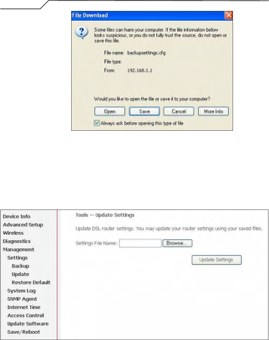
To backup the current configurations, click on “Backup Settings”, and a File
Download window will pop up.
Figure 59. Management – Settings – Backup Settings
Click on “Save” and select the destination of the backup file (backupsettings.cfg) in
your local PC. Click on “Save” again to save your backup file.
Manual Ver1.0
- 49 -
Figure 60. Management – Settings – File Download
To update the configuration, click on “Browse” and a Choose-File-window will pop
up. Locate the saved file and click on “Update Settings”. AG10W will modify its
settings based on the update file.
Figure 61. Management – Settings – Update
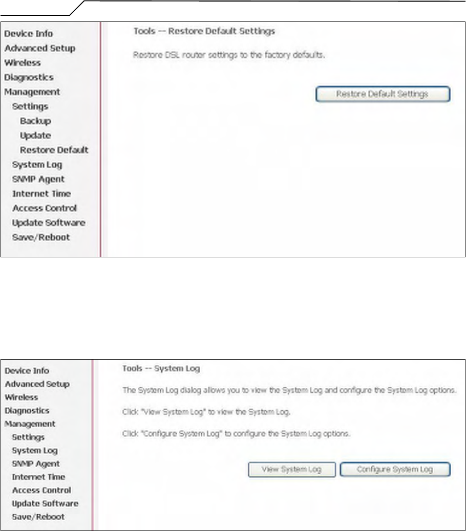
To restore the router to its factory default settings, click on “Restore Default Settings”.
Manual Ver1.0
- 50 -
Figure 62. Management – Settings – Restore Default
8.2 System Log
This allows System Administrator to view the System Log and configure the System
Log options.
Figure 63. Management – System Log
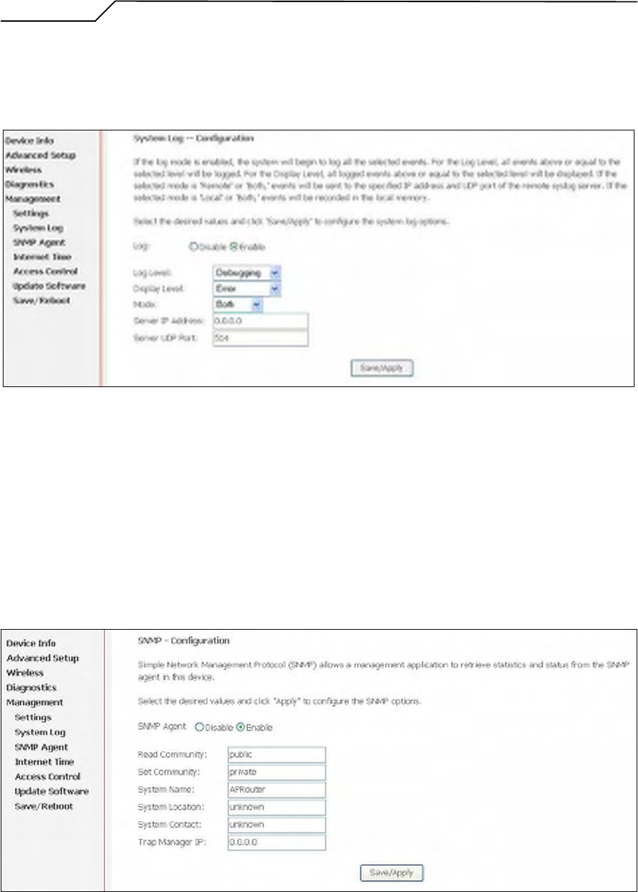
Click on “Configure System Log” to configure the log options. There are 8 events of
“Log Level” and “Display Level”: Emergency, Alert, Critical, Error, Warning,
Notice, Informational, and Debugging. If the log mode is enabled, the system will
begin to log all the selected events. For the Log Level, all events above or equal to the
selected level will be logged. For the Display Level, all logged events above or equal
to the selected level will be displayed.
Manual Ver1.0
- 51 -
If the selected mode is “Remote” or “Both”, events will be sent to the specified IP
address and UDP port of the remote syslog server. If the selected mode is “Local” or
“Both”, events will be recorded in the local memory. Click on “Save/Apply” to save
the configuration.
Figure 64. Management – System Log Configuration
Click on “View System Log” to see the router log based on your configuration.
8.3 SNMP Agent
System Administrator could enable or disable the embedded SNMP Agent here.
SNMP Agent would allow a management application to retrieve AG10W statistics and
status.
Figure 65. Management – SNMP Agent
Manual Ver1.0
- 52 -
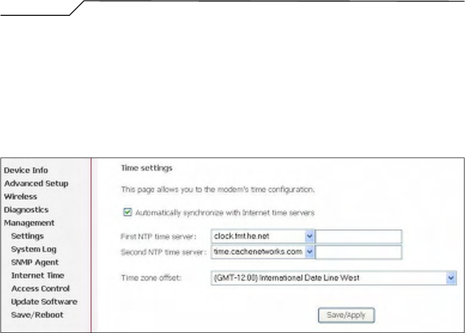
8.4 Internet Time
AG10W can synchronize its internal time with Internet time server when available. To
enable this function, check “Automatically synchronize with Internet time servers”.
Select First and Second NTP time server from the pull down menu. Or select “Other”
and define your preferred NTP server. Choose the time zone from “Time zone offset”.
Click on “Save/Apply” to save the configuration.
Figure 66. Management – Internet Time
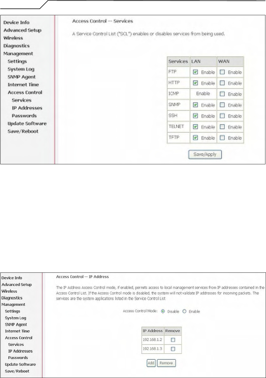
8.5 Access Control
AG10W browser management tool is protected by three categories: Services, IP
addresses, and Passwords. All three must be matched, if configured, to gain access to
the management tool.
All services are enabled from LAN side and disabled from WAN side by default.
Manual Ver1.0
- 53 -
Figure 67. Management – Access Control - Service
The IP Address Access Control mode, if enabled, permits access to local management
services from IP addresses contained in the Access Control List. If the Access Control
mode is disabled, the system will not validate IP addresses for incoming packets. The
services are the system applications listed in the Service Control List.
Click “Add” to add an IP address to the Access Control List. To remove, mark the
Remove option of the specified IP address, then click “Remove” to remove the IP
address from the Access Control List. Up to 16 hosts can be configured here.
Figure 68. Management – Access Control – IP Addresses
Manual Ver1.0
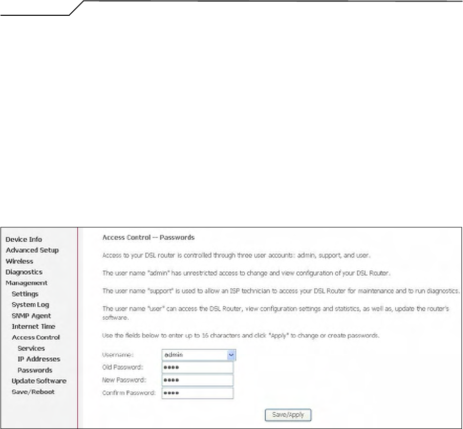
- 54 -
Access to your router is controlled through three user accounts: admin, support, and
user.
admin: has unrestricted access to change and view AG10W configuration.
support: is used to allow an ISP technician to access AG10W for maintenance and to
run diagnostics.
user: can access AG10W to view configuration settings and statistics, as well as,
update AG10W software.
Use the fields below to enter up to 16 characters and click “Save/Apply” to change or
create passwords.
Figure 69. Management – Access Control – Passwords
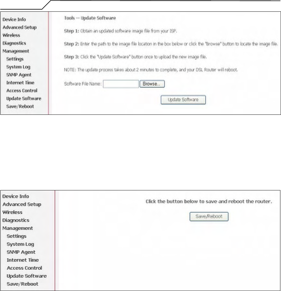
8.6 Update Software
The new software could be updated from the Local PC connected to AG10W via
Ethernet cable. Click on “Browse” to locate the new software image file in the PC.
And then Click on “Update Software” to proceed the software update.
Note: The update process takes about 2 minutes to complete, and your AG10W will
reboot automatically.
Manual Ver1.0
- 55 -
Figure 70. Management – Update Software
8.7 Save/Reboot
Click “Reboot Router” to reboot AG10W. AG10W would automatically save the
configuration before reboot, so that modified settings would take effect after reboot.
Figure 71. Management – Save and Reboot
Manual Ver1.0
- 56 -
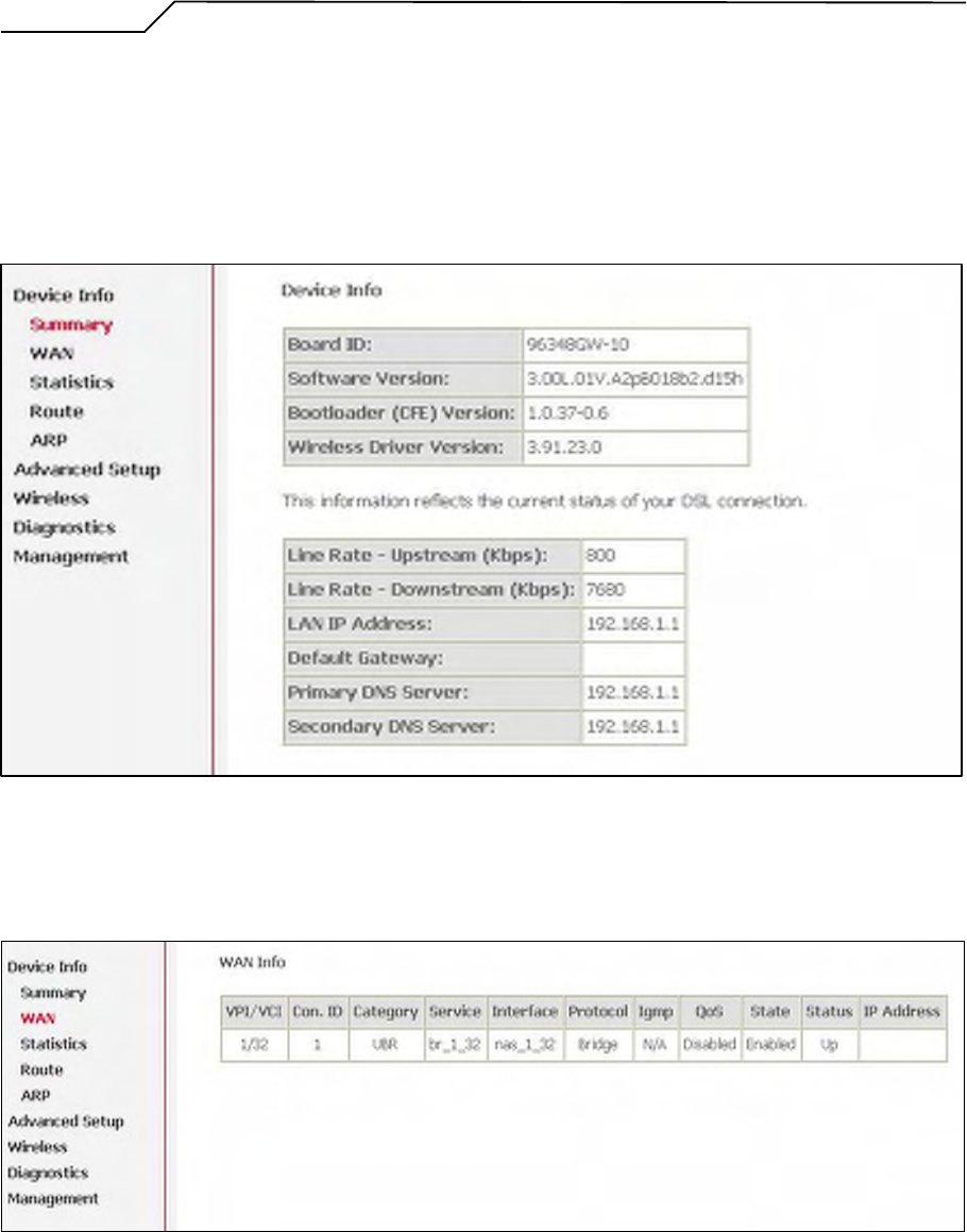
9. Device Info
9.1 Summary
This page displays AG10W’s hardware/software information and DSL connection
status.
Figure 72. Device Info – Summary
9.2 WAN
This page displays AG10W’s WAN interface information and connection status.
Figure 73. Device Info – WAN
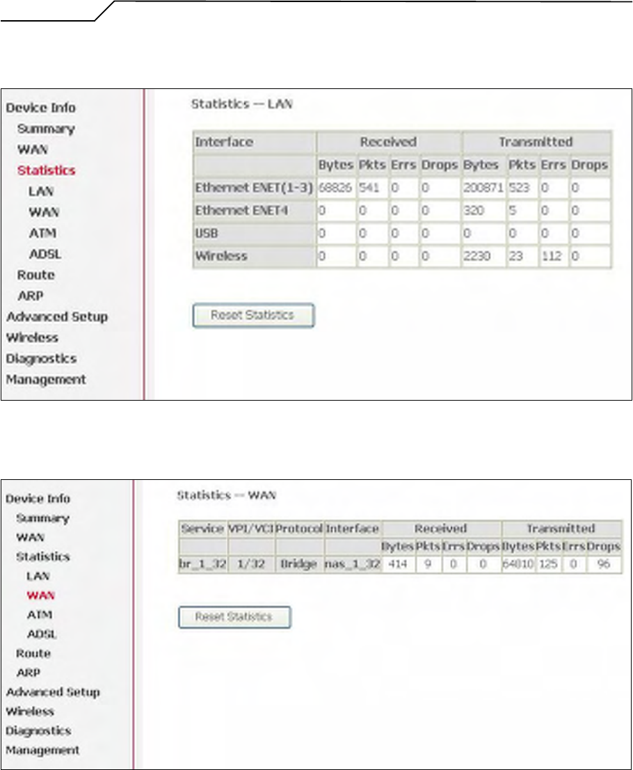
9.3 Statistics
9.3.1 LAN/WAN
Manual Ver1.0
- 57 -
This page displays packets transmitted and received status of AG10W’s LAN/WAN
interfaces.
Figure 74. Device Info – Statistics – LAN
Figure 75. Device Info – Statistics – WAN
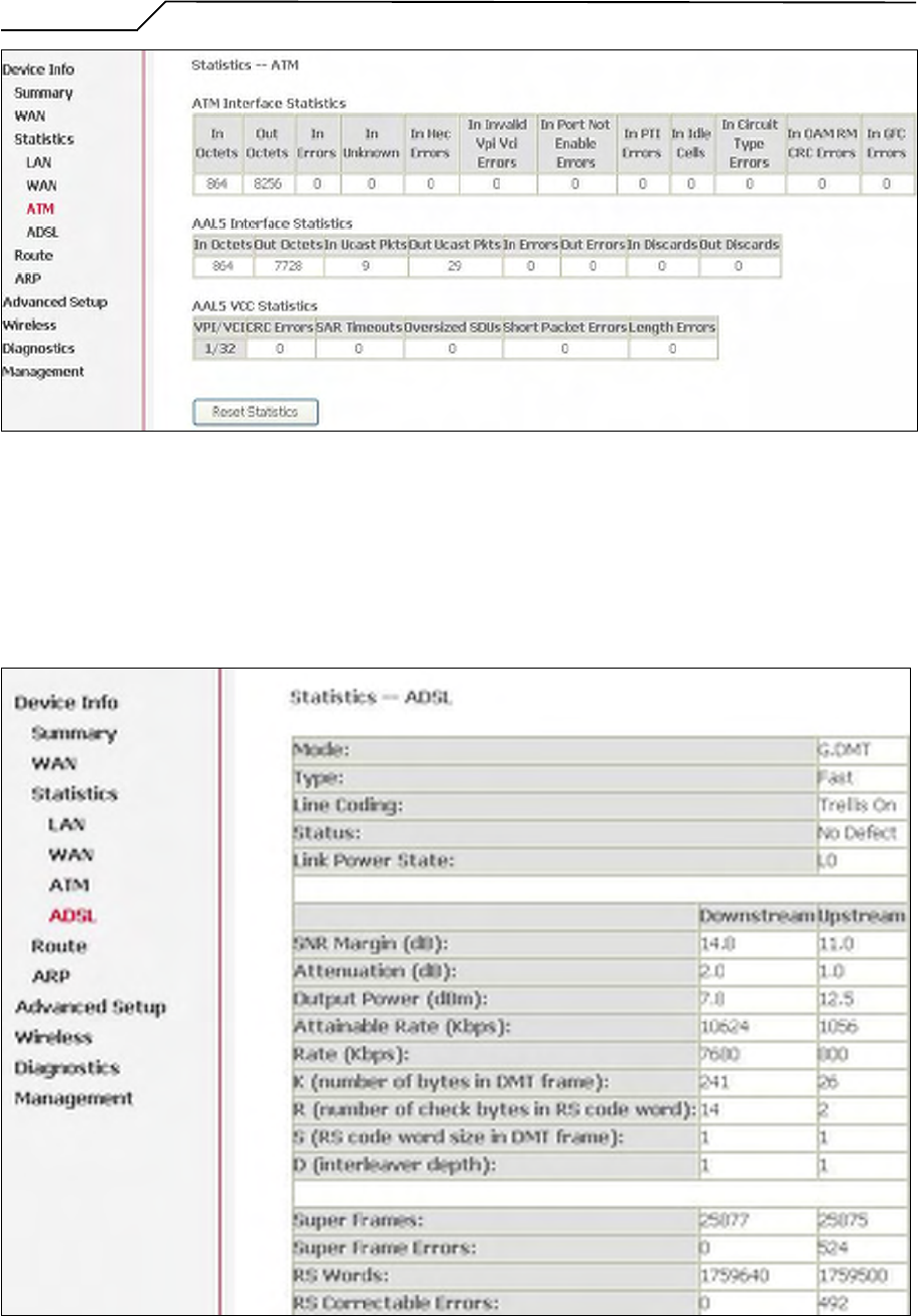
9.3.2 ATM
This page displays the statistics of AG10W’s ATM interface (including AAL5).
Manual Ver1.0
- 58 -
Figure 76. Device Info – Statistics – ATM
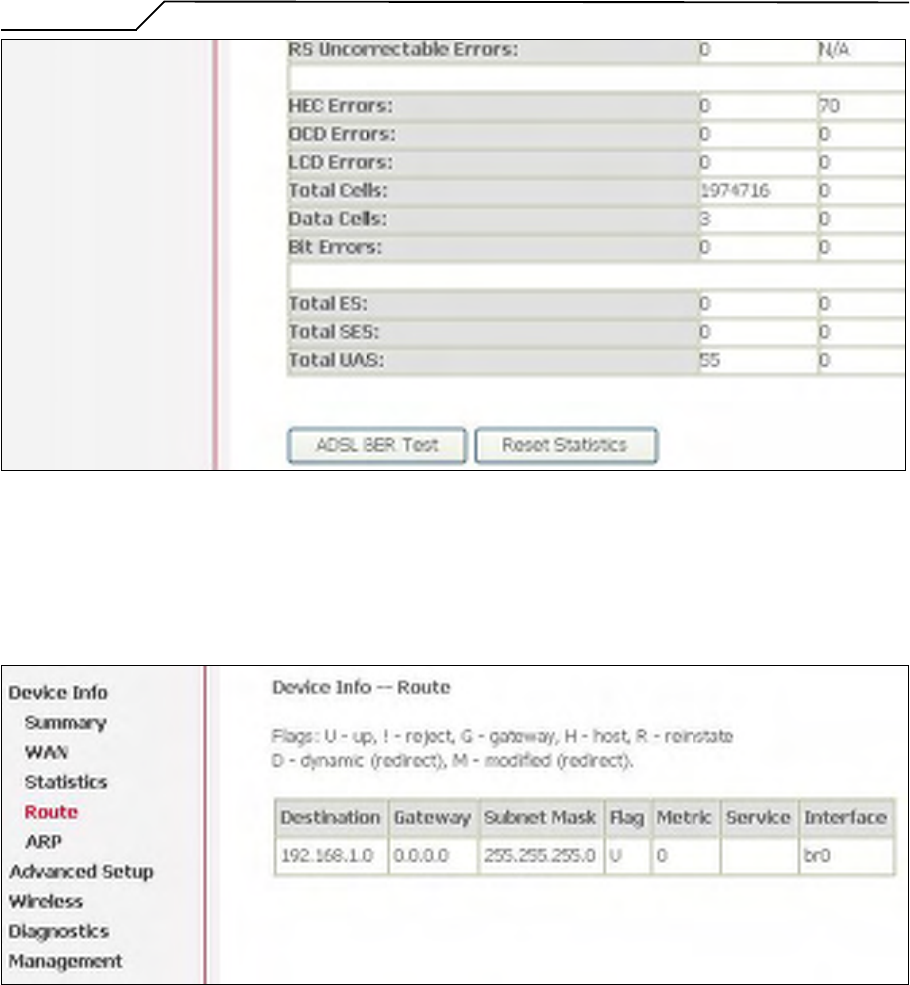
9.3.3 ADSL
This page displays AG10W’s ADSL connection information and status, such as rate,
SNR, ES (Error Second)…etc.
Manual Ver1.0
- 59 -
Figure 77. Device Info – Statistics – ADSL
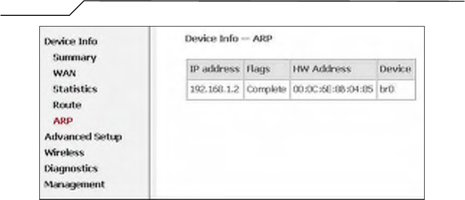
9.4 Route
This page displays AG10W’s routing table.
Figure 78. Device Info – Route
9.5 ARP
This page displays AG10W’s ARP table.
Manual Ver1.0
- 60 -
Figure 79. Device Info – ARP
Part 68 Statement
This equipment complies with Part 68 of the FCC rules and the requirements adopted by the ACTA. On
the base of this equipment is a label that contains, among other information, a product identifier in the
format US: VW7DL01BAG10W. If requested, this number must be provided to the telephone company.
The REN is used to determine the number of devices that may be connected to a telephone line.
Excessive RENs on a telephone line may result in the devices not ringing in response to an incoming call.
In most but not all areas, the sum of RENs should not exceed five (5.0). To be certain of the number of
devices that may be connected to a line, as determined by the total RENs, contact the local telephone
company. For products approved after July 23, 2001, the REN for this product is part of the product
identifier that has the format US: VW7DL01BAG10W. The digits represented by 01B are the REN without a
decimal point (e.g., 03 is a REN of 0.3). For earlier products, the REN is separately shown on the label.
If your equipment causes harm to the telephone network, the telephone company may discontinue your
service temporarily. If possible, they will notify you in advance. But if advance notice is not practical, you
will be notified as soon as possible. You will be informed of your right to file a complaint with the FCC.
Your telephone company may make changes in its facilities, equipment, operations or procedures that
could affect the proper functioning of your equipment. If they do, you will be notified in advance to give
you an opportunity to maintain uninterrupted telephone service.
If you experience trouble with this telephone equipment, please contact the following address and
phone number for information on obtaining service or repairs.
The telephone company may ask that you disconnect this equipment from the network until the problem
has been corrected or until you are sure that the equipment is not malfunctioning.
This equipment may not be used on coin service provided by the telephone company. Connection to
party lines is subject to state tariffs.
Company: ClearAccess Inc
Address: 1206-B NE 146th Street, Vancouver, WA 98685, U.S.A.
Tel no.: (360) 859-1783
A plug and jack used to connect this equipment to the premises wiring and telephone network must
comply with the applicable FCC Part 68 rules and requirements adopted by the ACTA. A compliant
telephone cord and modular plug is provided with this product. It is designed to be connected to a
compatible modular jack that is also compliant. See installation instructions for details.
Federal Communication Commission Interference Statement
This equipment has been tested and found to comply with the limits for a Class B digital
device, pursuant to Part 15 of the FCC Rules. These limits are designed to provide
reasonable protection against harmful interference in a residential installation. This
equipment generates, uses and can radiate radio frequency energy and, if not installed and
used in accordance with the instructions, may cause harmful interference to radio
communications. However, there is no guarantee that interference will not occur in a
particular installation. If this equipment does cause harmful interference to radio or television
reception, which can be determined by turning the equipment off and on, the user is
encouraged to try to correct the interference by one of the following measures:
- Reorient or relocate the receiving antenna.
- Increase the separation between the equipment and receiver.
- Connect the equipment into an outlet on a circuit different from that
to which the receiver is connected.
- Consult the dealer or an experienced radio/TV technician for help.
This device complies with Part 15 of the FCC Rules. Operation is subject to the following two
conditions: (1) This device may not cause harmful interference, and (2) this device must
accept any interference received, including interference that may cause undesired operation.
FCC Caution: Any changes or modifications not expressly approved by the party responsible
for compliance could void the user's authority to operate this equipment.
IEEE 802.11b or 802.11g operation of this product in the U.S.A. is firmware-limited to
channels 1 through 11.
IMPORTANT NOTE:
FCC Radiation Exposure Statement:
This equipment complies with FCC radiation exposure limits set forth for an uncontrolled
environment. This equipment should be installed and operated with minimum distance 20cm
between the radiator & your body.
This transmitter must not be co-located or operating in conjunction with any other antenna or
transmitter.
The availability of some specific channels and/or operational frequency bands are country
dependent and are firmware programmed at the factory to match the intended destination.
The firmware setting is not accessible by the end user.
Part 68 statements:
The REN is used to determine the number of devices that may be connected to a telephone
line. Excessive RENs on a telephone line may result in the devices not ringing in response to
an incoming call. In most but not all areas, the sum of RENs should not exceed five (5.0). To
be certain of the number of devices that may be connected to a line, as determined by the
total RENs, contact the local telephone company. For products approved after July 23, 2001,
the REN for this product is part of the product identifier that has the format US:
VW7DL01BAG10W
. The digits represented by 01B are the REN without a decimal point (e.g., 03 is a REN of 0.3).
For earlier products, the REN is separately shown on the label.
A plug and jack used to connect this equipment to the premises wiring and telephone network
must comply with the applicable FCC Part 68 rules and requirements adopted by the ACTA. A
compliant telephone cord and modular plug is provided with this product. It is designed to be
connected to a compatible modular jack that is also compliant. See installation instructions for
details.
Industry Canada Statement
This device complies with RSS-210 of the Industry Canada Rules. Operation is subject to the
following two conditions:
1) this device may not cause interference and
2) this device must accept any interference, including interference that may cause undesired
operation of the device
This device has been designed to operate with an antenna having a maximum gain of 2dBi.
Antenna having a higher gain is strictly prohibited per regulations of Industry Canada. The
required antenna
impedance is 50 ohms.
To reduce potential radio interference to other users, the antenna type and its gain should be
so chosen that the EIRP is not more than required for successful communication.
IMPORTANT NOTE:
IC Radiation Exposure Statement:
This equipment complies with IC radiation exposure limits set forth for an uncontrolled
environment. This equipment should be installed and operated with minimum distance 20cm
between the radiator & your body.