ADTRAN SR350N WIRELESS ROUTER User Manual E79ZB0Q2 1
SmartRG, Inc. WIRELESS ROUTER E79ZB0Q2 1
ADTRAN >
Users Manual
Wireless Router
Model: SR350N
User Manual
V 1.1

DSL Gateway/Router — User Manual
Page 2 Total 7 Pages
CONTENTS
1.OVERVIEW.............................................................................................................................................................. 3
1.1 ABOUT ADSL ............................................................................................................................................ 3
1.2 ABOUT ADSL2/2+ .................................................................................................................................... 3
1.3 FEATURES ................................................................................................................................................. 3
2 SPECIFICATION .................................................................................................................................................... 4
2.1 INTERFACE INTRODUCTION............................................................................................................... 4
2.1.1 INDICATOR AND INTERFACE ...................................................................................................... 4
2.1.2 SPLITTER SPEC ................................................................................................................................ 4
2.2 HARDWARE CONNECTION .................................................................................................................. 5
2.3 LED STATUS INDICATION ..................................................................................................................... 5
3. CONFIGURATION ................................................................................................................................................ 6
3.1 DEFAULT CONFIGURATION ................................................................................................................. 6
3.2 COMPUTER CONFIGURATION ............................................................................................................ 6
FCC INFORMATION ................................................................................................................................................ 7
THIS DEVICE MUST NOT BE CO-LOCATED OR OPERATING IN CONJUNCTION WITH ANY
OTHER ANTENNA OR TRANSMITTER............................................................................................................. 7
REGULATORY INFORMATION / DISCLAIMERS........................................................................................... 7
SAFETY INFORMATION ........................................................................................................................................ 7

DSL Gateway/Router — User Manual
Page 3 Total 7 Pages
1.OVERVIEW
1.1 ABOUT ADSL
ADSL2+ 4PORT 802.11N Router is a broadband Internet access device, which utilizes the high
frequency segment of the phone line to transmit high-speed data without affecting the voice transmission. The
frequency of the ADSL signal is higher than that of voice, so voice and ADSL signal can coexist in one line by
using a splitter to insulate each from the other. ADSL data transfer adapts the asymmetry model. It supports
upload transmission speed up to 1Mbps and download speed up to 8 Mbps (24Mbps for ADSL2+). ADSL is an
ideal device for broadband access.
1.2 ABOUT ADSL2/2+
Transmission performance of ADSL2 is improved comparing with the first generation of ADSL. These
improvements are mainly concerned with long distance, anti-line-loss, anti-noise, etc. By doubling the
transmission bandwidth, ADSL2+ has implemented a downlink rate as high as 24 Mbps. Therefore, Internet
applications such as synchronous transmission of multi video stream, online games and huge capacity of
downloading files are made possible.
1.3 FEATURES
1、 Support ANSI T1.413 ISSUE 2, ITU G.992.1 (G.DMT), ITU G.992.2 (G.LITE), ITU G992.3, ITU
G992.5
2、 Web-based configuration and monitoring.
3、 Support multiple PVCs.
4、 Routing function,including static routing and RIP
5、 DNS function ,including DNS server , DNS Relay, DDNS
6、 NAPT, DHCP, Firewall, UPNP function.
7、 Quality of Service Control for Traffic Prioritization.
8、 Supports Virtual Private Network (VPN) pass-through.
9、 Support 802.11n, 802.11b, 802.11g.
10、 Support Multiple SSID
11、 Support Wireless MAC Filter, Wireless Bridge ,WPS(Push-Button and PIN).
12、 Diagnostics function.
13、 Support SNMP , TR069 and TR064 to manage the device.
14、 AccessControl function.
15、 Device LOG function
16、 Update software via WEB, CLI, TR069
DSL Gateway/Router — User Manual
Page 4 Total 7 Pages
2 SPECIFICATION
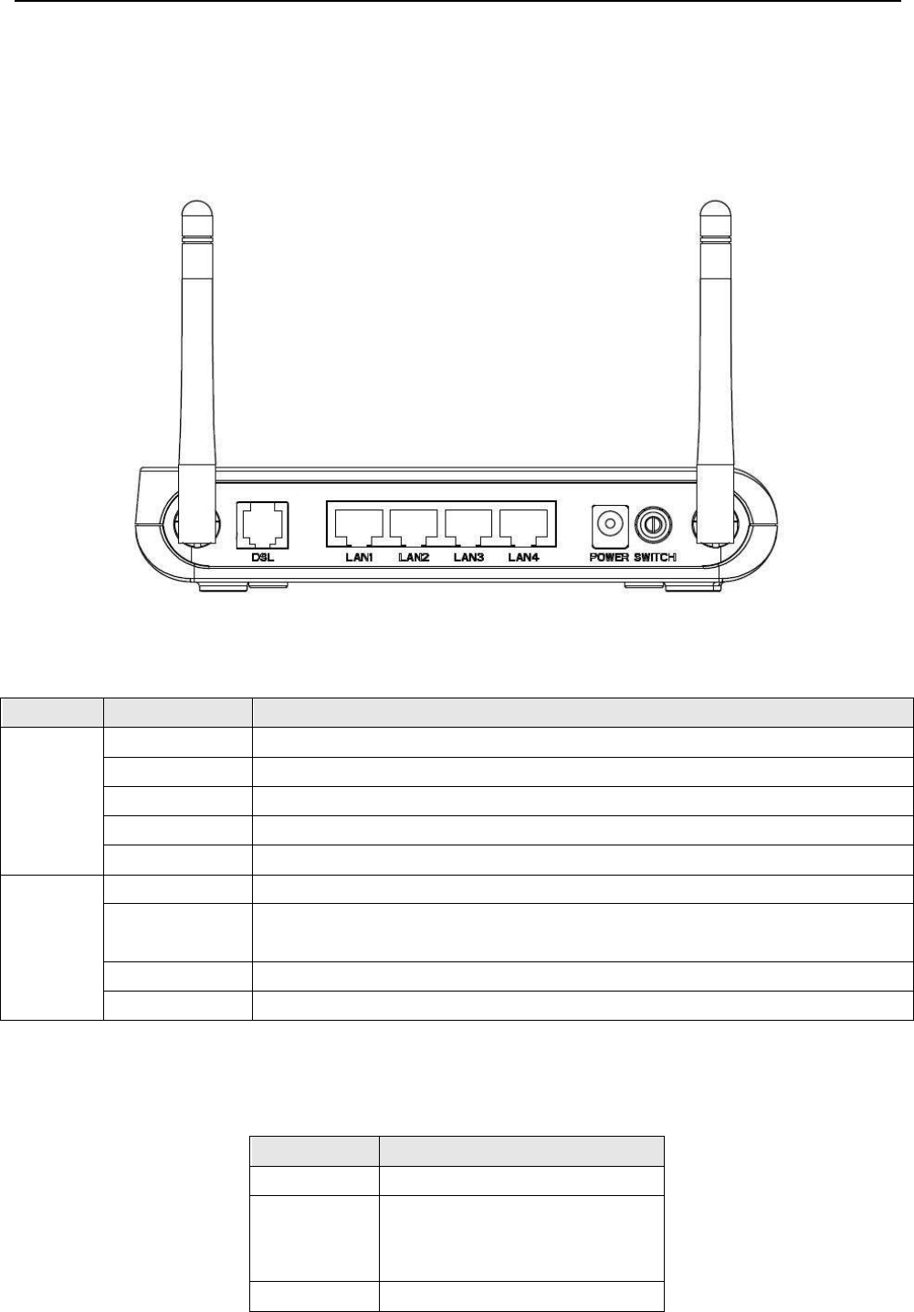
2.1 INTERFACE INTRODUCTION
2.1.1 INDICATOR AND INTERFACE
Table 2.1
ITEM
Name
State introduction
Indicator
POWER
A steady Green light means the power connection works properly
DSL
Green, shows DSL line status.
INTERNET
Green, Flashing means the Modem is transmitting or receiving data
LAN1-LAN4
Green, Flashing means the ethernet is transmitting or receiving data
WLAN
Green, Indicates status of connection to the wireless device
Interface
LINE
Connected with phone line or “ADSL” port of the splitter.
ETHERNET
To be connected to a PC network card by a straight-through network cable, also
can use a crossover cable to connect to Hub, Switch or Router.
POWER
Power interface, Connect with power adapter.
SWITCH
To turn on / off the power.
2.1.2 SPLITTER SPEC
Table 2.2
Interface
Introduction
LINE
Connected with telephone line
ADSL
Connect with the LINE port of the
ADSL Modem using telephone
line provided.
PHONE
Connect with telephone

DSL Gateway/Router — User Manual
Page 5 Total 7 Pages
2.2 HARDWARE CONNECTION
Introduction:
1、 Use a telephone cord to connect the LINE port of the splitter with the RJ-11 port (the phone jack) on
the wall.
2、 Use another telephone cord to connect the ADSL port of the splitter with the LINE port of the ADSL
Modem.
3、 Use another telephone cord to connect the telephone set with the PHONE port of the splitter.
4、 Connect Ethernet port of the ADSL MODEM with 10/100BASE-T port of the computer using the
network cable that comes with the modem.
5、 Plug in the power cord, and turn on the power.
If you do not want Internet services and telephone voice services simultaneously, please just connect the
LINE port of the ADSL Modem with the RJ-11 port (the phone jack) on the wall using a telephone cord. In this
case, the splitter is not necessary.
2.3 LED STATUS INDICATION
Table 2.3
Status
POWER
(red)
DSL (green)
INTERNET
(green)
LAN1-LAN4
WIRELESS(green)
Steady
light
Power on
The modem is in
good connection
/
Wireless is connected
Flashing
/
In handshaking
status
/
/
Fast
flashing
/
/
Transmitting or
receiving data
Transmitting
or receiving
data
Transforming data
Off
Power off
Connection not set
up
Not connected
with PC
properly
Not
connected
with PC
properly
Wireless is disabled

DSL Gateway/Router — User Manual
Page 6 Total 7 Pages
3. CONFIGURATION
3.1 DEFAULT CONFIGURATION
ADSL MODEM has pre-configured with the VCI/VPI which is in common use.
3.2 COMPUTER CONFIGURATION
The default IP address for ADSL MODEM is: 192.168.1.1; The Subnet Mask is:255.255.255.0. Users can
configure ADSL MODEM through an Internet browser. ADSL MODEM can be used as gateway and DNS
server; users need to set the computer’s TCP/IP protocol as follow:
1、 Set the computer IP address at same segment of ADSL MODEM, such as set the IP address of the
network card to one of the “192.168.1.2”~ “192.168.1.254”.
2、 Set the computer’s gateway the same IP address as the ADSL Modem’s.
3、 Set computer’s DNS server the same as ADSL Modem’s IP address or that of an effective DNS server.

DSL Gateway/Router — User Manual
Page 7 Total 7 Pages
FCC INFORMATION
This equipment complies with CFR 47, Part 15.19 of the FCC rules. Operation of the equipment is subject to the following
conditions: (1) this device may not cause harmful interference, and (2) this device must accept any interference received; including
interference that may cause undesired operation.
THIS DEVICE MUST NOT BE CO-LOCATED OR OPERATING IN CONJUNCTION WITH ANY OTHER ANTENNA OR TRANSMITTER
NOTE: THE MANUFACTURER IS NOT RESPONSIBLE FOR ANY RADIO OR TV INTERFERENCE CAUSED BY
UNAUTHORIZED MODIFICATIONS TO THIS EQUIPMENT. SUCH MODIFICATIONS COULD VOID THE USER’S
AUTHORITY TO OPERATE THE EQUIPMENT.
Federal Communications Commission (FCC) Requirements, Part 15
This equipment has been tested and found to comply with the limits for a class B digital device, pursuant to part 15 of the FCC
Rules. These limits are designed to provide reasonable protection against harmful interference in a residential installation.
This equipment generates, uses and can radiate radio frequency energy and, if not installed and used in accordance with the
instructions, may cause harmful interference to radio communications. However, there is no guarantee that interference will not
occur in a particular installation. If this equipment does cause harmful interference to radio or television reception, which can be
determined by turning the equipment off and on, the user is encouraged to try to correct the interference by one or more of the
following measures:
---Reorient or relocate the receiving antenna.
---Increase the separation between the equipment and receiver.
---Connect the equipment into an outlet on a circuit different from that to which the receiver is connected.
---Consult the dealer or an experienced radio/TV technician for help.
REGULATORY INFORMATION / DISCLAIMERS
Installation and use of this Wireless LAN device must be in strict accordance with the instructions included in the user
documentation provided with the product. Any changes or modifications (including the antennas) made to this device that are not
expressly approved by the manufacturer may void the user’s authority to operate the equipment. The manufacturer is not
responsible for any radio or television interference caused by unauthorized modification of this device, or the substitution of the
connecting cables and equipment other than manufacturer specified. It is the responsibility of the user to correct any interference
caused by such unauthorized modification, substitution or attachment. Manufacturer and its authorized resellers or distributors will
assume no liability for any damage or violation of government
CAUTION: To maintain compliance with FCC’s RF exposure guidelines, this equipment should be installed and operated
with minimum distance 20cm between the radiator and your body. Use on the supplied antenna. Unauthorized antenna,
modification, or attachments could damage the transmitter and may violate FCC regulations.
MPE Statement (Safety Information)
Your device contains a low power transmitter. When device is transmitted it sends out Radio Frequency (RF) signal.
SAFETY INFORMATION
In order to maintain compliance with the FCC RF exposure guidelines, this equipment should be installed and operated with
minimum distance 20cm between the radiator and your body. Use only with supplied antenna. Unauthorized antenna, modification,
or attachments could damage the transmitter and may violate FCC regulations.