ADTRAN SR500N 4PORTS VDSL2 11N MODEM WITH GIGA WAN User Manual
SmartRG, Inc. 4PORTS VDSL2 11N MODEM WITH GIGA WAN
ADTRAN >
Users Manual
4PORTS VDSL2 11N MODEM WITH GIGAWAN
SR500N
User Manual

ZXDSL 831AII User Manual
- 2 -
CONTENTS
1. OVERVIEW .................................................................................................................................................................................... 5
1.1 ABOUT VDSL ................................................................................................................................................................. 5
1.2 DEVICE INTRODUCTION ........................................................................................................................................... 5
1.3 LED STATUS INDICATION .......................................................................................................................................... 6
1.4 PROTOCOLS ................................................................................................................................................................. 6
1.5 FEATURES ..................................................................................................................................................................... 6
2. HARDWARE INSTALLATION AND SOFTWARE CONFIGURATION ................................................................................. 7
2.1 SYSTEM REQUIREMENT ........................................................................................................................................... 7
2.2 HARDWARE INSTALLATION ...................................................................................................................................... 7
2.2.1 HARDWARE CONNECTION ................................................................................................................................ 7
2.2.2 INSTALLATION STEPS ......................................................................................................................................... 7
2.3 SOFTWARE CONFIGURATION ................................................................................................................................. 8
2.3.1 PREPARATION BEFORE SOFTWARE INSTALLATION .................................................................................... 8
2.3.2 COMPUTER CONFIGURATION ........................................................................................................................... 8
2.3.3 VDSL MODEM CONFIGURATION ...................................................................................................................... 8
2.3.4 VDSL MODEM WORK MODE CONFIGURATION ............................................................................................ 9
3. PROTOCOL CONFIGURATION ............................................................................................................................................... 10
3.1 CONFIGURATION GUIDE ......................................................................................................................................... 10
3.2 RFC1483 BRIDGE CONFIGURATION .................................................................................................................... 12
3.3 PPPOA AND PPPOE CONFIGURATION ................................................................................................................ 14
4.1 TCP/IP PROTOCOL CONFIGURATION .................................................................................................................. 19
4.2 MODEM CONFIGURATION ...................................................................................................................................... 19
5. OTHER FUNCTIONS AND CONFIGURATION ...................................................................................................................... 21
5.1 STATUS CHECKING................................................................................................................................................... 21
5.2 CONFIGURATION OF MODEM’S IP ADDRESS AND PASSWORD ................................................................... 22
6. RESET TO DEFAULT SETTING .............................................................................................................................................. 23
7. USAGE OF USB INTERFACE ................................................................................................................................................ 24
7.1 DRIVER INSTALLATION ............................................................................................................................................ 24
7.2 UNINSTILL DRIVER ................................................................................................................................................... 26
7.3 CONFIGURATION OF "USB IAD LAN MODEM" ................................................................................................... 27
8. SPECIFICATION ......................................................................................................................................................................... 29
8.1 POWER SUPPLY ........................................................................................................................................................ 29
8.2 STANDARDS ............................................................................................................................................................... 29
8.3 ENVIRONMENT REQUIREMENTS ......................................................................................................................... 29
APPENDIX ....................................................................................................................................................................................... 30
APPENDIX A. TROUBLESHOOTING ............................................................................................................................. 30
APPENDIX B. SPLITTER CONNECTION ...................................................................................................................... 31
APPENDIX C. CONFIGURATION OF TCP/IP PROTOCOL ........................................................................................ 32
APPENDIX D. SHIPPING LIST ........................................................................................................................................ 34
FCC INFORMATION ..................................................................................................................................................................... 35
THIS DEVICE MUST NOT BE CO-LOCATED OR OPERATING IN CONJUNCTION WITH ANY OTHER ANTENNA
OR TRANSMITTER ....................................................................................................................................................................... 35
REGULATORY INFORMATION / DISCLAIMERS ................................................................................................................... 35
SAFETY INFORMATION .............................................................................................................................................................. 35

ZXDSL 831AII User Manual
- 3 -
Caution
This device complies with Part15 of the FCC Rules.Operation is subject to the
following conditions:
(1)this device may not cause harmful interference,and
(2) this device must accept any interference received,including interference that
may cause undesired operation
Related Documents
Definition & Acronyms
VDSL Very-High-Bit-Rate Digital Subscriber Loop
DHCP Dynamic Host Configruration Protocol
FEXT Far-end Cross Talk
HDSL High-rate Digital Subscriber Line
POTS Plain Old Telephone Service
PSTN Public Switched Telephone Network
WINS Windows® Internet Name Server
ADSL Asymmetric Digital Subscriber Line
OAM Operations, Administration And Maintenance
QAM Quadrature Amplitude Modulation
DMT Discrete Multitone
DSL Digital Subscriber Line
FEC Forward Error Correction
ATM Asynchronous Transfer Mode
WAN Wide Area Network
PRD Pseudo-random Downstream
PRU Pseudo-random Upstream
USB Universal Serial Bus
LAN Local Area Network
PVC Permanent Virtual Circuit
SVC Switched Virtual Circuit
PPP Point to Point protocol
DNS Domain Name Server
VPI Virtual Path ID
VCI Virtual Circuit ID
IP Internet Protocol

ZXDSL 831AII User Manual
- 4 -
CO Central Office
EC Echo Canceling
ZXDSL 831AII User Manual
- 5 -
1. OVERVIEW
1.1 ABOUT VDSL
VDSL is a fast version of ADSL.VDSL MODEM is a broadband Internet access device,which utilizes
the high frequency segment of the phone line to transmit high-speed data without interfering with the voice
transmission. The frequency of VDSL signal is higher than that of voice, so voice and VDSL signal can coexist
in one line by using a splitter to insulate each from the other. VDSL data transfer on the asymmetry way. The
upload speed is up to 19.2Mbps and download speed is up to 55Mbps. It is an ideal device for broadband
access.
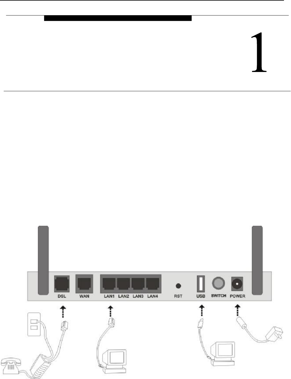
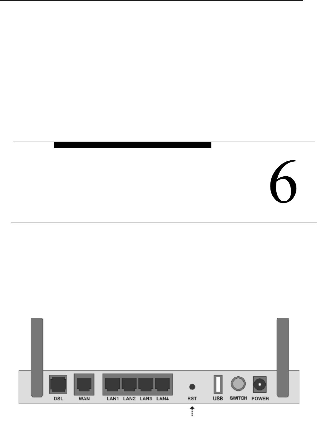
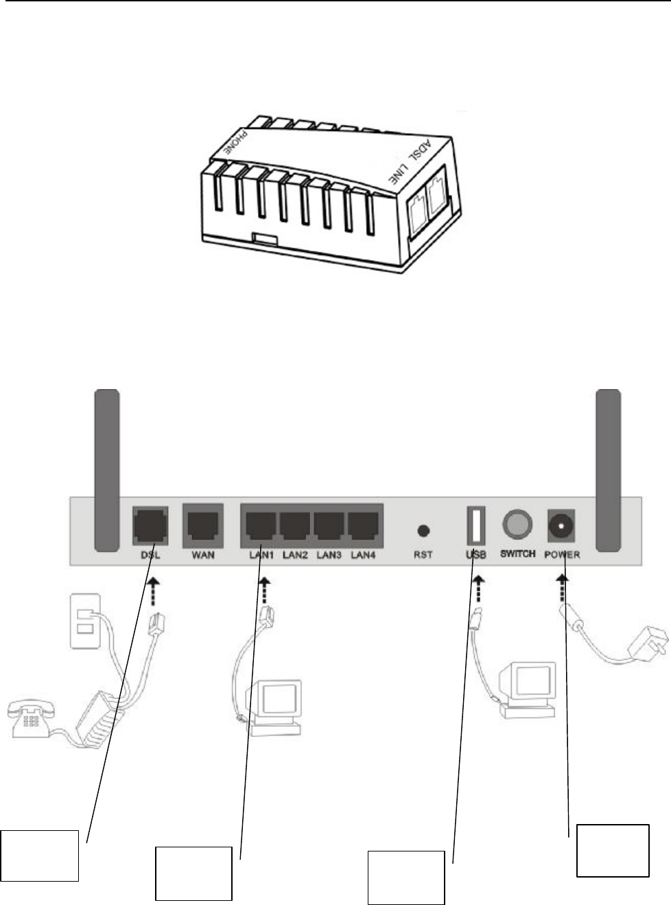
1.2 DEVICE INTRODUCTION
Figure 1.1
Interface introduction:
① Power Interface: 12V DC,1.25A.
OVERVIEW

ZXDSL 831AII User Manual
- 6 -
② Power switch: To turn on or turn off the power.
③ Reset Key: Reset default configuration.
④ Ethernet Interface: To be connected to a PC network card by a network cable, also can use a crossover cable
to connect to Hub, Switch or Router.
⑤ Line Interface: Connected with phone line or “VDSL” port of the splitter.
1.3 LED STATUS INDICATION
Table 1.1
Status POWER
(green)
LINK (green) DATA (green) USB(green)
WiFi (green)
Steady
light
Power on
The modem is
in good
connection
PPP is on USB line is
connected
Wireless is connected
Flashing / No signal / USB port transmit or
receive data
/
Fast
flashing
/ In handshaking
status
Transmitting or
receiving data in PPP
mode
/ /
Off Power off
Power off PPP is Off USB line not
connected properly
Wireless is not
connected
1.4 PROTOCOLS
VDSL Modem supports the following protocols:
1. PPPoA(PPP over ATM ) LLC encapsulation or VCMUX encapsulation (RFC2364)
2. PPPoE (PPP over Ethernet) LLC encapsulation or VCMUX encapsulation (RFC2516)
3. 1483 bridge(1483 Bridged IP over ATM)LLC encapsulation or VCMUX encapsulation (RFC1483)
4. 1483 routing(1483 Routing IP over ATM)LLC encapsulation or VCMUX encapsulation (RFC1483)
5. Classical IP over ATM (RFC1577)
1.5 FEATURES
1. Supports ANSI T1.413 ISSUE 2, ITU G.992.1(G.DMT), ITU G.992.2(G.LITE), ITU G.992.3, ITU G.992.5.
2. Web-based configuration and monitoring.
3. Supports up to 8 PVCs.
4. Routing function.
5. NAPT、DHCP function.
6. Software upgradeable.
7. ATM management function.
ZXDSL 831AII User Manual
- 7 -
2. HARDWARE INSTALLATION AND SOFTWARE
CONFIGURATION
2.1 SYSTEM REQUIREMENT
A computer with a USB interface or a network card with Ethernet interface.
2.2 HARDWARE INSTALLATION
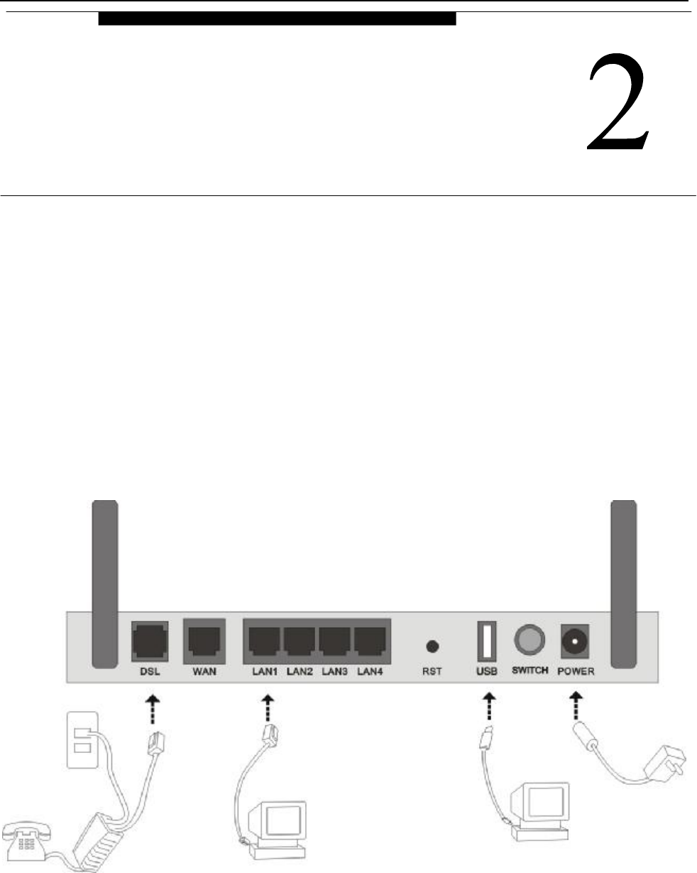
2.2.1 HARDWARE CONNECTION
Figure 2.1
To go online and make phone calls simultaneously, please refer to Appendix B: SPLITTER CONNECTION.
2.2.2 INSTALLATION STEPS
1. Connect line port of the VDSL MODEM to telephone jack with the telephone cord that comes with the
HARDWARE INSTALLATION AND
SOFTWARE CONFIGURATION

ZXDSL 831AII User Manual
- 8 -
modem.
2. Connect Ethernet port of the VDSL MODEM to Ethernet port of the computer using the network cable that
comes with the modem.
3. Connect USB port of the VDSL MODEM to USB port of the computer using the USB cable that comes
with the modem.
4. Plug in the power cord , and turn on the power.
2.3 SOFTWARE CONFIGURATION
2.3.1 PREPARATION BEFORE SOFTWARE INSTALLATION
Before the installation, please confirm information below or consult with the VDSL service provider. Table
2.1 shows all the information needed to configure for different protocols.
Table 2.1
Protocol Virtual Dial Mode Private Line Mode
PPPOE PPPOA 1483 Bridged
Necessary
Information
VPI VPI VPI
VCI VCI VCI
User name User name
Password Password
2.3.2 COMPUTER CONFIGURATION
The default factory-set IP Address for the VDSL MODEM is: 192.168.1.1. The Subnet Mask is:
255.255.255.0. Users can configure VDSL MODEM through an Internet browser. VDSL MODEM can be used
as a gateway and DNS server and users need to set the computer’s TCP/IP protocol as follow:
1. Set the computer at same Internet segment with VDSL MODEM so as to enter VDSL MODEM
configuration page through a browser.
2. Set the computer’s gateway’s IP address the same as the VDSL Modem’s.
3. Set the computer’s DNS server’s IP address the same as the VDSL Modem’s or that of an effective DNS
server.
If the user has any question regarding the computer’s TCP/IP protocol, please refer to APPENDIX C:
TCP/IP PROTOCOL CONFIGURATION.
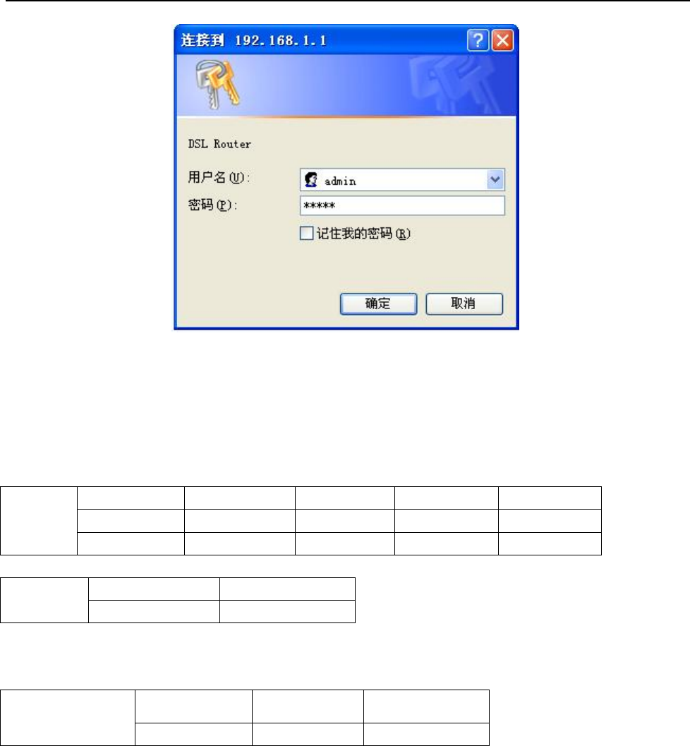
2.3.3 VDSL MODEM CONFIGURATION
Open the browser; input http://192.168.1.1 in the address column. Press “Enter” key then the entry dialog
box will pop up as Figure 2.2, Input username: admin, and password: admin (Note that this is capital
sensitive), then press “Enter”. The VDSL MODEM configuration page will be shown.
ZXDSL 831AII User Manual
- 9 -
Figure 2.2
2.3.4 VDSL MODEM WORK MODE CONFIGURATION
1. For different protocols, the users need to set VDSL Modem accordingly as listed below:
Table 2.2
PPPoE
PPPoA
ATM VC Protocol Use DNS User Name Password
√ PPPoE Enable √ √
√ PPPoA Enable √ √
1483 Bridged
Lower interface Default route
√ Disable
Note: √ means configure according to VDSL service provider’s instructed value.
PPPoE can also be realized via third party dialup software.
User Manual
Reference Chapter
PPPoE PPPoA 1483 Bridged
3.3 3.3 3.2
2. After getting through every page for parameters set-up, click “Apply” to save the value in VDSL MODEM
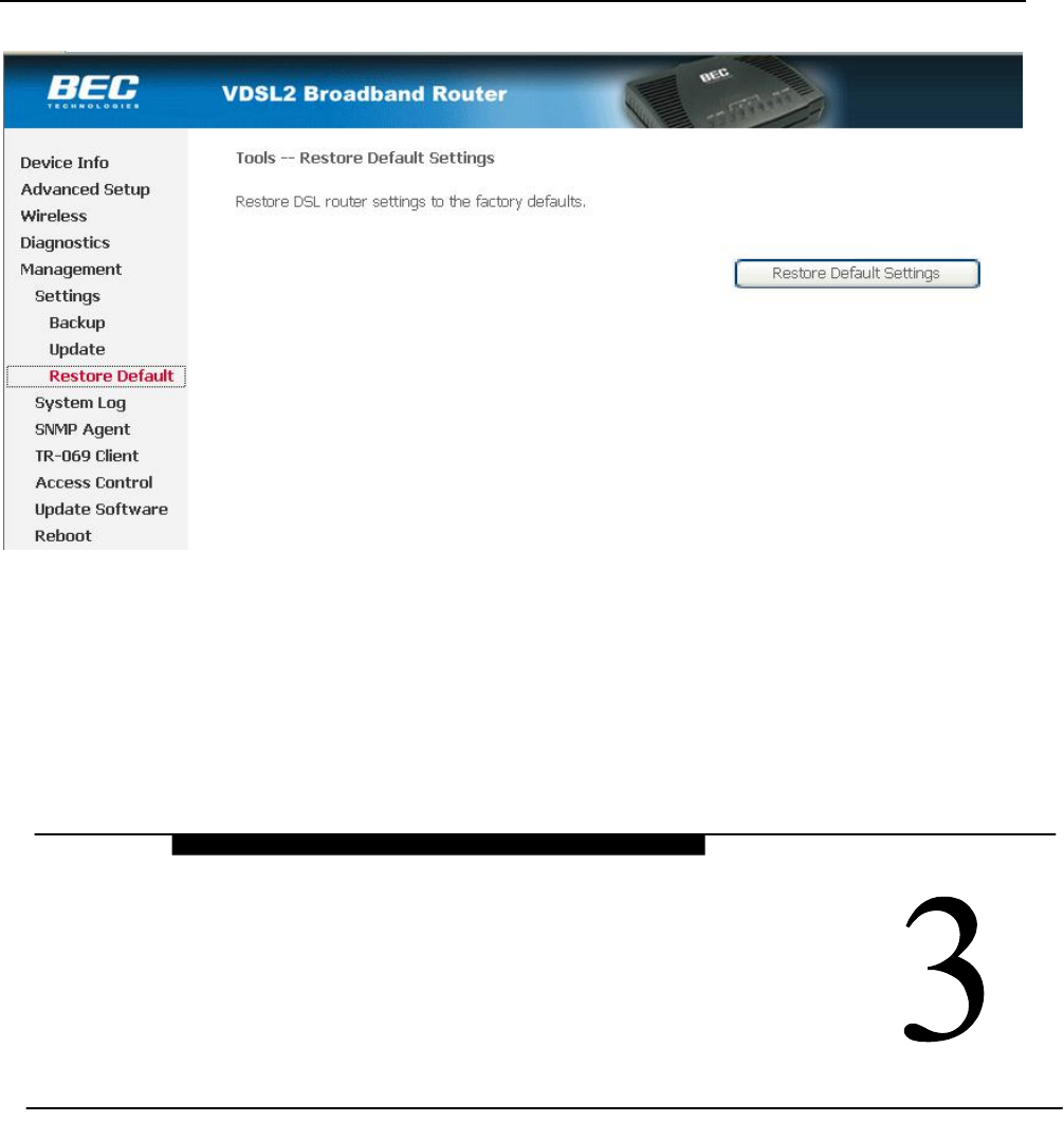
3. Click the “Restore Default Settings” on “Management” Tab to enter the saving configuration page as
Figure 2.3. After the Modem reboot,The VDSL MODEM will work on the new parameters.
ZXDSL 831AII User Manual
- 10 -
Figure 2.3
3. PROTOCOL CONFIGURATION
If the configuration is bridge encapsulation, there is no need to configure any more parameters. Only need
to use the third party dial-up software to connect the Internet.
Totally, this router supports:PPPoA、PPPoE、Bridging. For detail configuration information, please check
the following configuration guide.
3.1 CONFIGURATION GUIDE
Click “Advanced Setup” on the left page, enter into “DSL ATM Interface Configuration” page.
Note: At most we can have eight connections. If you need to add a new connection, please delete or modify
an existing connection
PROTOCAL CONFIGURATION
ZXDSL 831AII User Manual
- 11 -
Figure 3.1
Click on the next connection which you want add. Press “Add” button, enter the configure guide, as Figure
3.2
Figure 3.2
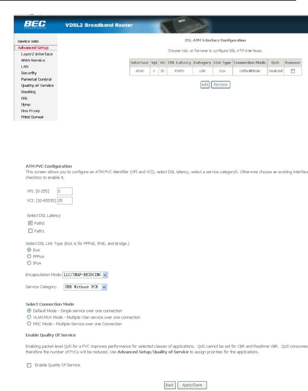
The value for VPI/VCI is assigned by your ISP. After inputing the PVC value, press “Apply/Save” to
save configuration. As Figure 3.3.
ZXDSL 831AII User Manual
- 12 -
Figure 3.3
The Modem supports five VDSL protocol modes. Choose the protocol which is appointed by ISP and PVC
encapsulation.
• PPP over ATM (PPPoA) • PPP over Ethernet (PPPoE)
• Bridging
Some connection lines need to confirm the LLC or VC, if you can’t confirm, please don’t modify the
default value or ask your ISP.
3.2 RFC1483 BRIDGE CONFIGURATION
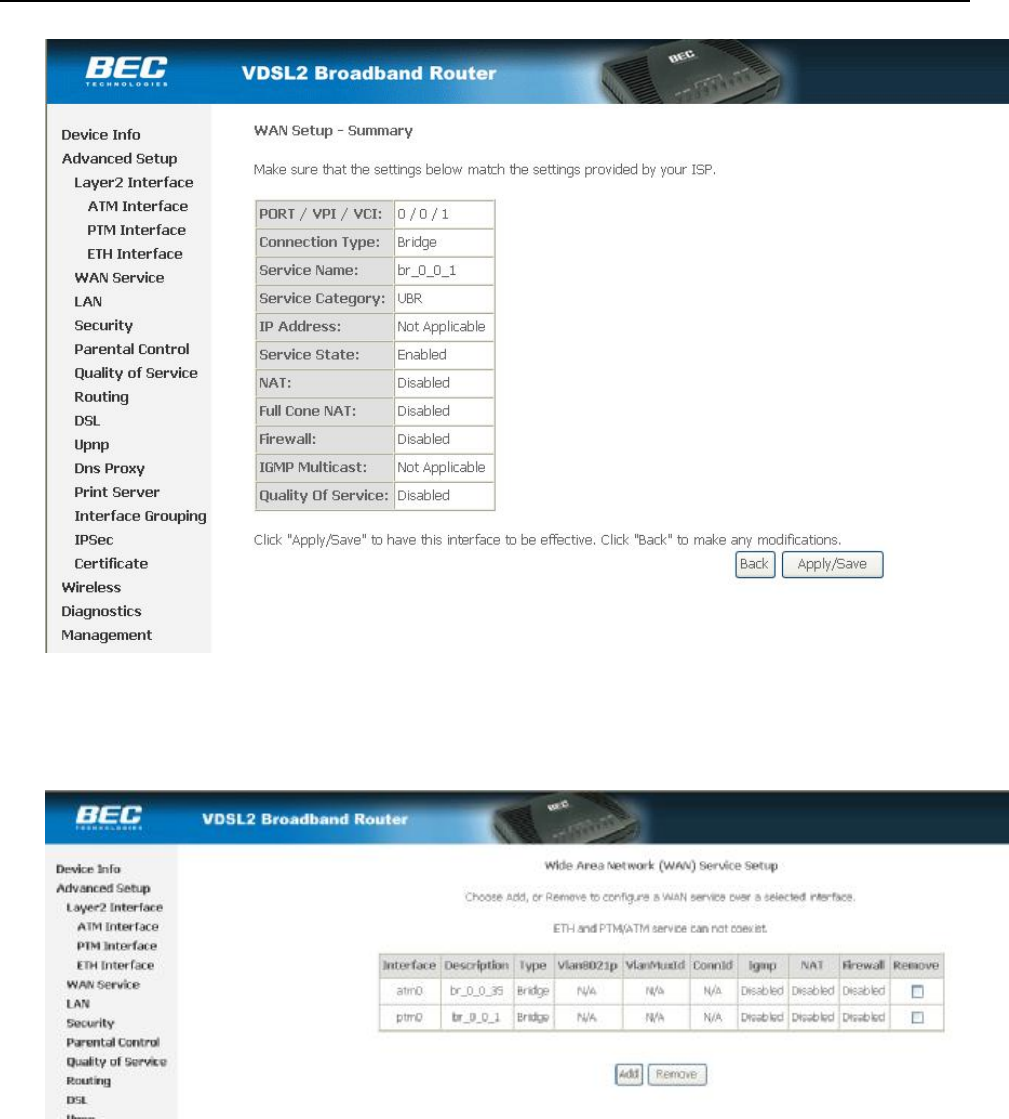
Click “Advanced Setup” on the left page, enter into “WAN Service Setup” page. As Figure 3.4.
Note: At most we can have eight connections. If you need to add a new connection, please delete or modify
an existing connection
ZXDSL 831AII User Manual
- 13 -
Figure 3.4
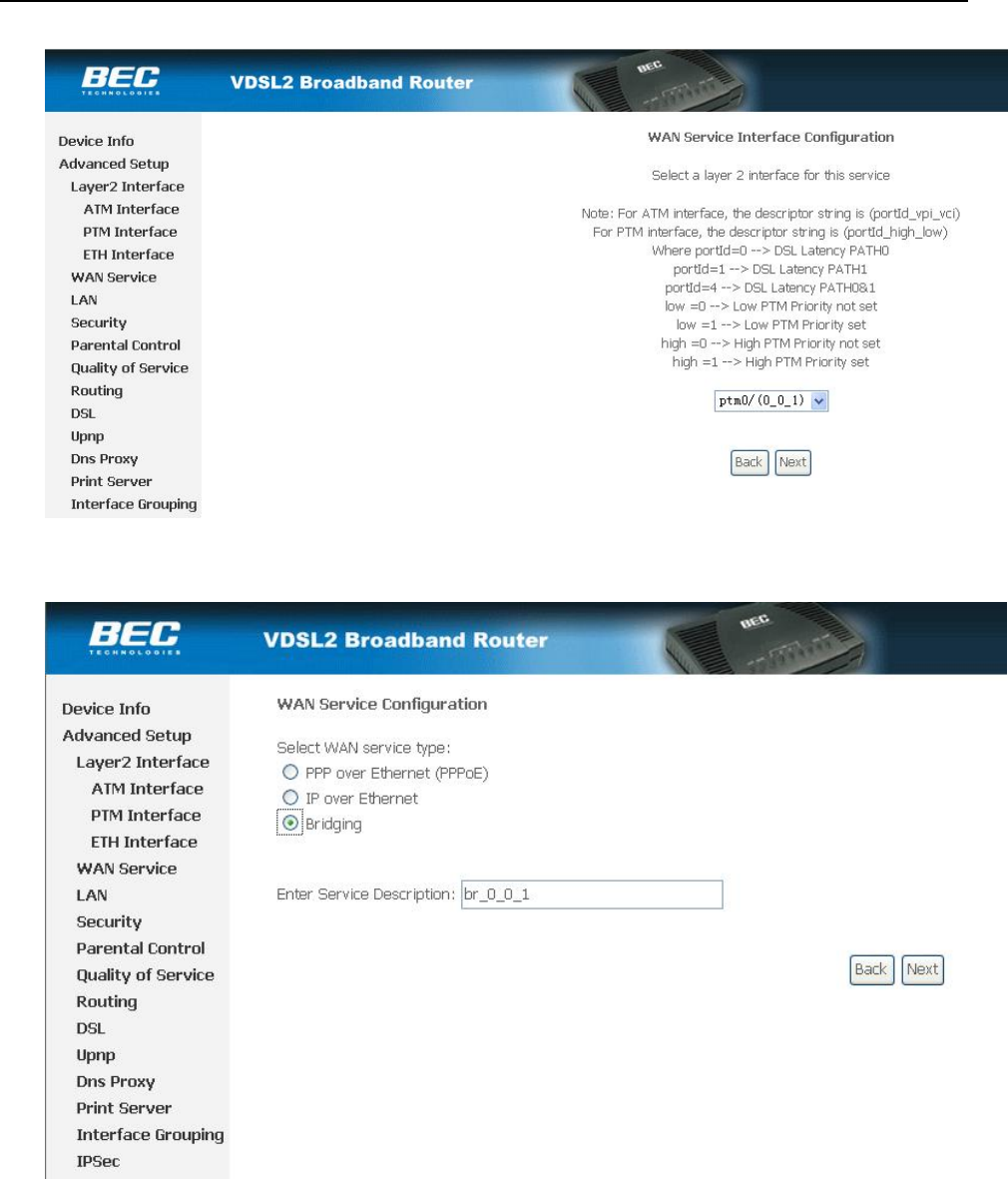
Press “Next” button, enter the configure guide, as Figure 3.5
Figure 3.5
Press “Next” button, enter the configure guide, as Figure 3.6
ZXDSL 831AII User Manual
- 14 -
Figure 3.6
Press “Apple/Save” to save your configuration,and you will see as following Figure 3.7.
.
Figure 3.7
3.3 PPPOA AND PPPOE CONFIGURATION
PPPoE is also known as RFC 2516. It is a method of encapsulating PPP packets over Ethernet.
PPPoA is also known as RFC2364 and named as Peer to Peer Protocol over ATM. As PPPoE, it also has all
the features of PPP. Although it’s based on ATM protocol, the setting of all the other parameters is similar with
PPPoE. So we only introduce PPPoE in detail here.
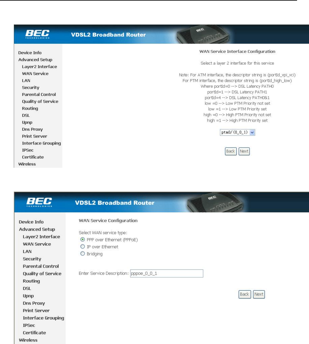
Click “Advanced Setup” on the left page, enter into “WAN Service Setup” page.
Note: At most we can have eight connections. If you need to add a new connection, please delete or modify
ZXDSL 831AII User Manual
- 15 -
an existing connection
Figure 3.8
Press “Next” button, enter the configure guide, as Figure 3.9
Figure 3.9
The value for VPI/VCI is assigned by your ISP.Press “Next” button, enter the configure guide, as Figure
3.10.
ZXDSL 831AII User Manual
- 16 -
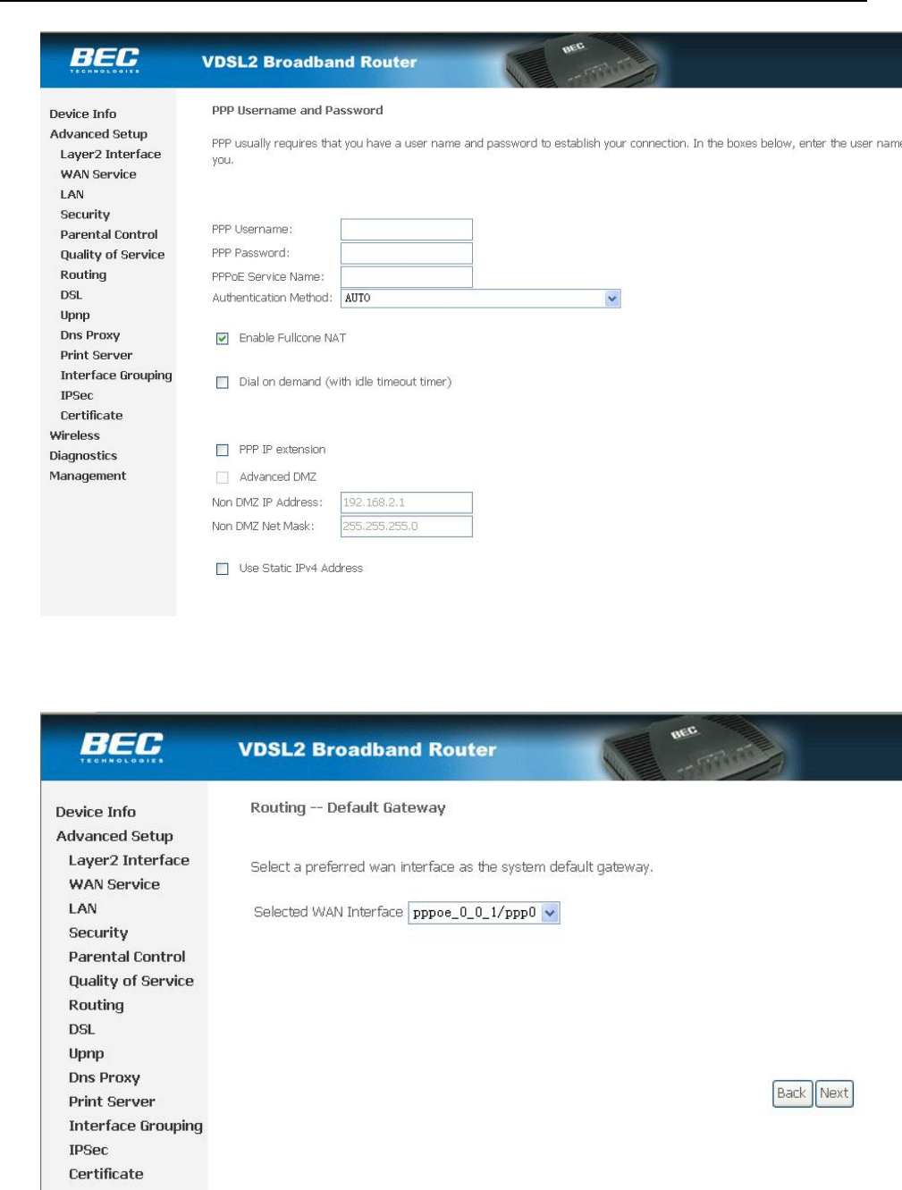
Figure 3.10
Ealble “Fullcone NAT “press “Next” to continue. As Figure 3.11.
Figure 3.11
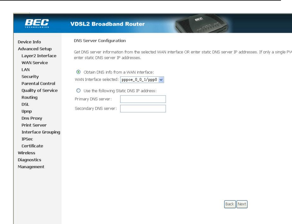
Press “Next” to continue. As Figure 3.12
ZXDSL 831AII User Manual
- 17 -
. Figure 3.12
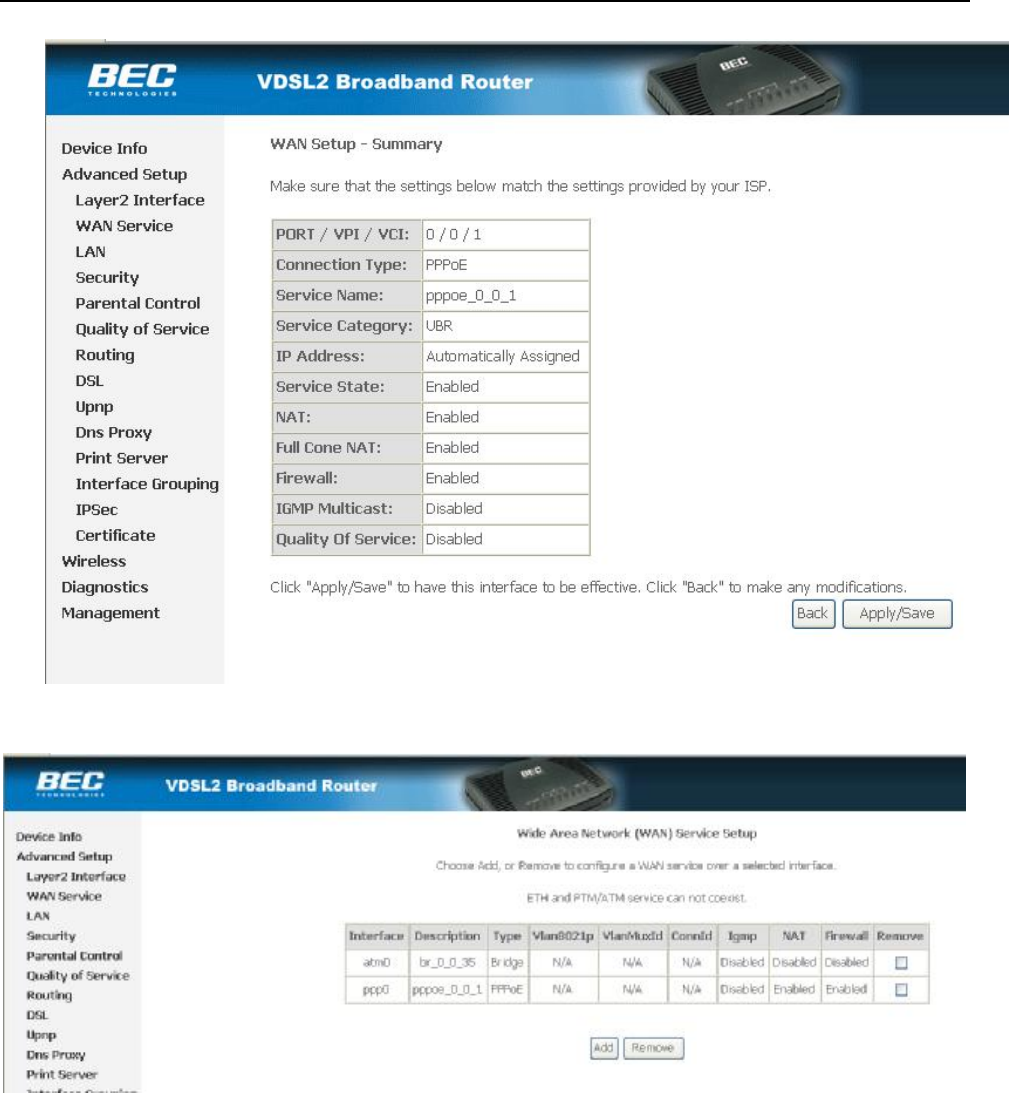
Configure your DNS info and press “Next” to save your configuration,and you will see as following Figure
3.13.
.
ZXDSL 831AII User Manual
- 18 -
Figure 3.13
Press “Apply/Save” to save your configuration. As Figure 3.14.
Figure 3.14
ZXDSL 831AII User Manual
- 19 -
4.1 TCP/IP PROTOCOL CONFIGURATION
1. Set IP address as “192.168.1.1”;
2. Set netmask as”255.255.255.0”;
4.2 MODEM CONFIGURATION
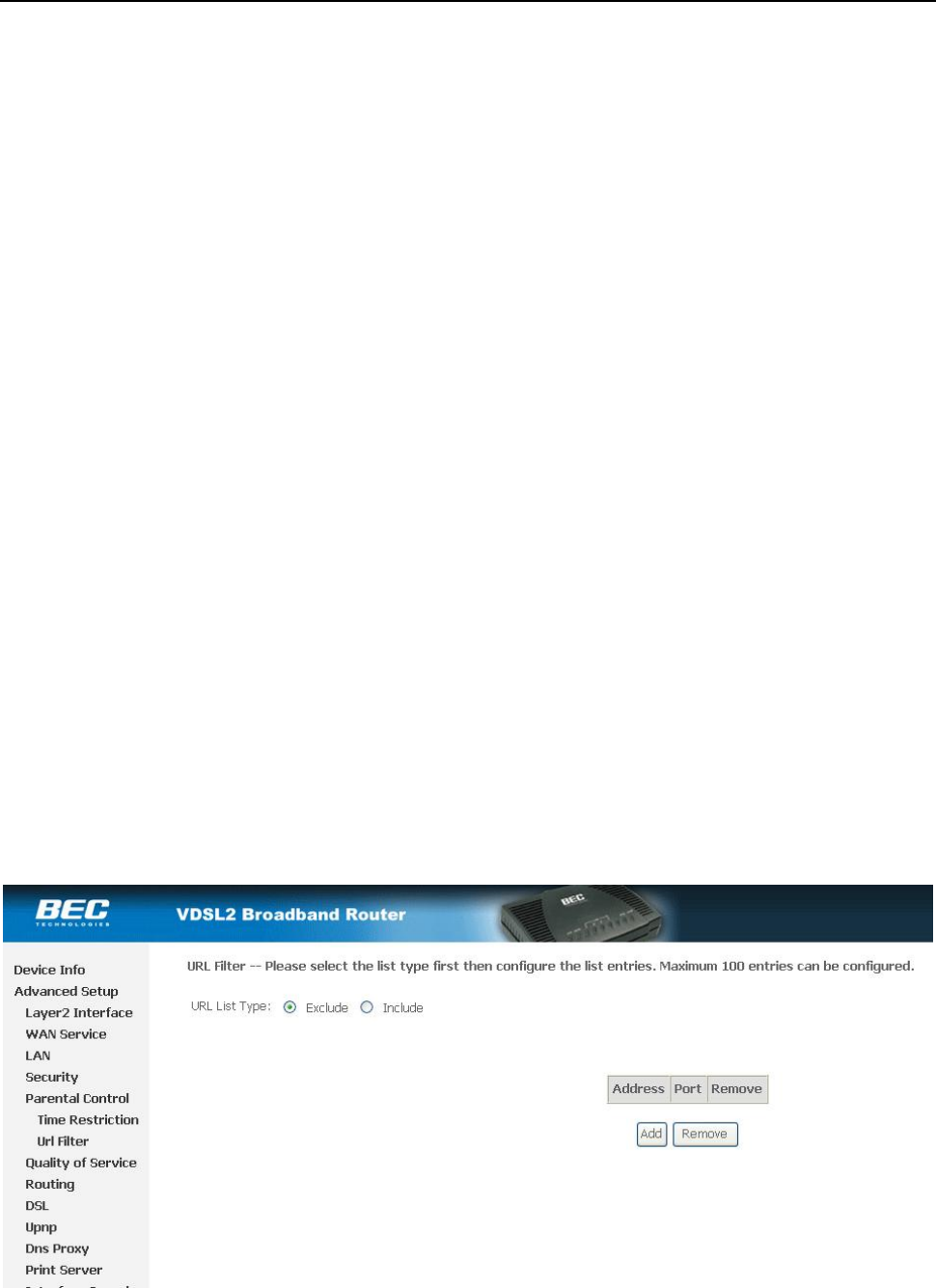
1. Click “Advanced Setup” on the left page, enter into “Url Filter” page, shown as Figure 4.1.
Figure 4.1
2. URL FILTER settings:
ZXDSL 831AII User Manual
- 20 -
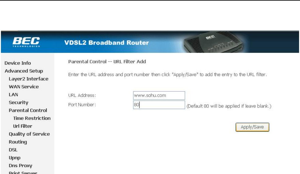
a) Choose Exclude or Include,then press “add” to add the url you want to configration.
b) Fill in the url and press Apply/Save to save your configration, shown as Figure 4.2
Figure 4.2
ZXDSL 831AII User Manual
- 21 -
5. OTHER FUNCTIONS AND CONFIGURATION
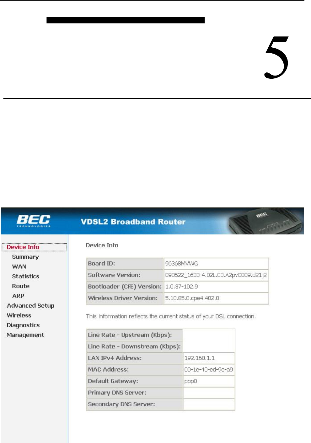
5.1 STATUS CHECKING
The working status of VDSL MODEM can be monitored by some pages.
1. Overview of Device Information
As shown in Figure 5.1, the information of hardware version, software version, DSL link status, link speed
and LAN interface can be viewed on this page.
OTHER FUNCTIONS AND
CONFIGURATION
ZXDSL 831AII User Manual
- 22 -
Figure 5.1
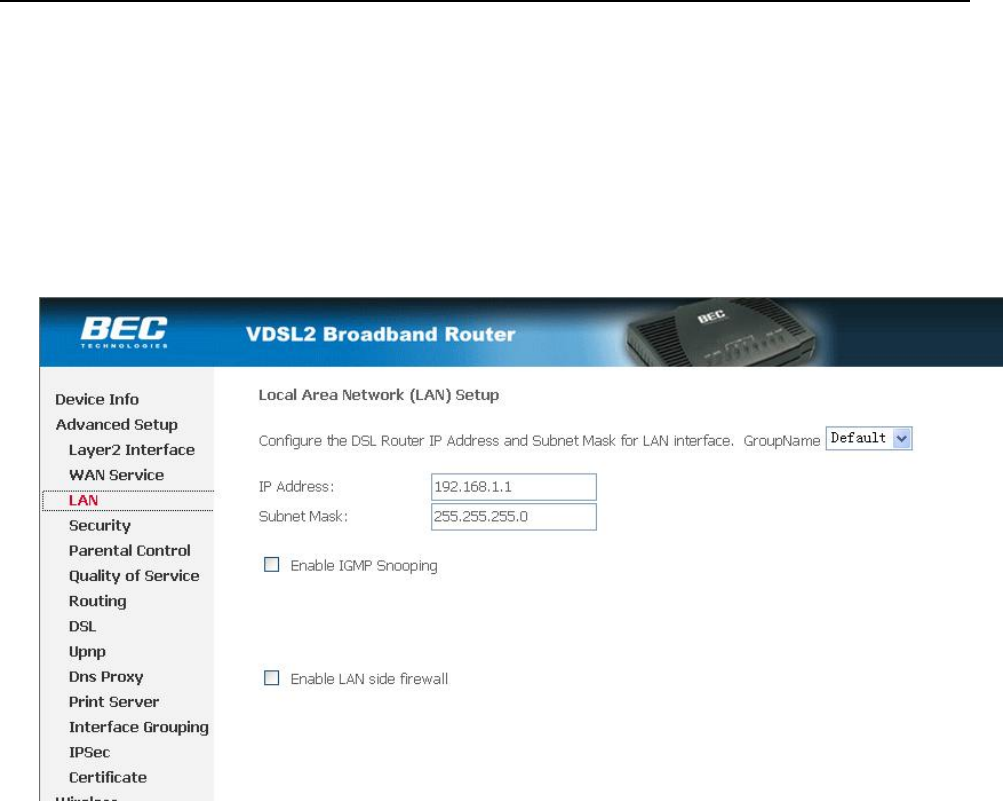
5.2 CONFIGURATION OF MODEM’S IP ADDRESS AND PASSWORD
1. CONFIGURATION OF MODEM’S IP ADDRESS
As a network device, VDSL Modem has its own IP address and MAC address. The factory sets the VDSL
Modem at a default IP address of 192.168.1.1 and subnet mask of 255.255.255.0. The user can configure these
addresses through the Local Network page as shown in Figure 5.2
Figure 5.2.
2. Configuration of administrator’s password and user’s password
When logging on the setting page of VDSL Modem, the system requires user name and password to verify
for permission. The default administrator’s account is “admin” and the default password for this account is
“admin”. The user, through the user configuration tab on page Management, can change the passwords.
(Attention: please remember the password after changing otherwise you will not be able to change
configuration after saving.)
ZXDSL 831AII User Manual
- 23 -
6. RESET TO DEFAULT SETTING
If you are experiencing difficulty logging on to the configuration page (For example: you forget the
password), you can reset the VDSL MODEM to the default configuration,Then you will be able to log on with
the default username and password.
Method:
Turn on the VDSL MODEM, put a pin into the eyelet, and press only once.
RESET TO DEFAULT SETTING

ZXDSL 831AII User Manual
- 24 -
7. USAGE OF USB INTERFACE
The Combo DSL Gateway is a device with both Ethernet Interface and USB Interface, which is
independent, you may use either of them to connect to the different computers, in this way the two computers
can connect to the network at one time. The Gateway can be seen as a simple two-port HUB. So, do not
connect both the Ethernet Interface and USB Interface to a same computer.
When using USB Interface, you must install the drivers. After installation, a virtual network card, "USB
Remote NDIS Network Device", will be added into the computer. It has all the functions of a real network
card, and it makes installation more easily.
NOTES:
The following shows the steps for Windows®2000, the installation, configuration and uninstallation of
Windows®98 or Windows®XP are similar to this.
7.1 DRIVER INSTALLATION
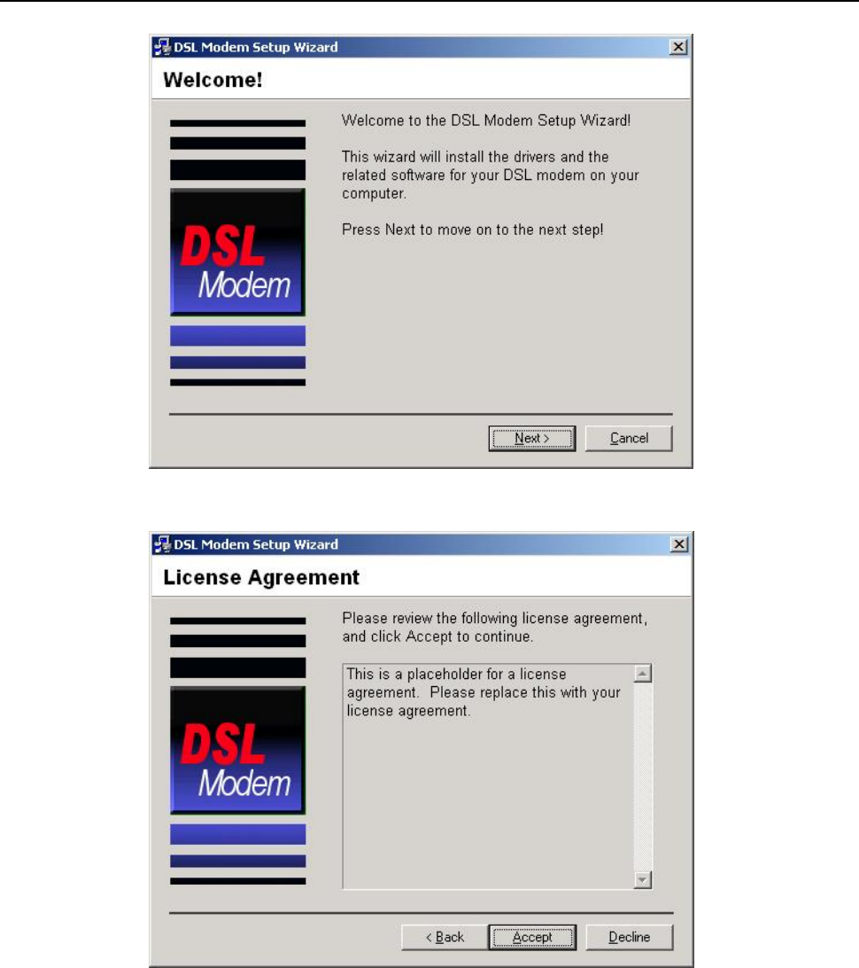
1. Open the Modem, and connect the USB port. Then double click “Setup.exe” in “G:\Driver\” . You will
enter the DSL MODEM Setup Wizard as figure 7.1.1, click “Next”.
USAGE OF USB INTERFACE
ZXDSL 831AII User Manual
- 25 -
Figure 7.1.1
2. A new dialog box will show you a figure 7.1.2. Click “Accept” to continue.
Figure 7.1.2
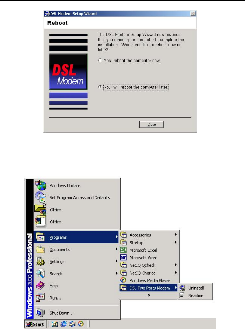
3. A new box will show whether you want to reboot the computer. Choose “No, I will reboot the computer later”,
then click “close” button to finish the installing.
ZXDSL 831AII User Manual
- 26 -
Figure 7.1.3
7.2 UNINSTILL DRIVER
1.Click “Start” à “Programs” à “DSL Two Ports MODEM” à “Uninstall”. As shown figure 7.2.1.
Figure 7.2.1
ZXDSL 831AII User Manual
- 27 -
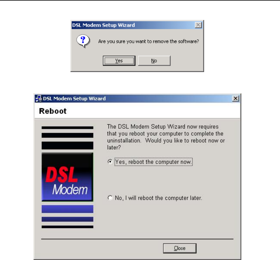
2. It will ask you to click“Yes” to confirm deletion. As shown figure 7.2.2.
Figure 7.2.2
3.Choose “Yes, reboot the computer now”. As shown figure 7.2.3.
Figure 7.2.3
7.3 CONFIGURATION OF "USB IAD LAN MODEM"
As a virtual network card, "USB IAD LAN MODEM " can be configured as a normal network card.
Set the computer IP address at same segment of VDSL MODEM, such as set the IP address of the network
card to one of the “192.168.1.3”~ “192.168.1.254”.
User can also change its configuration for special reason.
ZXDSL 831AII User Manual
- 28 -
Figure 7.3.1

ZXDSL 831AII User Manual
- 29 -
8. SPECIFICATION
8.1 POWER SUPPLY
l Exterior power adapter
l Input: 220VAC, 50Hz
l Output: 12VDC.
l Polarity:
8.2 STANDARDS
l EMI/Immunity: FCC Part 15 Class B, CE Mark (EN55022 Class B/EN50082)
l Safety Standard: UL, EN60950, 3C
l Communication: FCC Part 68, CYR21
l Electromagnetic: in accordance with FCC, ETSI and CISPR standard
8.3 ENVIRONMENT REQUIREMENTS
l Temperature: 5℃-40℃(41F-104F)
l Relative humidity:30%-90%
l Electromagnetic disturbance:FCC PART15&68
SPECIFICATION

ZXDSL 831AII User Manual
- 30 -
APPENDIX
APPENDIX A. TROUBLESHOOTING
Phenomena Solution
The indicator of power
supply is not on
1. Make sure the connection of power supply is good.
2. Make sure the switch of power supply is turned on.
3. Make sure the output of power supply is correct.
The indicator of PC is not
on
1. Check the connection between the cable and the network card.
2. Make sure that the correct cable is used.
3. Make sure the cable works fine by pinging the host IP address.
Can not access Internet or
remote networks
1. Make sure the problems listed above are eliminated.
2. Make sure the software configuration of the VDSL Modem is
correct.
3. Make sure you have restarted the VDSL Modem after
configuration change.
4. Check IP connection using ping command.
5. Make sure the DNS of the computer is correct.
Can’t access some web
server
1. The MTU of operating system might be too large.
2. Some operating systems might need to be patched.
Can not log on to the
configuration page
1. Make sure the PC indicator is on.
2. Make sure the configuration of TCP/IP is correct.
3. Make sure the data indicator of Modem is on when using Ping
command.
4. Make sure the user name and password is correct.
5. Reset the device.
APPENDIX
ZXDSL 831AII User Manual
- 31 -
APPENDIX B. SPLITTER CONNECTION
1. Splitter
2. Connection
Firstly, use a telephone cord to connect the LINE port of the splitter and the RJ-11 port (the phone jack) on
the wall. Then use another telephone cord to connect the VDSL port of the splitter and the LINE port of the
VDSL Modem. Finally, use another telephone cord to connect the telephone set and the PHONE port of the
splitter.
Power
Interface
Line
Interface
Ethernet
Interface USB
Interface
ZXDSL 831AII User Manual
- 32 -
APPENDIX C. CONFIGURATION OF TCP/IP PROTOCOL
Here we will explain the configuration which using Windows 2000 operation system as an example.
For other operation systems the process is similar.
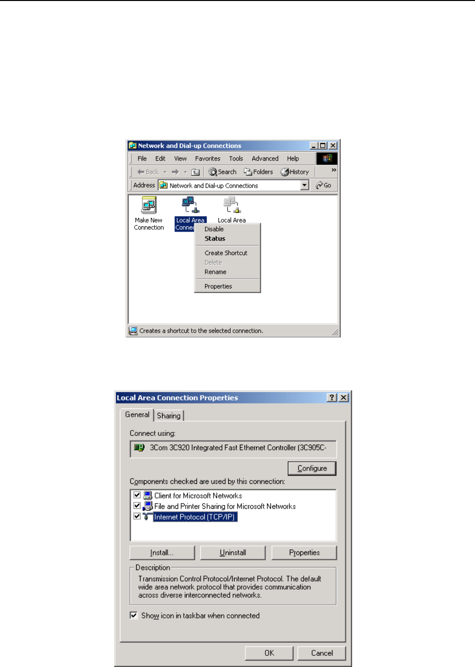
1. Right click on the “Local Area Connection”, click “Properties” on the pop up menu, as shown in Figure
C.1.
Figure C.1
2. The dialog box of networks is shown in Figure C.2. On the “General” property page select “Internet
Protocol(TCP/IP)”,and then click the “Properties” button.
Figure C.2
ZXDSL 831AII User Manual
- 33 -
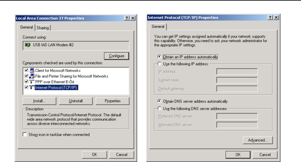
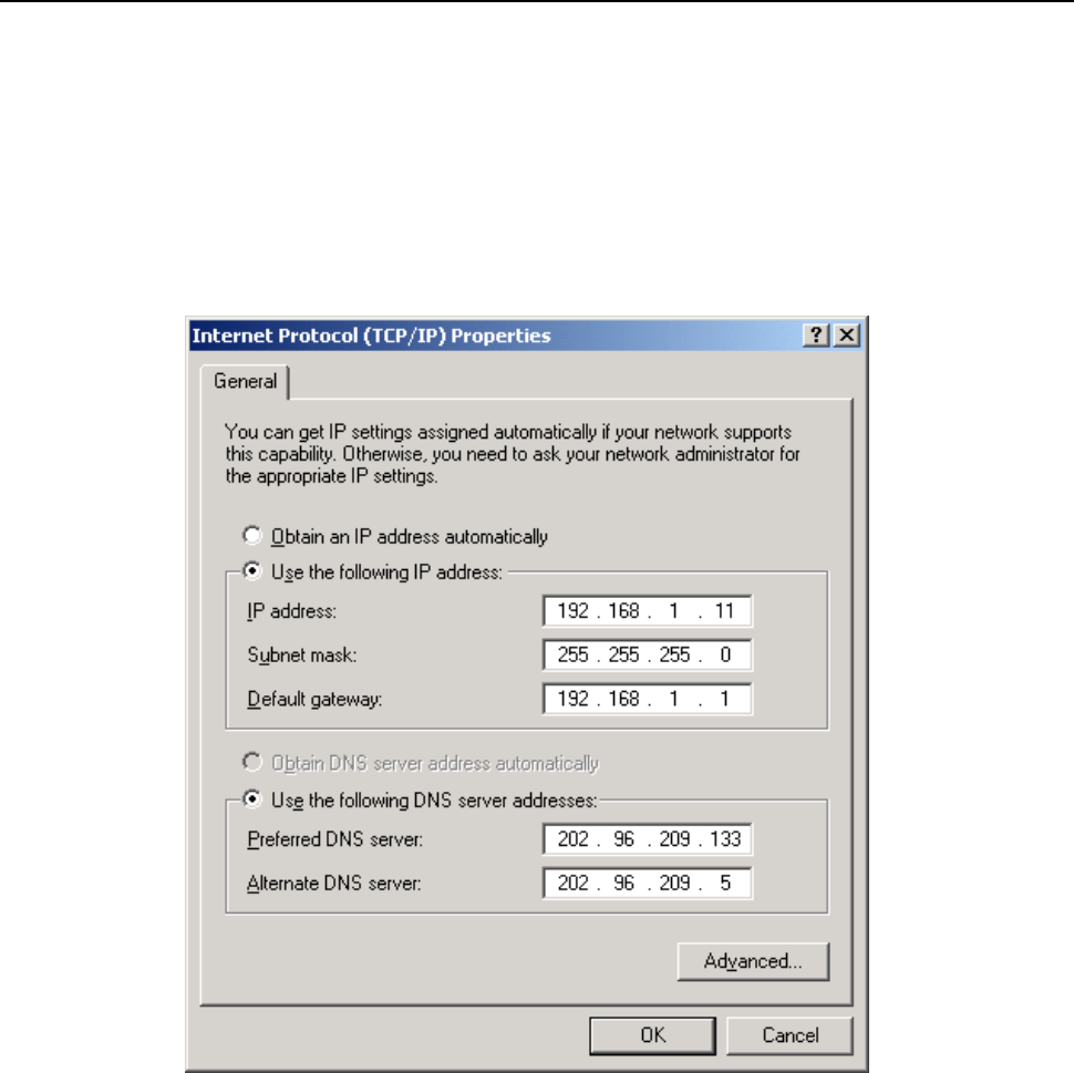
3. The “Internet Protocol (TCP/IP) properties” pop up window is shown as Figure C.3. Select “Use the
following IP address”. Input the following IP address: 192.168.1.11 and subnet mask: 255.255.255.0
(These addresses and subnet mask are similar with the factory default setting. The user can set different IP
address and subnet mask whenever necessary). Select “Gateway”, input the default IP address of the
gateway: 192.168.1.1 and IP address of Preferred DNS server: 202.96.209.133 (you can use your ISP’s
address), IP address of Alternate DNS server: 202.96.209.5(you can use your ISP’s address). The result is
shown in Figure C.3.
Figure C.3
4. Click “OK” button to return to the “Local Area Connection Property” dialog box.
5. Click “OK” button to close the Network property dialog box.

ZXDSL 831AII User Manual
- 34 -
APPENDIX D. SHIPPING LIST
Make sure the following items are included in the box. If any one of them is missing, please
contact the vendor immediately.
VDSL MODEM ×1
User Manual ×1
Telephone Line(RJ-11) ×2
Power Adapter ×1
USB Line ×1
Cable Cat5 RJ45 ×1
User CD ×1
Splitter ×1

ZXDSL 831AII User Manual
- 35 -
FCC INFORMATION
This equipment complies with CFR 47, Part 15.19 of the FCC rules. Operation of the equipment is subject to the following
conditions: (1) this device may not cause harmful interference, and (2) this device must accept any interference received; including
interference that may cause undesired operation.
THIS DEVICE MUST NOT BE CO-LOCATED OR OPERATING IN CONJUNCTION WITH ANY OTHER ANTENNA
OR TRANSMITTER
NOTE: THE MANUFACTURER IS NOT RESPONSIBLE FOR ANY RADIO OR TV INTERFERENCE CAUSED BY
UNAUTHORIZED MODIFICATIONS TO THIS EQUIPMENT. SUCH MODIFICATIONS COULD VOID THE USER’S
AUTHORITY TO OPERATE THE EQUIPMENT.
Federal Communications Commission (FCC) Requirements, Part 15
This equipment has been tested and found to comply with the limits for a class B digital device, pursuant to part 15 of the FCC
Rules. These limits are designed to provide reasonable protection against harmful interference in a residential installation.
This equipment generates, uses and can radiate radio frequency energy and, if not installed and used in accordance with the
instructions, may cause harmful interference to radio communications. However, there is no guarantee that interference will not
occur in a particular installation. If this equipment does cause harmful interference to radio or television reception, which can be
determined by turning the equipment off and on, the user is encouraged to try to correct the interference by one or more of the
following measures:
---Reorient or relocate the receiving antenna.
---Increase the separation between the equipment and receiver.
---Connect the equipment into an outlet on a circuit different from that to which the receiver is connected.
---Consult the dealer or an experienced radio/TV technician for help.
REGULATORY INFORMATION / DISCLAIMERS
Installation and use of this Wireless LAN device must be in strict accordance with the instructions included in the user
documentation provided with the product. Any changes or modifications (including the antennas) made to this device that are not
expressly approved by the manufacturer may void the user’s authority to operate the equipment. The manufacturer is not
responsible for any radio or television interference caused by unauthorized modification of this device, or the substitution of the
connecting cables and equipment other than manufacturer specified. It is the responsibility of the user to correct any interference
caused by such unauthorized modification, substitution or attachment. Manufacturer and its authorized resellers or distributors will
assume no liability for any damage or violation of government
CAUTION: To maintain compliance with FCC’s RF exposure guidelines, this equipment should be installed and operated with
minimum distance 20cm between the radiator and your body. Use on the supplied antenna. Unauthorized antenna, modification, or
attachments could damage the transmitter and may violate FCC regulations.
MPE Statement (Safety Information)
Your device contains a low power transmitter. When device is transmitted it sends out Radio Frequency (RF) signal.
SAFETY INFORMATION
In order to maintain compliance with the FCC RF exposure guidelines, this equipment should be installed and operated with
minimum distance 20cm between the radiator and your body. Use only with supplied antenna. Unauthorized antenna, modification,
or attachments could damage the transmitter and may violate FCC regulations.
Please use the factory recommended
power supply.