ADTRAN SR552N 802.11n VDSL2 Bonded Gateway User Manual Manual r1
SmartRG, Inc. 802.11n VDSL2 Bonded Gateway Manual r1
UserManual.wiki
>
ADTRAN
>
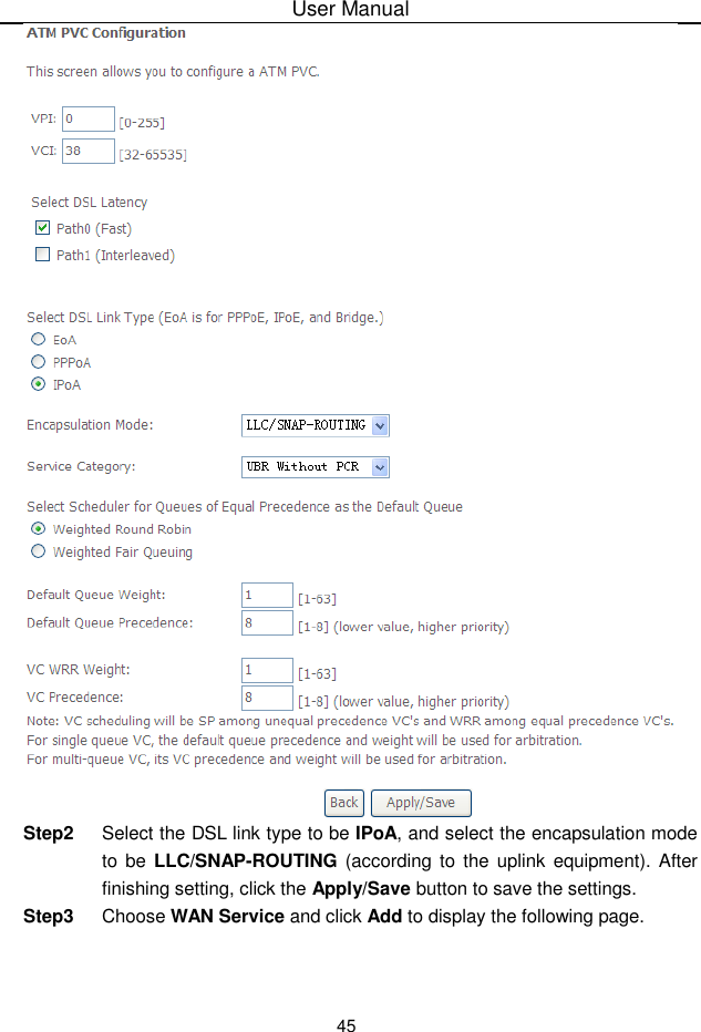
SR552N User Manual
Manual r1
Navigation menu
Upload a User Manual
Namespaces
Wiki Guide
HTML
PDF
Info
Views
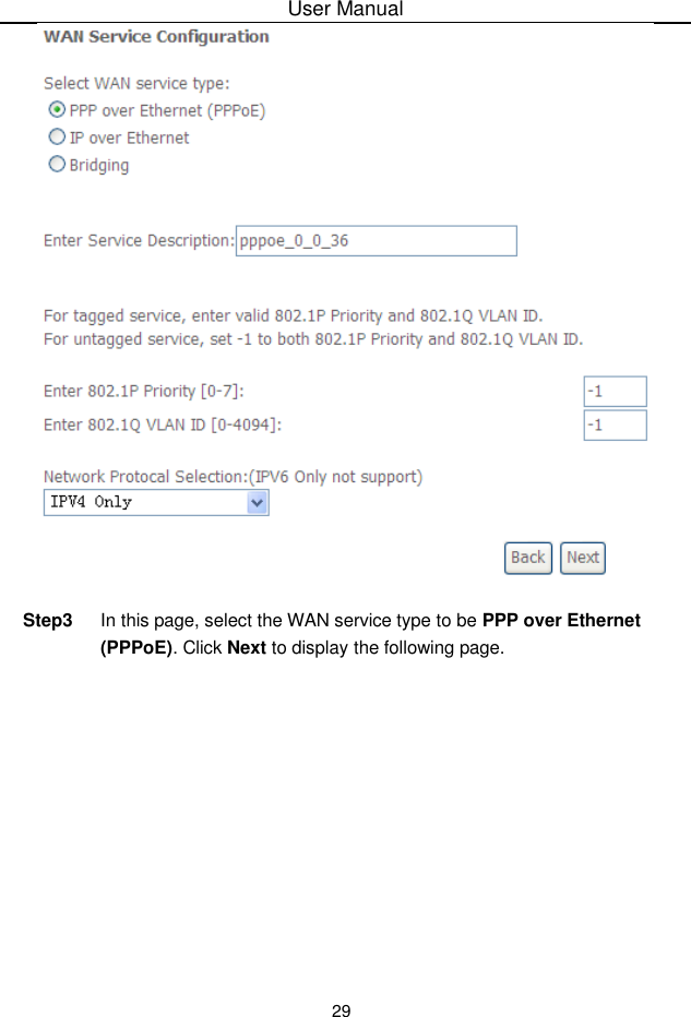
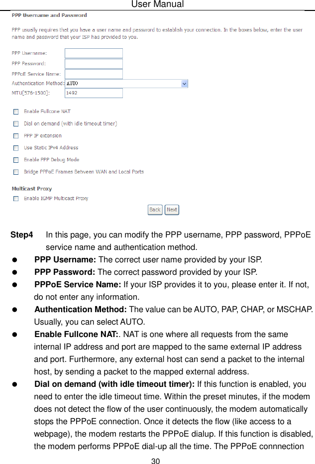
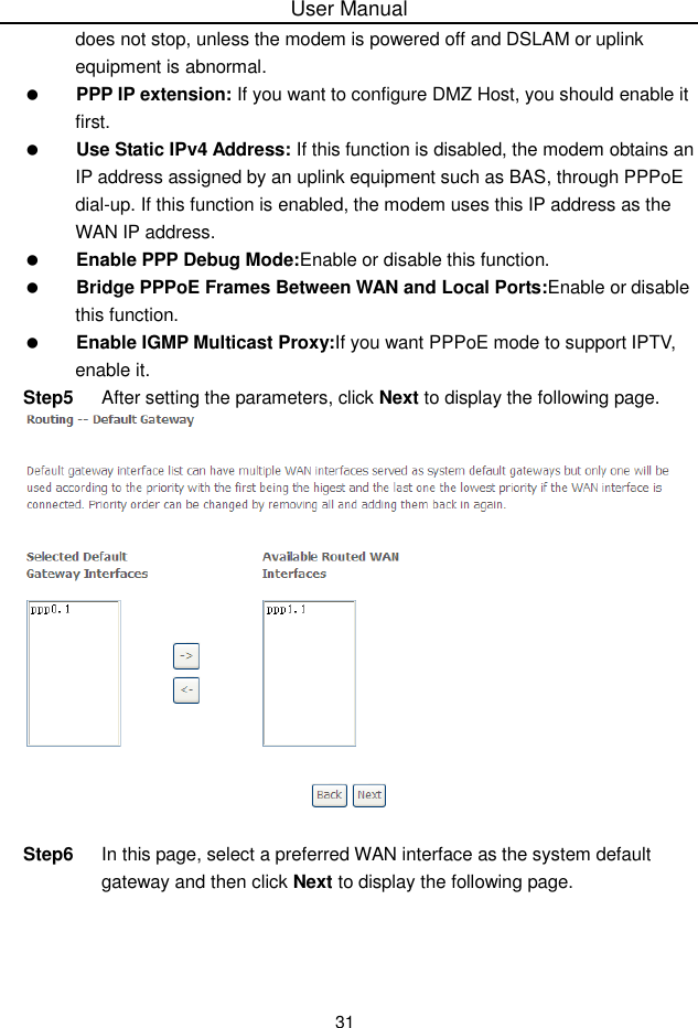
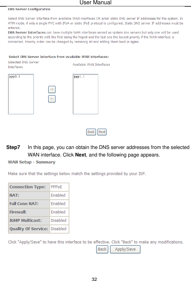
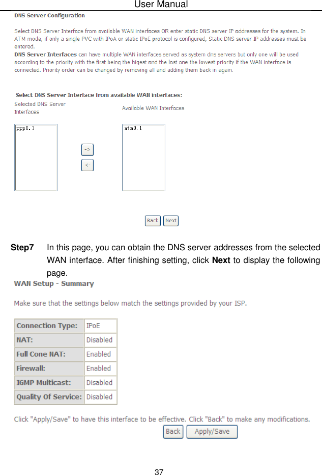
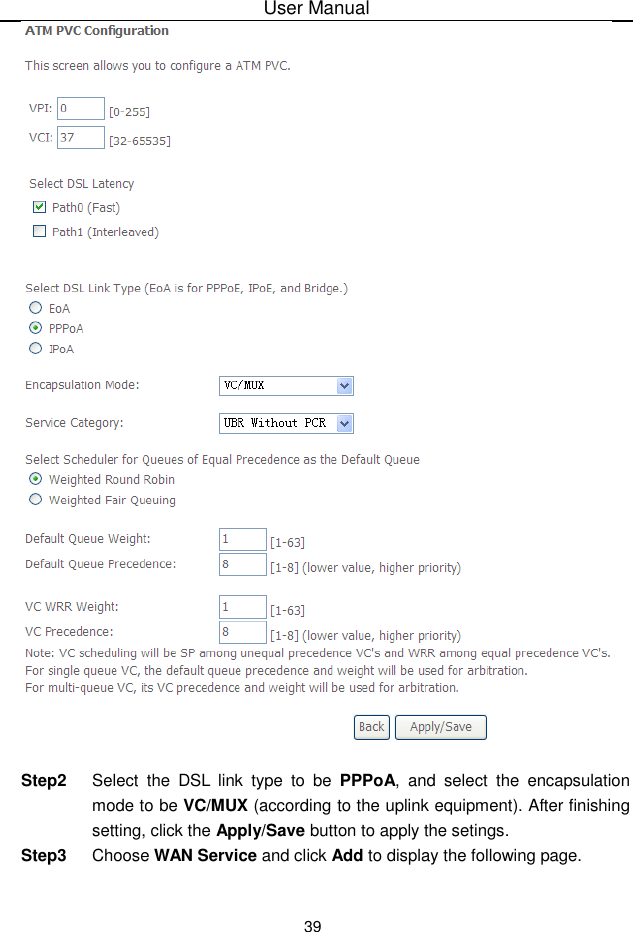
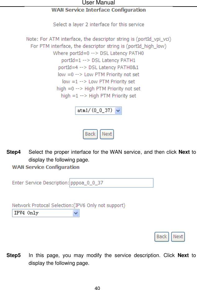
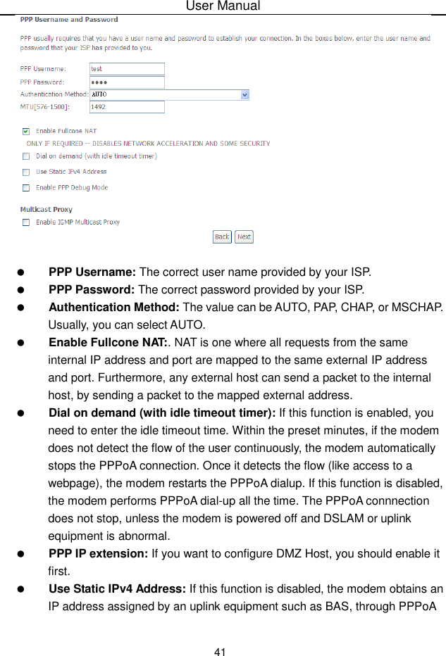
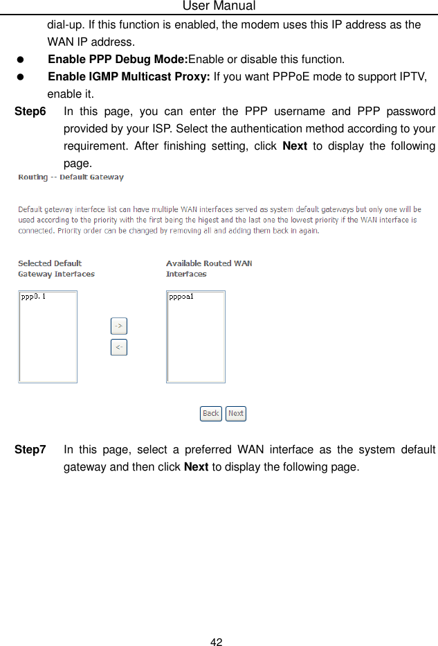
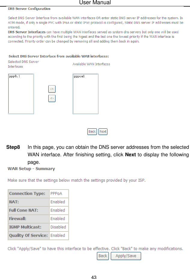
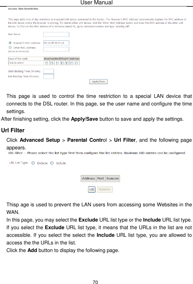
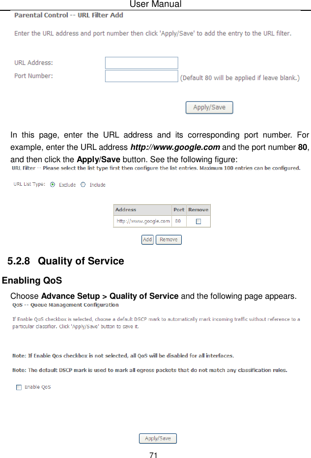
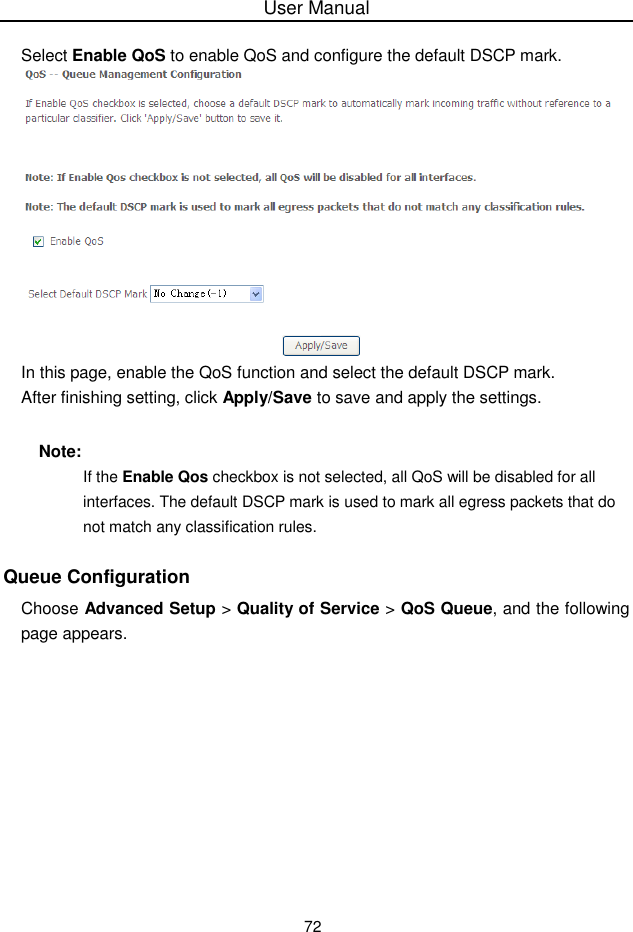
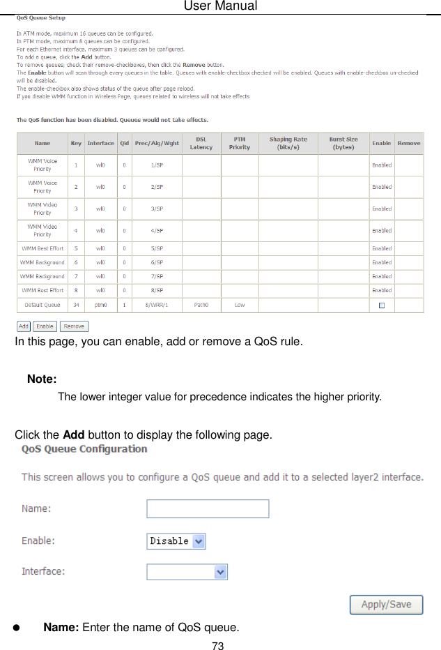
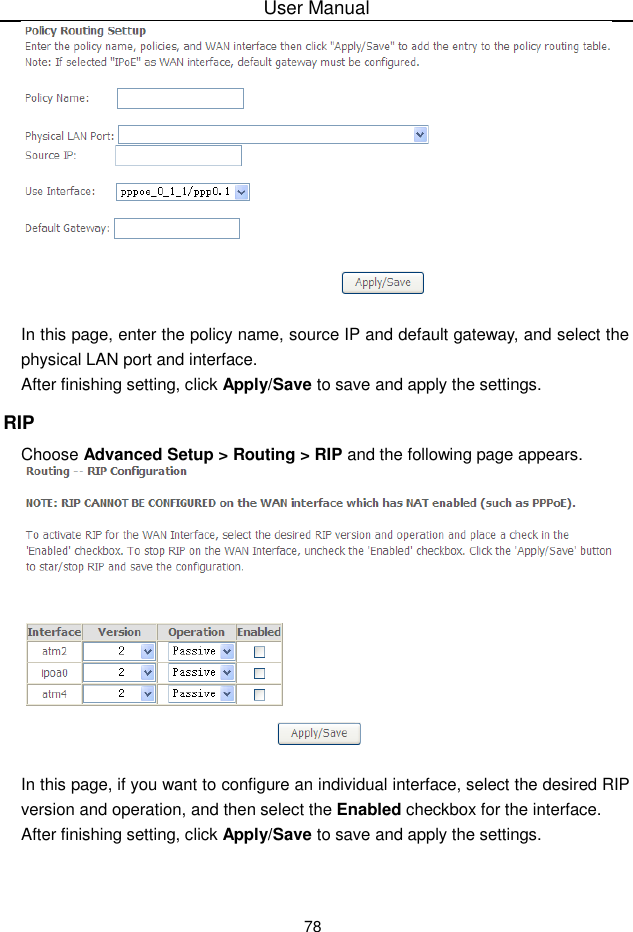
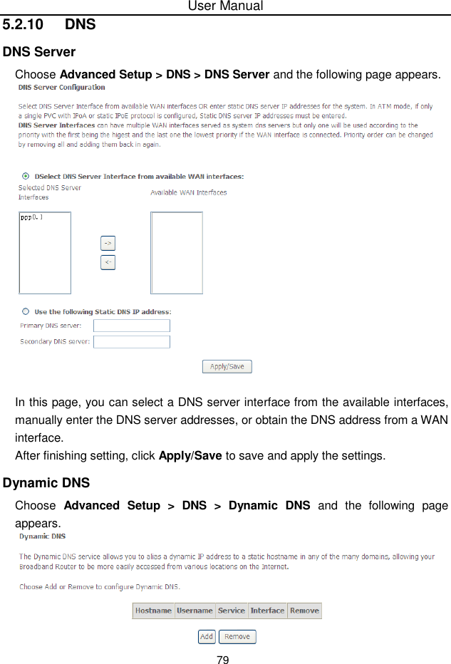
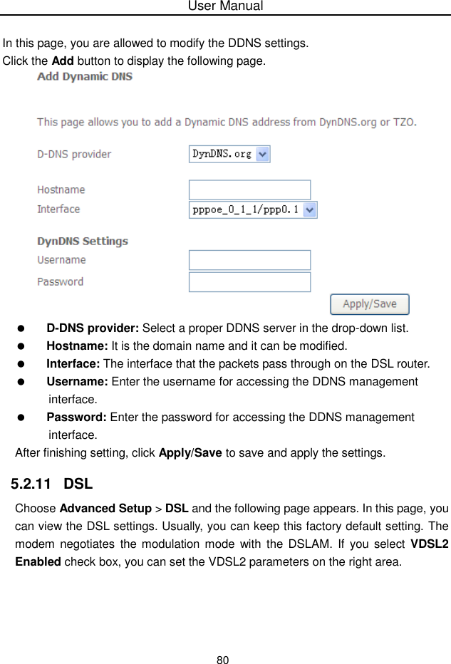
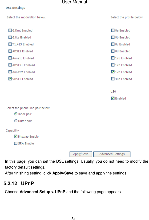
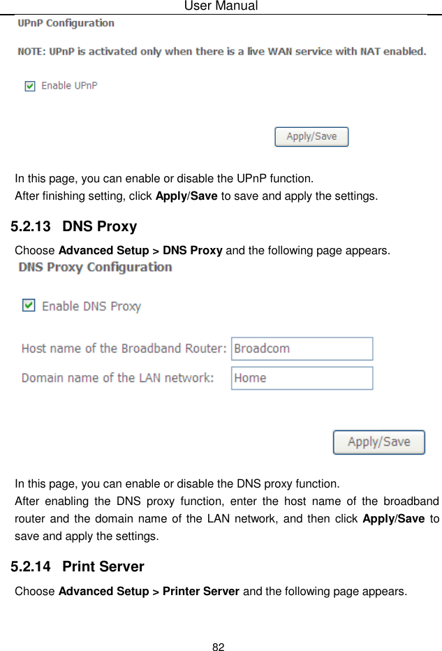
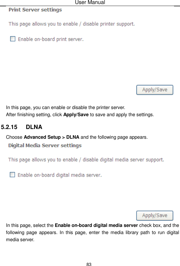
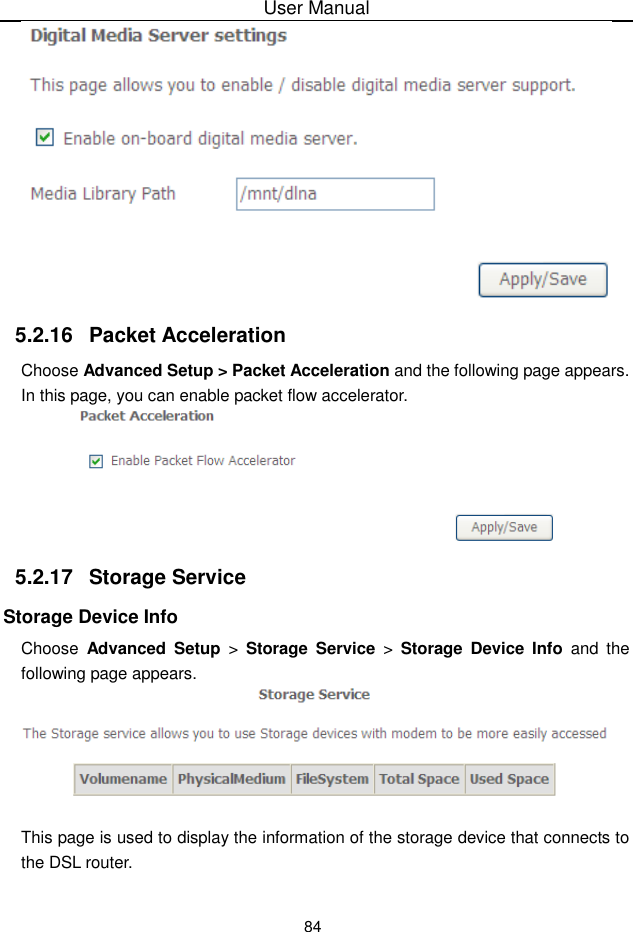
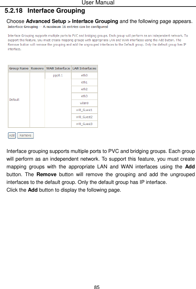
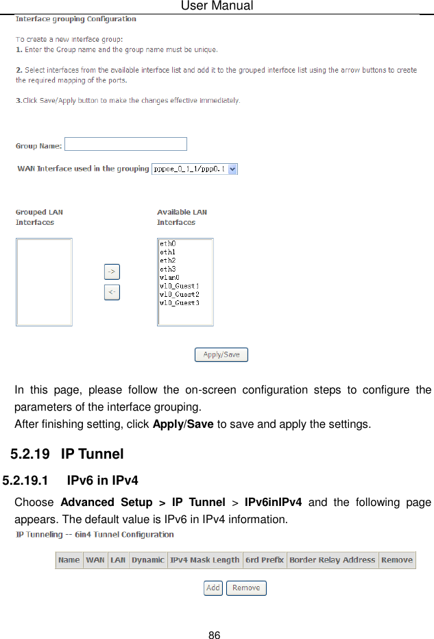
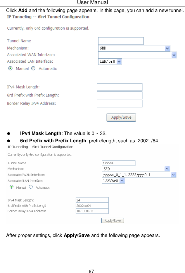
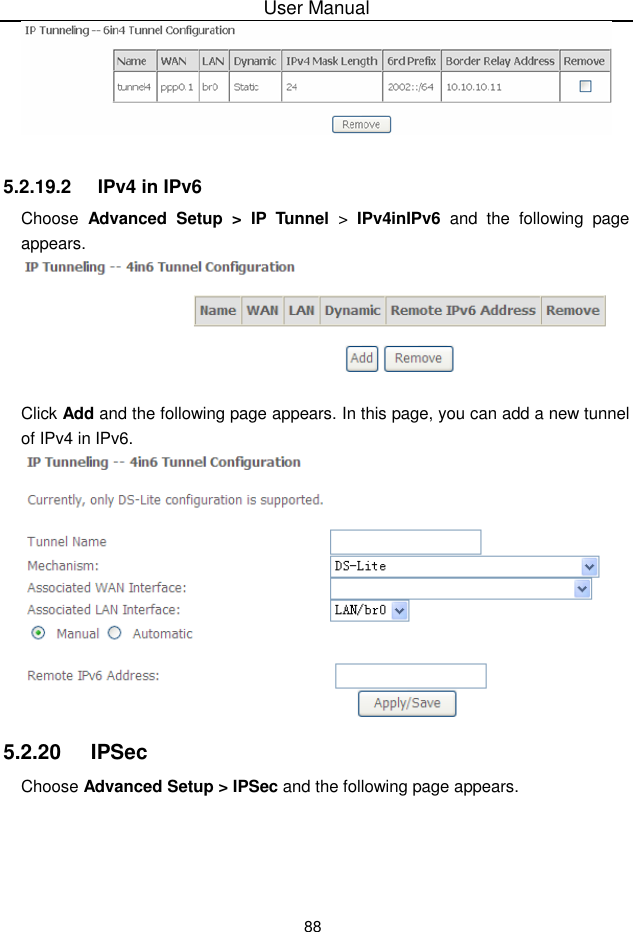
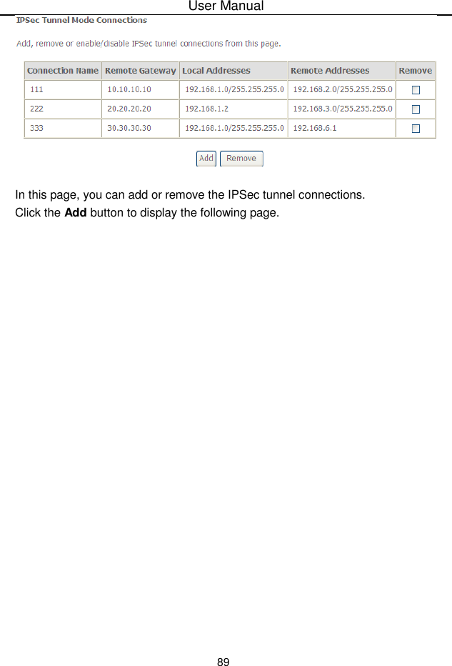
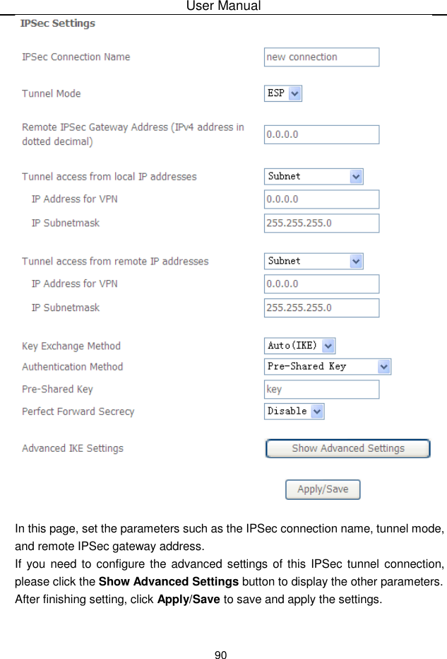
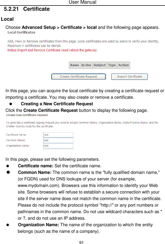
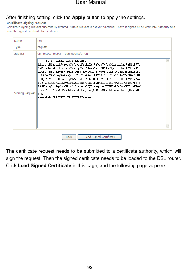
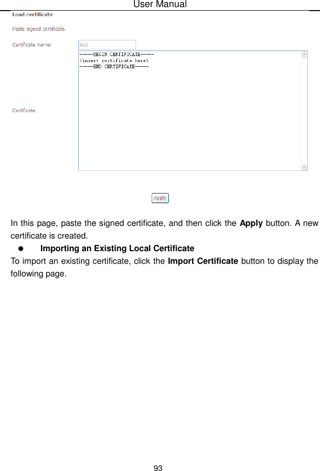
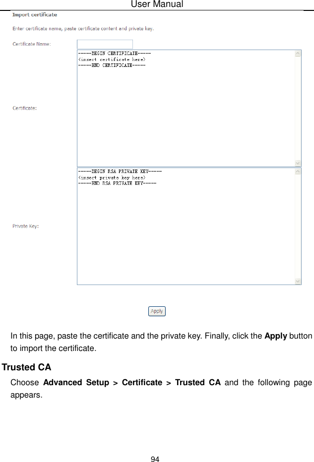
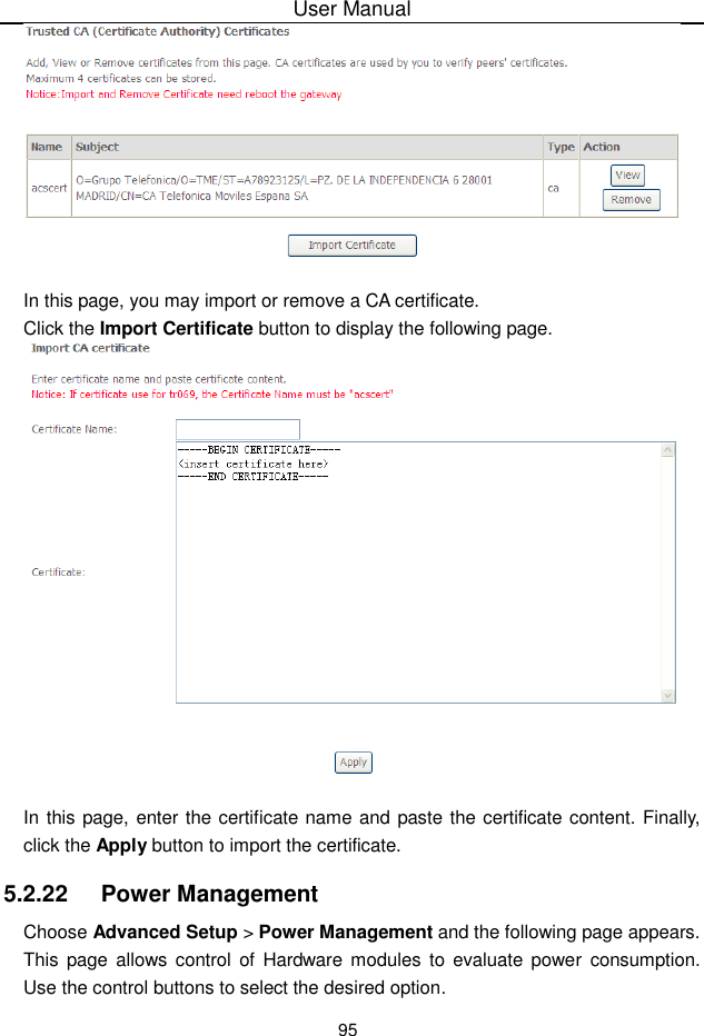
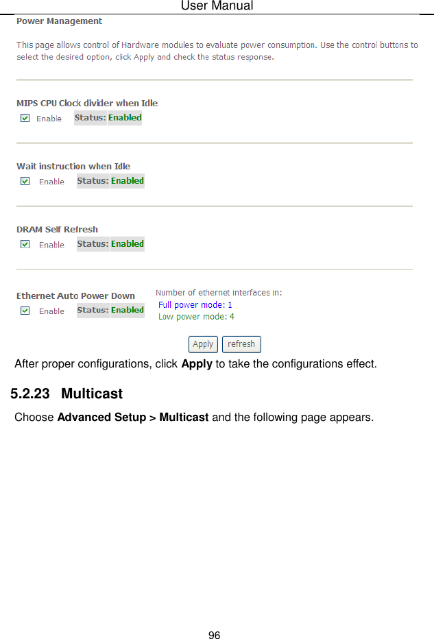
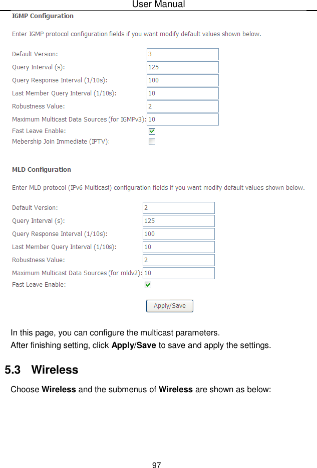
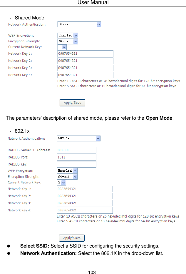
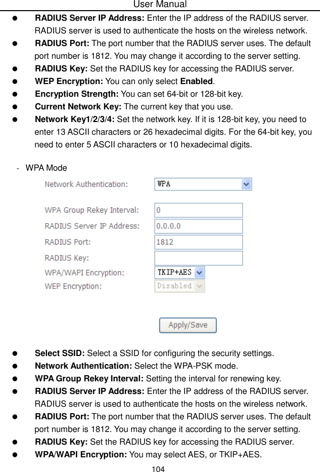
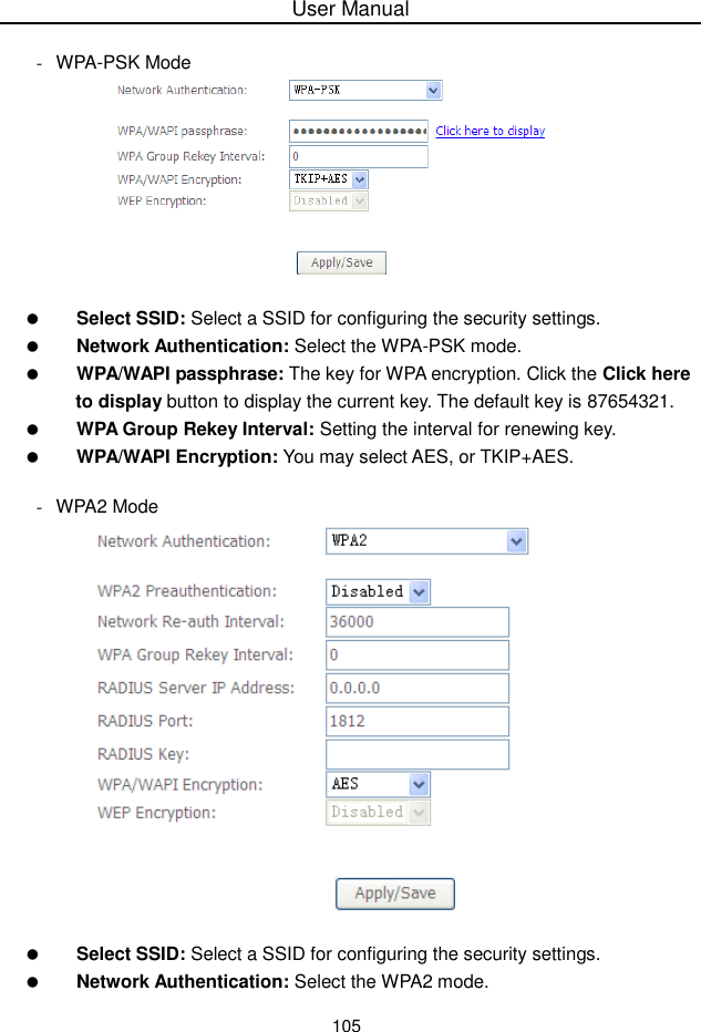
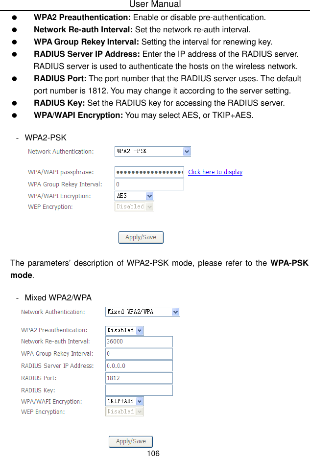
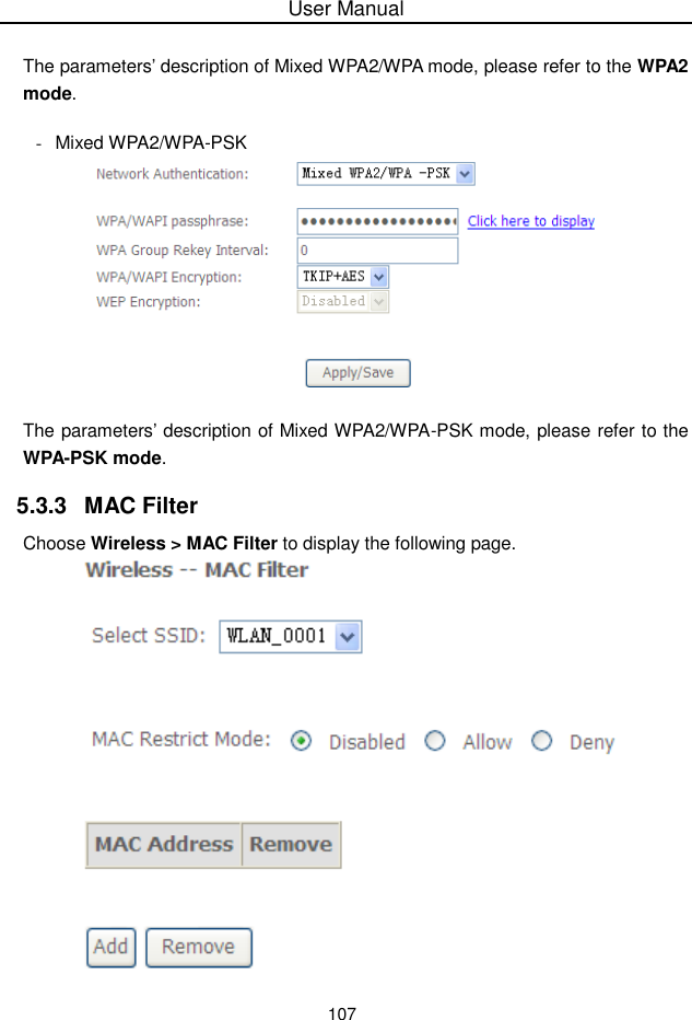
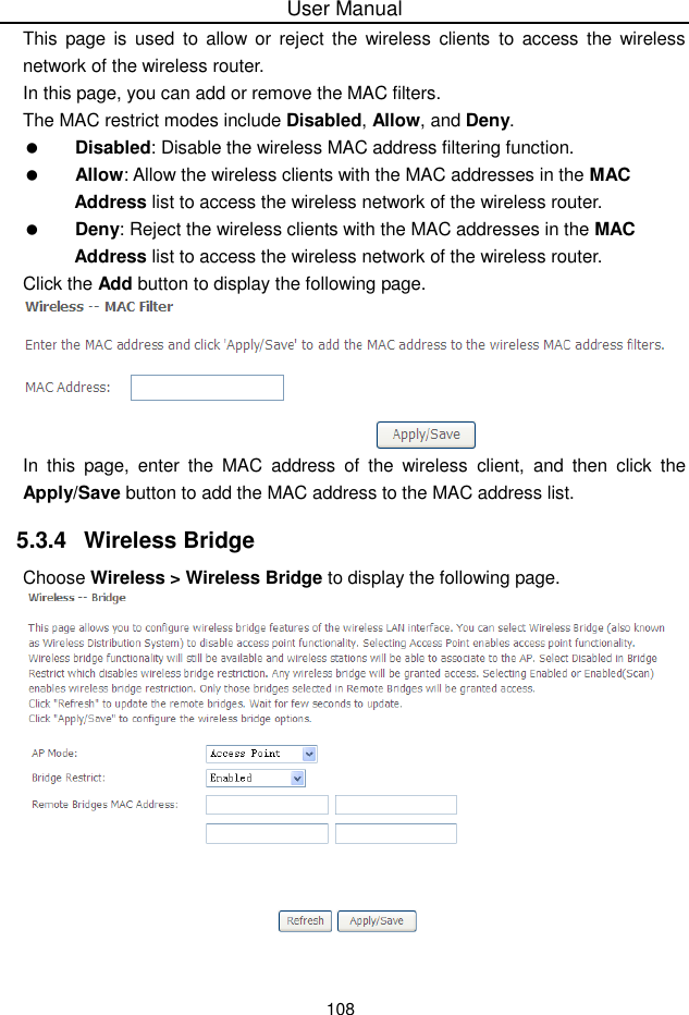
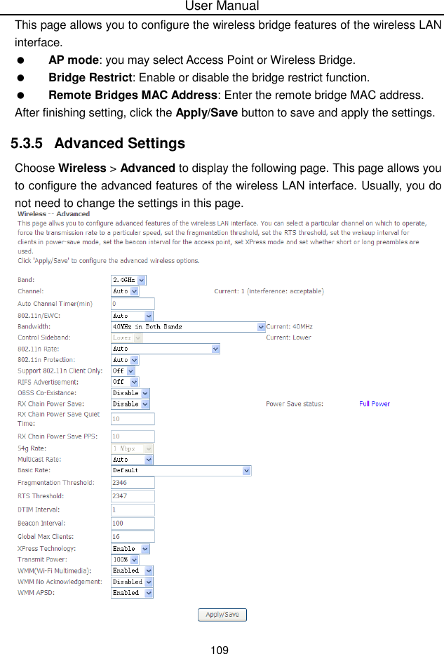
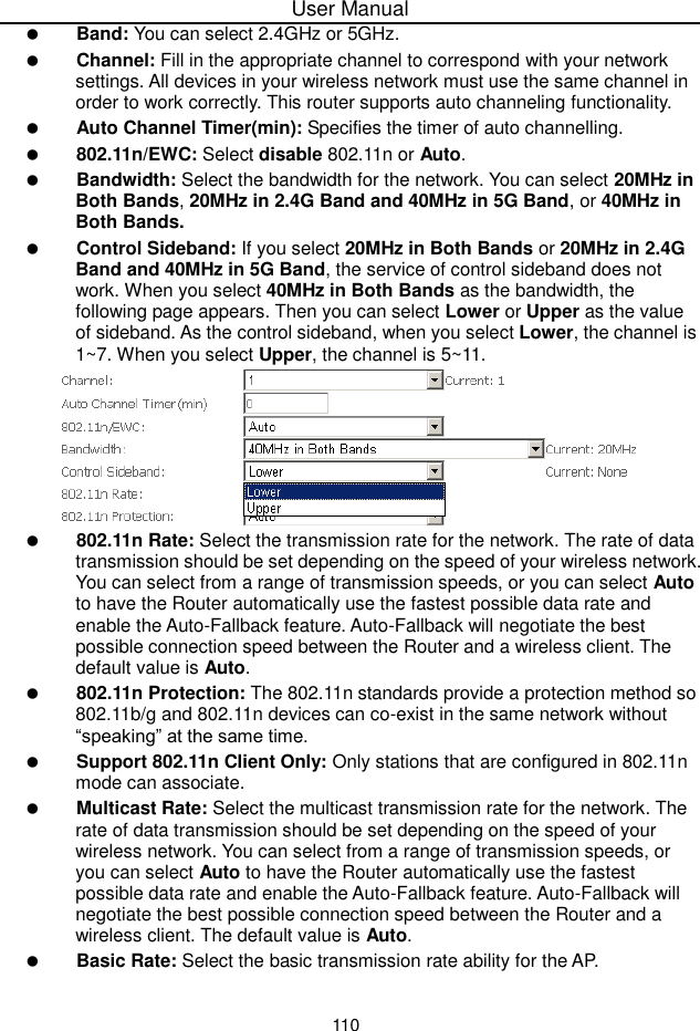
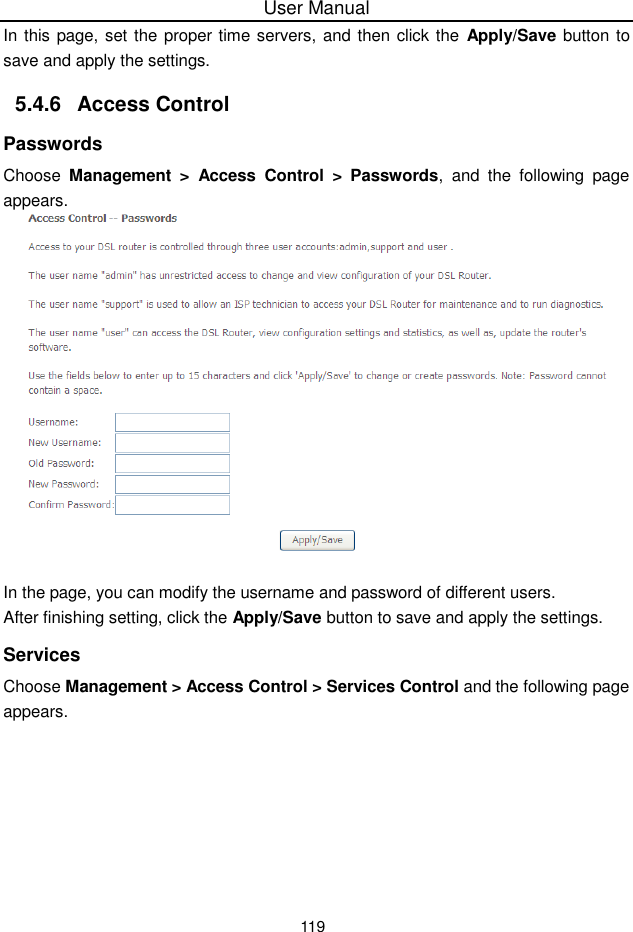
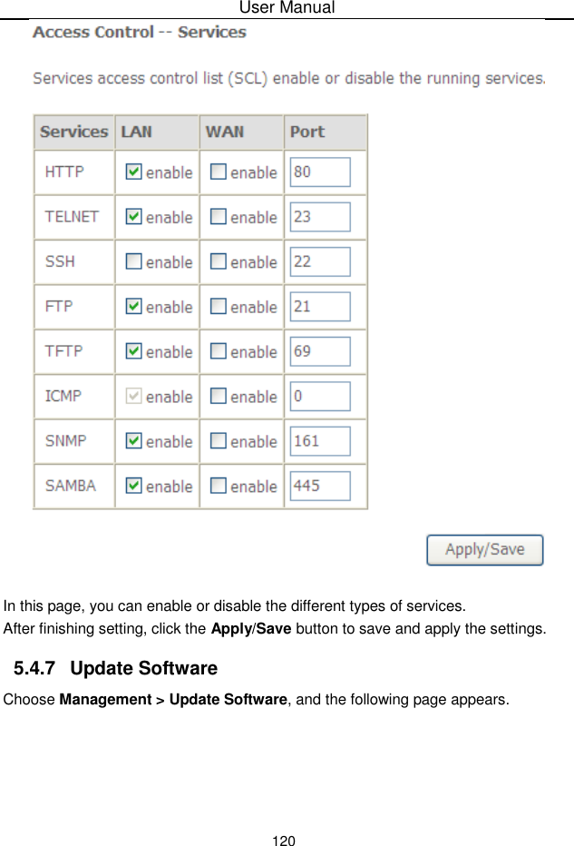
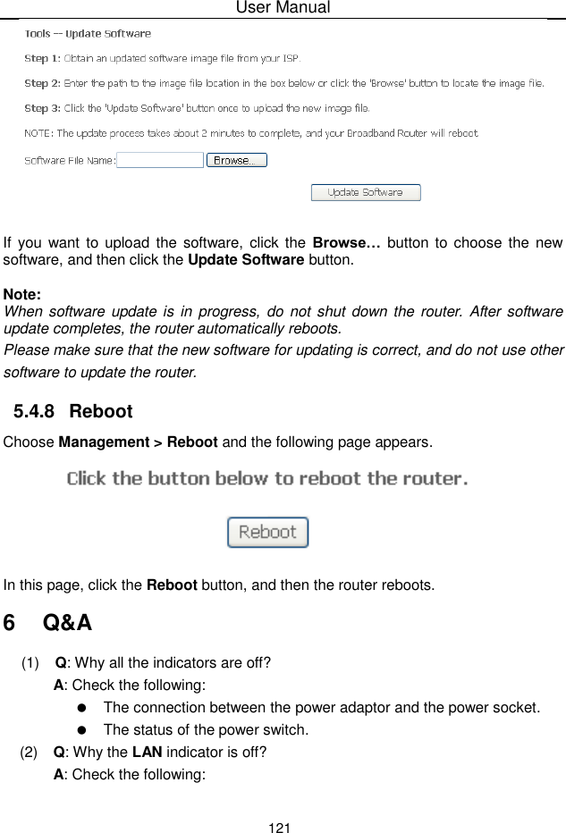
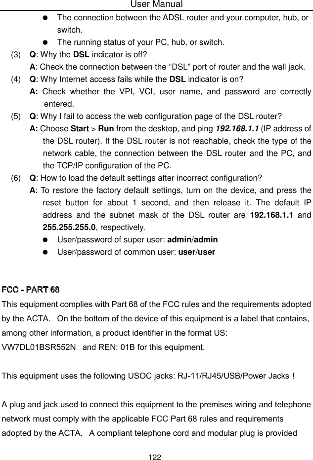
User Manual
Discussion / Help
Navigation