ADTRAN SR808A 802.11ac DOCSIS 3.0 Gateway User Manual
SmartRG, Inc. 802.11ac DOCSIS 3.0 Gateway
UserManual.wiki
>
ADTRAN
>
SR808A User Manual
User manual
Navigation menu
Upload a User Manual
Namespaces
Wiki Guide
HTML
PDF
Info
Views
User Manual
Discussion / Help
Navigation
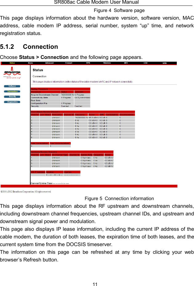
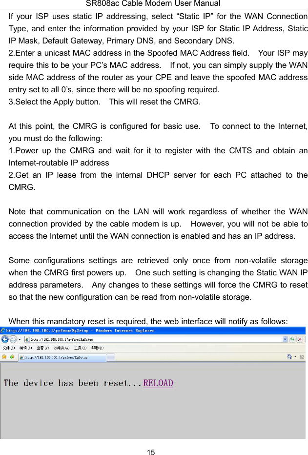
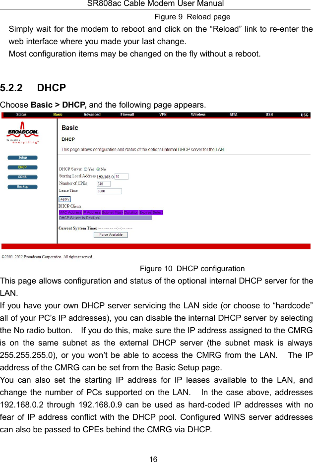
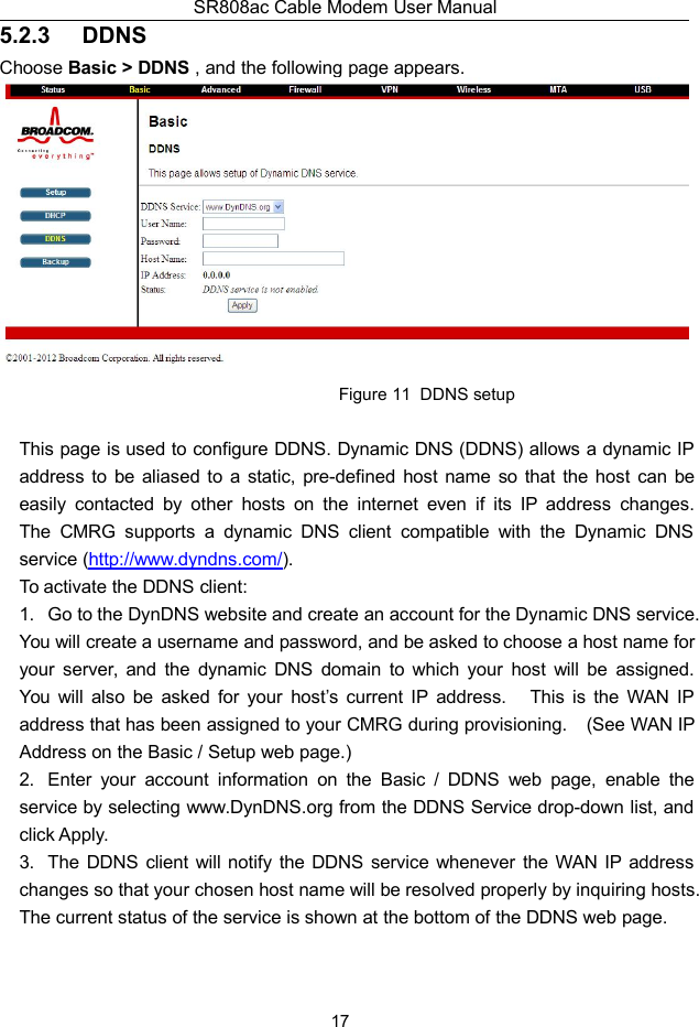
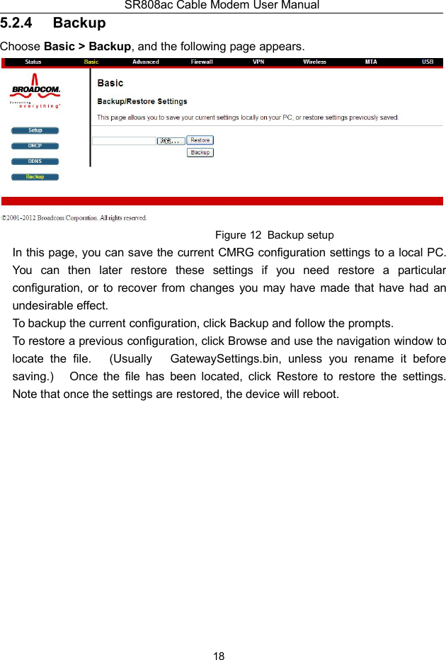
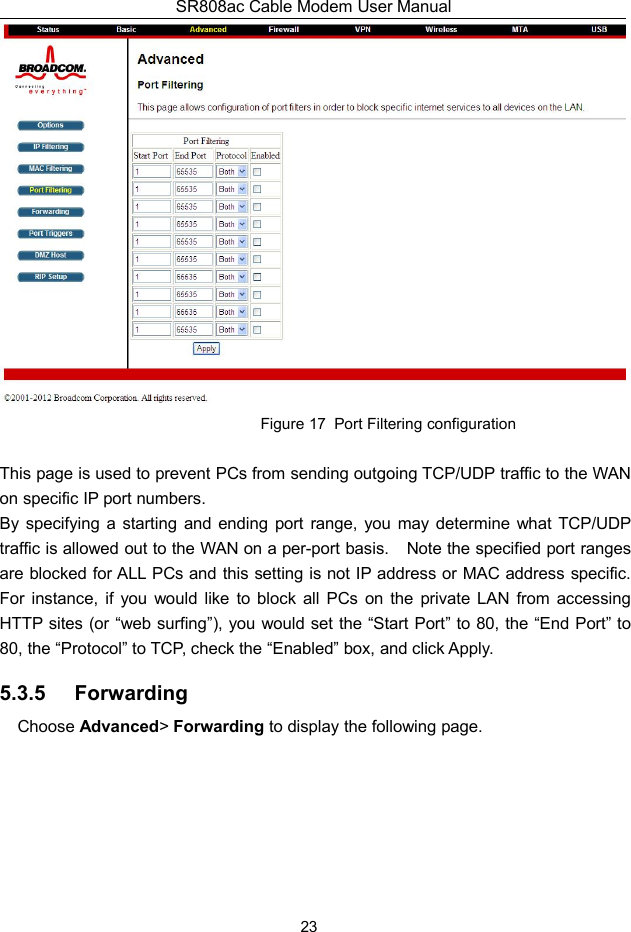
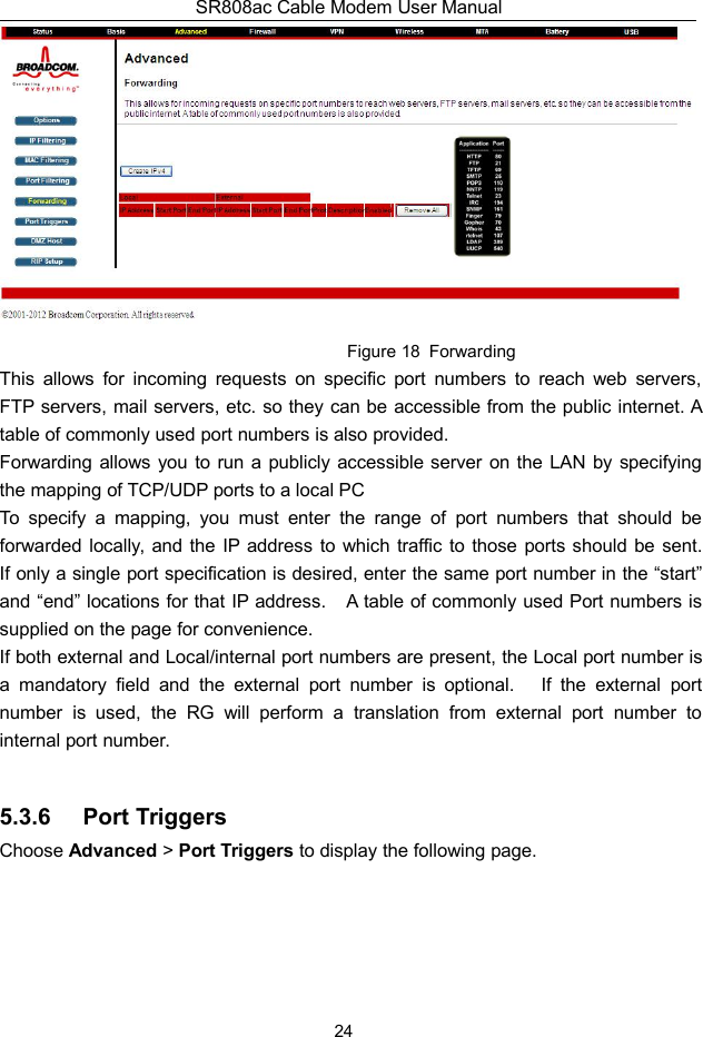
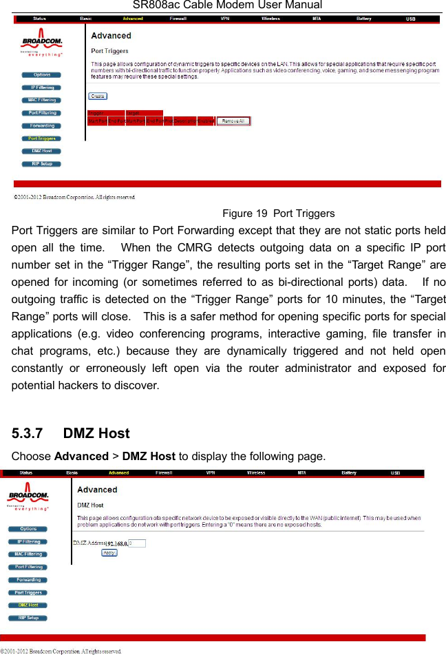
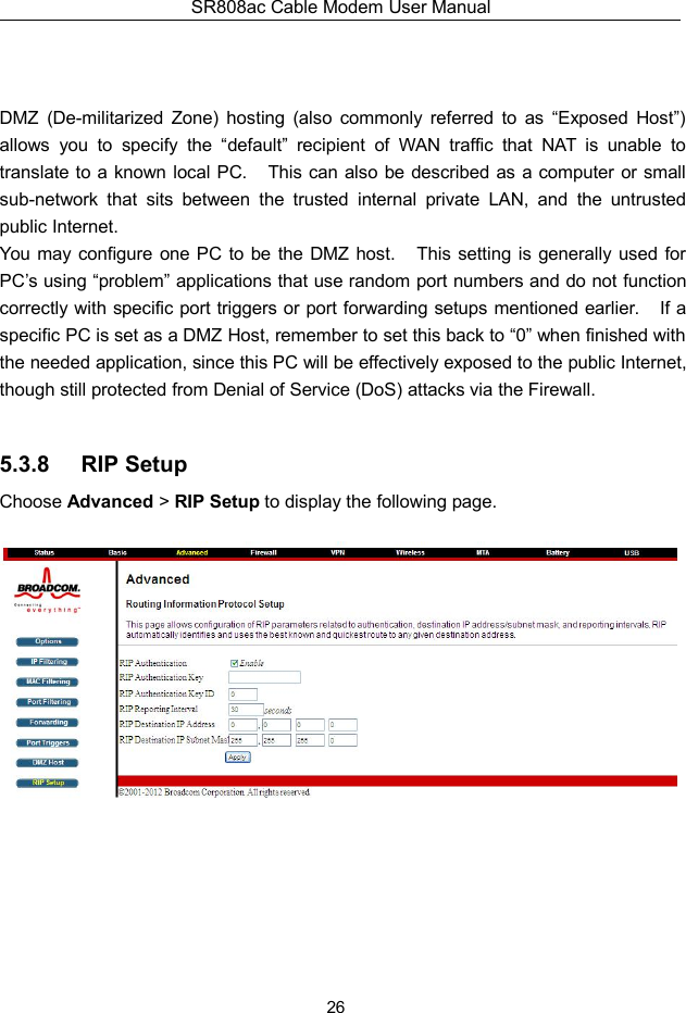
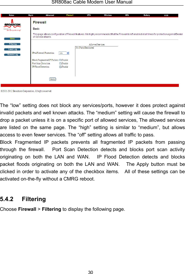
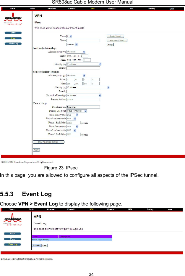
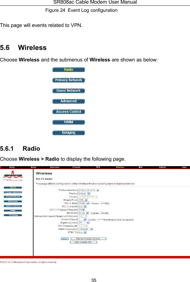
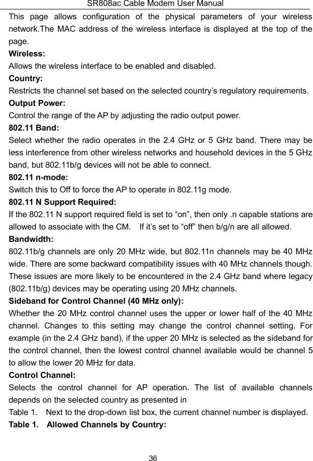
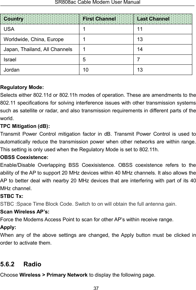
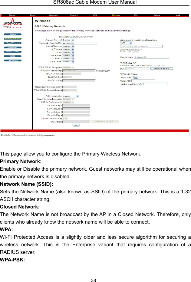
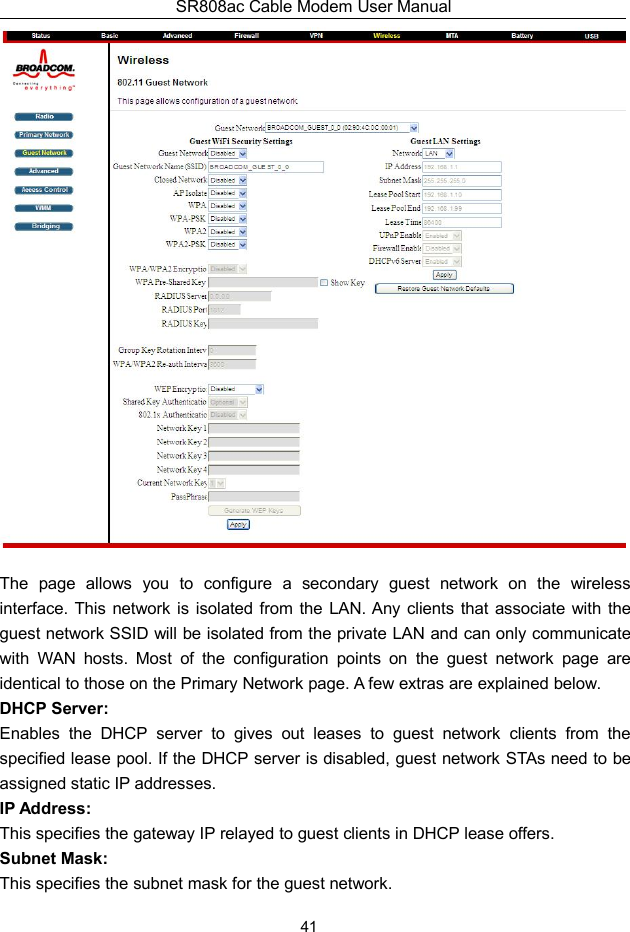
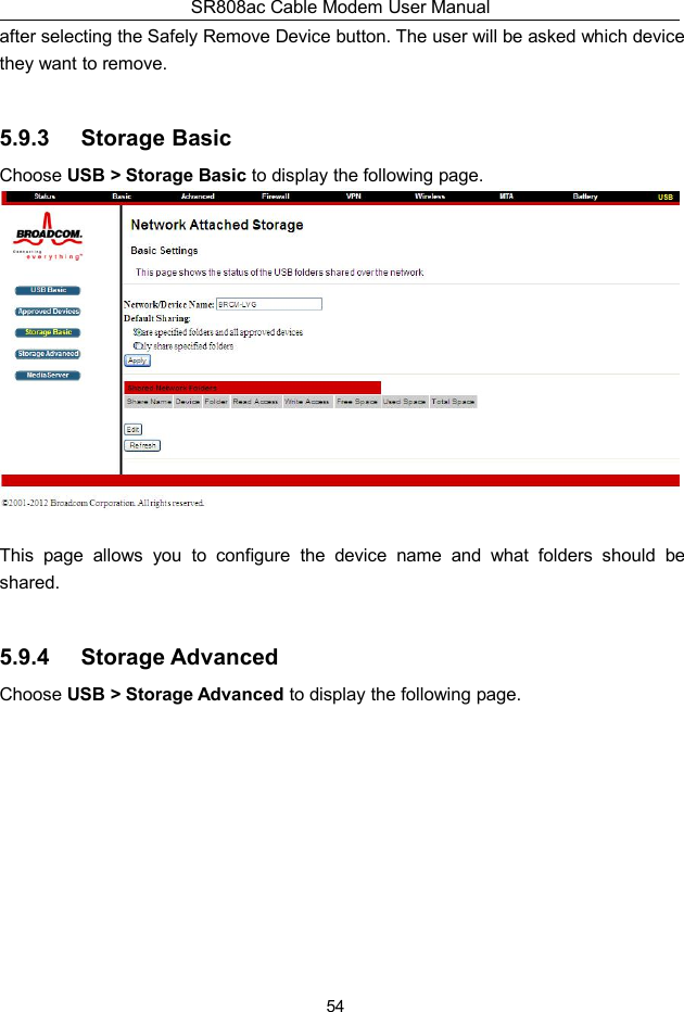
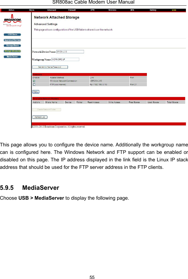
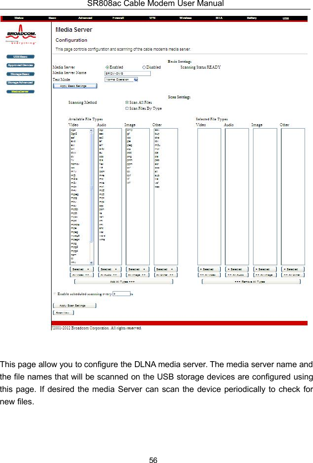
![SR808ac Cable Modem User Manual29* - candidate default, U - per-user static route, o - ODRP - periodic downloaded static routeGateway of last resort is 10.24.95.17 to network 0.0.0.010.0.0.0/8 is variably subnetted, 3 subnets, 2 masksC 10.24.80.0/24 is directly connected, Cable2/0C 10.24.81.0/24 is directly connected, Cable2/0C 10.24.95.16/28 is directly connected, FastEthernet0/0S* 0.0.0.0/0 [1/0] via 10.24.95.17In the example above, the CMRG was set up to send RIPv2 messages to the CMTS.The CMTS was also set up to receive these messages.5.4 FirewallChoose Firewall and the submenus of Firewall are shown as below:Figure 20 submenus of Firewall5.4.1 BasicChoose Firewall >Basic to display the following page.This page is used to block or exclusively allow different types of data through theCMRG from the WAN to the LAN.](https://usermanual.wiki/ADTRAN/SR808A/User-Guide-3571678-Page-33.png)