ADTRAN TRC3202 Tracer 3202 5.8 GHz Mastmount RFC User Manual 61280012L1 1A
Adtran Tracer 3202 5.8 GHz Mastmount RFC 61280012L1 1A
ADTRAN >
Users manual

TRACER 2210/3202
System Manual
1280012L1 TRACER 2210/3202 System
61280012L1-1A
February 2002

TRACER 2210/3202 System Manual © 2002 ADTRAN, Inc.
Trademarks
Any brand names and product names included in this manual are trademarks, registered trademarks, or
trade names of their respective holders.
To the Holder of the Manual
The contents of this manual are current as of the date of publication. ADTRAN reserves the right to change
the contents without prior notice.
In no event will ADTRAN be liable for any special, incidental, or consequential damages or for
commercial losses even if ADTRAN has been advised thereof as a result of issue of this publication.
901 Explorer Boulevard
P.O. Box 140000
Huntsville, AL 35814-4000
Phone: (256) 963-8000
©2002 ADTRAN, Inc.
All Rights Reserved.
Printed in U.S.A.

© 2002 ADTRAN, Inc. TRACER 2210/3202 System Manual
About this Manual
This manual provides a complete description of the TRACER 2210/3202 system and system software.
The purpose of this manual is to provide the technician, system administrator, and manager with
general and specific information related to the planning, installation, operation, and maintenance of the
TRACER 2210/3202. This manual is arranged so that needed information can be quickly and easily found.
The following is an overview of the contents.
Section 1 System Description
Provides managers with an overview of the TRACER 2210/3202 system.
Section 2 Microwave Path Engineering Basics
Explains the basics of analyzing a wireless microwave link, or path. The significant
parameters are defined, and several recommendations are offered.
Section 3 Engineering Guidelines
Provides information to assist network designers with incorporating the
TRACER 2210/3202 system into their networks.
Section 4 Network Turnup Procedure
Provides step-by-step instructions on how to install the TRACER 2210/3202 unit,
determine the parameters for the system, install the network and option modules, and
power up the system.
Section 5 User Interface Guide
Explains the terminal interface and provides a description for each of the menus available
for the TRACER 2210/3202 system.
Section 6 Trouble Shooting Guide
Provides helpful information for troubleshooting common configuration problems for the
TRACER 2210/3202 system.
Section 7 Menu Trees
Provides a detailed listing of all available menus for the TRACER 2210/3202 system.
Revision History
This is the 1st issue of this manual.
TRACER 2210/3202 System Manual © 2002 ADTRAN, Inc.
Safety Instructions
When using your telephone equipment, please follow these basic safety precautions to reduce the risk of
fire, electrical shock, or personal injury:
1. Do not use this product near water, such as a bathtub, wash bowl, kitchen sink, laundry tub, in a
wet basement, or near a swimming pool.
2. Avoid using a telephone (other than a cordless-type) during an electrical storm. There is a remote
risk of shock from lightning.
3. Do not use the telephone to report a gas leak in the vicinity of the leak.
4. Use only the power cord, power supply, and/or batteries indicated in the manual. Do not dispose of
batteries in a fire. They may explode. Check with local codes for special disposal instructions.
Save These Important Safety Instructions
Notes provide additional useful information.
Cautions signify information that could prevent service interruption.
Warnings provide information that could prevent damage to the equipment or
endangerment to human life.
© 2002 ADTRAN, Inc. TRACER 2210/3202 System Manual
Federal Communications Commission Radio Frequency Interference Statement
This equipment has been tested and found to comply with the limits for a Class A digital device, pursuant
to Part 15 of the FCC Rules. These limits are designed to provide reasonable protection against harmful
interference when the equipment is operated in a commercial environment. This equipment generates,
uses, and can radiate radio frequency energy and, if not installed and used in accordance with the
instruction manual, may cause harmful interference to radio frequencies. Operation of this equipment in a
residential area is likely to cause harmful interference in which case the user will be required to correct the
interference at his own expense.
Shielded cables must be used with this unit to ensure compliance with Class A FCC limits.
Changes or modifications to this unit not expressly approved by the party
responsible for compliance could void the user’s authority to operate the equipment.

TRACER 2210/3202 System Manual © 2002 ADTRAN, Inc.
Warranty and Customer Service
ADTRAN will replace or repair this product within five years from the date of shipment if it does not meet
its published specifications or fails while in service. For detailed warranty, repair, and return information
refer to the ADTRAN Equipment Warranty and Repair and Return Policy Procedure.
Return Material Authorization (RMA) is required prior to returning equipment to ADTRAN.
For service, RMA requests, or further information, contact one of the numbers listed at the end of this
section.
LIMITED PRODUCT WARRANTY
ADTRAN warrants that for five (5) years from the date of shipment to Customer, all products
manufactured by ADTRAN will be free from defects in materials and workmanship. ADTRAN also
warrants that products will conform to the applicable specifications and drawings for such products, as
contained in the Product Manual or in ADTRAN's internal specifications and drawings for such products
(which may or may not be reflected in the Product Manual). This warranty only applies if Customer gives
ADTRAN written notice of defects during the warranty period. Upon such notice, ADTRAN will, at its
option, either repair or replace the defective item. If ADTRAN is unable, in a reasonable time, to repair or
replace any equipment to a condition as warranted, Customer is entitled to a full refund of the purchase
price upon return of the equipment to ADTRAN. This warranty applies only to the original purchaser and
is not transferable without ADTRAN's express written permission. This warranty becomes null and void if
Customer modifies or alters the equipment in any way, other than as specifically authorized by ADTRAN.
EXCEPT FOR THE LIMITED WARRANTY DESCRIBED ABOVE, THE FOREGOING
CONSTITUTES THE SOLE AND EXCLUSIVE REMEDY OF THE CUSTOMER AND THE
EXCLUSIVE LIABILITY OF ADTRAN AND IS IN LIEU OF ANY AND ALL OTHER WARRANTIES
(EXPRESSED OR IMPLIED). ADTRAN SPECIFICALLY DISCLAIMS ALL OTHER WARRANTIES,
INCLUDING (WITHOUT LIMITATION), ALL WARRANTIES OF MERCHANTABILITY AND
FITNESS FOR A PARTICULAR PURPOSE. SOME STATES DO NOT ALLOW THE EXCLUSION
OF IMPLIED WARRANTIES, SO THIS EXCLUSION MAY NOT APPLY TO CUSTOMER.
In no event will ADTRAN or its suppliers be liable to Customer for any incidental, special, punitive,
exemplary or consequential damages experienced by either Customer or a third party (including, but not
limited to, loss of data or information, loss of profits, or loss of use). ADTRAN is not liable for damages
for any cause whatsoever (whether based in contract, tort, or otherwise) in excess of the amount paid for
the item. Some states do not allow the limitation or exclusion of liability for incidental or consequential
damages, so the above limitation or exclusion may not apply to Customer.

© 2002 ADTRAN, Inc. TRACER 2210/3202 System Manual
Customer Service, Product Support Information, and Training
ADTRAN will replace or repair this product within five years from the date of shipment if the product does
not meet its published specification, or if it fails while in service.
A return material authorization (RMA) is required prior to returning equipment to ADTRAN. For service,
RMA requests, training, or more information, see the toll-free contact numbers given below.
Presales Inquiries and Applications Support
Please contact your local distributor, ADTRAN Applications Engineering, or ADTRAN Sales:
Post-Sale Support
Please contact your local distributor first. If your local distributor cannot help, please contact ADTRAN
Technical Support and have the unit serial number available.
The Custom Extended Services (ACES) program offers multiple types and levels of service plans which
allow you to choose the kind of assistance you need. For questions, call the ACES Help Desk.
Repair and Return
If ADTRAN Technical Support determines that a repair is needed, Technical Support will coordinate with
the Custom and Product Service (CAPS) department to issue an RMA number. For information regarding
equipment currently in house or possible fees associated with repair, contact CAPS directly at the
following number:
Identify the RMA number clearly on the package (below address), and return to the following address:
ADTRAN Customer and Product Service
901 Explorer Blvd.
Huntsville, Alabama 35806
RMA # _____________
Applications Engineering (800) 615-1176
Sales (800) 827-0807
Technical Support (888) 4ADTRAN
ACES Help Desk (888) 874-2237
CAPS Department (256) 963-8722

TRACER 2210/3202 System Manual © 2002 ADTRAN, Inc.
Training
The Enterprise Network (EN) Technical Training offers training on our most popular products. These
courses include overviews on product features and functions while covering applications of ADTRAN's
product lines. ADTRAN provides a variety of training options, including customized training and courses
taught at our facilities or at your site. For more information about training, please contact your Territory
Manager or the Enterprise Training Coordinator.
Radio Frequency Interface Statement
This equipment has been tested and found to comply with the limits for an intentional radiator, pursuant to
Part 15, Subpart C of the FCC Rules. This equipment generates, uses, and can radiate radio frequency
energy. If not installed and used in accordance with the instructions, it may cause interference to radio
communications.
The limits are designed to provide reasonable protection against such interference in a residential situation.
However, there is no guarantee that interference will not occur in a particular installation. If this equipment
does cause interference to radio or television reception, which can be determined by turning the equipment
on and off, the user is encouraged to try to correct the interference by one or more of the following
measures:
• Reorient or relocate the receiving antenna of the affected radio or television.
• Increase the separation between the equipment and the affected receiver.
• Connect the equipment and the affected receiver to power outlets on separate circuits.
• Consult the dealer or an experienced radio/TV technician for help.
Training Phone (800) 615-1176, ext. 7500
Training Fax (256) 963-6700
Training Email training@adtran.com
Changes or modifications not expressly approved by ADTRAN could void the user’s
authority to operate the equipment.

© 2002 ADTRAN, Inc. TRACER 2210/3202 System Manual
FCC Output Power Restrictions
The FCC does not require licensing to implement this device. However, the FCC has established
restrictions regarding maximum output power and the adjustments required when employing directional
gain antennas. (Refer to “Setting the Transmitter Power” in Section 2 of this manual). These restrictions
are detailed in FCC Part 15.247 (b)(1), (b)(3)(i), and (3)(iii). It is the responsibility of the individuals
designing and implementing the radio system to assure compliance with these and any other pertinent FCC
Rules and Regulations. This device must be professionally installed.
Exposure to Radio Frequency Fields
The TRACER 2210/3202 is designed to operate at 5.8 GHz with 100 mW maximum transmit power.
This level of RF energy is below the Maximum Permissible Exposure (MPE) levels specified in FCC OET
65:97-01. The installation of high gain antenna equipment in the system configuration may create the
opportunity for exposure to levels higher than recommended for the general population at a distance less
than 15 feet (4.6 meter) from the center of the antenna. The following precautions must be taken during
installation of this equipment:
• The installed antenna must not be located in a manner that allows exposure of the general population to
the direct beam path of the antenna at a distance less than 15 feet (4.6 meters). Installation on towers,
masts, or rooftops not accessible to the general population is recommended; or
• Mount the antenna in a manner that prevents any personnel from entering the area within 15 feet (4.6
meter) from the front of the antenna.
• It is recommended that the installer place radio frequency hazard warnings signs on the barrier that
prevents access to the antenna.
• Prior to installing the antenna to the RIU output, make sure the power is adjusted to the settings specified
in section 2 of this manual.
• During antenna installation, be sure that power to the TRACER equipment is turned off in order to
prevent any energy presence on the coaxial connector.
• During installation and alignment of the antenna, do not stand in front of the antenna assembly.
• During installation and alignment of the antenna, do not handle or touch the front of the antenna.
These simple precautions must be taken to prevent general population and installation personnel from
exposure to RF energy in excess of specified MPE levels.

TRACER 2210/3202 System Manual © 2002 ADTRAN, Inc.

61280012L1-1A © 2001 ADTRAN, Inc. Page 11 of 14
SYSTEM DESCRIPTION
This section of ADTRAN’s TRACER 2210/3202 System Manual is designed for use by network engi-
neers, planners, and designers for overview information about the TRACER 2210/3202.
It contains general information and describes physical and operational concepts, network relationships,
provisioning, testing, alarm status, and system monitoring. This section should be used in conjunction with
Section 2, Engineering Guidelines, of the system manual.
CONTENTS
System Overview . . . . . . . . . . . . . . . . . . . . . . . . . . . . . . . . . . . . . . . . . . . . . . . . . . . . . . . . . . . . . . . 16
Features and Benefits . . . . . . . . . . . . . . . . . . . . . . . . . . . . . . . . . . . . . . . . . . . . . . . . . . . . . . . . . . . 16
Configuration and Management . . . . . . . . . . . . . . . . . . . . . . . . . . . . . . . . . . . . . . . . . . . . . . . . . 16
Data Interface Unit . . . . . . . . . . . . . . . . . . . . . . . . . . . . . . . . . . . . . . . . . . . . . . . . . . . . . . . . . . . 16
Radio Interface Unit . . . . . . . . . . . . . . . . . . . . . . . . . . . . . . . . . . . . . . . . . . . . . . . . . . . . . . . . . . 16

Section 1, System Description TRACER 2210/3202 System Manual
Page 12 of 14 © 2001 ADTRAN, Inc. 61280012L1-1A
1. SYSTEM OVERVIEW
The ADTRAN TRACER® 2210/3202 wireless data system provides low-cost point-to-point connectivity
between the end user’s Data Terminal Equipment (DTE) for applications such as LAN to LAN bridging
and Videoconferencing. TRACER 2210/3202 is capable of achieving distances up to 30 miles. As autho-
rized under Part 15.247 of the FCC Rules, the TRACER 2210/3202 operates license-free in the 5.725 to
5.850 GHz industrial, scientific and medical (ISM) band.
The TRACER 2210/3202 system is composed of two primary hardware elements: The 2210 Data Interface
Unit (DIU) and The 3202 Radio Interface Unit (RIU). The 2210 DIU is contained in a compact plastic
housing and supports synchronous data rates from 56 kbps to 1.536 Mbps in 56 or 64 kbps increments. A
single V.35 physical interface provides a connection to the end user’s DTE equipment. The weatherproof
RIU may be mast mounted up to 700 ft. from the DIU using 24 AWG twisted pair wires. All signaling and
power functions between the DIU and RIU are provided over this simple four-wire connection. The
TRACER 2210/3202 design locates the radio at the antenna to maximize signal efficiency, while eliminat-
ing the requirement of expensive coax to link the DIU and RIU.
For configuration and testing, the TRACER 2210/3202 provides the capability to control the remote
TRACER 2210/3202 through a separate maintenance channel. The TRACER 2210/3202 has several
built-in test capabilities including remote loopback and 511 BERT test patterns. Complete configuration
and performance data is available from the front panel keypad and from the two-line by 16-character LCD
display on the 2210 data interface. For additional configuration and monitoring options, the TRACER
2210/3202 supports a VT-100 terminal configuration and control mode, which is available through the
control port.
2. FEATURES AND BENEFITS
The following is a brief list of TRACER 2210/3202 features and benefits:
Configuration and Management
• Easy to use front-panel keypad for configuration and monitoring
• Remote configuration
Data Interface Unit
• Tabletop or wall-mounted housing
• Single V.35 DTE interface
• Nx56 or Nx64 operation for data rates to 1.536 Mbps
• Local and remote loopback capability
Radio Interface Unit
• Digital microwave radio
• No license required per FCC Rules Part 15.247
• Direct-sequence spread spectrum
• Frequency: 5.725 to 5.850 GHz

TRACER 2210/3202 System Manual Section 1, System Description
61280012L1-1A © 2001 ADTRAN, Inc. Page 13 of 14
• Point-to-point, up to 30 miles
• Mast mounted RIU for maximum signal efficiency
• 700 feet of 22AWG or 600 feet of 24 AWG wire between DIU and RIU

Section 1, System Description TRACER 2210/3202 System Manual
Page 14 of 14 © 2001 ADTRAN, Inc. 61280012L1-1A

61280012L1-1A © 2002 ADTRAN, Inc. 15
MICROWAVE PATH ENGINEERING BASICS
CONTENTS
Line-of-site . . . . . . . . . . . . . . . . . . . . . . . . . . . . . . . . . . . . . . . . . . . . . . . . . . . . . . . . . . . . . . . . . . . . 16
Decibels . . . . . . . . . . . . . . . . . . . . . . . . . . . . . . . . . . . . . . . . . . . . . . . . . . . . . . . . . . . . . . . . . . . . . . . 16
Receiver Power . . . . . . . . . . . . . . . . . . . . . . . . . . . . . . . . . . . . . . . . . . . . . . . . . . . . . . . . . . . . . . . . . 17
Path Loss . . . . . . . . . . . . . . . . . . . . . . . . . . . . . . . . . . . . . . . . . . . . . . . . . . . . . . . . . . . . . . . . . . . . . 18
Antenna Alignment . . . . . . . . . . . . . . . . . . . . . . . . . . . . . . . . . . . . . . . . . . . . . . . . . . . . . . . . . . . . . . 19
Antenna Beam Patterns . . . . . . . . . . . . . . . . . . . . . . . . . . . . . . . . . . . . . . . . . . . . . . . . . . . . . . . 20
Fresnel Zones, Earth Curvature, & Antenna Heights . . . . . . . . . . . . . . . . . . . . . . . . . . . . . . . . . 21
Coaxial Cable . . . . . . . . . . . . . . . . . . . . . . . . . . . . . . . . . . . . . . . . . . . . . . . . . . . . . . . . . . . . . . . . . . 22
Receiver Sensitivity . . . . . . . . . . . . . . . . . . . . . . . . . . . . . . . . . . . . . . . . . . . . . . . . . . . . . . . . . . . . . 22
Fade Margin . . . . . . . . . . . . . . . . . . . . . . . . . . . . . . . . . . . . . . . . . . . . . . . . . . . . . . . . . . . . . . . . . . . 22
Path Availability . . . . . . . . . . . . . . . . . . . . . . . . . . . . . . . . . . . . . . . . . . . . . . . . . . . . . . . . . . . . . . . . 23
ADTRAN Link Analyzer . . . . . . . . . . . . . . . . . . . . . . . . . . . . . . . . . . . . . . . . . . . . . . . . . . . . . . . . . . 24
FIGURES
Figure 1. Example Microwave Path with Parameters . . . . . . . . . . . . . . . . . . . . . . . . . . . . . . . . . . 19
Figure 2. Typical Antenna Beam Pattern . . . . . . . . . . . . . . . . . . . . . . . . . . . . . . . . . . . . . . . . . . . 20

Section 2, Microwave Path Engineering Basics TRACER 2210/3202 System Manual
16 © 2002 ADTRAN, Inc. 61280012L1-1A
1. LINE-OF-SITE
The TRACER 2210/3202 system is designed for operation in the 5725 MHz to 5850 MHz unlicensed
Industrial, Scientific, and Medical (ISM) frequency band, which is near the middle of what is traditionally
referred to as the C-band portion of X-band. Radio wave propagation in this band exhibits microwave
characteristics, which are ideally suited for point-to-point, line-of-sight communications. Line-of-sight
essentially requires that the transmitting antenna and receiving antenna are able to “see” each other, and
that the straight-line path between the two antennas is free of any obstructions, such as buildings, trees,
mountains, and, in longer paths, even the curvature of the earth.
2. DECIBELS
The received signal power equation is often expressed in a decibel (dB) format, which turns the power
multiplication and division operations into addition and subtraction operations. In general, any quantity
can be expressed in decibels. If the quantity (x) is a power level, the decibel equivalent is defined as
If the quantity x is referenced to a milliwatt (mW), then the decibel-milliwatt (dBm) is used instead of a
generic decibel.
Point-to-Point Wireless communication from a single site to another
individual site. Contrast with point-to-multipoint
Line-of-Sight An unobstructed, direct path exists between the
transmitting and the receiving antennas.
xdB 10 log10 x()⋅=(dB)
xdBm 10 log10
x
1mW
-------------
⋅=(dBm)

TRACER 2210/3202 System Manual Section 2, Microwave Path Engineering Basics
61280012L1-1A © 2002 ADTRAN, Inc. 17
3. RECEIVER POWER
The radio frequency (RF) signal power that is available at the input to the receiving TRACER 2210/3202
system is the next parameter of interest in analyzing a wireless path. Per FCC 15.247 rules, the TRACER
3202 RIU is allowed to output a maximum power level of 100 mW, which is equivalent to 20 dBm. This
output signal will be attenuated and distorted by various factors, all of which will degrade the original
signal and affect the signal strength and quality as sensed by the receiving unit. A simplified power budget
analysis is beneficial to perform after verifying a suitable line-of-sight path to determine if the microwave
path is suitable, even for ideal, non-distorted signals.
The equation relating received signal power to the other microwave parameters is
where the variables in the equation are defined as
PRreceived power (Watts)
PTtransmitted power (100 mW for TRACER 2210/3202)
GTtransmit antenna gain
GRreceive antenna gain
λcarrier wavelength ( c / ƒ ) (meters)
dpath distance (meters)
Lother losses (RF coaxial cable, etc.)
As previously mentioned, the transmitted power is limited for the 5.8 GHz ISM band to a maximum of
20 dBm. The actual transmit and receive antenna gain values are strictly dependent upon the physical
characteristics of the antennas installed for each link. Typical gains are between 20 and 30 dB. For
example, a 4 foot diameter, flat panel C-band antenna from a popular antenna manufacturer advertises a
gain of 23.5 dB. The carrier wavelength is the physical wavelength of the main RF carrier being used for
communication, and is usually approximated at the center frequency of the band, which is 5787.5 MHz.
This gives a wavelength of 5.18 cm.
The path distance is simply the physical distance between the transmit and receive antennas. For the
TRACER 2210/3202 these distances can range up to 30 miles. The final parameter L incorporates all other
signal power losses in the microwave link, most of which are caused by antenna feed, or coaxial cables
used to connect the TRACER 3202 N-type connector to the antenna connector. Since the TRACER 3202
is a mast-mounted device, the antenna feed losses are minimized by requiring only short runs of coaxial
cable.
PR
PTGTGRλ2
4π()
2d2L
---------------------------=(watts, W)

Section 2, Microwave Path Engineering Basics TRACER 2210/3202 System Manual
18 © 2002 ADTRAN, Inc. 61280012L1-1A
4. PATH LOSS
The expression
where
fcarrier frequency (Hz)
λcarrier wavelength ( c / f ) (meters)
dpath distance (meters)
cspeed of light, free-space (meters)
is called the path loss, and increases rapidly as either path length increases or carrier wavelength decreases
(which happens as the carrier frequency increases). So, longer microwave paths will naturally experience
more path loss than shorter paths. Likewise, higher frequency microwave communication will experience
more path loss than lower frequency microwave communication.
Table 1 tabulates path loss values for various path lengths for the TRACER 2210/3202 system. Values not
listed in the table can be interpolated from those listed.
Table 1. Path Loss for Given Path Lengths
Path Length
(miles)
Path Loss
(dB)
1112
2118
3121
4124
5126
10 132
15 135
20 138
25 140
30 141
35 143
LP
4πd
λ
----------
24πdf
c
------------
2
== (watts, W)
TRACER 2210/3202 System Manual Section 2, Microwave Path Engineering Basics
61280012L1-1A © 2002 ADTRAN, Inc. 19
When using decibel notation, the received power equation becomes
or
Where, in the second equation the path loss has been lumped into a single quantity, LP
, as discussed
previously. When using decibel notation, it is necessary that all quantities are individually converted to
decibels prior to performing addition and subtraction.
When d is expressed in miles and f in GHz, the path loss expression in decibels becomes
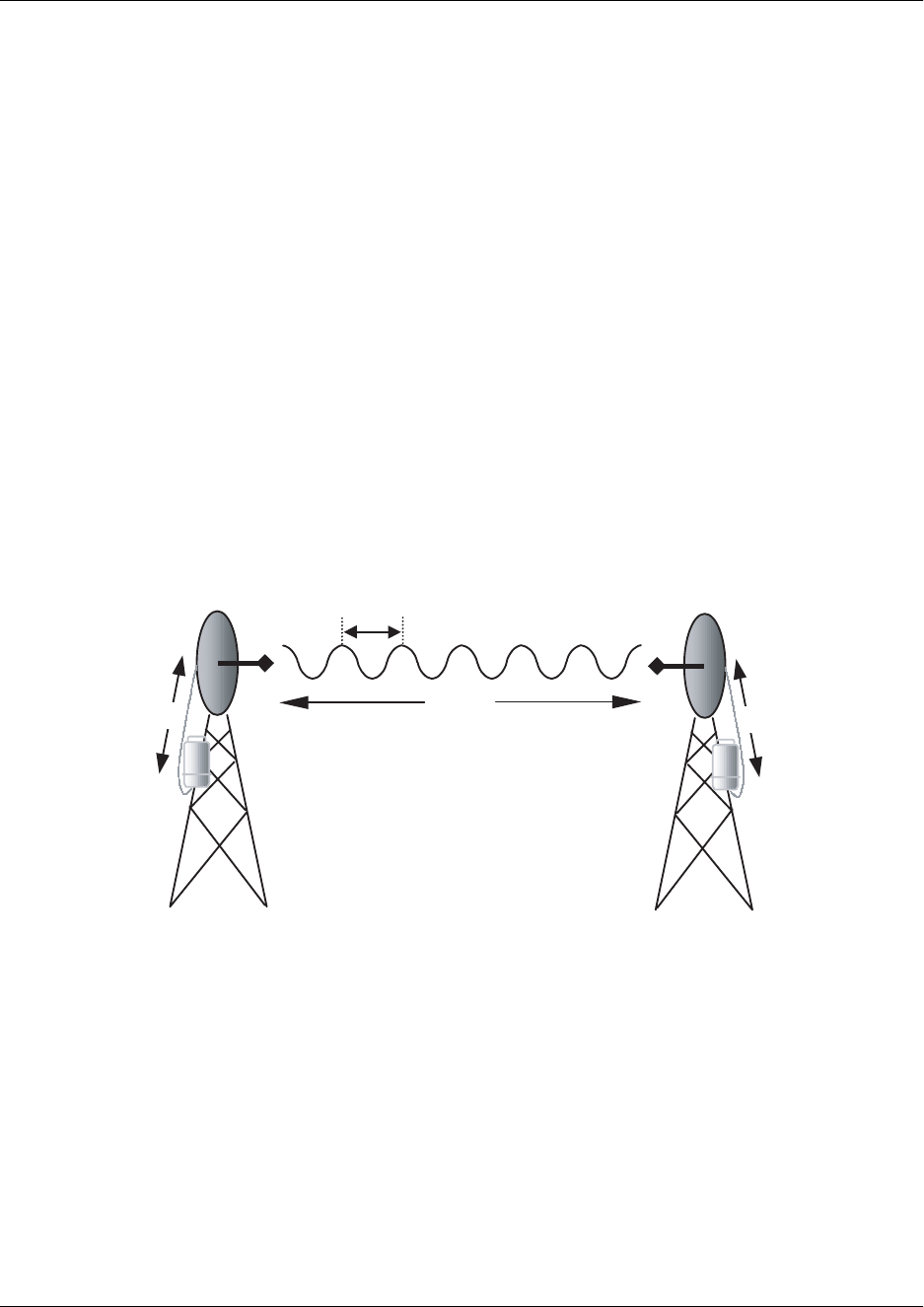
Figure 1 illustrates a wireless link containing all of the parameters previously discussed.
Figure 1. Example Microwave Path with Parameters
5. ANTENNA ALIGNMENT
With line-of-sight microwave communications, optimum system performance requires that the
transmitting and receiving antennas are properly aligned. This will ensure maximum received signal
power at each receiver. Antenna alignment must be achieved in both azimuth (along a horizontal plane)
and elevation (along a vertical plane). A received signal strength indicator (RSSI) is used to aid the
equipment installer in determining when alignment is maximized, by simply ensuring maximum RSSI.
The RSSI indicator for the TRACER 2210/3202 system is provided on the LCD display of the 2210 unit,
and is presented as a series of asterisks. More asterisks means more RSSI, which ensures more received
signal strength and better link performance.
PRPTGTGRL–20 · log10
–++ 4πdf
c
------------
2
==
(dB)
LPPTGTGRL–LP
–++=(dB)
LP96.6 20 log10 d() 20·log+10 f()⋅+= (dB)
GTGR
d, LP
P
TPR
λ
L
L
Section 2, Microwave Path Engineering Basics TRACER 2210/3202 System Manual
20 © 2002 ADTRAN, Inc. 61280012L1-1A
Using the 2210 keypad, look at the menu option
STATUS ⇒ RADIO STATUS ⇒ RSSI
to examine the RSSI value of the local TRACER 2210/3202 system.
If the remote system has acquired a useful signal from the remote system, then the remote TRACER
2210/3202 RSSI can also be viewed from the local 2210 unit menu, via the keypad menu sequence:
STATUS ⇒ FAR RADIO STATUS ⇒ RSSI
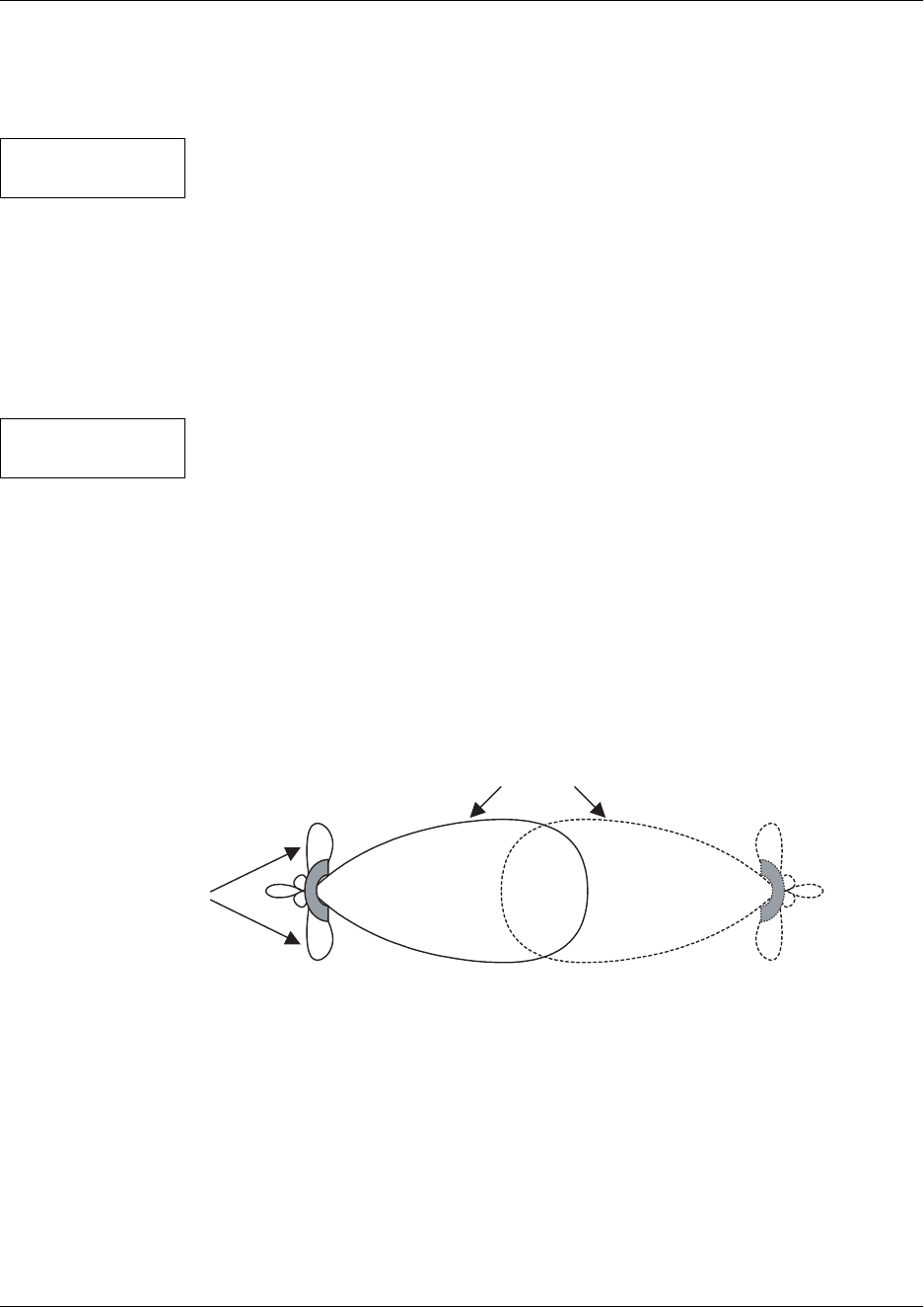
Antenna Beam Patterns
Directly related to the subject of antenna alignment is the topic of antenna beam patterns. Antennas being
used with the TRACER 2210/3202 system will have a particular beam shape determined in part by the
physical construction and geometry of the antenna. The antenna beam patterns are characterized by a
dominant main lobe, which is the preferred lobe to use for point-to-point communications, and several side
lobes, as shown in Figure 2. The antenna alignment step to setting up a microwave link is in fact steering
the main lobes of both antennas until the main lobe of one transmitter is centered on the receiving element
of the receiving antenna.
Figure 2. Typical Antenna Beam Pattern
Antennas are also designed to radiate RF energy efficiently for a specific range of frequencies. Please
consult the data sheet for your particular antenna make and model to ensure that it is specified to operate in
the 5725 MHz to 5850 MHz frequency band.
RSSI
[********* ____]
FAR RSSI
[********* ____]
main lobe
side lobes

TRACER 2210/3202 System Manual Section 2, Microwave Path Engineering Basics
61280012L1-1A © 2002 ADTRAN, Inc. 21
Fresnel Zones, Earth Curvature, & Antenna Heights
The Fresnel zones correspond to regions in the microwave path where reflections of the intended signal
occur and combine in both constructive and destructive manners with the main signal, thereby either
enhancing or reducing the net power at the receiver.
In general, the odd numbered Fresnel zones (1, 3, 5, ...) add constructively at the receiver, while the even
numbered Fresnel zones (2, 4, 6, ...) add destructively at the receiver.
The first Fresnel zone corresponds to the main lobe, and must be at least 60% free of physical obstructions for
the path calculations to be valid. Since the main lobe contains the vast majority of the microwave energy, this
zone is typically used to determine proper antenna heights when placing antennas on towers or buildings.
The curvature of the Earth becomes a legitimate obstruction for path lengths of 7 miles or greater, and must
also be accounted for when determining minimum antenna heights.
The aggregate expression for minimum antenna height that incorporates both the 60% first Fresnel zone
and the Earth curvature is given by
where f is in GHz and d is in miles.
Table 2 tabulates minimum antenna heights for given path lengths.
Table 2. Minimum Antenna Height for Given Path Lengths
Path Length
(miles)
Min. Antenna Height
(ft)
222
432
641
850
10 60
12 70
14 81
16 92
18 104
20 117
22 131
24 145
26 161
28 177
30 194
32 213
34 232
36 252
h72.1 d
4f
----- 0.125d2
+= (feet)

Section 2, Microwave Path Engineering Basics TRACER 2210/3202 System Manual
22 © 2002 ADTRAN, Inc. 61280012L1-1A
6. COAXIAL CABLE
Coaxial cable will be required to attach the TRACER 3202 mast unit to the antenna. The length of the
cable will vary from a few feet to several feet, depending upon your application and the proximity of the
TRACER 3202 to the antenna. Since the data/power cable attaching the TRACER 2210 indoor unit to the
TRACER 3202 mast unit can operate at lengths of up to 700 feet, it is recommended that this cable absorb
as much of the length between the 2210 unit and the antenna as possible. This will also decrease coaxial
cable losses in the overall power budget for the link, which was described previously.
Various grades of coaxial cable will work sufficiently well for connecting the TRACER 3202 unit to the
antenna. A low-loss coaxial cable is suggested to minimize cable losses. One end of the cable will require
an N-type male connector (plug) to mate with the TRACER 3202 unit. The other end of the coax will
require a connector compatible with the antenna chosen for the installation, which is usually also an N-type
male connector (plug). Additionally, it is recommended that both connectors on the coaxial cable be
weatherproofed from the elements to prevent corrosion and electrical shorting.
Table 3 gives typical loss figures for some of the more common coaxial cable types, per foot
In certain areas where lightning strikes are frequent, a lightning arrestor can be installed directly on the
antenna. This will help protect the RF electronics in the downstream path from damaging voltages and
currents, including the TRACER 3202 unit.
7. RECEIVER SENSITIVITY
Receiver sensitivity is a value expressed in decibels referenced to one milliwatt (dBm) that corresponds to
the minimum amount of signal power needed at the receiver to achieve a given bit error rate (BER).
Receiver sensitivity is usually a negative number of decibels, and as such smaller receiver sensitivity is
better for a given BER. Several factors affect receiver sensitivity, including the data bandwidth of the
wireless link, and the amount of additional signal degradation introduced in the receiver electronics. The
receiver sensitivity of the TRACER 3202 is -86 dBm at 10-6 BER.
8. FADE MARGIN
Fade margin is a value indicating the amount of extra signal power available to the receiver to operate at a
maximum bit error rate (BER). Higher levels of fade margin are better, and will protect the viability of the
microwave link against signal fading. Fade margin is simply the difference between the available signal
power at the receiver and the receiver sensitivity, discussed previously:
Table 3. Typical Coaxial Loss for Common Cable Types, per Foot
Cable Type Cable Loss (dB/ft)
RG-213, RG-214, RG-393 0.2
RG-142 0.3
RG-58, RG-223 0.4
RG-174, RG-316 0.7
FP
RPsens
–PRGTGRL–LP
–Psens
–++== (dB)

TRACER 2210/3202 System Manual Section 2, Microwave Path Engineering Basics
61280012L1-1A © 2002 ADTRAN, Inc. 23
9. PATH AVAILABILITY
The path availability of a wireless link is a metric that expresses the fractional amount of time a link is
available over some fixed amount of time, and depends on several factors. Path availability is expressed as
where the parameters are
aterrain factor
bclimate factor
fcarrier frequency (GHz)
dpath length (miles)
Ffade margin (dB)
The terrain factor is a quantity that compensates the link availability for different types of terrain.
Generally speaking, the more smooth an area's terrain is, the less availability a wireless link running over
that terrain will have, primarily due to multipath reflections. In contrast, secondary microwave signals will
be randomly dispersed over rough terrain, and will not interfere with the main signal lobe as badly as in the
smooth terrain case. The terrain factor values normally used are listed below:
The climate factor is a quantity that compensates the link availability for different types of climates
(weather). In general, microwave links operating in areas with high humidity will have less availability
than those in arid areas, primarily because water is a dispersive mechanism to microwave energy, and
causes the main signal lobe to refract and disperse away from the receiver location. The climate factor
values normally used are listed below.
Terrain Terrain Factor Description
Smooth 4 water, flat desert
Average 1 moderate roughness
Mountainous 1/4 very rough, mountainous
Climate Climate Factor Description
Very Dry 1/8 desert regions
Temperate 1/4 mainland, interior region
Humid 1/2 humid and coastal regions
A1 2.5 10 6–
×()abfd310 F10⁄–
()–[]100%×=(dB)

Section 2, Microwave Path Engineering Basics TRACER 2210/3202 System Manual
24 © 2002 ADTRAN, Inc. 61280012L1-1A
10. ADTRAN LINK ANALYZER
A very useful program is available on the Internet that can be used as a simple power budget calculator to
determine if a link is suitable for use with the TRACER 2210/3202 system. The program is a JAVA applet
that runs in an Internet browser window, and can be accessed at http://www.adtranwireless.com by
clicking on the Link Analyzer icon.
To accurately model system parameters with regard to the TRACER 2210/3202 system, the following Link
Analyzer options should be set as follows:
5.8 GHz Band (select this button)
RF Mounting Options Rack Mounted (both ends)
RF to Antenna Cable Type ¼ in (15.5 dB/100 ft)
RF to Antenna Cable Length (change to actual length, e.g. 10 ft)
Refer to the Link Analyzer help file for more information on how to use the program.
More comprehensive microwave path analysis software packages exist, and can be used to gain a very
detailed feasibility study for physical locations.

61280012L1-1A © 2001 ADTRAN, Inc. 25
ENGINEERING GUIDELINES
CONTENTS
Equipment Dimensions . . . . . . . . . . . . . . . . . . . . . . . . . . . . . . . . . . . . . . . . . . . . . . . . . . . . . . . . . . 26
TRACER 2210 DIU . . . . . . . . . . . . . . . . . . . . . . . . . . . . . . . . . . . . . . . . . . . . . . . . . . . . . . . . . . . 26
TRACER 3202 RFU . . . . . . . . . . . . . . . . . . . . . . . . . . . . . . . . . . . . . . . . . . . . . . . . . . . . . . . . . . 26
Power Requirements . . . . . . . . . . . . . . . . . . . . . . . . . . . . . . . . . . . . . . . . . . . . . . . . . . . . . . . . . . . . 26
Cable Requirements . . . . . . . . . . . . . . . . . . . . . . . . . . . . . . . . . . . . . . . . . . . . . . . . . . . . . . . . . . . . . 26
Reviewing the Front Panel Design . . . . . . . . . . . . . . . . . . . . . . . . . . . . . . . . . . . . . . . . . . . . . . . . . 26
Front Panel LEDs . . . . . . . . . . . . . . . . . . . . . . . . . . . . . . . . . . . . . . . . . . . . . . . . . . . . . . . . . . . . 26
Reviewing the TRACER 2210 Rear Panel Design . . . . . . . . . . . . . . . . . . . . . . . . . . . . . . . . . . . . . 28
RADIO Connector . . . . . . . . . . . . . . . . . . . . . . . . . . . . . . . . . . . . . . . . . . . . . . . . . . . . . . . . . . . . 28
RS-232 Connection. . . . . . . . . . . . . . . . . . . . . . . . . . . . . . . . . . . . . . . . . . . . . . . . . . . . . . . . . . . 29
V.35 Nx56/64 Connection . . . . . . . . . . . . . . . . . . . . . . . . . . . . . . . . . . . . . . . . . . . . . . . . . . . . . . 29
Reviewing the TRACER 3202 Design . . . . . . . . . . . . . . . . . . . . . . . . . . . . . . . . . . . . . . . . . . . . . . . 30
FIGURES
Figure 1. TRACER 2210/3202 Front Panel Layout . . . . . . . . . . . . . . . . . . . . . . . . . . . . . . . . . . . . 26
Figure 2. TRACER 2210/3202 Rear Panel Layout . . . . . . . . . . . . . . . . . . . . . . . . . . . . . . . . . . . . 28
Figure 3. Tracer 3202 Base. . . . . . . . . . . . . . . . . . . . . . . . . . . . . . . . . . . . . . . . . . . . . . . . . . . . . . 30
TABLES
Table 1. TRACER 2210/3202 Front Panel Description . . . . . . . . . . . . . . . . . . . . . . . . . . . . . . . . . 27
Table 2. TRACER 2210/3202 LEDs . . . . . . . . . . . . . . . . . . . . . . . . . . . . . . . . . . . . . . . . . . . . . . . 27
Table 3. RADIO Connector Pinout . . . . . . . . . . . . . . . . . . . . . . . . . . . . . . . . . . . . . . . . . . . . . . . . 28
Table 4. RS-232 Connection Pinout . . . . . . . . . . . . . . . . . . . . . . . . . . . . . . . . . . . . . . . . . . . . . . . 29
Table 5. V.35 Connector Pinout . . . . . . . . . . . . . . . . . . . . . . . . . . . . . . . . . . . . . . . . . . . . . . . . . . 29
Section 3, Engineering Guidelines TRACER 2210/3202 System Manual
26 © 2001 ADTRAN, Inc. 61280012L1-1A
1. EQUIPMENT DIMENSIONS
TRACER 2210 DIU
The TRACER 2210 unit is 9.0” W, 6.25” D, and 1.5” H, weighs 2 pounds, and can be used in tabletop or
wall-mount configurations.
TRACER 3202 RIU
The TRACER 3202 RIU is a cylinder 6.0”D and 12.0”H, weighs 10 pounds, and is intended for mast
mount configuration only.
2. POWER REQUIREMENTS
The TRACER 2210/3202 system has a maximum power consumption of 14W and a maximum current
draw of 0.5A.
3. CABLE REQUIREMENTS
The cable used to connect the TRACER 2210 to the TRACER 3202 unit should be a 4 conductor, 22 or 24
AWG, UV-resistant cable, maximum length 700 ft or 600 ft, respectively.
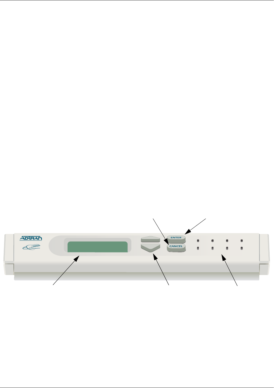
4. REVIEWING THE FRONT PANEL DESIGN
The front panel contains the display LCD, the scroll selection buttons, the enter and cancel buttons and sta-
tus LEDs. The LEDs provide visual information about the TRACER 2210/3202 system. Figure 1 identifies
the LCD, the various buttons, and the LEDs.
Figure 1. TRACER 2210/3202 Front Panel Layout
Front Panel LEDs
With the TRACER 2210/3202 powered-on, the front panel LEDs provide visual information about the
status of the TRACER 2210/3202 system. Table 1 provides a brief description of the front panel features,
TRACER 2210
PLAN B
PLAN A CHAN RF DWN TEST
V.35 RF LOW CABLE
Display LCD Scroll Buttons Status LEDs
Enter Button
Cancel Button

TRACER 2210/3202 System Manual Section 3, Engineering Guidelines
61280012L1-1A © 2001 ADTRAN, Inc. 27
and Table 2 on page 27 provides detailed information about the LEDs.
Table 1. TRACER 2210/3202 Front Panel Description
Feature Description
Display LCD Displays all menu operations and data
Scroll Buttons Use the Up and Down arrows to traverse through menu items
Enter Button Use the Enter button to select the highlighted menu
Cancel Button Use the Cancel button to escape to the previous menu
Status LEDs Provides status information about the system
Table 2. TRACER 2210/3202 LEDs
For these LEDs... This color light... Indicates that...
PLAN A Green (solid) the TRACER 3202 RIU is transmitting on Frequency Plan A.
Off the TRACER 3202 RIU is not transmitting on Frequency
Plan A.
PLAN B Green (solid) the TRACER 3202 RIU is transmitting on Frequency Plan B.
Off the TRACER 3202 RIU is not transmitting on Frequency
Plan B.
CHAN Green (solid) the TRACER 3202 RIU is transmitting on Frequency
Channel 1.
Amber (solid) the TRACER 3202 RIU is transmitting on Frequency
Channel 2.
V.35 Green (blinking) there is activity on the V.35 data port.
RF DWN Red (solid) there is a communication problem between the local and
remote 2210 and 3202 systems.
RF LOW Red (solid) the RSSI level is below suggested minimum threshold.
TEST Amber (solid) there is an active test being performed by the system or there
is an active loopback.
CABLE Green (solid) the cable between the TRACER 2210 and 3202 units is good.
Off there is a problem with the cable connecting the TRACER
2210 and 3202 units.
Section 3, Engineering Guidelines TRACER 2210/3202 System Manual
28 © 2001 ADTRAN, Inc. 61280012L1-1A
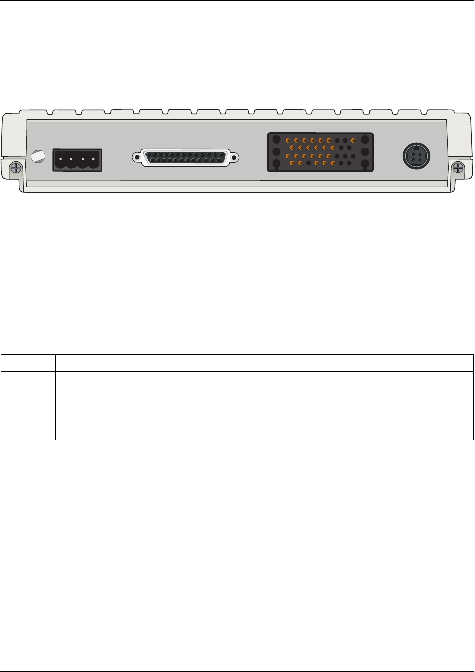
5. REVIEWING THE TRACER 2210 REAR PANEL DESIGN
The TRACER 2210 rear panel contains a terminal block labeled, RADIO, for connecting to the TRACER
3202 unit, an RS-232 port for accessing the unit via a terminal menu, a V.35 interface for connecting DTE
equipment, and a four pin power connector.
Figure 2. TRACER 2210/3202 Rear Panel Layout
RADIO Connector
The RADIO connector (terminal block) connects to the TRACER 3202 RIU using the custom cable
assembly (see Figure 1 on page 33). The RADIO connection follows, and Table 3 shows the pinout.
Connector type Terminal Block
Table 3. RADIO Connector Pinout
PIN NAME DESCRIPTION
1 RX + RECEIVE DATA - POSITIVE POLARITY
2 RX – RECEIVE DATA - NEGATIVE POLARITY
3 TX + TRANSMIT DATA - POSITIVE POLARITY
4 TX – TRANSMIT DATA - NEGATIVE POLARITY
1 2 3 4
R
A
DIO
R
S
232
V.35 N
x
56/6 4
26V
A
C
C
T
60HZ, 5
A

TRACER 2210/3202 System Manual Section 3, Engineering Guidelines
61280012L1-1A © 2001 ADTRAN, Inc. 29
RS-232 Connection
The RS-232 connector provides a female DB-25 terminal connection, which is used for terminal access to
the TRACER 2210/3202 system. The RS-232 port provides the following functions:
• Accepts EIA-232 input from a PC or terminal for controlling the TRACER 2210/3202 system.
• Operates at 9600 bps
Table 4 on page 29 shows the pinout.
V.35 Nx56/64 Connection
The V.35 Nx56/64 connector provides a female V.35 connection, which is used when connecting DTE
equipment to the TRACER 2210/3202 system. The V.35 port provides the following functions:
• Operates at data rates from 56 kbps (1, 56k DS0) to 1.536 Mbps (24, 64k DS0s).
Table 5 on page 29 shows the pinout.
Connector type (USOC) DB-25
Table 4. RS-232 Connection Pinout
PIN NAME DESCRIPTION
1, 7 GND GROUND
2 TX TRANSMIT
3 RX RECEIVE
4 RTS REQUEST TO SEND
5 CTS CLEAR TO SEND
6 — UNUSED
8 CD CARRIER DETECT
9-19 — UNUSED
20 DTR DATA TERMINAL READY
21 — UNUSED
22 RI RING INDICATOR
23-25 — UNUSED
Connector type V.35 Winchester
Table 5. V.35 Connector Pinout
Pin CCITT Signal Description Pin CCITT Signal Description
A 101 Shield (Ground) T 104 Transmit Clock (B)
B 102 Transmit Data (A) V 115 Clear to Send (B)
C 105 Received Data (A) X 115 Transmit Data (B)
Section 3, Engineering Guidelines TRACER 2210/3202 System Manual
30 © 2001 ADTRAN, Inc. 61280012L1-1A
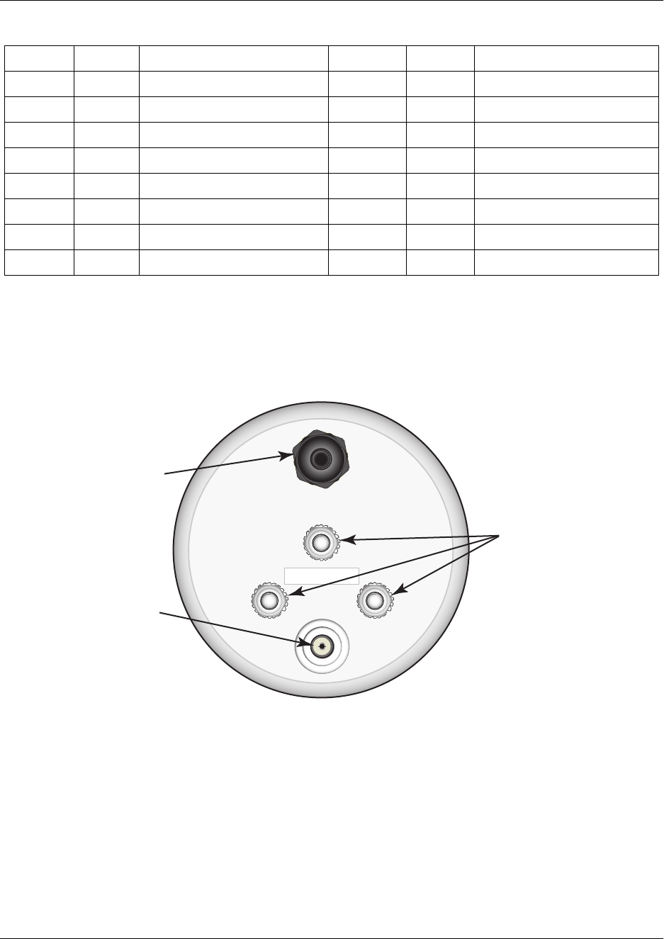
6. REVIEWING THE TRACER 3202 DESIGN
The TRACER 3202 RIU is a mast mount, cylindrical unit which serves as an environmentally controlled
housing for the RF receiver and RF transmitter. Figure 3 shows the TRACER 3202 base.
Figure 3. TRACER 3202 Base
D 106 Request to Send (A) P 103 Transmit Clock (A)
E 107 Clear to Send (A) S 103 Received Data (B)
F 109 DCE Ready (A) Y 114 Receive Clock (A)
H — Signal Ground AA 114 Local Loopback
J — Carrier Detect (A) U 113 Request to Send (B)
L — Received Clock (B) W 113 DTE Ready (A)
N — Carrier Detect (B) NN & K — Remote Loopback
R 104 Ext. Transmit Clock (B)
Table 5. V.35 Connector Pinout (Continued)
Pin CCITT Signal Description Pin CCITT Signal Description
PLAN B
Power/Data
Connector
Ground
Terminals
N - Type
RF Connector

61280012L1-1A © 2002 ADTRAN, Inc. 31
NETWORK TURNUP PROCEDURE
CONTENTS
Introduction . . . . . . . . . . . . . . . . . . . . . . . . . . . . . . . . . . . . . . . . . . . . . . . . . . . . . . . . . . . . . . . . . . . . 32
Tools Required . . . . . . . . . . . . . . . . . . . . . . . . . . . . . . . . . . . . . . . . . . . . . . . . . . . . . . . . . . . . . . . . . 32
Unpack and Inspect the System . . . . . . . . . . . . . . . . . . . . . . . . . . . . . . . . . . . . . . . . . . . . . . . . . . . 32
Contents of ADTRAN Shipment . . . . . . . . . . . . . . . . . . . . . . . . . . . . . . . . . . . . . . . . . . . . . . . . . 32
Customer Provides . . . . . . . . . . . . . . . . . . . . . . . . . . . . . . . . . . . . . . . . . . . . . . . . . . . . . . . . . . . 33
Cable Assembly . . . . . . . . . . . . . . . . . . . . . . . . . . . . . . . . . . . . . . . . . . . . . . . . . . . . . . . . . . . . . . . . 33
Channel Selection . . . . . . . . . . . . . . . . . . . . . . . . . . . . . . . . . . . . . . . . . . . . . . . . . . . . . . . . . . . . . . 34
Grounding Instructions . . . . . . . . . . . . . . . . . . . . . . . . . . . . . . . . . . . . . . . . . . . . . . . . . . . . . . . . . . 34
Supplying Power to the Unit . . . . . . . . . . . . . . . . . . . . . . . . . . . . . . . . . . . . . . . . . . . . . . . . . . . . . . 35
TRACER 2210 DIU . . . . . . . . . . . . . . . . . . . . . . . . . . . . . . . . . . . . . . . . . . . . . . . . . . . . . . . . . . . 35
TRACER 3202 RFU . . . . . . . . . . . . . . . . . . . . . . . . . . . . . . . . . . . . . . . . . . . . . . . . . . . . . . . . . . 36
Mounting Options . . . . . . . . . . . . . . . . . . . . . . . . . . . . . . . . . . . . . . . . . . . . . . . . . . . . . . . . . . . . . . . 36
TRACER 2210 DIU . . . . . . . . . . . . . . . . . . . . . . . . . . . . . . . . . . . . . . . . . . . . . . . . . . . . . . . . . . . 36
TRACER 3202 RFU . . . . . . . . . . . . . . . . . . . . . . . . . . . . . . . . . . . . . . . . . . . . . . . . . . . . . . . . . . 36
FIGURES
Figure 1. Cable Assembly Instructions . . . . . . . . . . . . . . . . . . . . . . . . . . . . . . . . . . . . . . . . . . . . . 33
Figure 2. Bandwidth Division. . . . . . . . . . . . . . . . . . . . . . . . . . . . . . . . . . . . . . . . . . . . . . . . . . . . . 34
Figure 3. Connecting the TRACER 3202 Rope Tethers . . . . . . . . . . . . . . . . . . . . . . . . . . . . . . . . 36
Section 4, Network Turnup Procedure TRACER 2210/3202 System Manual
32 © 2002 ADTRAN, Inc. 61280012L1-1A
1. INTRODUCTION
This section discusses the installation process of the TRACER 2210/3202 system.
2. TOOLS REQUIRED
The tools required for the installation of the TRACER 2210/3202 are:
• Wire stripper (for cable assembly)
• Wire cutter (for cable assembly)
• Crimping tool (for cable assembly)
• #2 Phillips screwdriver (for cable assembly)
3. UNPACK AND INSPECT THE SYSTEM
Each TRACER 2210/3202 is shipped in its own cardboard shipping carton. Open each carton carefully and
avoid deep penetration into the carton with sharp objects.
After unpacking the unit, inspect it for possible shipping damage. If the equipment has been damaged in
transit, immediately file a claim with the carrier, then contact ADTRAN Customer Service (see Warranty
and Customer Service information in the front of this manual).
Contents of ADTRAN Shipment
Your ADTRAN shipment includes the following items:
• (1) TRACER 2210 Data Interface Unit (DIU)
• (1) 6’ Wallmount power supply (for DIU)
• (1) TRACER 3202 RF Mast Unit (RIU)
• (1) Pre-threaded mast unit bracket
• (2) Bracket clamps
• (4) CPC crimping pins
• (1) Terminal block for custom cable assembly - inside TRACER 2210 box
• (1) The TRACER 2210/3202 System CD including the User Manual and Quick Start Guide - inside
TRACER 2210 box
Changes or modifications not expressly approved by ADTRAN could void the user’s
authority to operate the equipment.
To prevent electrical shock, do not install equipment in a wet location or during a
lightning storm.
TRACER 2210/3202 System Manual Section 4, Network Turnup Procedure
61280012L1-1A © 2002 ADTRAN, Inc. 33
Customer Provides
The following items are necessary for the installation of the TRACER 2210/3202 system and are not
provided by ADTRAN:
• 4 Conductor, 22 or 24 AWG, UV-resistant cable (maximum length 700 ft or 600 ft, respectively)
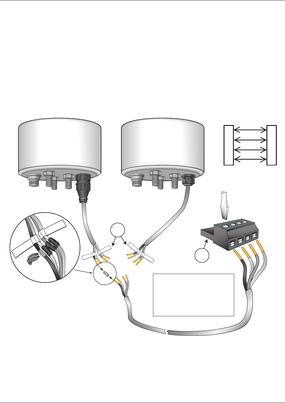
4. CABLE ASSEMBLY
The following provides pictorial instructions for assembling the cable between the TRACER 2210 and
3202 units. The cable length and material should be customized to suit the needs of the application. All of
the necessary connector pieces are supplied by ADTRAN in your TRACER 2210/3202 shipment.
Figure 1. Cable Assembly Instructions
1
2
3
4
1
2
3
4
P1 P2
Schematic
1234
P1
P2
1 & 2
3 & 4
1 & 2
3 & 4
1 & 2
3 & 4
Tracer 3202 base (Version 1) Tracer 3202 base (Version 2)
1. Crimp each crimp tube and wrap
individually with electrical tape to
prevent shorting
2. Wrap the complete bundle with
electrical tape to protect from
outside elementsmosture.
Warning: When connecting the
supplied cable to your in house
wiring, do not attach the block
assembly to the TRACER 2210
base unit until cable assembly is
complete.
Section 4, Network Turnup Procedure TRACER 2210/3202 System Manual
34 © 2002 ADTRAN, Inc. 61280012L1-1A
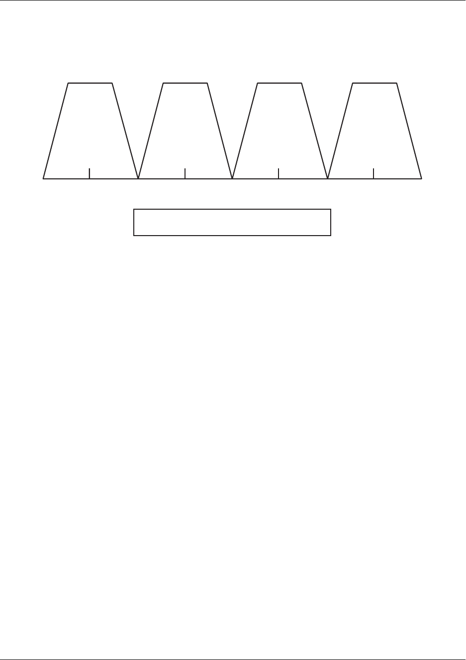
5. CHANNEL SELECTION
The FCC has allocated 125 MHz of spectrum in the band in which the TRACER 2210/3202 operates.
Figure 2 illustrates the bandwidth division.
Figure 2. Bandwidth Division
To designate the utilization of the ISM bandwidth, there are four different channel plans, labeled A1, B1,
A2 and B2. The letter of each channel plan setting is preset by the factory and refers to the physical
configuration of the diplexer filter inside the environmental housing. The second portion or letter of the
channel plan refers to the receive and transmit oscillator frequencies in the radio. Numbering the lobes in
Figure 2 from left to right, a channel plan of A1 or B1 refers to transmitting and receiving on the first and
third lobes. Likewise a channel plan of A2 or B2 refers to the transmitting and receiving of the second and
fourth lobes of Figure 2. There are two rules for successful 3202 configuration.
1. The letter of the channel plan must be different on both ends.
2. The frequency number must match.
An A1 Radio must have a B1 Radio on the other end and a B2 Radio must have an A2 Radio on the other
end.
6. GROUNDING INSTRUCTIONS
The following provides grounding instruction information from the Underwriters’ Laboratory UL 1950
Standard for Safety of Information Technology Equipment Including Electrical Business Equipment, of
July 28, 1995.
An equipment grounding conductor that is not smaller in size than the ungrounded branch-circuit supply
conductors is to be installed as part of the circuit that supplies the product or system. Bare, covered, or
insulated grounding conductors are acceptable. Individually covered or insulated equipment grounding
conductors shall have a continuous outer finish that is either green, or green with one or more yellow
stripes. The equipment grounding conductor is to be connected to ground at the service equipment.
The attachment-plug receptacles in the vicinity of the product or system are all to be of a grounding type,
A1
5736 MHz
A2
5748 MHz
B1
5824 MHz
B2
5836 MHz
Channel Plan describes which lobe is transmitted upon.
Example: A1 will transmit at A1 lobe and receive at B1.
TRACER 2210/3202 System Manual Section 4, Network Turnup Procedure
61280012L1-1A © 2002 ADTRAN, Inc. 35
and the equipment grounding conductors serving these receptacles are to be connected to earth ground at
the service equipment.
A supplementary equipment grounding conductor shall be installed between the product or system and
ground that is in addition to the equipment grounding conductor in the power supply cord.
The supplementary equipment grounding conductor shall not be smaller in size than the ungrounded
branch-circuit supply conductors. The supplementary equipment grounding conductor shall be connected
to the product at the terminal provided, and shall be connected to ground in a manner that will retain the
ground connection when the product is unplugged from the receptacle. The connection to ground of the
supplementary equipment grounding conductor shall be in compliance with the rules for terminating
bonding jumpers at Part K or Article 250 of the National Electrical Code, ANSI/NFPA 70. Termination of
the supplementary equipment grounding conductor is permitted to be made to building steel, to a metal
electrical raceway system, or to any grounded item that is permanently and reliably connected to the
electrical service equipment ground.
The supplemental grounding conductor shall be connected to the equipment using a number 8 ring terminal
and should be fastened to the grounding lug provided on the rear panel of the equipment. The ring terminal
should be installed using the appropriate crimping tool (AMP P/N 59250 T-EAD Crimping Tool or
equivalent.)
7. SUPPLYING POWER TO THE UNIT
TRACER 2210 DIU
The TRACER 2210 comes equipped with an AC/AC adapter with a 2 prong plug for connecting to a
properly grounded power receptacle. As shipped, the TRACER 2210 is set to factory default settings. To
power-up the unit, ensure that the TRACER 2210 is connected to an appropriate power source. There is no
On/Off switch on the TRACER 2210 unit.
Grounding terminals for the TRACER 2210/3202 are located on the bottom of the
TRACER 3202 mast unit.
• This unit shall be installed in accordance with Article 400 and 364.8 of the NEC NFPA
70 when installed outside of a Restricted Access Location (i.e., central office, behind a
locked door, service personnel only area).
• Power to the TRACER 2210 AC system must be from a grounded 90-130 VAC, 50/60
Hz source.
• The power receptacle uses double-pole, neutral fusing.
• Maximum recommended ambient operating temperature is 50 ºC.
Section 4, Network Turnup Procedure TRACER 2210/3202 System Manual
36 © 2002 ADTRAN, Inc. 61280012L1-1A
TRACER 3202 RIU
Power for the TRACER 3202 RIU is provided by the TRACER 2210 DIU over a twisted pair. To power-up
the TRACER 3202, properly connect the RIU to the DIU using the custom cable assembly (see Cable
Assembly on page 33).
8. MOUNTING OPTIONS
TRACER 2210 DIU
The TRACER 2210 DIU may be installed for tabletop or wall-mount configuration. Use the 4 mounting
slots on the base of the TRACER 2210 housing for wall-mount configurations.
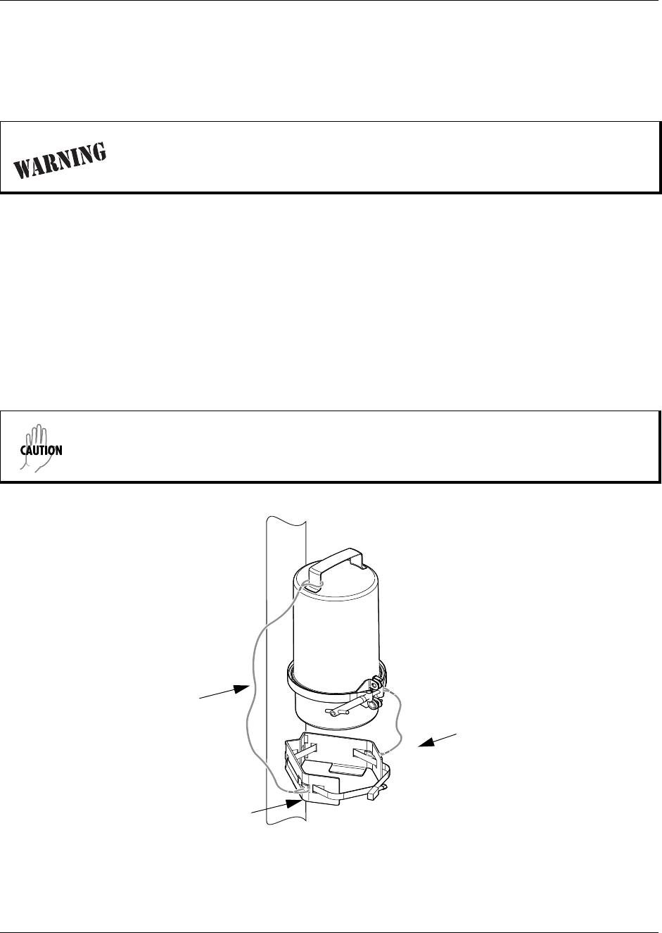
TRACER 3202 RIU
The TRACER 3202 RIU is provided for mast mount installation. Use the provided mounting bracket when
installing the unit on the external pole or tower.
Figure 3. Connecting the TRACER 3202 Rope Tethers
Disconnect power from the TRACER 2210 before connecting to the TRACER 3202
RIU. Power-up the TRACER 2210 after the cable assembly has been properly
created and connected to both units.
Connect the provided wire rope tethers around the L-shaped cutout on the mounting
bracket to protect the housing clamp and housing cover from falling during installation
and maintenance (see Figure 3).
Housing Clamp Tether
Housing Cover Tether
Mounting Bracket

61280012L1-1A © 2002 ADTRAN, Inc. 37
USER INTERFACE GUIDE
CONTENTS
Navigating the Terminal Menu . . . . . . . . . . . . . . . . . . . . . . . . . . . . . . . . . . . . . . . . . . . . . . . . . . . . 38
Terminal Menu Window . . . . . . . . . . . . . . . . . . . . . . . . . . . . . . . . . . . . . . . . . . . . . . . . . . . . . . . 38
Navigating using the Keyboard Keys . . . . . . . . . . . . . . . . . . . . . . . . . . . . . . . . . . . . . . . . . . . . . 38
Terminal Menu and System Control . . . . . . . . . . . . . . . . . . . . . . . . . . . . . . . . . . . . . . . . . . . . . . . .39
Selecting the Appropriate Menu . . . . . . . . . . . . . . . . . . . . . . . . . . . . . . . . . . . . . . . . . . . . . . . . . 39
Menu Descriptions . . . . . . . . . . . . . . . . . . . . . . . . . . . . . . . . . . . . . . . . . . . . . . . . . . . . . . . . . . . . . . 39
>Status . . . . . . . . . . . . . . . . . . . . . . . . . . . . . . . . . . . . . . . . . . . . . . . . . . . . . . . . . . . . . . . . . . . . 40
>Config . . . . . . . . . . . . . . . . . . . . . . . . . . . . . . . . . . . . . . . . . . . . . . . . . . . . . . . . . . . . . . . . . . . . 41
>Util. . . . . . . . . . . . . . . . . . . . . . . . . . . . . . . . . . . . . . . . . . . . . . . . . . . . . . . . . . . . . . . . . . . . . . . 44
>Test . . . . . . . . . . . . . . . . . . . . . . . . . . . . . . . . . . . . . . . . . . . . . . . . . . . . . . . . . . . . . . . . . . . . . . 44
FIGURES
Figure 1. Top-Level Terminal Menu Window . . . . . . . . . . . . . . . . . . . . . . . . . . . . . . . . . . . . . . . . 38
Section 5, User Interface Guide TRACER 2210/3202 System Manual
38 © 2002 ADTRAN, Inc. 61280012L1-1A
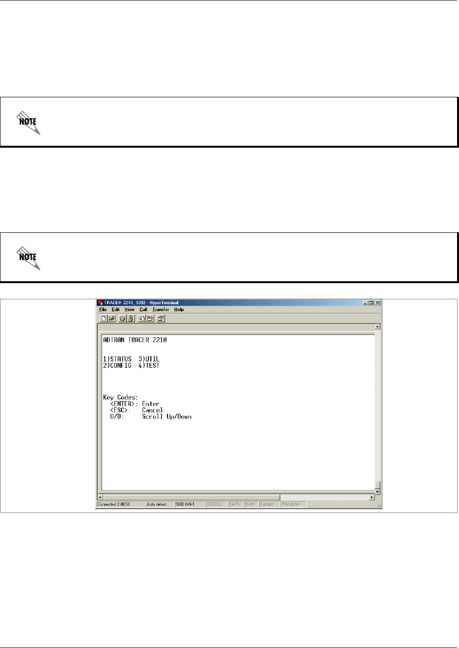
1. NAVIGATING THE TERMINAL MENU
The TRACER 2210/3202 menu system can be accessed via the front panel or through terminal menus
when connected to the DB-25 terminal interface located on the rear panel of the TRACER 2210 unit. The
menu listings and descriptions found in this section refer to the menus as listed when connected through
the terminal interface.
Terminal Menu Window
The TRACER 2210/3202 uses hierarchical menus to access its many features. The main menu level (see
Figure 1) leads to submenus. All menu operations can be displayed in either a terminal window or in the
LCD window on the front panel of the TRACER 2210 unit.
Figure 1. Top-Level Terminal Menu Window
Navigating using the Keyboard Keys
You can use various keystrokes to move through the terminal menu, to manage a terminal menu session,
and to configure the system.
Minor differences in the menu listings will occur when viewing the menus through the
front panel.
After connecting a VT100 terminal to the 2210, press the spacebar to redraw the current
screen. VT 100 access will not be possible until this step is performed.

TRACER 2210/3202 System Manual Section 5, User Interface Guide
61280012L1-1A © 2002 ADTRAN, Inc. 39
Moving through the Menus
Session Management Keystrokes
2. TERMINAL MENU AND SYSTEM CONTROL
Selecting the Appropriate Menu
The terminal menu is the access point to all other operations. Each terminal menu item has several
functions and submenus that identify and provide access to specific operations and parameters. Use the
chart below to help select the appropriate terminal menu.
3. MENU DESCRIPTIONS
The remainder of this section describes the TRACER 2210/3202 menus and submenus. Menu trees for the
TRACER 2210/3202 can be found on the documentation CD.
To do this.. Press this key...
Move up to select items U
Move down to select items D
Edit a selected menu item Enter
Cancel an edit Escape
Ascend one menu level Escape
To do this.. Press this key...
Log into a session Spacebar
Refresh the screen
To save time, only the portion of the screen that has changed is refreshed. This
option should only be necessary if the display picks up incorrect characters
Spacebar
To do this.. Go to this menu...
View the current status of the V.35, radio, or alarms STATUS
Configure the network parameters including clocking and V.35 data rate CONFIG
View the current software revision of the unit and set the passcode for front panel
access
UTIL
Initiate a V.35 test and review the current status TEST
The hierarchical menu structure of the TRACER 2210/3202 system is depicted below as
follows:
> MAIN MENU
> MAIN MENU > SUBMENU
> MAIN MENU > SUBMENU > SUB-SUBMENU

Section 5, User Interface Guide TRACER 2210/3202 System Manual
40 © 2002 ADTRAN, Inc. 61280012L1-1A
>STATUS
Provides status information for the TRACER 3202 RIU as well as performance statistics for the V.35.
STATUS > RSSI
RSSI (Received Signal Strength Indicator) is an acronym referring to the relative strength of the signal
currently received at the antenna. A high RSSI is desirable for good system performance. RSSI is
displayed on the front panel LCD and the terminal menus as a solid bar extending between two brackets.
When the bar fully covers the space between the brackets, a maximum RSSI level is conveyed. When the
space between the brackets is empty, a minimum RSSI is conveyed. This menu item refers to the near
TRACER 3202.
STATUS > FAR RSSI
RSSI (Received Signal Strength Indicator) is an acronym referring to the relative strength of the signal
currently received at the antenna. A high RSSI is desirable for good system performance. RSSI is
displayed on the front panel LCD and the terminal menus as a solid bar extending between two brackets.
When the bar fully covers the space between the brackets, a maximum RSSI level is conveyed. When the
space between the brackets is empty, a minimum RSSI is conveyed. This menu refers to the TRACER
3202 on far-end of the system.
STATUS > PERFRM REPORTS
Provides performance data for the 2210 to 3202 connection. The data displayed is data accumulated over
the last 15 minutes and over the last 24 hours of operation.
STATUS > PERFRM REPORTS > SES
Displays the number of severely errored seconds occurring in the last 15 minutes and 24 hours. A severely
errored second is defined as any second that contains more than 2.5 code violations.
STATUS > PERFRM REPORTS > ES
Displays the number of errored seconds occurring in the last 15 minutes and 24 hours. An errored second is
defined as any second that contains a code violation.
STATUS > PERFRM REPORTS > %AV
Displays the percentage of available seconds in the last 15 minutes and 24 hours of operation. An available
second is defined as any second of operation that the unit is not in an alarm condition.
STATUS > PERFRM REPORTS > %EF
Displays the percentage of error free seconds in the last 15 minutes and 24 hours of operation. An error
free second is defined as any available second that does not contain a code violation.
STATUS > PERFRM REPORTS > RESET PERF CNTRS
Resets the display for the performance report counters. Clearing the counter display does not affect the 15
minute or 24 hour counter totals.

TRACER 2210/3202 System Manual Section 5, User Interface Guide
61280012L1-1A © 2002 ADTRAN, Inc. 41
>CONFIG
The Configuration menu is used to set the TRACER 2210/3202 operational configuration, including all of
the network interface parameters, the allocation of the DS0s, and the V.35 port parameters.
CONFIG > DIU
Contains configuration parameters for the TRACER 2210 DIU.
CONFIG > DIU > CLOCK SOURCE
Configures the clock source for transmission toward the network. The TRACER 2210 is operable from
various clock sources permitting it to perform properly in many different applications.
Choices: INTERNAL, FAR END, AUTO, DTE
The clocking option selected always designates the clock source for transmission. Clocking necessary for
receiving data is always recovered from incoming data.
CONFIG > V.35
Contains configuration and operational parameters for the TRACER 2210 DIU V.35 interface.
CONFIG > V.35 > V.35 STEPSIZE 56/64 KPBS
Configures the data rate step size for the TRACER 2210 DIU V.35 interface. The available step sizes for
the V.35 interface are 56 kbps or 64 kbps.
Choices: 56 or 64
CONFIG > V.35 > V.35 RATE NX64
Configures the data rate for the TRACER 2210 DIU V.35 interface. The data rate for the TRACER 2210
DIU V.35 interface is the value of N (1 to 24) multiplied by the step size of the interface (see above). Thus
the available data rates range from 56 kbps (N = 1, step size = 56kps) to 1.536 Mbps (N=24, step size =
64kbps).
Choices: 1 to 24
Section 5, User Interface Guide TRACER 2210/3202 System Manual
42 © 2002 ADTRAN, Inc. 61280012L1-1A
CONFIG > V.35 > V.35 TX CLK
Controls the clock used by the TRACER 2210 DIU to accept the transmit (TX) data from the DTE. Most
applications will allow for this to be set to INTERNAL. If the cable between the TRACER 2210 DIU and the
DTE equipment is long (causing a phase shift in the data) the clock can be selected as INT-INV
(Internal/Inverted). This switches the phase of the clock which should compensate for a long cable. The
AUTO setting will allow the TRACER 2210 DIU to automatically detect the delay from the DTE device to
the V.35 interface of the DIU and set the proper phase of the clock. This feature will automatically select
between the INTERNAL and INT-INV settings. If the DTE provides a clock with TX data, the clock selection
should be set to EXTERNAL. When set to EXTERNAL, the TRACER 2210 DIU will require an externally
supplied clock to accept TX data
Choices: AUTO, INT-INV, EXTERNAL, INTERNAL
CONFIG > V.35 > DATA
Used to control the inverting of the DTE data. Inverting data can be useful when operating with an HDLC
protocol (due to excessive zeros). Enabling data inversion helps ensure ones (1s) density.
Choices: NORMAL, INVERT
CONFIG > V.35 > CTS
Used to control the characteristics of the Clear To Send (CTS) signal on the V.35 interface. In normal
operation CTS follows Request To Send (RTS) and is only asserted after RTS. Selecting the FORCE ON
setting configures the TRACER 2210 DIU to permanently assert the CTS signal on the V.35 interface.
Choices: NORMAL, FORCE ON
CONFIG > V.35 > DCD
Used to control the characteristics of the Data Carrier Detect (DCD) signal on the V.35 interface. In normal
operation DCD is turned off when a TRACER 2210 DIU self test is active, when no DS0s are mapped to
the V.35 interface, or when the radio interface is unavailable. Selecting the FORCE ON setting configures
the TRACER 2210 DIU to permanently assert the DCD signal on the V.35 interface
Choices: NORMAL, FORCE ON
CSU/DSU equipment on both ends must be configured for data inversion if it is required.

TRACER 2210/3202 System Manual Section 5, User Interface Guide
61280012L1-1A © 2002 ADTRAN, Inc. 43
CONFIG > V.35 > DSR
Used to control the characteristics of the Data Set Ready (DSR) signal on the V.35 interface. In normal
operation DSR is turned off during all testing and when no DS0s are mapped to the V.35 interface.
Selecting the FORCE ON setting configures the TRACER 2210 DIU to permanently assert the DSR signal
on the V.35 interface.
Choices: NORMAL, FORCE ON
CONFIG > RADIO
Provides operational parameters for the TRACER 3202 RIU.
CONFIG > RADIO > TRANSMIT POWER
Controls the power the TRACER 3202 transmits through the antenna. A solid bar extends between two
brackets in lengths corresponding to the selected transmit power. When the transmit power is set so that the
bar fully covers the space between the brackets, a maximum transmit power level has be selected. When
the transmit power is set so that the space between the brackets is empty, a minimum transmit power. This
menu refers to the near TRACER 3202.
CONFIG > RADIO > CHANNEL PLAN
Displays the far end TRACER 3202 unit channel plan as either A1, A2, B1, or B2. The TRACER 3202
RIU comes pre-configured as either channel plan A or B. Using the terminal menus, select one of the
following frequency plans:
A1: Transmit 5.736 Ghz Receive 5.824 Ghz
A2: Transmit 5.748 Ghz Receive 5.836 Ghz
B1: Transmit 5.824 Ghz Receive 5.736 Ghz
B2: Transmit 5.836 Ghz Receive 5.748 Ghz
CONFIG > RADIO > FAR TRANSMIT PWR
Controls the power the TRACER 3202 transmits through the antenna. A solid bar extends between two
brackets in lengths corresponding to the selected transmit power. When the transmit power is set so that the
bar fully covers the space between the brackets, a maximum transmit power level has be selected. When
the transmit power is set so that the space between the brackets is empty, a minimum transmit power. This
menu refers to the TRACER 3202 on far-end of the system.
CONFIG > RADIO > FAR CHANNEL PLAN
Displays the far end TRACER 3202 unit channel plan as either A1, A2, B1, or B2. The TRACER 3202
RIU comes pre-configured as either channel plan A or B and the exact frequency plan is configured using
the local TRACER 2210 unit. The following frequency plans are available:
A1: Transmit 5.736 Ghz Receive 5.824 Ghz
A2: Transmit 5.748 Ghz Receive 5.836 Ghz
B1: Transmit 5.824 Ghz Receive 5.736 Ghz
B2: Transmit 5.836 Ghz Receive 5.748 Ghz
Section 5, User Interface Guide TRACER 2210/3202 System Manual
44 © 2002 ADTRAN, Inc. 61280012L1-1A
>UTIL
The Utility menu contains display information for the TRACER 2210/3202 system as well as
configuration parameters for system settings.
UTIL > SOFTWARE REV
Displays the current software revision level and the software checksum of the TRACER 2210 DIU. This
information will be needed when requesting assistance from ADTRAN Customer service or when updates
are needed.
UTIL > REINIT UNIT
Reinitializes the unit and performs a system self-test. Using the REINIT UNIT setting is the same as power
cycling the unit.
UTIL > SET PASSCODE
Allows the user to add, change, or delete a passcode for the TRACER 2210 DIU front panel.
UTIL > KEY PAD LOCK
Allows the user to lock the front panel keypad access. Locking the keypad will require a terminal session
to access the TRACER 2210 DIU.
Choices: UNLOCKED, LOCKED
UTIL > FACT RESTORE
Restores all unit parameters to the factory default settings.
>TEST
The Test menu is used to initiate different types of tests for the unit and view the results. Test results can be
viewed via the LCD display on the front panel of the unit or the terminal menu.
This menu item is not used to restore the factory default settings for all parameters.

TRACER 2210/3202 System Manual Section 5, User Interface Guide
61280012L1-1A © 2002 ADTRAN, Inc. 45
TEST > LOOPBACKS
Configures the TRACER 2210 DIU to initiate a particular loopback. Selecting a Far 2210 loopback
configures the DIU to loop the far end unit. This will constitute a full system test. Selecting a 2210 To
Radio loopback configures the DIU to loop the data stream at the unit back towards the 3202 RIU. This can
be used to verify the entire system when the pattern is sent from the far end through the local loopback.
Selecting the 2210 To V.35 loopback configures the DIU to loop the data stream from the 2210 back
towards the V.35 interface. This can be used to verify the cable between the DIU and the DTE equipment.
Selecting the Radio Cable loopback provides a loop in the data stream at the data framer in the TRACER
3202 RIU back to the TRACER 2210 radio interface. Sending the pattern from the TRACER 2210 DIU
through the Radio Cable loopback will verify the integrity of the cable connecting the two units.
CHOICES: NO PATTERN, 511 PATTERN, QRSS PATTERN, AND 1:8 PATTERN
TEST > TEST PATTERN
Sets the pattern for the active test and initiates the transmission of the pattern. Selecting the 511 Pattern
will generate the standard DTE 511 data pattern from the TRACER 2210. This will activate the 511 error
counter but not reset the value. Selecting the QRSS pattern will generate a quasi-random signal source data
pattern from the TRACER 2210. The 1:8 pattern will generate a binary one followed by eight binary zeros.
Choices: ALL ONES, ALL ZEROS, 511 PATTER, AND QRSS
TEST > CLR PATTN ERRORS
Displays the count of the pattern errors. This counter is initiated when a pattern is selected in the Test
Pattern field. To clear the pattern error counter press <Enter>.
TEST > INSERT PATTN ERRORS
Inserts an intentional pattern error in the data stream which can be tracked using the pattern error counter.
Press <Enter> to insert the error.
TEST > CLEAR TESTS
Clears all active tests (loopbacks and patterns) in the TRACER 2210/3202 system.

Section 5, User Interface Guide TRACER 2210/3202 System Manual
46 © 2002 ADTRAN, Inc. 61280012L1-1A

61280012L1-1A © 2001 ADTRAN, Inc. 47
TROUBLE SHOOTING GUIDE
CONTENTS
Overview. . . . . . . . . . . . . . . . . . . . . . . . . . . . . . . . . . . . . . . . . . . . . . . . . . . . . . . . . . . . . . . . . . . . . . . 32
2210-to-3202 Cabling Errors. . . . . . . . . . . . . . . . . . . . . . . . . . . . . . . . . . . . . . . . . . . . . . . . . . . . . . . 32
Invalid 2210 Settings . . . . . . . . . . . . . . . . . . . . . . . . . . . . . . . . . . . . . . . . . . . . . . . . . . . . . . . . . . . . . 32
Timing Settings . . . . . . . . . . . . . . . . . . . . . . . . . . . . . . . . . . . . . . . . . . . . . . . . . . . . . . . . . . . . . . . 32
V.35 Settings. . . . . . . . . . . . . . . . . . . . . . . . . . . . . . . . . . . . . . . . . . . . . . . . . . . . . . . . . . . . . . . . . 32
Invalid DTE Settings . . . . . . . . . . . . . . . . . . . . . . . . . . . . . . . . . . . . . . . . . . . . . . . . . . . . . . . . . . . . . 33
RF Errors . . . . . . . . . . . . . . . . . . . . . . . . . . . . . . . . . . . . . . . . . . . . . . . . . . . . . . . . . . . . . . . . . . . . . . 33
Loopback Options . . . . . . . . . . . . . . . . . . . . . . . . . . . . . . . . . . . . . . . . . . . . . . . . . . . . . . . . . . . . . . . 33
2210 to DTE (V.35) Loopback. . . . . . . . . . . . . . . . . . . . . . . . . . . . . . . . . . . . . . . . . . . . . . . . . . . . 34
2210-to-Radio Loopback. . . . . . . . . . . . . . . . . . . . . . . . . . . . . . . . . . . . . . . . . . . . . . . . . . . . . . . . 34
Radio Cable Loopback . . . . . . . . . . . . . . . . . . . . . . . . . . . . . . . . . . . . . . . . . . . . . . . . . . . . . . . . . 34
Far 2210 Loopback . . . . . . . . . . . . . . . . . . . . . . . . . . . . . . . . . . . . . . . . . . . . . . . . . . . . . . . . . . . . 34
Test Patterns . . . . . . . . . . . . . . . . . . . . . . . . . . . . . . . . . . . . . . . . . . . . . . . . . . . . . . . . . . . . . . . . . . . 34
1-in-8 Pattern . . . . . . . . . . . . . . . . . . . . . . . . . . . . . . . . . . . . . . . . . . . . . . . . . . . . . . . . . . . . . . . . 34
511 Pattern . . . . . . . . . . . . . . . . . . . . . . . . . . . . . . . . . . . . . . . . . . . . . . . . . . . . . . . . . . . . . . . . . . 34
QRSS Pattern . . . . . . . . . . . . . . . . . . . . . . . . . . . . . . . . . . . . . . . . . . . . . . . . . . . . . . . . . . . . . . . . 34
Step-by-Step Troubleshooting . . . . . . . . . . . . . . . . . . . . . . . . . . . . . . . . . . . . . . . . . . . . . . . . . . . . . 35
Installing/Troubleshooting the TRACER Hardware . . . . . . . . . . . . . . . . . . . . . . . . . . . . . . . . . . . . 35
Installing/Configuring DTE Hardware . . . . . . . . . . . . . . . . . . . . . . . . . . . . . . . . . . . . . . . . . . . . . . 36
FIGURES
Figure 1.. TRACER 2210/3202 Loopback Diagram . . . . . . . . . . . . . . . . . . . . . . . . . . . . . . . . . . . . . 33

Section 4, Trouble Shooting Guide TRACER 2210/3202 System Manual
48 © 2001 ADTRAN, Inc. 61280012L1-1A
1. OVERVIEW
In general, system configuration errors fall into 1 of 4 categories:
(1) 2210-to-3202 cabling errors
(2) Invalid 2210 settings
(3) DTE configuration errors
(4) RF errors
2. 2210-TO-3202 CABLING ERRORS
Ensure that the electrical connection between the cable splices and the terminal block plug on the 2210 is
correct, using an ohmmeter. If all 4 conductors are intact, ensure that the pin-out is correct for each
connector, i.e. pin 1 on the terminal block is attached to conductor 1 on the spliced cable, etc.
3. INVALID 2210 SETTINGS
Several V.35 interface options are available for the TRACER 2210 for connecting to DTE equipment (eg.
router, bridge), and its interface with the radio link.
Timing Settings
Timing settings determine how the TRACER 2210 synchronizes itself to external equipment, including the
DTE hardware attached to the V.35 port, and the remote 2210 unit on the opposite end of the radio link. A
fully synchronized and operational TRACER 2210/3202 system requires that one and only one piece of
communications equipment control timing throughout the system. The TRACER 2210 has been flexibly
designed so that either the 2210 or the attached DTE equipment can mandate timing.
Most DTE equipment will expect timing to originate from the 2210 unit. In these common applications the
factory default, or AUTO, settings stored in the 2210 will synchronize the DTE and TRACER 2210/3202
circuits together. For those DTE devices that require self-regulated system timing, the TRACER 2210
timing settings will need to be changed via the 2210 menu.
V.35 Settings
Interface-related errors may also occur if the number of 56/64 kHz sub-channels is incompatible with the
DTE hardware. To remedy this problem, set the 2210 V.35 rate within the limits of the DTE bandwidth.
There are two distinct clock circuits in the 2210. One clock circuit interfaces with the V.35 port, and the
other clock circuit interfaces with the radio channel (network). The V.35 clock setting determines whether
the V.35 port accepts (sinks) or provides (sources) the clock used to synchronize data transmission between
the DTE unit and the 2210. The 2210 internal clock setting determines whether the internal 2210
oscillator, DTE received clock, or radio interface clock is used as the internal clock source for the 2210
unit. In most applications, the default (AUTO) timing settings for these two clocks will be correct.
The TRACER 2210 is factory-configured to network timing, and so acts as standard DCE hardware when
connected via a V.35 cable to DTE hardware. When using the 2210 in non-standard applications, please
consult both the DTE hardware user’s manual and TRACER 2210 user’s manual for proper settings
information.
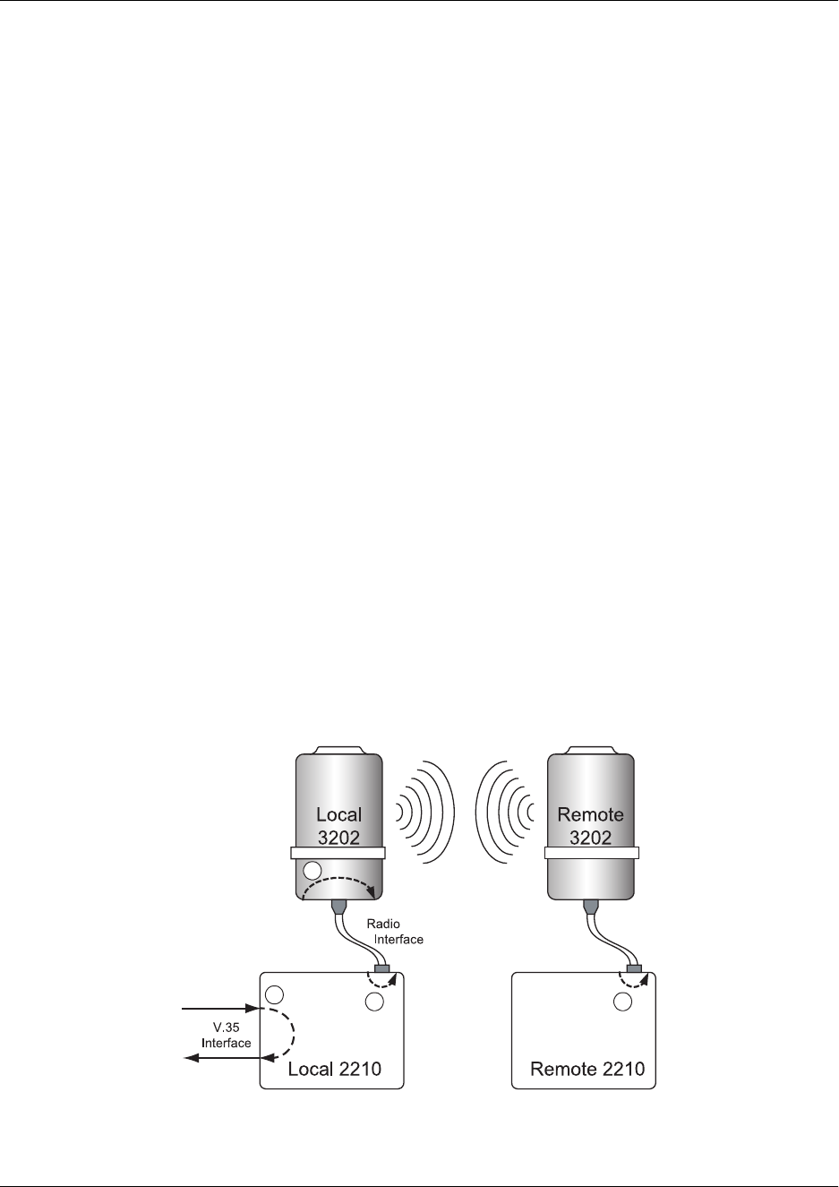
TRACER 2210/3202 System Manual Section 4, Trouble Shooting Guide
61280012L1-1A © 2001 ADTRAN, Inc. 49
4. INVALID DTE SETTINGS
It may be necessary to change certain options on the DTE hardware. Please consult the user’s manual for
your particular DTE hardware to ensure proper setup.
5. RF ERRORS
RF errors can range anywhere from a non-viable microwave path to loose RF connectors.
Non-viable path conditions could be caused by physical obstructions such as buildings, mountainous
terrain, trees, etc., as well as other physical limitations such as excessive path distances and in-band RF
interference. These types of errors are remedied by performing a detailed line-of-sight microwave path
study to determine whether or not a microwave link is feasible for the terrain and environment under
consideration.
If after performing a microwave path study the system is still not operational, ensure that the antennas are
properly aligned. Note that alignment must be achieved in both elevation and azimuth for optimal link
performance. The TRACER 2210 can be used to aid in antenna alignment by looking at the RSSI
submenu. Optimal antenna alignment will correspond to the maximum number of RSSI asterisks (or bars)
on the 2210 RSSI display.
6. LOOPBACK OPTIONS
The TRACER 2210/3202 has several data path loopback options available to assist in piece-wise
verification of data path integrity throughout the circuit. Each loopback option can be turned on/off from
the keypad menu on the 2210 unit. Enter the following menu selection to access the Loopback submenu.
4) TEST →
→→
→ 1) LOOPBACKS
The available loopback points are RADIO CABLE, 2210 TO DTE, 2210 TO RADIO, and FAR 2210.
(Figure 1 on page 49) shows the loopback locations and directions graphically.
Figure 1. TRACER 2210/3202 Loopback Diagram
1
3
24

Section 4, Trouble Shooting Guide TRACER 2210/3202 System Manual
50 © 2001 ADTRAN, Inc. 61280012L1-1A
2210 to DTE (V.35) Loopback
Performs a loopback at the V.35 DTE data interface. All received V.35 data is looped back in the transmit
direction toward the DTE equipment. This loopback is useful for diagnosing DTE device configuration
and setup.
2210-to-Radio Loopback
Performs a loopback at the line interface inside the TRACER 2210 unit directed back toward the host 3202
unit. This loopback is useful for diagnosing problems in the TRACER 3202 radio units.
Radio Cable Loopback
Performs a loopback at the line interface inside the TRACER 3202 radio unit directed back toward the host
2210 unit. This loopback is useful for diagnosing the radio cable connecting the 2210 and 3202 units, in
addition to differentiating between radio link errors on the remote or local ends of the link.
Far 2210 Loopback
Effectively performs a 2210-to-Radio loopback on the remote TRACER 2210 unit. This loopback
exercises the majority of the system circuitry and is useful for verifying end-to-end operation from a single
location.
7. TEST PATTERNS
The TRACER 2210/3202 has several data test patterns available to test bit integrity throughout the system.
Typically these patterns are used in conjunction with a loopback option to determine which system device
is demonstrating faulty behavior. The available patterns are a 511 pattern, a QRSS pattern, and a 1-in-8
pattern (1:8). Additionally, most third party test equipment will recognize and can operate with these three
standard patterns.
1-in-8 Pattern
The 1-in-8 (1:8) pattern is simply a repetition of the binary data sequence 10000000. The 1:8 pattern is
useful when needing to identify a regular data stream through the system.
511 Pattern
The 511 pattern is a pseudo-random data sequence that repeats every 511 bits. It is a relatively short
periodic sequence that can be used to simulate live data. The 511 pattern is generated by a length-9 shift
register with the logical exclusive-or of registers 9 and 5 being fed back to register 1.
QRSS Pattern
The QRSS pattern, or quasi-random signal sequence, is a test sequence designed to simulate live data
traffic. It is based on a length-20 shift register with the logical exclusive-or of registers 17 and 20 being
fed back to register 1. The shift register contents are monitored for runs of 14 consecutive zeros, in which
case the QRSS generator will force the output to logic-1 to proceed the run of zeros. The QRSS pattern is
designed to have a 1-to-0 ratio of 1:1.
.... 0 1 0 0 0 0 0 0 0 1 0 0 0 0 0 0 0 1 0 0 ....

TRACER 2210/3202 System Manual Section 4, Trouble Shooting Guide
61280012L1-1A © 2001 ADTRAN, Inc. 51
8. STEP-BY-STEP TROUBLESHOOTING
The logical troubleshooting flow presented in this section can be used to set up your TRACER 2210/3202
system, and also to diagnose a previously installed system. Please contact Adtran Technical support at any
stage during installation and/or troubleshooting if you require assistance.
9. INSTALLING/TROUBLESHOOTING THE TRACER HARDWARE
1. Perform a detailed path profile for each TRACER 2210/3202 microwave link. A thorough path
study can be used to estimate signal power budgets, fade margins at each receiver, identity
potential line-of-site obstacles, properly size antenna dishes, and determine minimum antenna dish
heights above the earth.
2. Setup all of the TRACER hardware on a work bench. This includes both 2210 units, both 3202
units, and RF attenuators or antennas. It is also recommended that the actual cables to be used in
the permanent installation be used in the work bench setup. A rigorous work bench "simulation"
of the link will help you alleviate and avoid time-consuming errors.
3. After applying power to the 2210 units, examine the CABLE light on the front panel of each 2210.
If this light is illuminated (green), then the 2210 is delivering power and data to the 3202 unit. If
the CABLE light is not illuminated, then the 3202 is not connected properly to the 2210 unit.
Normally this means that there is a physical problem with the cable attaching the 2210 to the 3202.
Any of several cabling errors could be present, including disconnected cable splices, severed wire,
or improper conductor ordering of the 4-wire cable to the back of the 2210 unit.
4. Resolve all 2210/3202 cabling errors using an ohmmeter before proceeding.
5. Command a RADIO CABLE loopback on each individual 2210/3202 pair, and run either a 511 or
QRSS test pattern to verify proper attachment of the 2210/3202 units. You should not see any
pattern errors during the test. Clear all test patterns after verification is finished.
6. Examine the PLAN A, PLAN B, and CHAN lights on the front panel of each 2210 unit. These
LEDs indicate the frequency plan and frequency channel for each 2210/3202 unit. The factory
default setting for the frequency channel is channel 1, while the frequency plan will be prefixed to
plan A for one 3202 unit, and plan B for the other 3202 unit. The color of the frequency channel
(CHAN) LED on both 2210 units should be the same. The frequency plan (PLAN A, PLAN B)
LED should be the opposite on both 2210 units. Unless you have verified that changing the
frequency channel is necessary for a particular link, there is no need to manually change the
channel setting on either unit. Possible conditions that could benefit by changing the frequency
channel include co-channel interference from a third party, or co-location applications.
7. Attach the RF coaxial cables to be used in the permanent installation to the N-type connectors on
the base of the 3202 unit. Attach the other end of the coaxial cable(s) to an RF power meter or
spectrum analyzer if either is available. The power measured by the meter/analyzer will be the RF
power available at the input of the antenna. The 3202 unit is programmed at the factory to output
approximately 100 mW (20 dBm) of 5.8 GHz RF power. The actual power level measured by the
meter/analyzer will be less than 100 mW due to RF losses through the coaxial cable, and is a
function of cable type and length of cable being used. In any event, the power level at the output
of the coaxial cable should be a significant fraction of 100 mW. A power meter/analyzer reading
that is not on the order of at least tens-of-milliwatts could be an indication of any combination of
either unsuitable RF, faulty, or unreasonably long coaxial cable.

Section 4, Trouble Shooting Guide TRACER 2210/3202 System Manual
52 © 2001 ADTRAN, Inc. 61280012L1-1A
8. Resolve all RF coaxial cabling errors before proceeding.
9. Attach the RF coaxial cables to a 5.8 GHz attenuator, if possible. If you do not have an attenuator,
attach the coaxial cables to the antennas to be used in the permanent installation. If the installation
antennas are not available, small, inexpensive dipole or patch antennas can be used for verification
purposes. If an adjustable attenuator is being used, dial in the amount of attenuation that
corresponds to the path loss value expected for the microwave link in which the TRACER
hardware will be installed. The path loss value can be calculated from a knowledge of the path
length, or provided by a path study. Remember to subtract both antenna gain values from the
attenuator level if these values have not already be accounted for.
10. After setting up the RF pieces, examine the RFDWN light on the front panel of each 2210 unit. If
the RFDWN light is illuminated (red), the corresponding 2210/3202 is not receiving a suitable RF
signal from the other 2210/3202 pair. In this case, the receiving 2210/3202 is either receiving a
very weak signal, or no signal at all. If the RFDWN light is not illuminated, then the 2210/3202
units are receiving a suitable RF signal. Suitable RF power levels for low error rate
communication will range from -30 dBm to -87 dBm measured at the N-type connector input at
the base of the receiving 3202 unit.
11. Resolve any signal level issues before proceeding.
12. Examine the RFLOW light on the front panel of each 2210 unit. If this light is illuminated, then
the 2210/3202 is receiving a relatively weak signal, however if the RFDWN light is not
illuminated, the received signal is being suitably processed by the TRACER system. If you are
receiving a weak signal (RFLOW is lit), please verify that the weak signal is not being caused by a
faulty cable, an insufficiently tightened cable, or some other installation-related problem. Also,
make sure an unreasonably large attenuation value has not been selected if you are using an
attenuator on a work bench setup.
You can use the table in the Microwave Path Engineering section of this manual to select the
proper free-space attenuation value (in dB) based on the estimated length of the microwave path.
Remember to subtract out both antenna gains (local and remote) from the attenuator setting.
13. Command a FAR 2210 loopback on both 2210 units to verify end-to-end link integrity. Set TEST
PATTERN to 511 or QRSS and verify that no errors are occurring. This step will ensure that the
hardware being used in the TRACER link is adequately passing data and will be a viable wireless
data path for your DTE equipment.
Installing/Configuring DTE Hardware
1. If possible, attach any or all of the intended DTE hardware to the 2210 units using the same work
bench setup. This step offers the perfect opportunity to configure your DTE hardware for proper
functioning with the TRACER hardware.
2. Determine the required data rate for the DTE hardware. Be sure to match this rate in the 2210 unit
using the CONFIG > V.35 menu selections. In nearly all applications, only the V.35 RATE setting
will need to be adjusted to match the DTE data rate, and not the V.35 TX CLK setting, which
should be set to AUTO.
3. Resolve any remaining DTE-to-2210 configuration issues before field installation, if possible.
This will significantly reduce the probability of unsuccessful field installation.

TRACER 2210/3202 System Manual Section 6, Menu Trees
61280012L1-1A © 2002 ADTRAN, Inc. 53
TRACER 2210/3202 Status Menu Tree
TRACER 2210/3202 Config Menu Tree
1) RSSI
1) STATUS
2) CONFIG 2) FAR RSSI
3) UTIL
SES 15 Min/24 Hr
4) TEST ES 15 Min/24 Hr
3) PERFRM REPORTS %AV 15 Min/24 Hr
%EF 15 Min/24 Hr
RESET PERF CNTRS
INTERNAL
FAR END 1
1) 2210 1) CLOCK SOURCE AUTO 2
DTE 3
1) STATUS 1) V.35 STEP SIZE 56 Kbps 4
64 Kbps 5
2) V.35 RATE Nx 56/64 N= 6
2) CONFIG 2) V.35 7
AUTO 8
3) UTIL INT--INV 9
3) V.35 TX CLK EXTERNAL 10
4) TEST INTERNAL 11
12
NORMAL 13
4) DATA INVERT 14
15
NORMAL 16
5) CTS FORCE ON 17
18
NORMAL 19
6) DCD FORCE ON 20
21
NORMAL 22
7) DSR FORCE ON 23
24
1) TRANSMIT POWER (×/Ø)
3) RADIO 2) CHANNEL PLAN (A or B) 1
2
3) FAR TRANSMIT POWER (×/Ø)
4) FAR CHANNEL PLAN (A or B) 1
2

Section 6, Menu Trees TRACER 2210/3202 System Manual
54 © 2002 ADTRAN, Inc. 61280012L1-1A
TRACER 2210/3202 Util Menu Tree
TRACER 2210/3202 Test Menu Tree
REVISION
1) SOFTWARE REV CHECKSUM
1) STATUS 2) REINIT UNIT
2) CONFIG 3) SET PASSCODE (valid range 0000-9999)
3) UTIL 4) KEYPAD LOCK UNLOCKED
LOCKED
4) TEST 5) FACT RESTORE
NO LOOPBACK
FAR 2210
1) LOOPBACKS 2210 TO RADIO
2210 TO DTE
1) STATUS RADIO CABLE
NO PATTERN
2) CONFIG 2) TEST PATTERN QRSS PATTERN
511 PATTERN
3) UTIL 1:8 PATTERN
4) TEST
3) CLR 511 ERRORS
4) INSERT 511 ERR
5) CLEAR TESTS