ADTRAN TRC4106 TRACER 4106 User Manual 612804206L1 1B
Adtran TRACER 4106 612804206L1 1B
UserManual.wiki
>
ADTRAN
>
TRC4106 User Manual
Manual
Navigation menu
Upload a User Manual
Namespaces
Wiki Guide
HTML
PDF
Info
Views
User Manual
Discussion / Help
Navigation
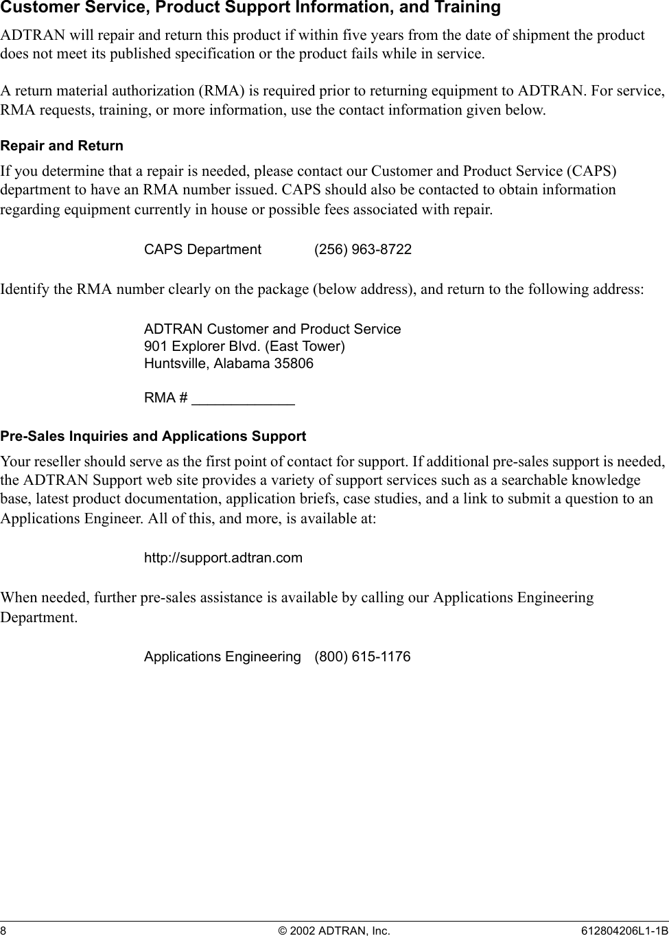

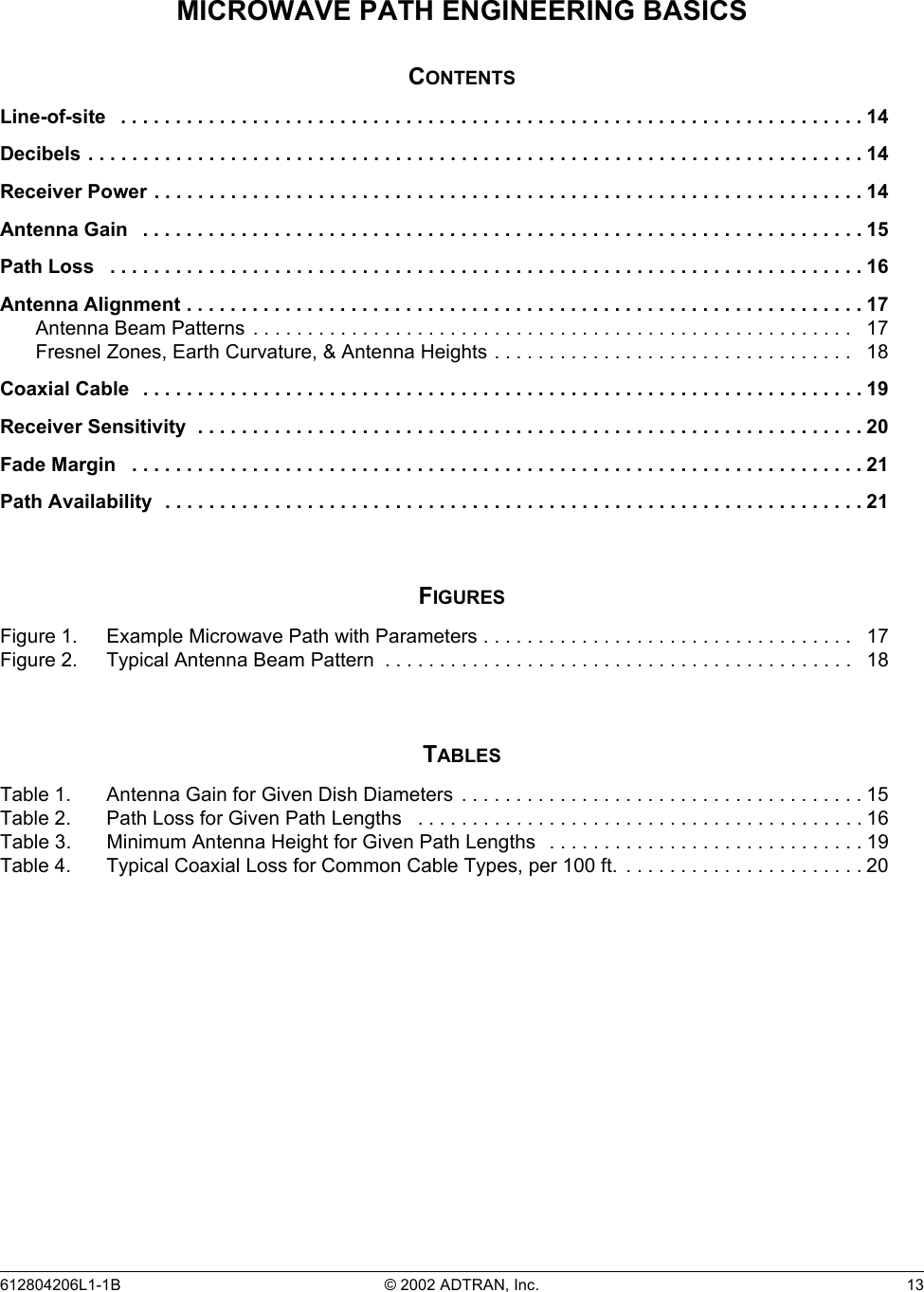
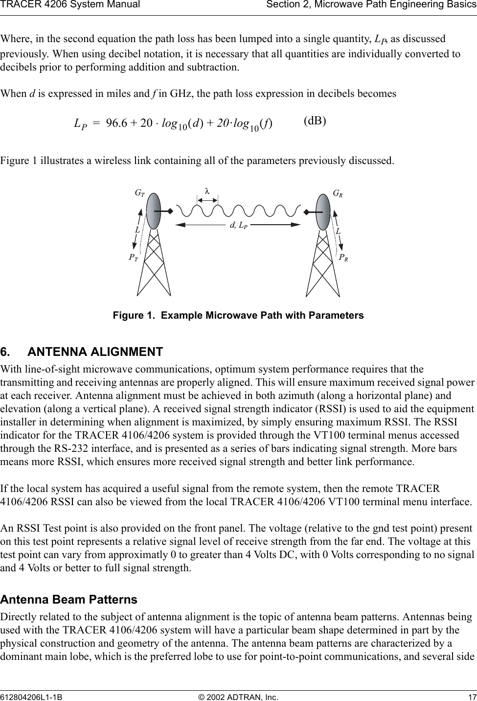
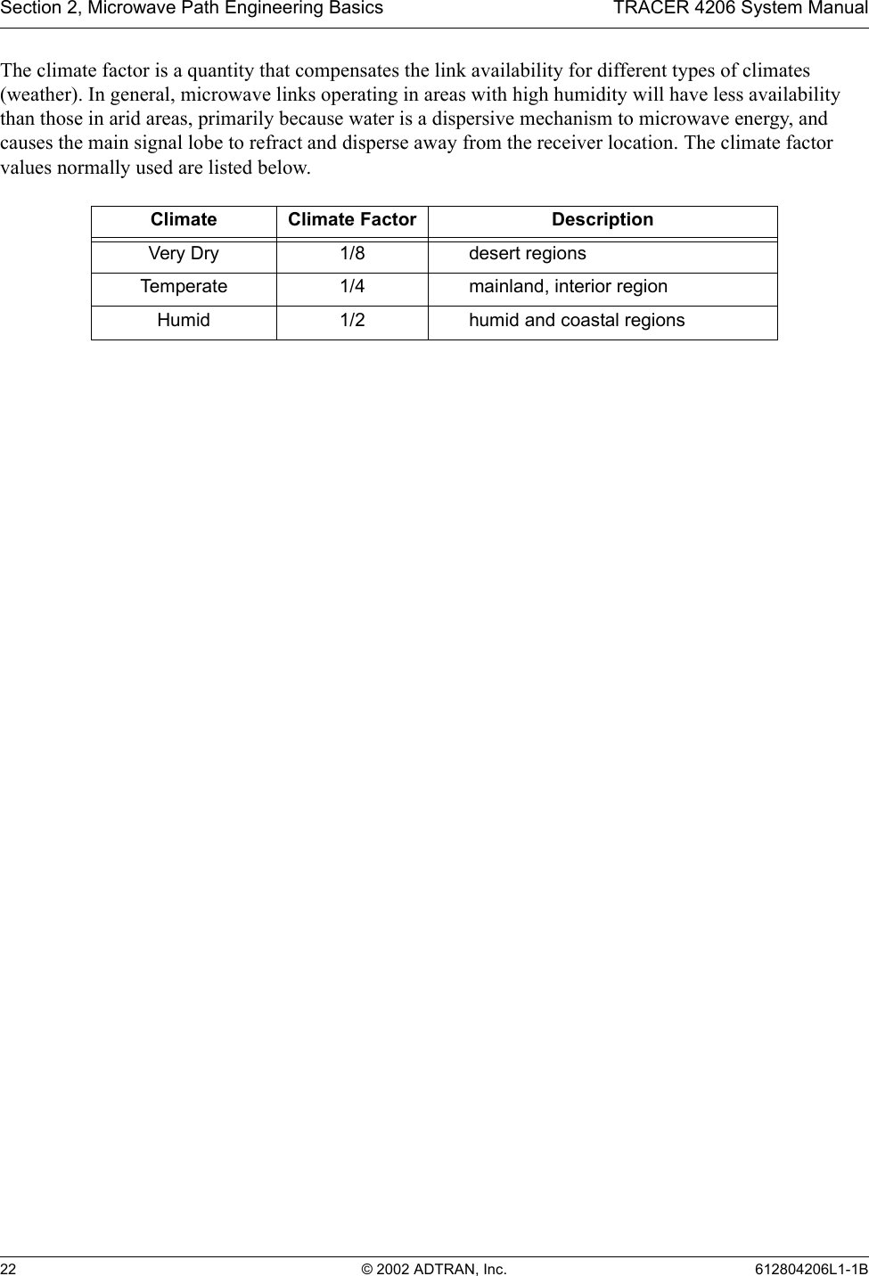
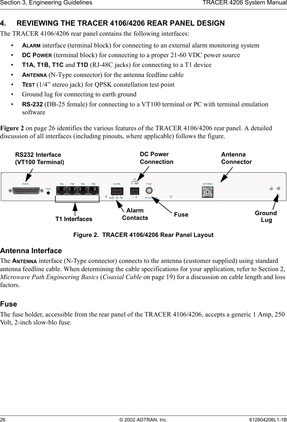
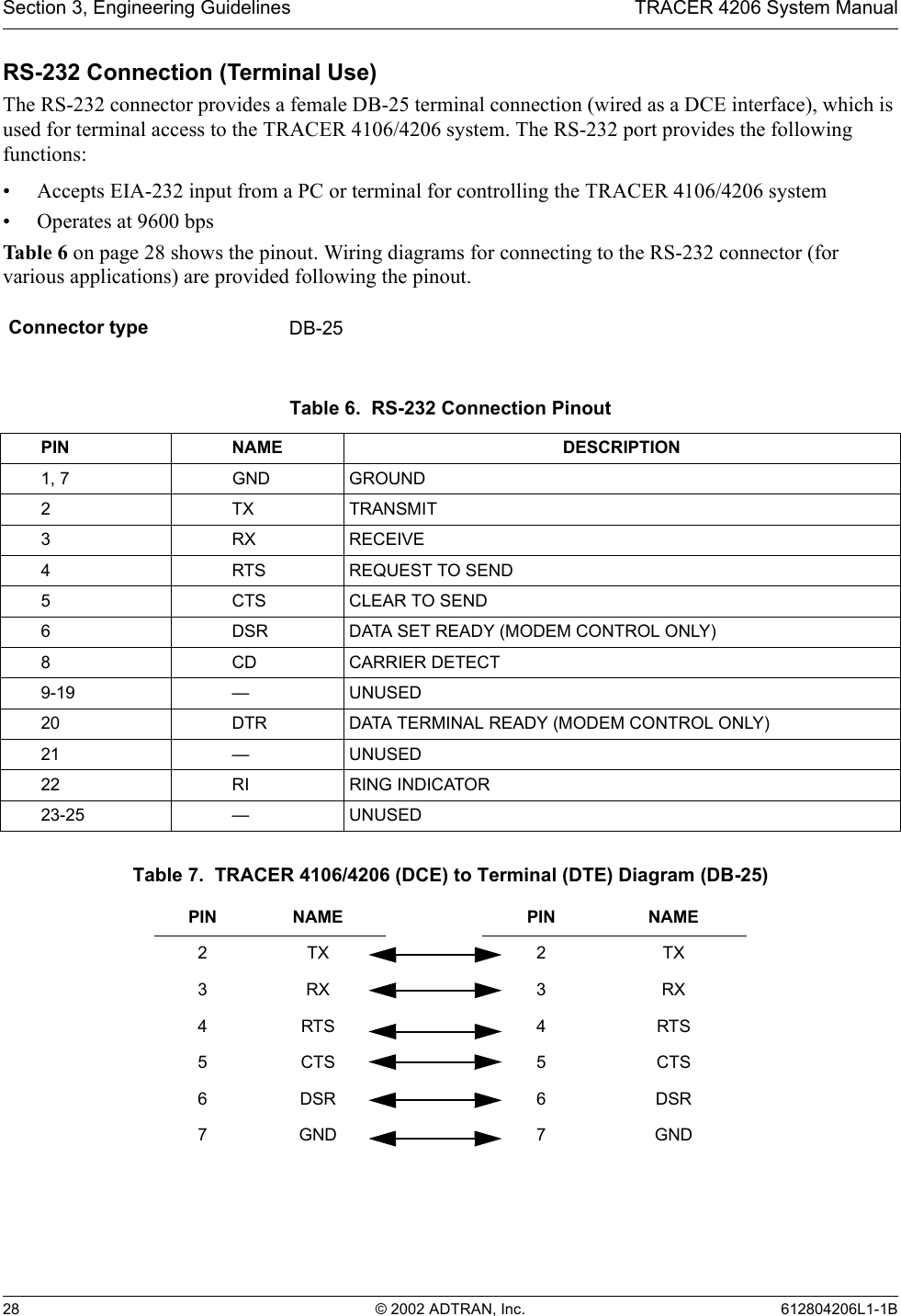
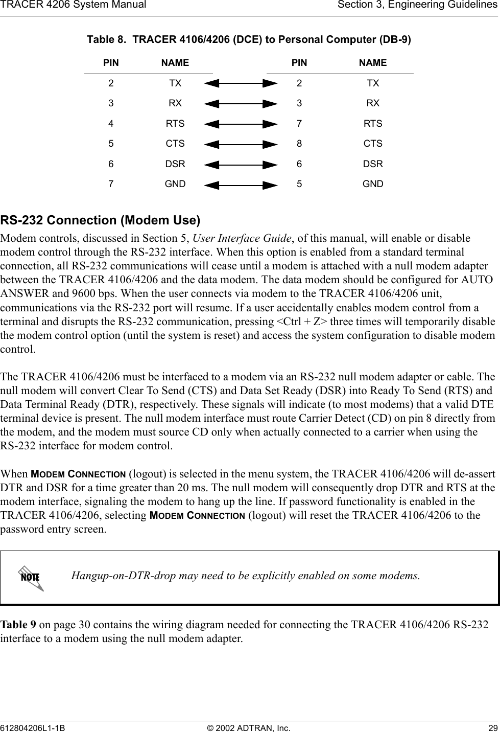
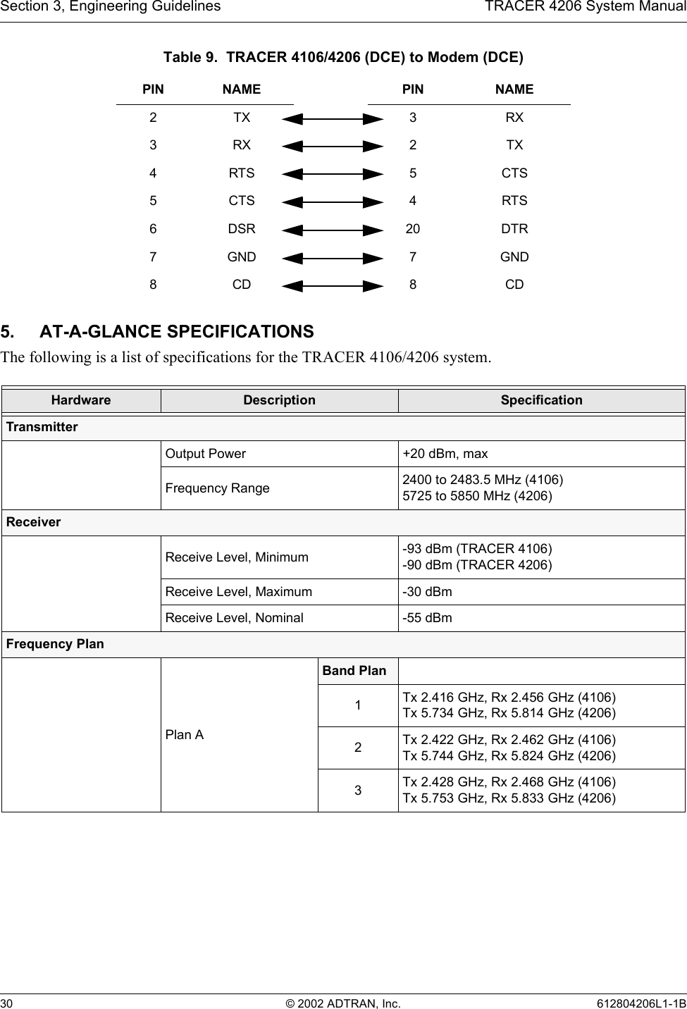
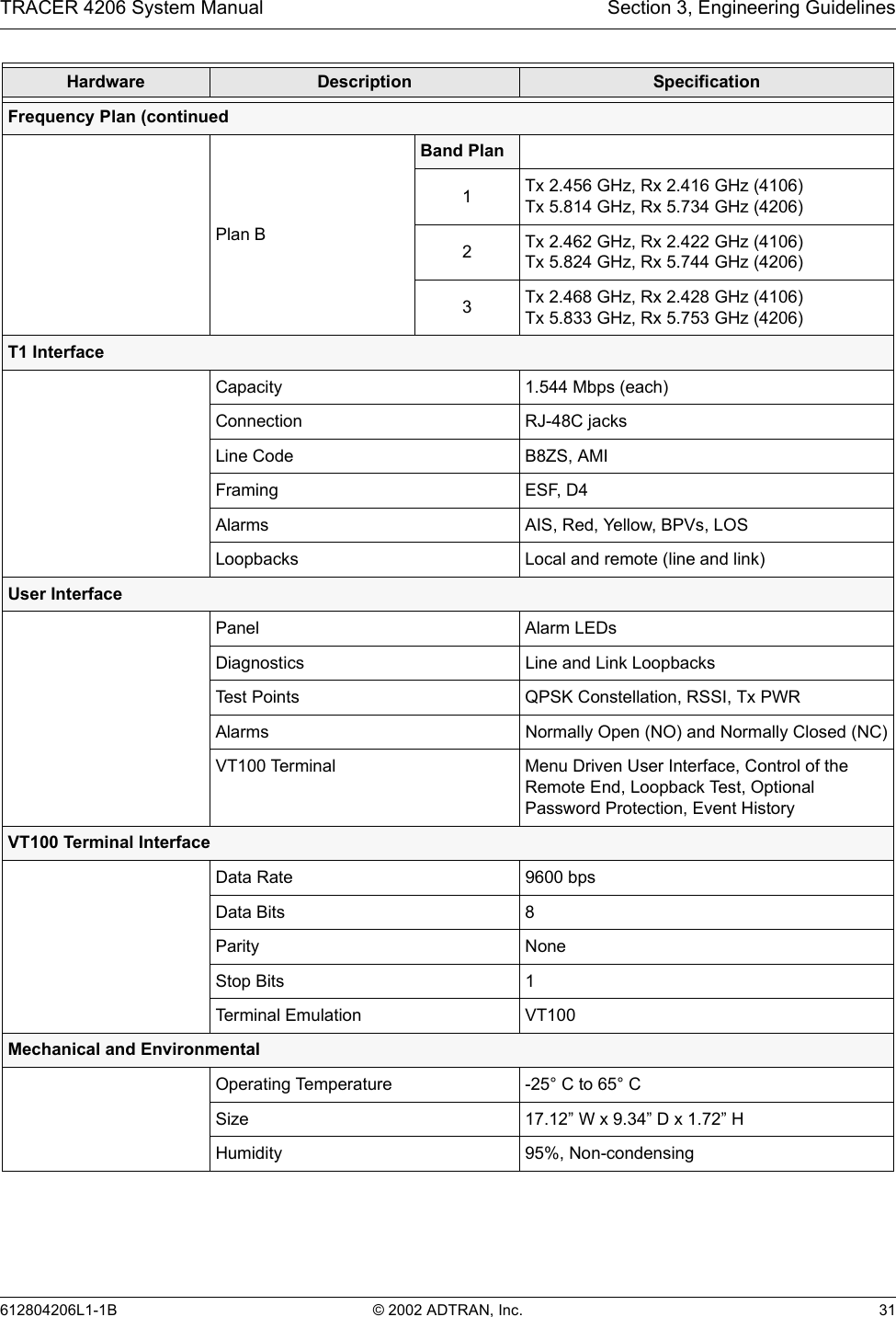
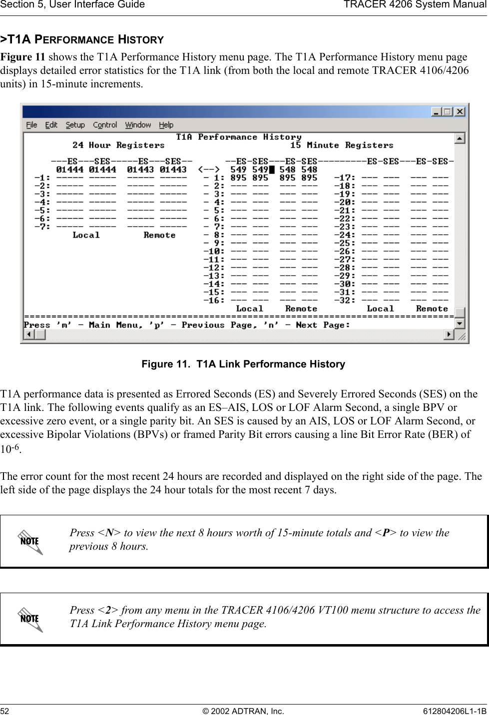
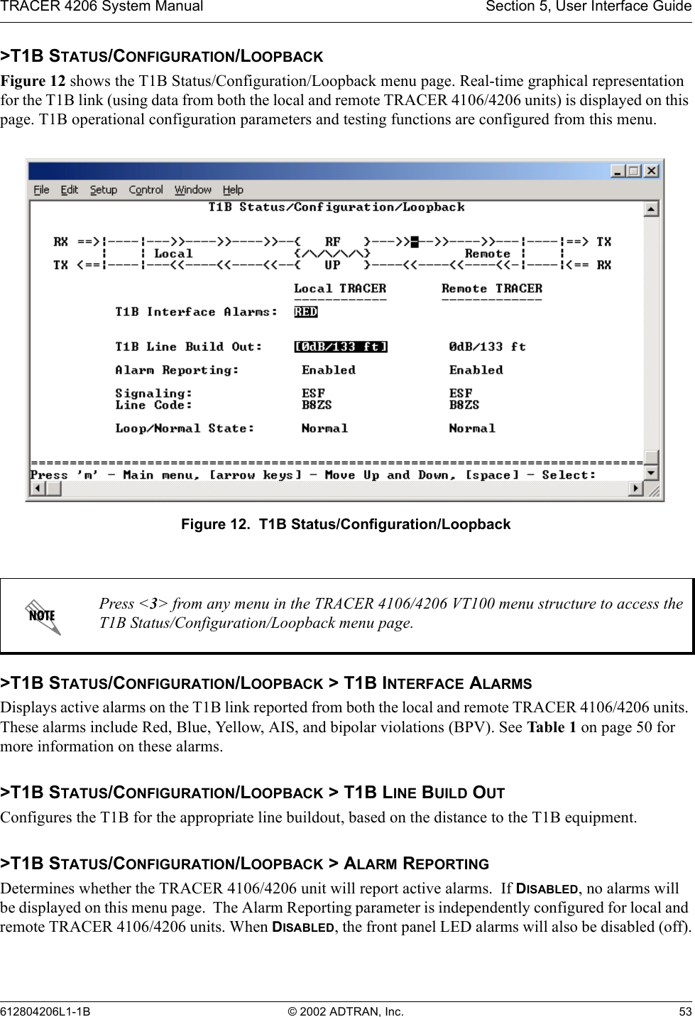
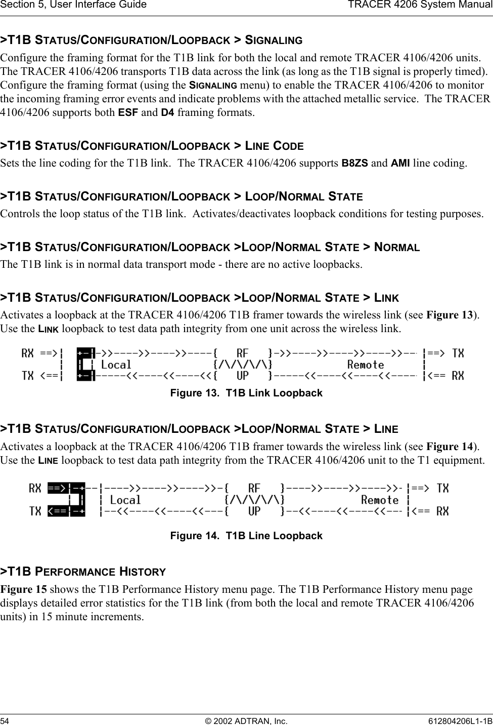
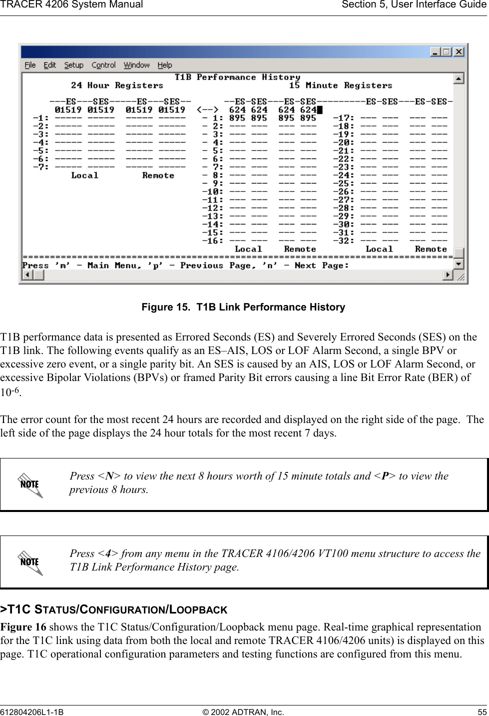
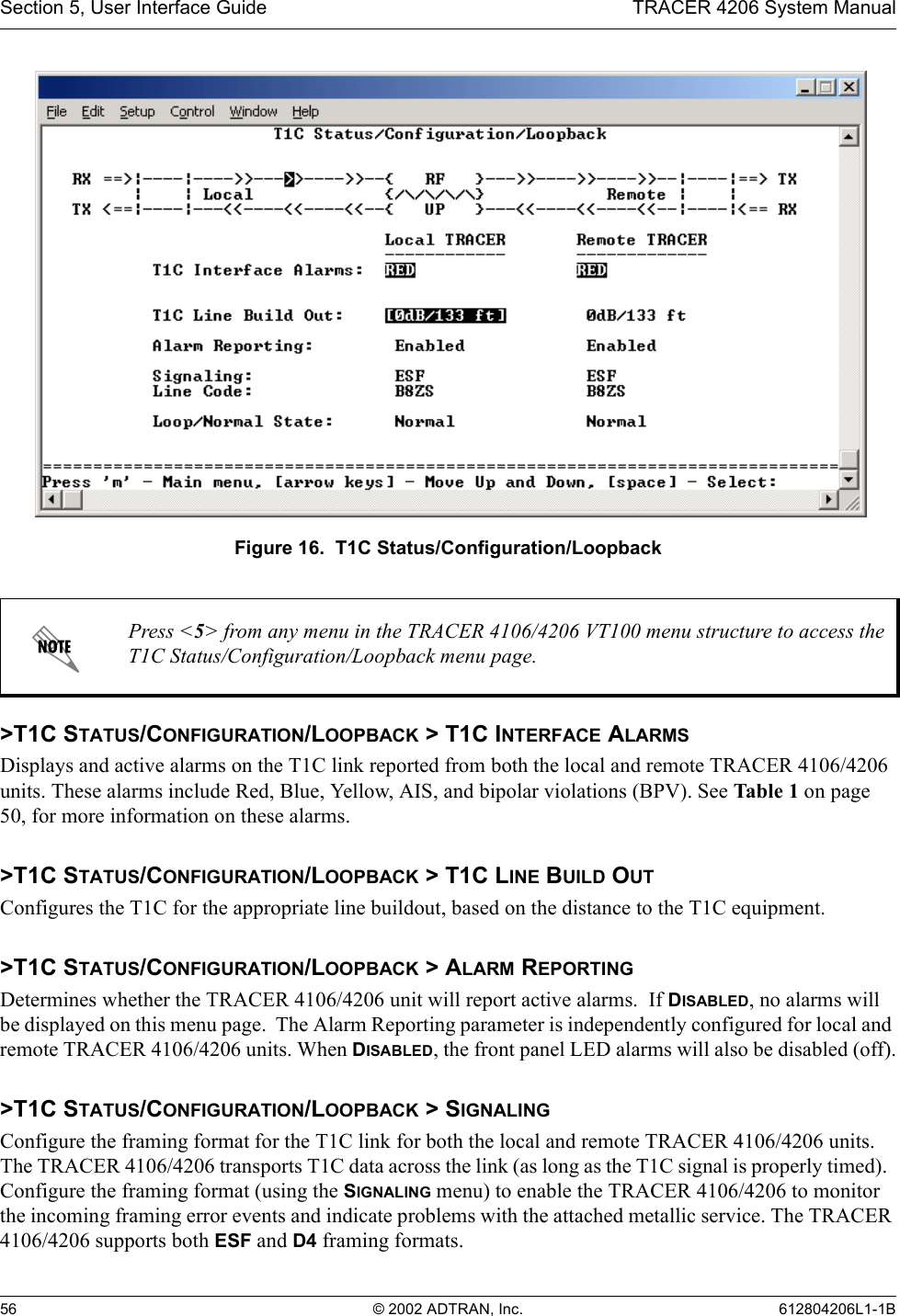
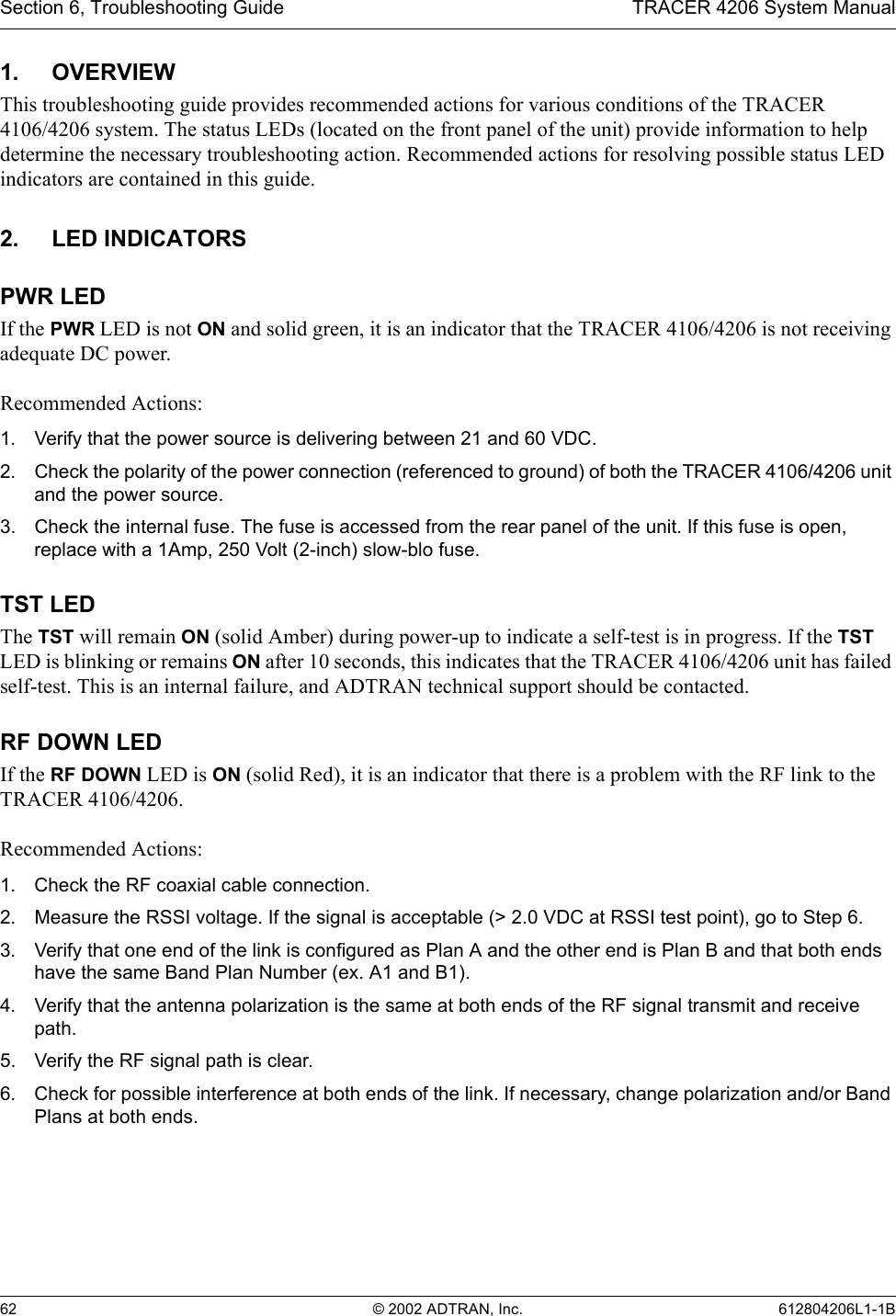
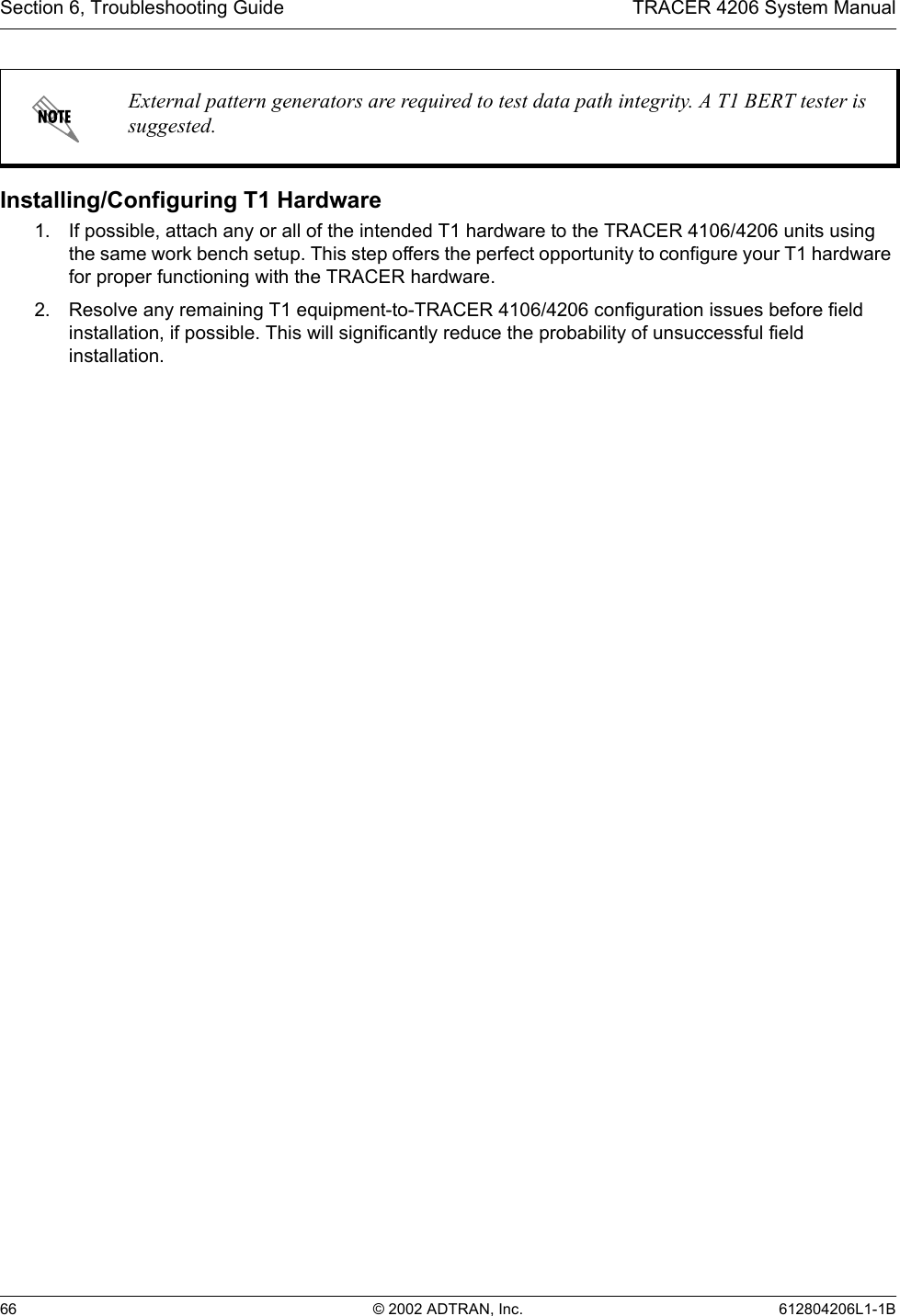
![TRACER 4206 System Manual Section 2, Microwave Path Engineering Basics612804206L1-1B © 2002 ADTRAN, Inc. 219. FADE MARGINFade margin is a value indicating the amount of extra signal power available to the receiver to operate at a maximum bit error rate (BER). Higher levels of fade margin are better, and will protect the viability of the microwave link against signal fading. For most applications, 20 to 30 dB of fade margin should ensure a reliable link. Fade margin is simply the difference between the available signal power at the receiver and the receiver sensitivity, discussed previously:10. PATH AVAILABILITYThe path availability of a wireless link is a metric that expresses the fractional amount of time a link is available over some fixed amount of time, and depends on several factors. Path availability is expressed aswhere the parameters areaterrain factorbclimate factorfcarrier frequency (GHz)dpath length (miles)Ffade margin (dB)The terrain factor is a quantity that compensates the link availability for different types of terrain. Generally speaking, the more smooth an area's terrain is, the less availability a wireless link running over that terrain will have, primarily due to multipath reflections. In contrast, secondary microwave signals will be randomly dispersed over rough terrain, and will not interfere with the main signal lobe as badly as in the smooth terrain case. The terrain factor values normally used are listed below:Terrain Terrain Factor DescriptionSmooth 4water, flat desertAverage 1moderate roughnessMountainous 1/4 very rough, mountainousFPRPsens±PRGTGRL±LP±Psens± (dB)A1 2.5 10 6±×()abfd310 F10⁄±()±[]100%× (dB)](https://usermanual.wiki/ADTRAN/TRC4106/User-Guide-308817-Page-21.png)