AEE Technology AEEAP11A001 Aerial Photography Equipment User Manual
Shenzhen AEE Technology CO., LTD. Aerial Photography Equipment
User Manual

aee.com
2
Quadcopter User Manual
V1�0 2015�8
Please read this "User Manual "carefully before using Quadcopter.
Conventions
Except when specically stated, all Quadcopter features described in this manual are for Quadcopter Operating Modes.
Warning :
(1) When installing the propellers, rotate the propellers strictly in the lock direction specied by the mark, and DO NOT apply too much force in order to avoid
possible damage�
(2) When removing the propellers, rotate the propellers strictly in the unlock direction specied by the mark, in order to avoid possible damage.
3
aee.com
3
Overview
The quadcopter is a high-tech electronic with integrated ight and camera control. When install camera, you can use mobile devices to control the camera through
the App and achieve real-time video images� The quadcopter will help you capture clear an stable aerial videos and photos�
Note:The camera operation as mentioned below, is only applied for the operation of the AEE S61.
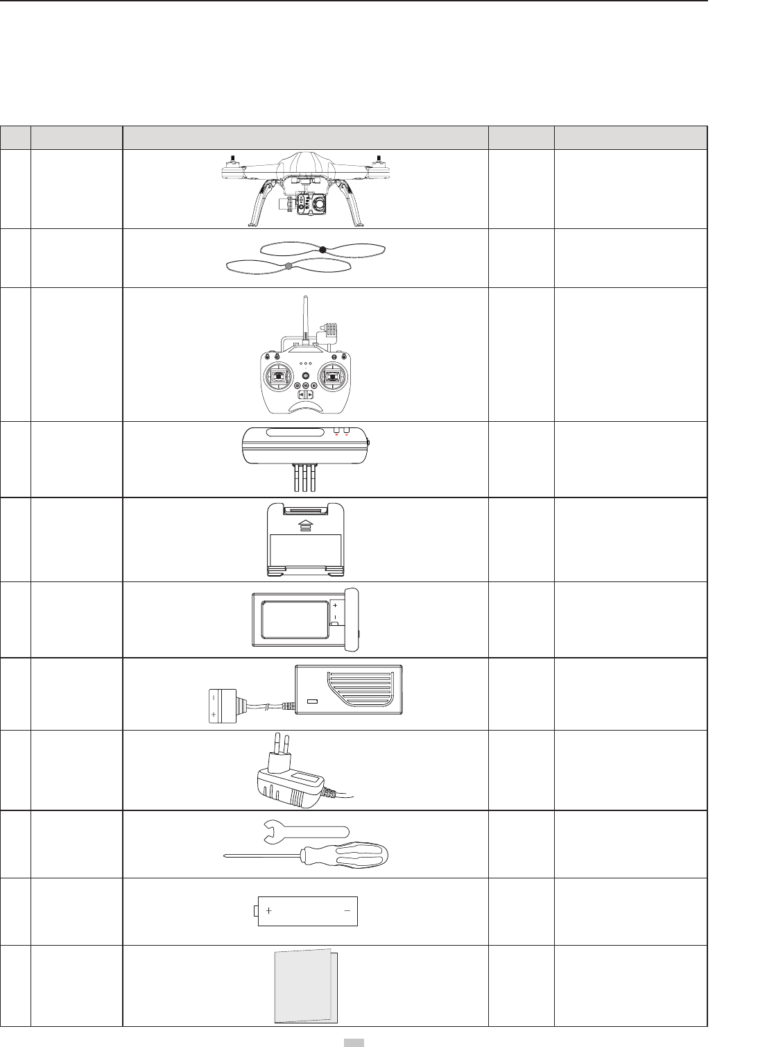
1 Kit Contents
Before using, please check all items inside the kit box.
No� Name Diagram Quantity Description
1Quadcopter 1 pcs Camera iis optional
2Propellers 4 pairs 4 pcs with black nuts;
4 pcs with gray nuts
3Remote control 1 pcs With Wi-Fi Repeater Base
(Optional)
4Wi-Fi Repeater 1 pcs For connecting mobile devices
through Wi-Fi
5Smartphone Holder 1 pcs For attaching mobile devices
6Quadcopter Battery 1 pcs Quadcopter power supply
7Quadcopter Battery
Charger 1 pcs 100-240V 50/60Hz
8Wi-Fi Repeater
Adapter 1 pcs 100-240V 50/60Hz
(Optional)
9Tools 1 set
1pcs wrench - (for
disassembling propeller )
and 1pcs screwdriver (for
assembling propeller guard)
10 AA batteries 4 pcs For Remote control power supply
11 Manuals 1 pcs Including: Quadcopter User
Manual , Quadcopter Quick
Start Guide,Disclaimer
aee.com
4
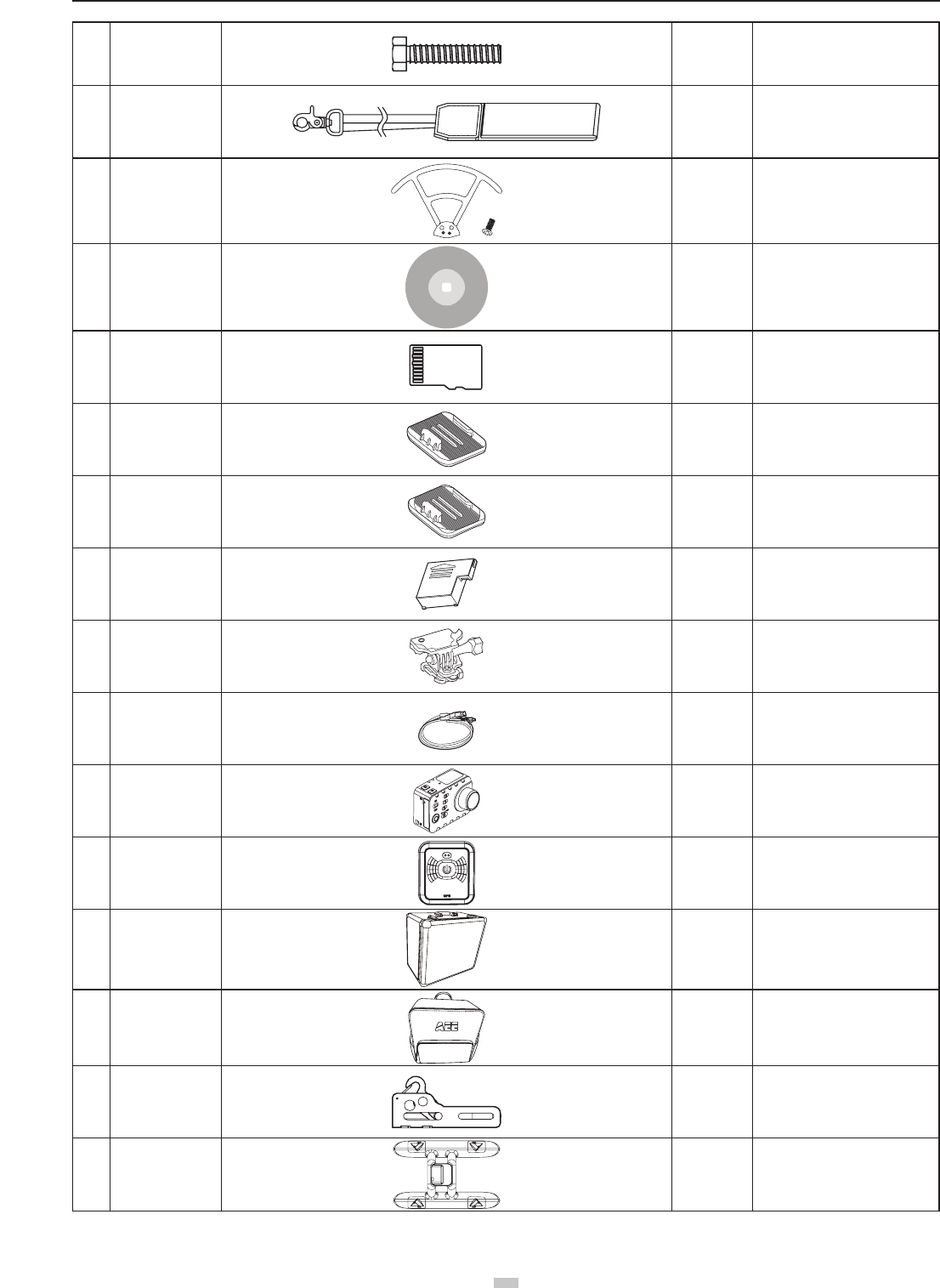
12 Screws 1 pcs For Wi-Fi Repeater
(Optional)
13 Lanyard 1 pcs Remote control Lanyard
14 Propeller Guards 1 set Including 4 Propellers Guards
and 8 screws.
15 CD 1 pcs Containing User Manual, etc..
(optional)
16 Micro SD card
1 pcs
(16GB/32GB
64GB)
Inserted in Quadcopter Micro SD
card port (optional)
17 Flat sticker 1 pcs Flat accessory
(optional)
18 Arc sticker 1 pcs Arc accessory
(optional)
19 Lithium battery 1 pcs S-series lithium battery
(optional)
20 Support assembly 1 set Support assembly
(optional)
21 USB cable 1 pcs S-series USB cable
(optional)
22 Camera 1 pcs S-series camera
(optional)
23 GT10 1 pcs
Including wrist strap and charging
cradle Q43
(optional)
24 Aluminum case 1 pcs (Optional)
25 Bag 1 pcs (Optional)
26 Hook 1 pcs It can be used to hang / airdrop
lightweight objects (optional)
27 Float 1 pcs Accessory for overwater take-off /
landing (optional)
● Accessories you have received may vary due to different product customizations. Package contents are subject to change without further notice.
5
aee.com
5
2 Quadcopter Introduction
Adopting high-standard integrated design . If it is equiped with professional airborne photography equipment and a Wi-Fi Repeater, Quadcopter provides excellent
ight and aerial photography for outdoor or large indoor spaces. You only need to follow some simple installation steps before ight and taking aerial pictures. You
can control the Quadcopter through the Remote control, and can view ight video through mobile devices. Featuring simple and exible operating procedures,
Quadcopter has stable and reliable performance, and can be used for amateur or commercial photography.
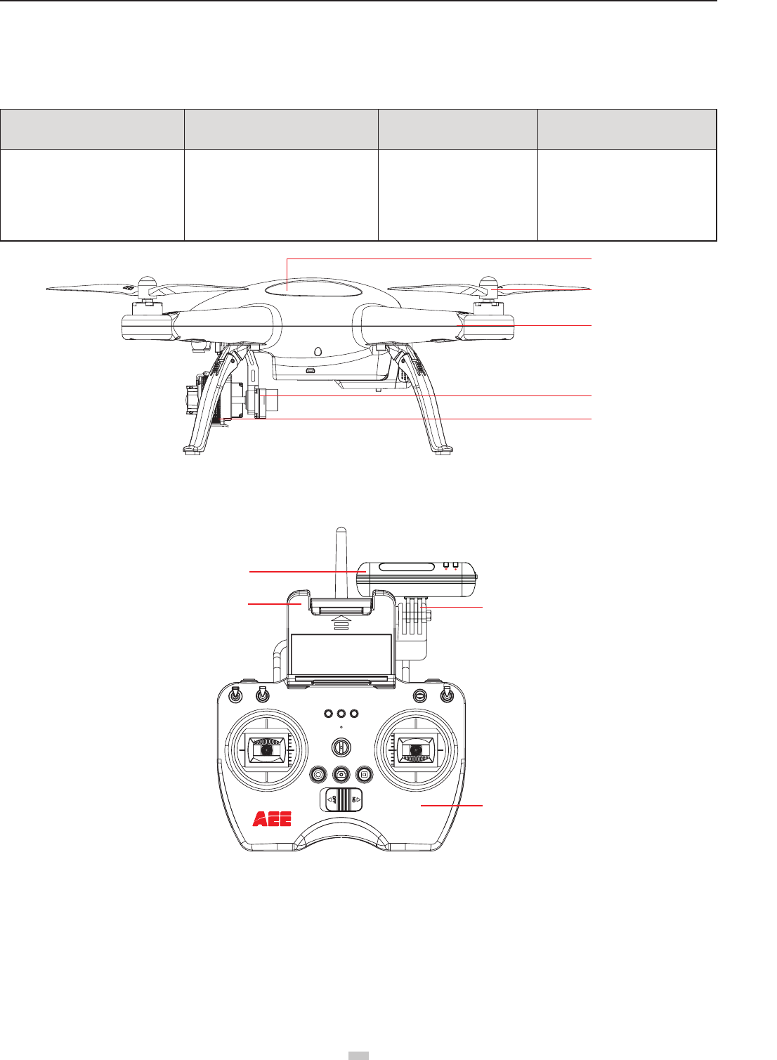
Remote control Device Quadcopter External Components Operating Modes Quadcopter Internal Components
Remote control with 2 joysticks, multi-
channel
Gimbal
Power units (motor and blades)
Camera (optional)
GPS mode
Normal mode
Follow Me mode
Flight Control System
Wi-Fi module
Receiver
ESC (Electronic Speed Control)
Quadcopter
Propellers
Motor
3-Axials Gimbal
Camera
Figure 1
Repeater Base
Remote control
Wi-Fi Repeater
Smartphone Holder
Figure 2
Preparations before ight
Refer to the following for installing components and pre-ight quadcopter check.
1 Preparing Batteries
Ensure all device batteries are fully charged before operating Quadcopter�
aee.com
6
Device Power Supply
Remote control Load 4 AA batteries for power supply
Wi-Fi Repeater Wi-Fi Repeater should be charged through the inbuilt charging port (Mini USB port)
Quadcopter Charge quadcopter batteries for power supply
Mobile devices Please ensure that your mobile device is fully charged before using App
The following instructions are for the quadcopter battery�
1.1 Quadcopter Battery Introduction
The quadcopter battery (Figure 3) is a specically designed battery for Quadcopter with charge and discharge management functions, with voltage of 11.1V. Only
use the dedicated quadcopter battery charger (Figure 4) provided by AEE, for charging.
Figure 3 Figure 4
Short press the Battery Level Check button (Figure 5)� Battery Level LCD Segment Display displays appropriate battery level� Please fully charge the battery if it is
less than two bars�
Battery Level
Check button
Battery Level
(Segment Display)
Figure 5
Battery Specications
Type Li-Po Battery
Charging ambient temperature 0°C-50°C / 32~122°F
Discharging ambient temperature -20°C-50°C / -4~122°F
Charge / discharge ambient relative humidity < 80%
Please carefully read and strictly comply with this manual before use� Users take full responsibility for any problems caused due to failure to follow instructions�
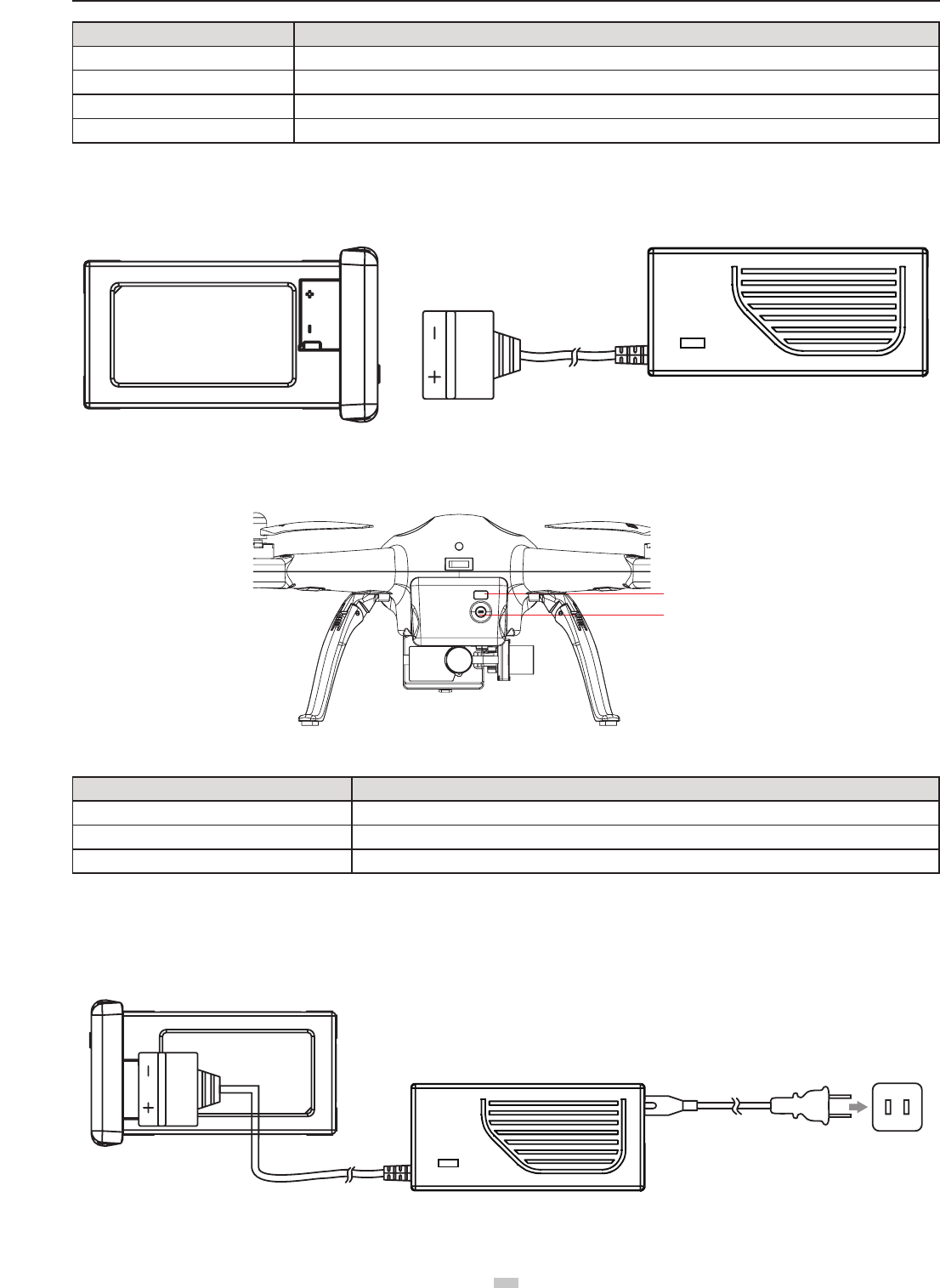
1.2 Charging the Quadcopter battery
(1) Connect the charger to an AC power source (100-240V, 50 / 60Hz). Please use a power adapter, if necessary.
(2) While charging, the battery charger indicator turns red.
(3) When the battery charger indicator turns green, the battery is fully charged. Disconnect the charger and battery when charging is complete.
Figure 6
7
aee.com
7
1.3 Quadcopter Battery Installation
Push the battery into the battery compartment in the correct direction (Figure 7). After the battery is properly installed, a “click” sound will be heard, indicating that the
battery has been fastened�
Figure 7
1.4 Caution
(1) Do not directly pull out the battery when the Quadcopter is switched on as it may damage the power supply connector�
(2) For long term storage, discharge the battery to 40%-50% power, and store in a specied battery box. Discharge/charge the battery once every three months to
maintain battery life�
(3) Replace the battery after it has been discharged over 300 times� Completely discharge a battery prior to disposal�
(4) Replace the battery if your current battery swells up or is damaged in any way, to avoid re and explosion.
(5) Do not charge expanded or damaged batteries�
(6) Please pay attention to the battery charging process in order to avoid accidents, and make sure there are no ammable or combustible materials around the
battery and the charger�
(7) Battery safety is extremely important� Please refer to Disclaimer for more precautions�
2 Preparing the Quadcopter
The Quadcopter consists mainly of the ight control system, gimbal, camera (optional) and power unit.
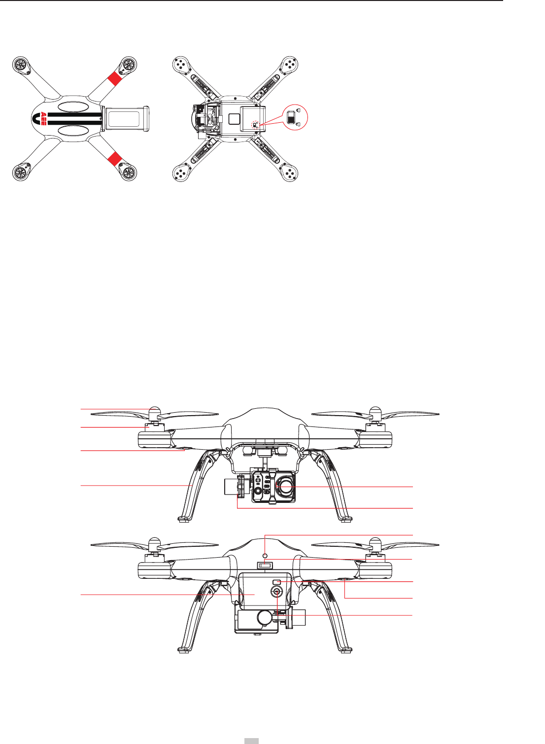
2.1 Introduction
[ 1 ]
[ 2 ]
[ 3 ]
[ 4 ]
[ 7 ]
[ 5 ]
[ 6 ]
[ 8 ]
[ 9 ]
[11]
[10]
[12]
Figure 8
[ 1 ] Propeller [ 2 ] Motor [ 3 ] Front Indicator [ 4 ] Landing Gear
[ 5 ] Camera [ 6 ] 3-Axials Gimbal [ 7 ] Quadcopter Battery [ 8 ] Tail Indicator
[ 9 ] Power Switch [ 10 ] Rear Indicator [ 11 ] Battery Level LCD Segment Display
[ 12 ] Battery Level Check Button
An incorrectly installed battery may
cause
● Bad contact
● Affect ight safety
● Inability to take off.
aee.com
8
2.2 Flight Control System
Quadcopter is equipped with AEE ight control system to provide incredible ease of use and stability. In addition to supporting basic ight maneuvers such as climb,
descend, roll and pitch, it also supports failsafe protection, battery level alarms and other functions.
System Component Modules Function
Master Controller The core part of the ight control system controls all modules in a centralized way
GPS & Compass Used for positioning and navigation
Indicator Indicates current ight control system status. Used to navigate during night ight
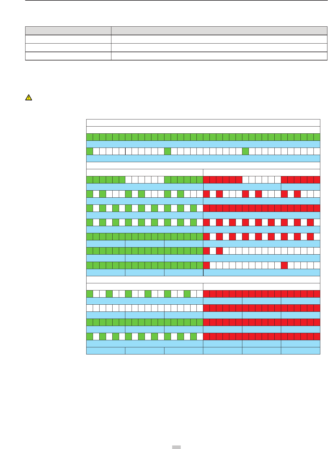
2.3 Flight Indicator
Flight indicators include the forearm indicator, rear arm indicator and tail indicator. When the Quadcopter is powered on, the ight indicators will be turned on –
forearm indicator in green (“green indicator”) and rear arm indicator in red (“red indicator”).
WARNING:Do not power on the quadcopter before aseembly camera and remove the gimbal buckle,in order to avoid possible damage.
Quadcopter LED Flight Indicators
MODE
Tail Indicator (green)
WARNING & ERROR
MODE
GPS normal
Searching GPS signal
WARNING & ERROR
1 Level low battery alarm
2 level low battery alarm
Compass abnormal
Accelerometer abnormal
Gyro abnormal
GPS Module abnormal
Barometer abnormal
Compass calibration entered
Compass calibration started
Compass calibration Successful
Compass calibration Failed
st
nd
COMPASS CALIBRATION INDICATOR
Front Indicator (green)
ON-Blinking-ON-Blinking
Blinking fast (blinking 3 times within 1s)
Blinking fast (blinking 3 times within 1s)
Remains ON
Slow Blink(1s ON,1s OFF)
Blinking fast (blinking twice fast within 1s) Blinking fast (blinking twice fast within 1s)
Slow Blink (1s ON,1s OFF)
Rear Indicator (red)
Front Indicator (green) Rear Indicator (red)
Remains ON
Remains ON
Remains ON
Remains ON
1second1second 1second 1second 1second 1second
Remains ON
Remains ON
Remains ON
Blinking fast (blinking 3 times within 1s)
Blinking fast (blinking 3 times within 1s)
Blinking fast (blinking twice within 3s)
Blinking slowly (blinking once within 2s)
Blinking slowly (blinking once within 2s)
Blinking fast (blinking twice within 1s)
Blinking fast (blinking 3 times within 1s)
OFF
Remains ON
Remains ON
● When abnormal status occurs, please refer to the solutions of Common Troubleshooting.
2.4 Remove the Buckle and Install the Camera
Two types of cameras can be installed onto the quadcopter Quadcopter:
1� AEE S50/S51/S60/S61/S71/S70/OM51S/OM60S/OR60S/OR71S/S40; or
2� Gopro G3/G4�
Note:The App mentioned in this paper applies only to the AEE S61 camera mounted on the quadcopter. When using other cameras, it is required to use the other
APP for the camera itself�
9
aee.com
9
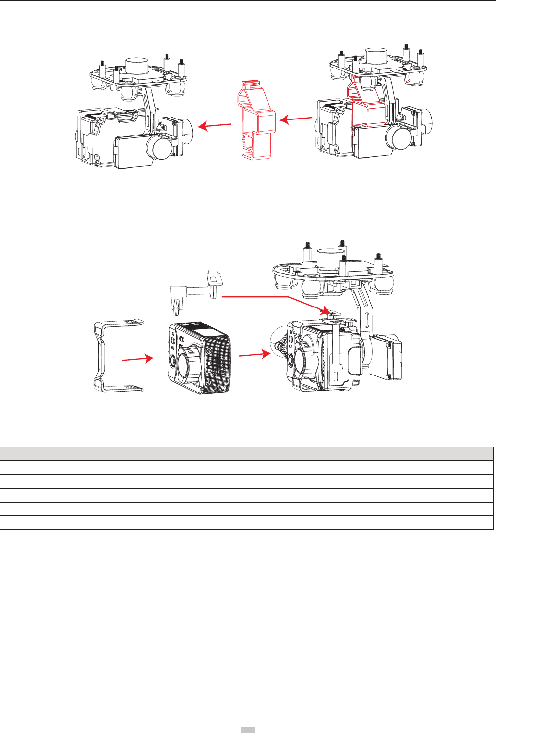
2.4.1 Remove the Buckle:
Pull out the buckle of the gimbal in the direction shown in Fig� 9a:
Figure 9a
2.4.2 Install the Camera:
Install the camera onto the quadcopter and x the clip to the camera reliably as shown in Fig. 9b to prevent the camera coming off.Then connect camera and the
gimbal with USB cable (only for AEE S61)�
Diagram of installation of PTZ USB cable
Figure 9b
2.5 Airborne Camera
With S61 camera installed on the quadcopter, You can take photos and record videos with the camera function button. Camera also can be set by App. The camera
supports Single Shot and Fast Shot, with video capture resolution up to 1080P / 60fps (N system) 1080P / 50fps (P system) Full HD video.
Camera Specications
Resolution Maximum 1080P / 60fps (N system) ,1080P / 50fps (P system), 720P/120fps
Image Resolution 4608x3456
Video Formats MP4 (H�264)
Storage External Micro SD card, up to 64GB
TV system P / N system optional
Do not handle the camera manually at any time (only use the remote control to control it), or the camera could be damaged.
2.5.1 Camera Function Buttons
Photo shooting: Press the airborne photo shooting button on the remote control once to take once photo (the APP button can also be used to take photos)�
Video-recording: Press the airborne video recording button on the remote control or the APP interface to control the airborne camera to start video recording�
Press the stop video recording button on the remote control or the APP interface to stop video recording�
2.5.2 Copying Camera Data
Power off Quadcopter before removing the Micro SD card from the card port, and connect it to a computer with a card reader to easily copy camera les. (Quadcopter
and Camera power must be OFF while removing the Micro SD card)�
2.5.3 Shooting Status Indicator
After startup of the quadcopter, the user can judge the current status of the quadcopter according to the status indicator. The status indicator is on the remote control,
as shown in Figure 11, the three indicators from left to right are power indicator (red), status indicator (tri-color: red/green/blue), and Photo shooting & video recording
indicator (green)�
aee.com
10
Figure 11
Indicators on the remote control
Power indicator Status indicator(tri-color light) Photo shooting & video
recording indicator
Red light ●Red light ● /green light ● /blue
light ●Green light ●Function status
Remaining ON N/A N/A Power on
Remaining ON Red light remains ON N/A Abnormal condition, as signal loss etc.
Remaining ON Blue light remains ON N/A Indicates that signal connection is normal and the quadcopter is in the GPS
signal searching status�
Remaining ON Green light remains ON N/A Indicates that signal connection is normal and GPS signal is good
Remaining ON Blue light blinks N/A
Indicates that the quadcopter is in the GPS signal searching status and in the
auto ight mode (low-battery auto landing); now the remote control can regain
control of the quadcopter via the S4 switch�
Remaining ON Green light blinks N/A
The rst situation indicates that the GPS signal is good and the quadcopter is in
the auto y mode (1. auto landing, or 2. low-battery auto landing); now the remote
control can regain control of the quadcopter via the S4 switch�
The second situation indicates the joystick calibration status. During calibrating,
the indicator blinks. When the green light will go out, the calibration completes
successfully. If the calibration does not complete, the green indicator will continue
blinking�
Remaining ON N/A Blinks once Blinking once during Capture: once photo is taken (only to the AEE S61 camera
mounted on the quadcopter)�
Remaining ON N/A Blinking Slowly The camera is recording
1) When Remote control battery power is low, a warning alert sounds (di didi di didi…).
2 ) When the remote control or the APP sends a command for video recording, the video recording indicator on the remote control will blink.
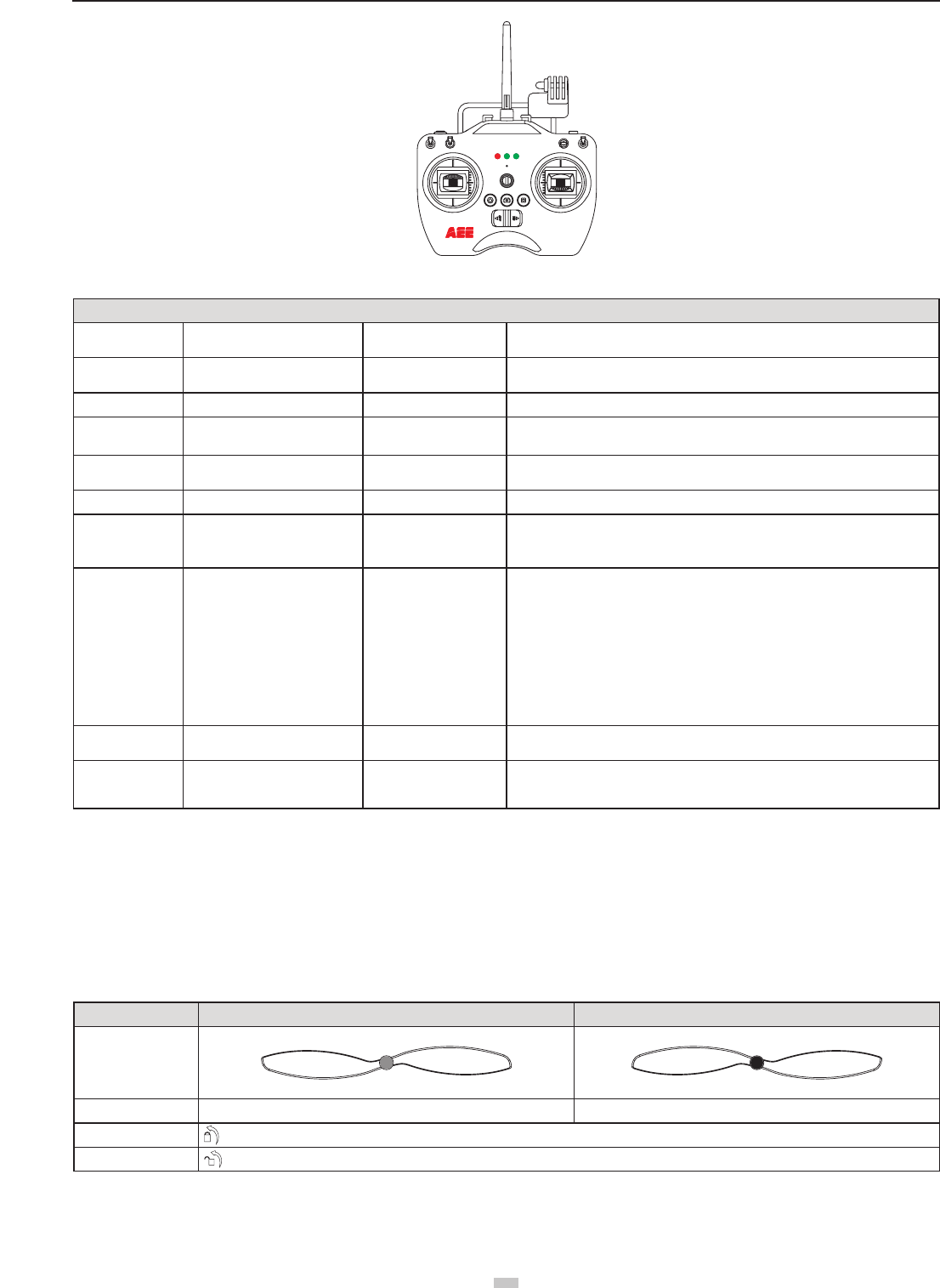
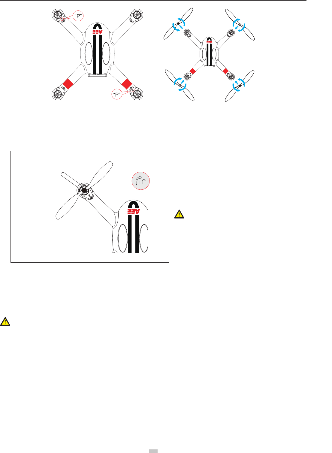
3 Preparing Propellers
uadcopter adopts 10-inch propellers, with black and gray color propeller nuts. Propellers are consumable items. Please purchase these accessories separately, if
necessary�
3.1 Introduction
Propellers Gray (1045) Black (1045 P)
Diagram
Assembly Location Attach to the motor shaft without "P" mark Attach to the motor shaft with "P" mark
Installation Location Lockup: Tighten propeller in this direction
Symbol Description Unlock: Loosen propeller in this direction
3.2 Assembling Propellers
(As shown below) Prepare two propellers with gray nuts and two with black nuts. Attach propellers with gray nuts to motor shafts without "P" marks, and attach
propellers with black nuts to motor shafts with "P" marks� Tighten propellers as per the appropriate locking direction�
11
aee.com
11
Figure 12
(1) Propellers are designed to self-tighten during ight; therefore do not tighten them excessively. Do not use glue on the threads.
(2) Ensure propellers are attached in the correct position. The quadcopter cannot y properly if the propellers are installed incorrectly. Wear protective gloves while
installing as propellers are very thin and may cause accidental scratches�
3.3 Disassembling Propellers
Auxiliary wrench
Figure 13
Unlock direction
3.4 Precautions
(1) Check whether propellers and motors are installed correctly and rmly before every ight.
(2) Ensure that all propellers are in good condition before each ight. Replace aged, chipped or broken propellers.
(3) To avoid injury, stand clear of and do not touch propellers or motors when they are spinning.
(4) Only use original AEE propellers for a better and safer ight experience.
Warning :
(1) When installing the propellers, rotate the propellers strictly in the lock direction specied by the mark, and DO NOT apply too much force in order to avoid
possible damage�
(2) When removing the propellers, rotate the propellers strictly in the unlock direction specied by the mark, in order to avoid possible damage.
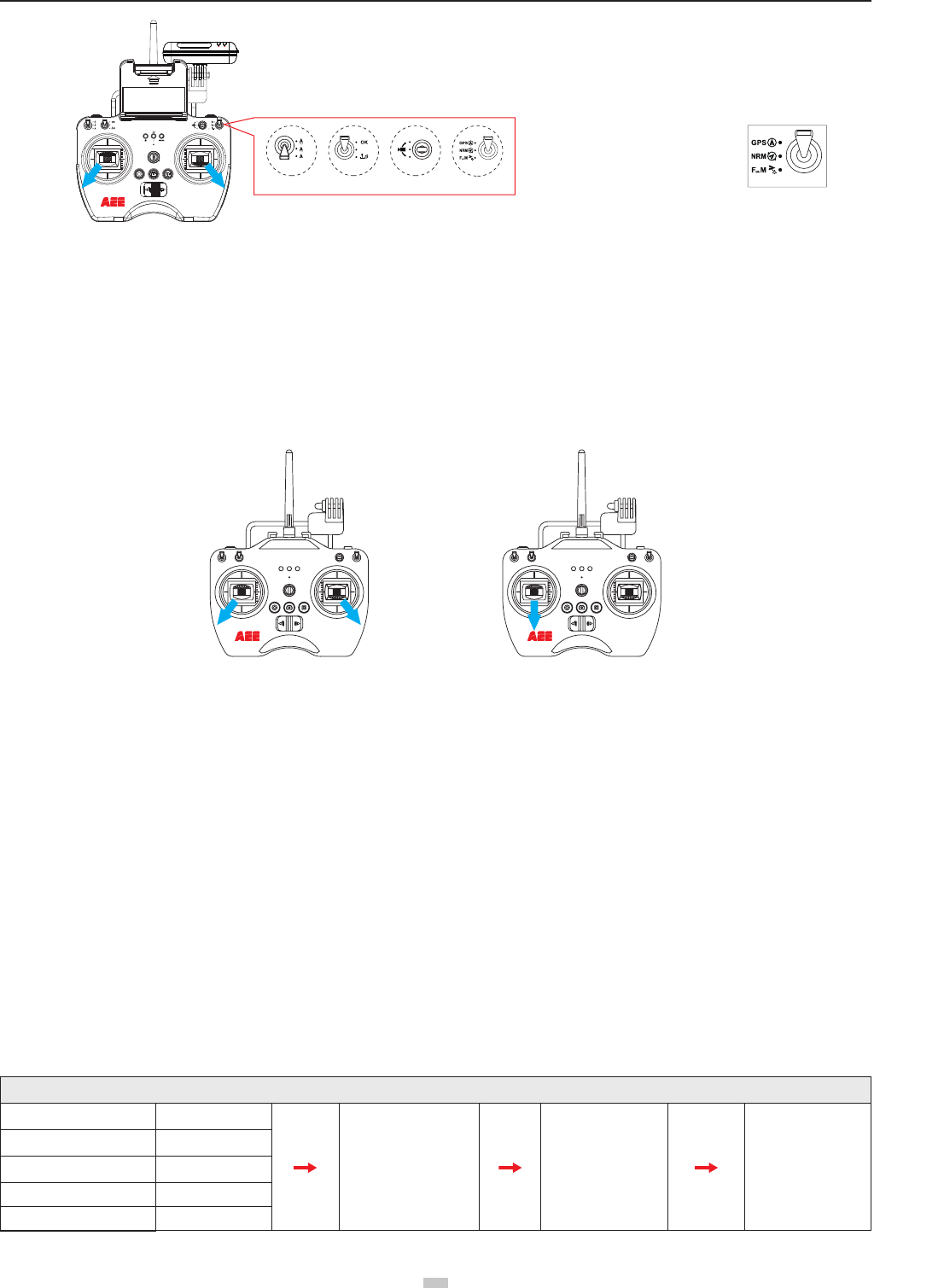
4 Preparing the Remote control
Quadcopter Remote control is paired with the Quadcopter receiver before delivery� The Remote control is set to U�S� mode by default�
- Control Mode: The Remote control is set to U�S� mode or Japanese mode based on joystick channel mapping�
- U�S� mode: The left joystick controls throttle�
- Japan mode: The right joystick controls throttle�
● Repeater mount is already installed on the Remote control before delivery. Please install the Smartphone Holder before installing a mobile device on the Remote
control�
● Over sized mobile devices (such as iPad) are not recommended as they cannot be installed on the holder.
4.1 Introduction
As shown as in the Figure 13, prevent motor
rotation by using the auxiliary wrench or your hand, then
remove propeller by turning towards the unlock direction�
aee.com
12
GPS
NRM
S1 S2 S3 S4
GPS
NRM
D
F M
S
E
NULL
[ 22 ]
[ 21 ]
[ 20 ]
[ 17 ]
[ 13 ]
[ 10 ]
[ 9 ]
[ 6 ]
[ 2 ]
[ 5 ]
[ 15 ]
[ 1 ]
[ 3 ]
[ 8 ]
[ 7 ]
[ 4 ]
[
11 ]
[ 12
]
[ 14
]
[ 16
]
[ 18
]
[ 19
]
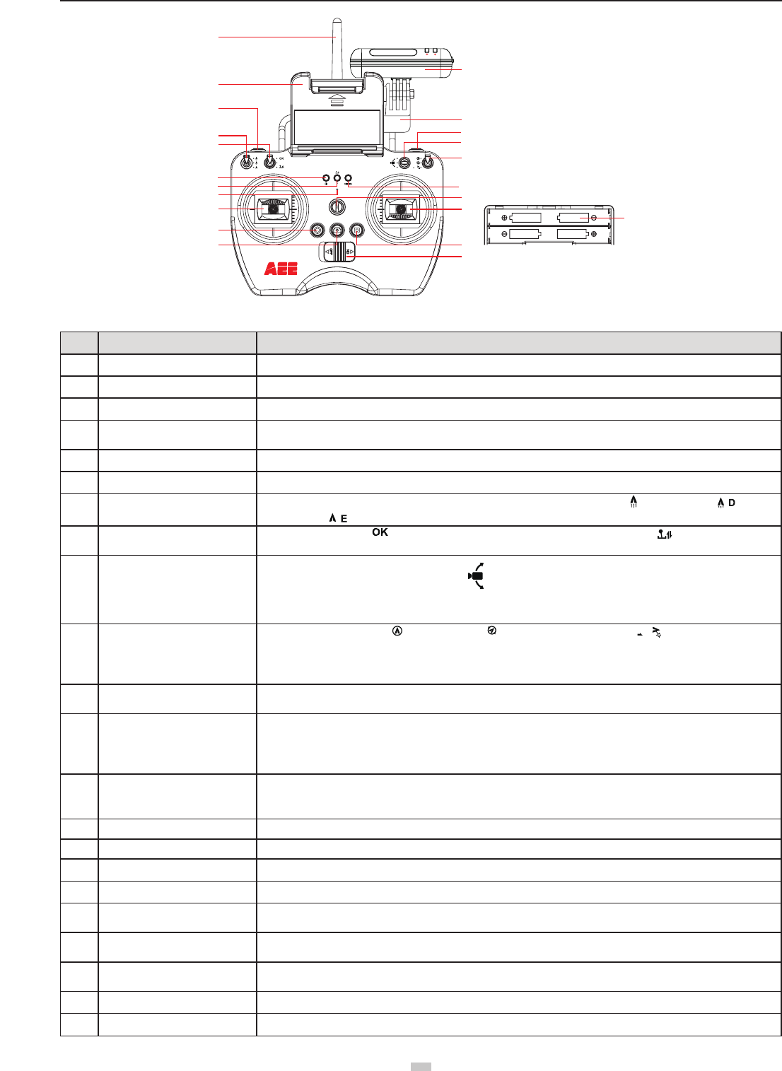
Figure 14
No. Description Specification Definition
1 Antenna Remote control signal transmission
2 Repeater For extending Wi-Fi signal reception range
3 Mobile device holder For attaching mobile devices
4 Hook open/close button Short press it once to open the hook on the quadcopter; press it again to close the hook (Remark: The hook is an
optional accessory)
5 Repeater base It is used to fix the repeater
6 Return button Long press it for 3s to send a go-home command to the quadcopter
7 Speed switch S1 There are three speed modes; the speed decreases from up to down: 1. Sport mode
S
; 2. Drive mode ;3.
Economic mode ;
8Calibration switch S2 It is a 3-channel switch. 1. (joystick calibration is OK); 2. NULL(Reserved function); 3. (start the joystick
calibration procedure)
9 Gimbal control switch S3
Diagram of PTZ motion control switch positions
Lens turns upward (upper position)
Lens stops (middle position)
Lens turns downward (lower position)
When it is turned upward/downward, the lens direction changes slowly till the allowable maximum angle is reached
10 Flight mode switch S4
It is a 3-channel switch. 1.
GPS
: GPS mode; 2.
NRM
: NRM mode (normal mode); 3
F M
: Following mode
Remark: When the quadcopter is in the auto fly mode (auto return, low-battery auto landing), at the time when the
remote control signal is restored, switch between the GPS and NRM modes twice to end the auto fly mode and now
the remote control can regain control of the quadcopter
11 Remote control power indicator Red, indicating the remote control power ON/OFF status (red light remains on when the power is turned on, and blinks
slowly in low-battery status)
12 Status indicator
Tri-color indicator
It can indicate the GPS signal status and flight mode of the quadcopter, and also the joystick calibration status.
Remark: For the sake of safety, the quadcopter should be turned off before joystick calibration
13 Photo shooting & video recording
indicator
Green light blinks slowly:Video recording.
Blinks once:When one photo is taken (single shot by Remote Control).
Green light remaining on: Indicates Remote Control starting up successfully.
14 Buzzer hole Warning tone
15 Strap hole Used to hang the remote control
16 Left joystick 2 channels;"up-down" channel controls gas, "left-right" channel controls yaw.
17 Right joystick 2 channels;"up-down" channel controls roll, "left-right" channel controls pitch
18 Airborne video recording button Short press it to send command to the quadcopter to start video recording(only to the AEE S61 camera mounted on
the quadcopter)
19 Airborne photo shooting button Short press it to send command to the quadcopter to take a photo(only to the AEE S61 camera mounted on the
quadcopter)
20 Video recording stop button Short press it to send command to the quadcopter to stop video recording(only to the AEE S61 camera mounted on the
quadcopter)
21 Remote control power switch Slide it to the left position to power OFF the remote control; slide it to the right position to power ON the remote control
22 Battery compartment It is where the battery is installed
13
aee.com
13
4.2 Powering on the Remote control
(1) Load four AA batteries into the battery compartment� Pay attention to positive and negative directions�
(2) Set S1 and S2 switches to the upper-most position and place both joysticks at the mid-point�
(3) Toggle power switch to ON position, to switch on the Remote control.
(4) The power indicator remains ON in red color after the Remote control is powered on.
● Ensure batteries of Remote Control have been fully charged before each use. If there is low voltage, the Remote control will prompt low power warning ( di didi
di didi��� )Please replace batteries immediately�
● Be sure to remove batteries from remote control in case of long-term storage.
● Remove depleted batteries and follow battery instructions for disposal or recycling.
Warning: Make sure not to touch the propellers when operating Remote control�
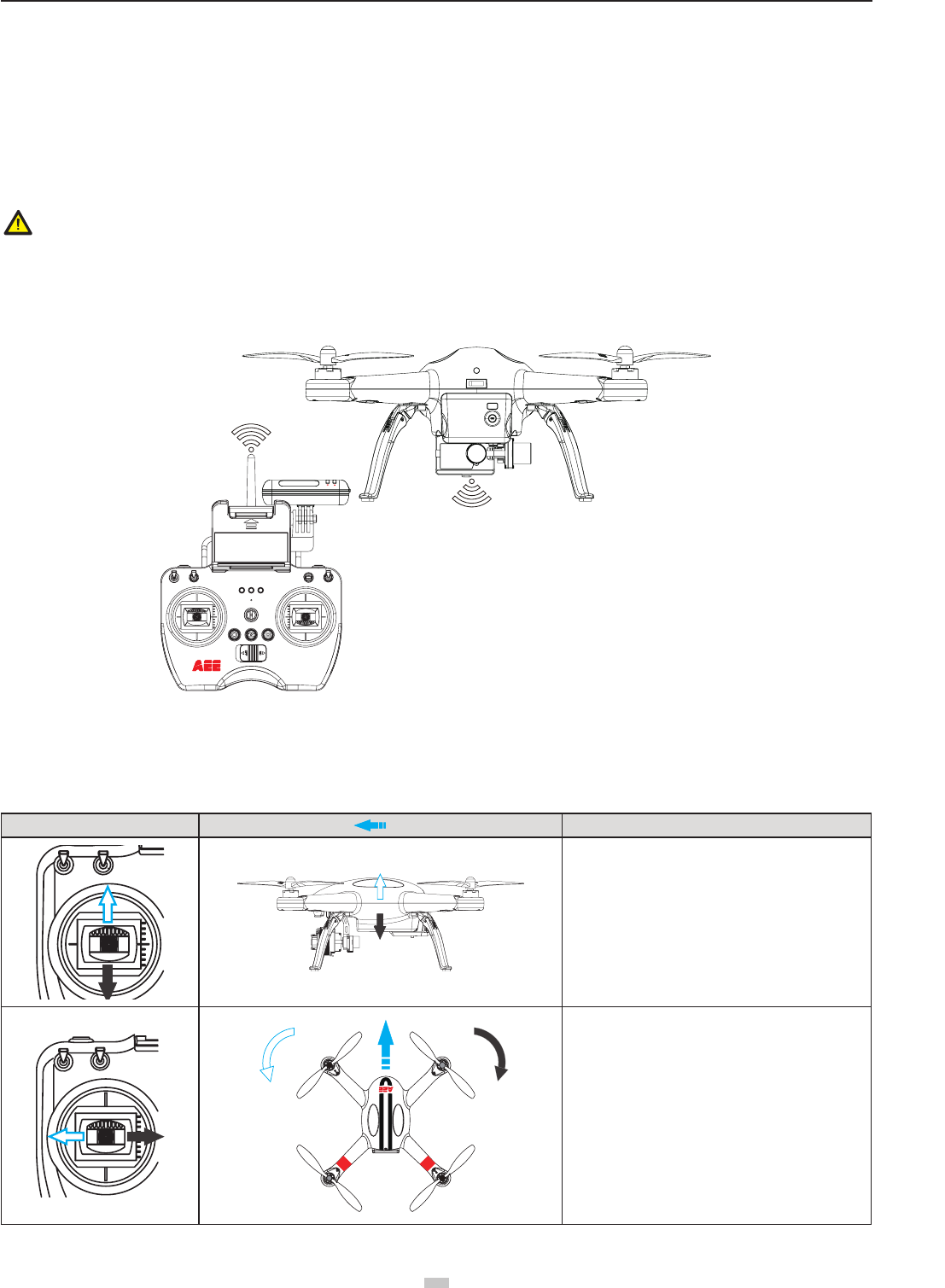
4.3 Antenna Orientation
Keep the remote control antenna pointing skyward, and ensure there are no obstacles between Remote control and receiver antennas, to ensure maximum remote
control range during ight.
Figure 15
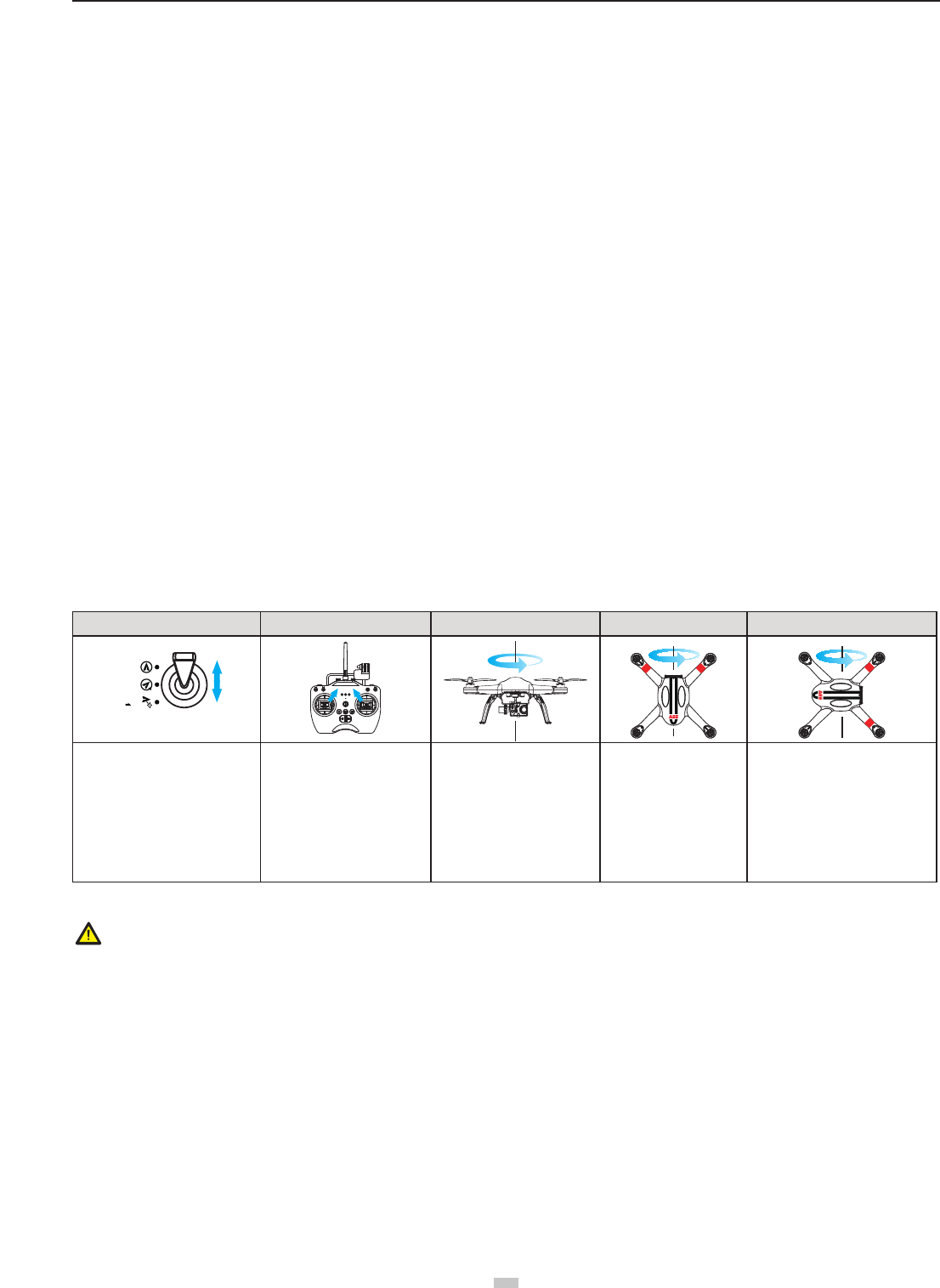
4.4 Operating the Remote control
Joystick at center / neutral: Control joysticks of remote control are at the central position�
Joystick deviation distance:The distance the Remote control joystick deviates from its center position�
Remote control (U.S. Mode) Quadcopter Direction(" " indicates nose direction) Operation Details
Vertical movements on the left joystick control quadcopter
elevation�
Push the left joystick up to ascend and down to descend�
When both joysticks are centered (neutral), the
quadcopter will hover in place (height is automatically
set)�
Push the left joystick upwards beyond the center (neutral)
position to take off� (Push the left joystick slowly to
prevent sudden and unexpected elevation)�
Horizontal movements on the left joystick, controls the
rudder�
Push left to rotate quadcopter counterclockwise and right
for clockwise. If the joystick is centered, the quadcopter
ies in the same direction without rotating.
The joystick controls the quadcopter’s rotating velocity�
The more the joystick is moved the faster the quadcopter
will rotate�
For maximum range and reliability, Remote control antenna
should point skyward with no obstructions between it and the
receiver antenna on Quadcopter� Obstructions may cause you
to lose control of the quadcopter� Ensure mobile device holder
and Repeater do not block the antenna�
aee.com
14
Vertical movements on the right joystick, controls the
quadcopter’s forward & backward pitch�
Push up to y forward and down to y backward.
The quadcopter will keep level and straight if the joystick
is centered�
Push the joystick further to increase pitch angle and
faster ight velocity.
Horizontal movements on the right joystick control left
and right pitch�
Push left to y left and right to y right.
The quadcopter will keep level and straight if the joystick
is centered
Push the joystick further to increase pitch angle and
faster ight velocity.
S2 S2S2 NULL
Position-1 Position-2 Position-3
The S2 switch is used for calibration of the joystick� Turn
S2 to position 3, then turn on the remote control, and at
this time the status indicator starts blinking (indicating
joysticks calibration starts)� Turn the left and right
joysticks clockwise and counter-clockwise respectively at
the maximum stroke for two circles, and then release the
joysticks� (ensure that the joysticks stay at the maximum
stroke throughout this process) Then, the status indicator
in the middle will go out. Last, turn S2 to position 1 , the
photo shooting & video recording indicator will light up
(green) . Now the calibration completes successfully.
S4:GPS S4:NRM S4:F M
Position-1 Position-2 Position-3
The S4 switch is used to switch the ight mode. Position
1 (GPS) is GPS mode; position 2 (NRM) is Normal mode;
position 3 is Follow Me mode
● In GPS mode, when all joysticks are in the neutral position, the quadcopter hovers at a xed-point.
● In Normal mode, when all joysticks are in the neutral position, the quadcopter remains level, but may drift in a horizontal direction.
● When S4 switch to GPS Mode, the motor can not be turned on until GPS is ready (the tail light remains on).
4.5 Frequency Pairing between Remote control and Receiver
The Remote control and receiver are paired before delivery. Normally, you can skip this procedure and directly use the quadcopter. However, if you change the
Remote control or Receiver, frequency-pairing is required.
Frequency Pairing Procedures
(1) Important: Be sure to remove propellers before pairing to avoid accidental injury�
(2) When the remote control is turned off, power on the quadcopter. Now the arm lights and the quadcopter tail light come on. When a "beep" sound is heard, turn
on the remote control; the remote control power indicator (red) will come on. When the "status indicator" on the remote control changes from red to blue, it
indicates pairing is successful�
(3) If the "status indicator" on the remote control does not change from red to blue (i.e. remains in red), repeat step (2) until the pairing is successful.
5 Preparing the Repeater
Quadcopter Wi-Fi Repeater is a wireless communication device that operates within the 2�4 GHz frequency band� It is used to extend the communication distance
between the mobile device and Quadcopter. Communication distance is affected by the surrounding environment, such as blockages due to trees, signal reection
by buildings, interference by other same frequency bands, etc., affecting effective communication distance. Before every ight, ensure the Wi-Fi Repeater works
properly, otherwise communication issues between the mobile device and Quadcopter may occur.
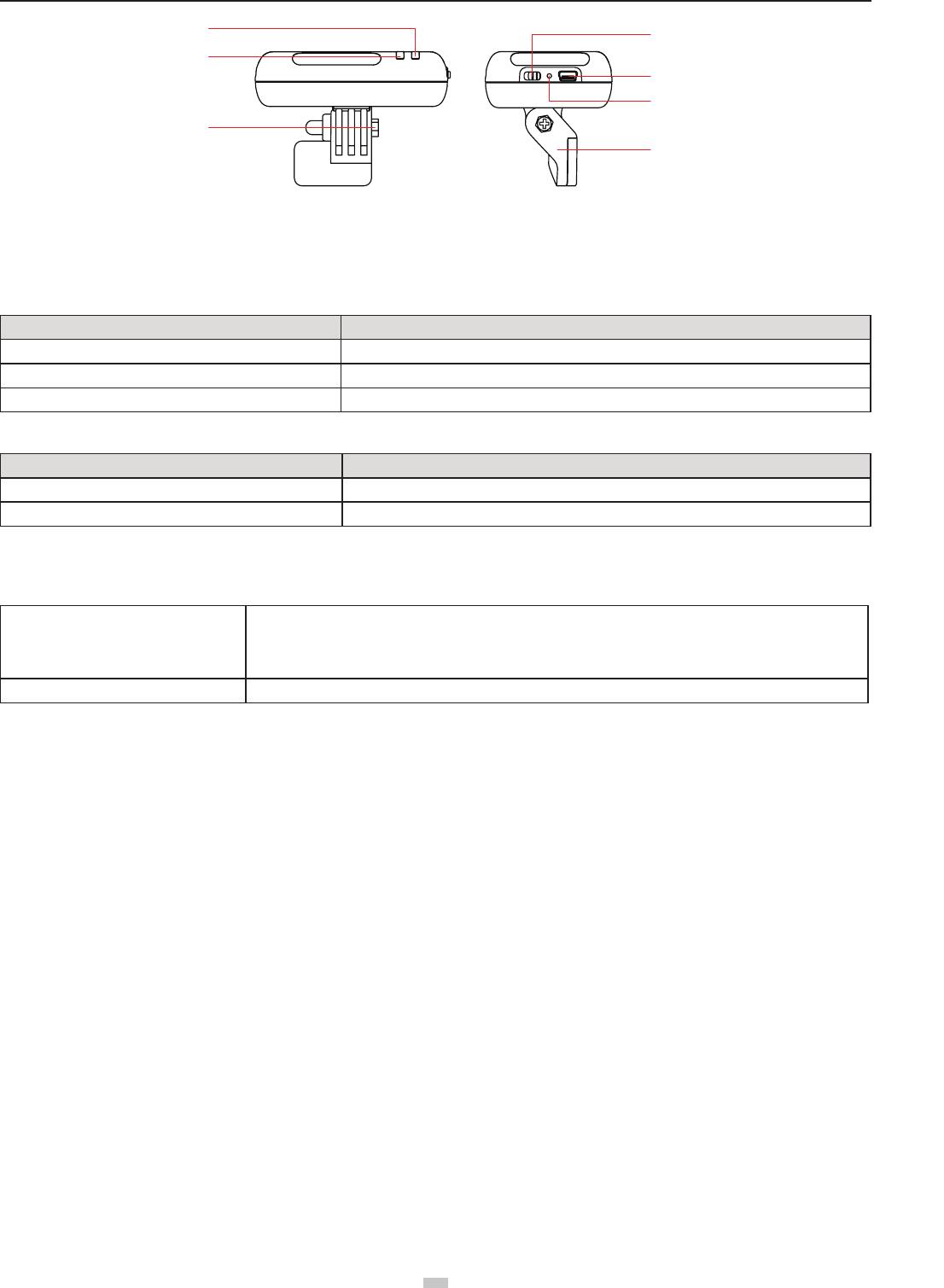
5�1 Introduction
15
aee.com
15
[ 1 ]
[ 2
]
[ 3
]
[ 4 ]
[ 5 ]
[ 6 ]
[ 7 ]
Figure 16
[ 1 ] Power Indicator [ 2 ] Wi-Fi Indicator [ 3 ] Lock screw [ 4 ] Power Switch
[ 5 ] Charging Port (Mini USB port) [ 6 ] Pairing Button [ 7 ] Repeater Base
5.1.1 Wi-Fi Indicator
Indicates Repeater’s Wi-Fi status
Wi-Fi Indicator Description
Blue light is ON Wi-Fi Repeater is working properly
Blue light blinks fast (1.5s OFF, 0.3s ON) Wi-Fi Repeater is pairing with airborne Camera
Blue light blinks slowly (3s OFF,0.3 ON) Wi-Fi Repeater is successfully paired
5.1.2 Power Indicator
Indicates Repeater’s power supply status�
Power Indicator Description
Red light is ON Repeater power supply is normal or charging completes
Red light blinks Repeater is charging, or Repeater power is running out, please charge as soon as possible
5.1.3 Pairing Button
When the repeater is on, press and hold the Pairing Button for 3 seconds, the repeater will automatically restart for code re-pairing. Press and release the Pairing
button to check repeater's power level�
Press Pairing button
Press Pairing button once:
If Power Indicator blinks once, indicates that repeater has over 80% charge available
If Power Indicator blinks twice, indicates that repeater has over 50% charge available
If Power Indicator blinks three times, indicates that repeater is running out of Power
Long press Pairing button (3 seconds) Repeater restarts and you can re-pair codes
5.1.4 Code Pairing
If the Wi-Fi indicator fast blinks blue (1.5 seconds OFF, 0.3 seconds ON), or keeps ON, it is necessary to carry out pairing please re-pair with following steps:
(1)Switch on the power switch and Wi-Fi switch of came,then switch on the power switch of repeater.
(2)After the Wi-Fi indicator of camera blinks, and Wi-Fi indicator of repeater is on, press Paring Button of repeater until Wi-Fi indicator(blue) of repeater blinks
fast(0.3s on,1.5s off). Then press the "video recording stop button"of camera immediately (1 time per second).
When the repeater blue light indicator slow blinks(0.3s on,3s off), this indicates the paring completes.
(3)If pairing fails, please repeat step 1 and step 2.
5.2 How to use
Charging the Repeater
Connect the repeater to the repeater Adapter through the Mini USB port� It takes about 2 hours to fully charge the battery�
● Ensure the repeater has sufcient charge before each ight.
Switching on the Repeater
(1) Toggle Repeater power switch to ON.
(2) Wait until the Wi-Fi indicator blinks blue, indicating the Repeater is communicating properly.
(3) While using, ensure the Repeater’s LED side faces you, and ensure that visibility between the Repeater and quadcopter is unobstructed, to obtain maximum
communication distance�
● After the ight, in addition to switching off the quadcopter and remote control, remember to switch off the Reapeater, or else the Repeater’s battery will be
depleted�
6. Use the Tracker GT10
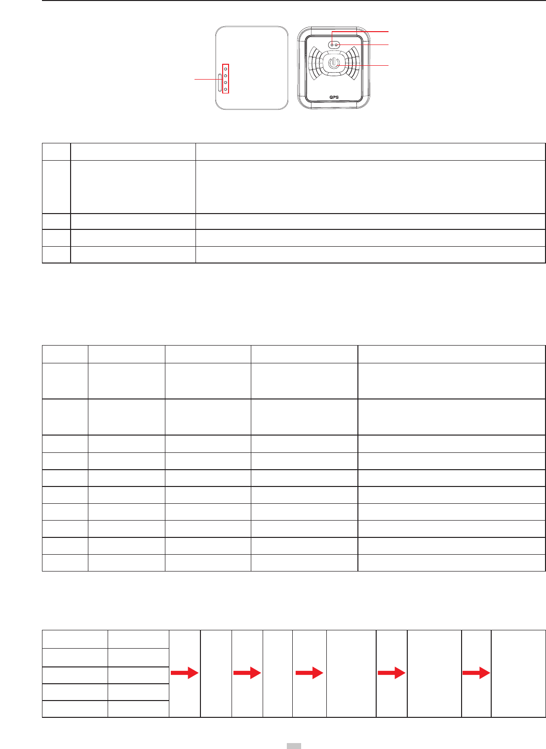
6.1 Keys and Indicators:
aee.com
16
Charging contacts
Power indicator
Statu indicator
Power / function key
6.2 Description of Keys and Indicators:
No. Name Description
[ 1 ] Power/function key
In power-off state, long press it for 3s to power on the tracker. Press and hold the Power button until the red
indicator is lit. After 3 seconds, the green indicator starts blinking, indicating the startup is completed.
In power-on state, long press it for 3s to power off the tracker. Press and hold the Power button until the green
indicator goes out. After 3 seconds, the red indicator goes out, indicating the shutdown is completed.
Initial code pairing: press it for 3 times at an interval of 2s to trigger the code pairing function�
[ 2 ] Power indicator Power indicator is red
[ 3 ] Statu indicator Status indicator is green
[ 4 ] Contacts Charging contacts�
※Note:
1. Code pairing process: turn on the tracker and trigger its code pairing function; turn on the quadcopter, and its built-in 5.8GHz module will auto proceed with the
code pairing process. In the code pairing process, the distance between the tracker and quadcopter should be less than 10m.
2. After the code pairing function is triggered, the tracker will auto exit the code pairing state if the code pairing process is nished successfully within 30s. If no code
pairing device is found or the code pairing process fails within 30s, the tracker will also auto exit the code pairing function.
6.3 Indicators on the tracker
SN Status Red indicator Green indicator Notes
1 During startup process ON Green indicator blinks after 3
seconds
Press and hold the Power button until the red indicator
is lit. After 3 seconds, the green indicator starts blinking,
indicating the startup is completed�
2During shutdown
process
Red indicator goes out
after 3 seconds OFF
Press and hold the Power button until the green indicator
goes out. After 3 seconds, the red indicator goes out,
indicating the shutdown is completed�
3No device to pair with / Blinking fast Blinking 10 times per second
4 During code-pairing / Blinking fast Blinking 5 times per second
5 Searching GPS signal / Indicator’s blinking sequence 1 Remaining on → blinking fast for 3 times
6 GPS signals are OK / Green indicator remains on
7 Abnormal system / Green indicator goes out Restarting is required
8 Charging battery Blinking slowly / Blinking 1 times per second
9 Battery charged fully Remaining on /
10 Low battery power Blinking fast / Blinking 10 times per second
6.4 Operating Instructions
6.4.1 Operating Steps:
Component Startup Time
Turn
on the
quad-
copter
Start
the APP
on the
mobile
device
Perform
the takeoff
operation of
the quadcopter
Turn the mode
switch of the
remote control to
“F-M”
The quadcopter
will enter the
follow-me video
recording mode.
Camera 20s
Repeater 22s
Remote control 10s
Tracker 10s
17
aee.com
17
6.4.2 Follow-me Video Recording:
1. Start the video recording mode: the quadcopter will auto adjust the ight altitude to 10m and y horizontally to the position 15m away from the tracker.
2� In the Follow-me : the camera lens on the quadcopter will always face the GT10 wearer�
3. When the GT10 wearer moves forward or backward, the quadcopter will follow him to y forward or backward.
4. If the GT10 wearer stays still, the quadcopter will hover.
5. When the GT10 wearer ascends or descends, the quadcopter will follow him to ascend or descend.
6.4.3 Working Conditions:
1� Use the Tracker in an open and accessible area only�
2. The GT10 wearer should not move at a speed exceeding 10m/s, or the quadcopter will enter the out-of-control mode. In such case, please use the mode
switch on the remote control to switch the mode�
6.4.4 How to Enter Follow me Mode
※ Case 1: in power-off status, when you turn on the quadcopter and repeater, and turn S4 mode switch to “F_M mode”, the quadcopter will not enter the Follow
me mode�
※ Case 2: if the quadcopter is ying at a distance ≤100m away from the tracker (the tracker has been connected to the quadcopter), when you turn S4 mode
switch to “F_M mode”, the quadcopter will take the shortest route to auto y to the position 10m over the ground and 15m away from the tracker, and make
the camera face the tracker�
※ Case 3: if the quadcopter is ying at a distance >100m (beyond the tracker’s communication distance) away from the tracker, when you turn S4 mode switch
to “F-M”, the quadcopter’s ight status (e.g. hovering) will remain unchanged.
7 Downloading and Installing AEE AP+ App
Download AEE App (iOS / Android)
Scan QR Code above
Download the AEE AP+ App to watch live video when using Quadcopter, through the following method. For iOS
users, please search "AEE AP+" in the App Store, download and install the App on your mobile device. For Android
users,please search "AEE AP+ " in the Google Play.
ANDROID APP ON
AEE AP+ iOS 6.1 or above Android 4.0 or above
Compatible Mobile Devices
iOS (system version iOS6.1 or above): Applicable for iPhone 4s, iPhone 5, iPhone 5s, iPhone 5c, iPod Touch 4 and iPod Touch 5. iPad 3, iPad 4, iPad mini and iPad
Air can also be used�
Android (Systemversion 4.0 or above), Applicable for mainstream models can be used.
● AEE will provide updates on future support for more types of mobile devices.
8 Connecting the Camera
Follow the below procedures to connect the camera and the mobile device:
(1)Power on the Remote control,Camera and Wi-Fi Repeater. Note:Do not power on the quadcopter before Wi-Fi function of camera starts up.
(2)Wait for about 22s, the Wi-Fi indicator(blue) of camera blinks and the the Wi-Fi indicator(blue) of Repeater blinks slowly(0.3s on,3s off). Now open the Wi-Fi
function of mobile device� Please put the mobile device close to the repeater�
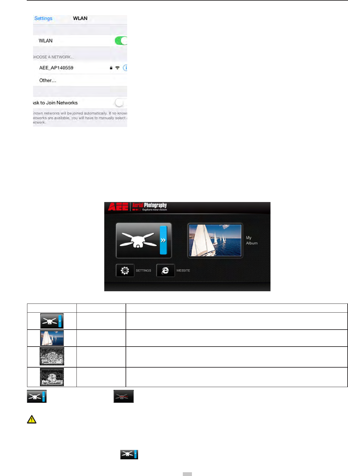
(3)Select “AEE_AP******”from the Wi-Fi network list and join in it.
● Please make sure that the mobile device close to the Wi-Fi repeater in order to get better performance of video transmission.
aee.com
18
Select this network and enter the password "AEE12345" to join the network�
Figure 17
9 Using AEE AP+ App
AEE AP+ is mainly used for remote control of the camera. It can achieve photo shooting, video recording and camera parameter setting, as well as display of ight
parameters�
1.Main Menu
After opening the APP, you can view the current condition of Wi-Fi connection and the major functions:
Figure 18
Icon Name Description
Camera Showing the Wi-Fi connection status
If Wi-Fi connection is already successful, click it to access the main interface for shooting
Album Click it to access the album interface
Settings Click it to access the APP setting interface
Website Connect to AEE‘s ofcial website
Connection successful Connection failed
Notice: When using the camera interface and the album, the mobile device should be rst connected to the Wi-Fi network of the quadcopter
•If the mobile device has an incoming call during ight, the preview image on the mobile device will be covered by call interface. In order not to endanger the ight
safety due to distraction, you are suggested not to answer any call during ight.
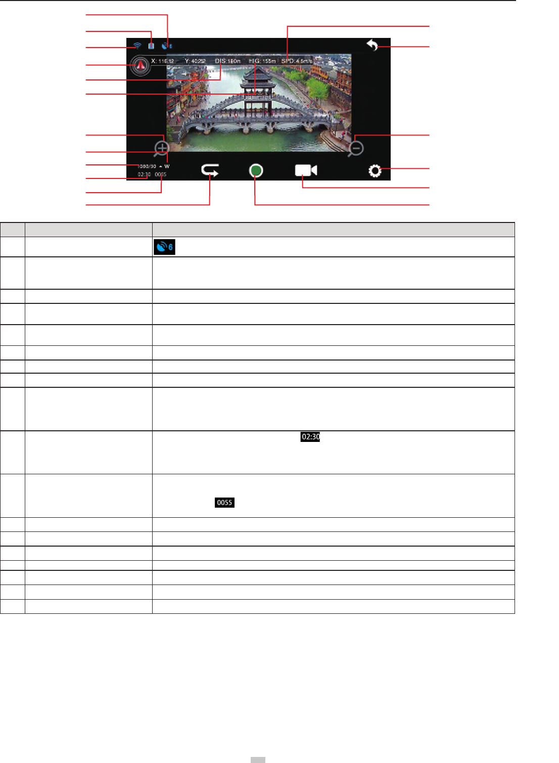
2.Main Shooting Interface
If Wi-Fi connection is already successful, click " "to show the following main shooting interface on the smart device�
19
aee.com
19
[2]
[1] [13]
[14]
[15]
[16]
[17]
[18]
[3]
[4]
[5]
[6]
[7]
[8]
[9]
[10]
[1
1]
[12]
Figure 19
No� Function Description
[ 1 ] Number of GPS satellites searched Indicates that currently the positioning signals of 6 satellites have been received
[ 2 ] Quadcopter battery level
There are totally four bars used to indicate in a real-time manner the remaining battery level of the quadcopter; 1
bar indicates 25% of the battery life is left; 2 bars indicate 50% left; 3 bars indicate 75% left; 4 bars indicate battery
is full.The level status changes with the flight.
[ 3 ] Wi-Fi signal intensity Shows in a real-time manner the intensity of Wi-Fi signal of mobile device. more bars indicate stronger Wi-Fi signal
[ 4 ] Flight parameter icon After clicking it, the interface will display the flight parameters: distance, altitude and speed, as shown in the figure
below; after clicking it again, the flight info bar will be closed
[ 5 ] Distance between quadcopter and
home point Shows the horizontal distance between the quadcopter and the home point
[ 6 ] Flight height of quadcopter Shows the vertical distance between the quadcopter and the home point
[ 7 ] Zoom in button Click it once to zoom in once; maximum 4x zooming is supported
[ 8 ] View angle indication W indicates wide (W) view angle is adopted
[ 9 ] Video recording resolution
In video recording mode: Indicates the video recording resolution is 1080/30fps
Click the triangle drop-down button to expand the available resolution options
In photo shooting mode: Indicates the photo shooting resolution is 12M pixels
Click the triangle drop-down button to expand the available resolution options
[ 10 ] Remaining video recording time
In video recording mode, this number indicates that the Micro-SD card allows another 2.5h of recording
under the current camera settings
In photo shooting mode, this number indicates that the Micro-SD card allows another quantity of photos to be taken
under the current resolution setting
[ 11 ] Number of video files / photo files saved
Number of video files saved: The number of files shown varies with different modes (video recording, photo
shooting)
In recording mode: indicates that 55 video files have been recorded by the camera
In photo shooting mode: this number indicates 55 photos have been taken by the camera.
[ 12 ] Playback button Click it to access the album interface
[ 13 ] Current flight speed of quadcopter Shows in a real-time manner the current horizontal flight speed of the quadcopter
[ 14 ] Return button Return to the previous level
[ 15 ] Zoom out button Click it once to zoom out once; maximum 4x zooming is supported
[ 16 ] Camera setting button Click it to access the camera setting interface; see the “Camera Settings” section for details
[ 17 ] Camera function selection button Click the icon to expand the camera function options
[ 18 ] Camera function operation button This button can be operated to achieve different functions in different shooting modes
aee.com
20
Flight
After installation, please conduct ight training (for example: Flight simulator training or professional training). Ensure that all ights are carried out in a suitable
environment�
Flight Environment Requirements
(1) Do not use the quadcopter in severe weather conditions, such as strong winds (category 4 and above), snow, rain and fog.
(2) Fly in an open area without tall buildings� Presence of large number of steel buildings in the area will affect the onboard compass�
(3) Keep Quadcopter away from obstacles, people, power lines, trees, shelters, surface of the water, etc., during ight.
(4) Reduce the chance of electromagnetic interference by not ying in areas with high levels of electromagnetism (such as near mobile phone base stations or
towers)�
(5) This product cannot be used in The Antarctic Circle and The Arctic Circle�
(6) Do not y the quadcopter within restricted or no-y zones, and abide by local laws or regulations.
Pre-ight Check:
(1) Ensure Remote control, Quadcopter, Wi-Fi Repeater and mobile device are fully charged.
(2) Ensure propellers are correctly assembled�
(3) Ensure the Micro SD card is properly loaded before photo capture and video recording�
(4) Ensure the Quadcopter, Remote control and other equipment are working properly after powering on.
(5) Check if motors start properly after the quadcopter is switched on. At this time, disassembling propellers is recommended for safety.
(6) Check if the AEE AP+ App is properly connected to the camera�
1 Compass Calibration
Compass calibration is required before rst time use otherwise the system may not work properly, affecting ight safety. The compass is sensitive to electromagnetic
interference from other electronic devices, which can cause abnormal compass data leading to poor ight performance or even ight failure. Regular calibration is
required for optimum performance�
● Do not calibrate the compass in a strong magnetic eld.
● Do not carry ferromagnetic material, such as keys, cell phones, etc., while calibrating the compass.
1.1 Calibration Procedures
Choose an open space to conduct calibration� Start the Remote control and quadcopter and ensure they work properly� Follow the below procedures to calibrate the
compass:
1 2 3 4 5
S4
GPS
NRM
F M
After the quadcopter powers
on(about 20 seconds). Swich S4
for more than 5 times between
GPS and Follow Me mode. The
quadcopter will enter calibraion
standby mode(the tail light blinks
fast).
Toggle the joysticks to the
position as in the follow figure.
Front indicator (green) starts
blinking ,Then release the
joysticks.Compass calibration
command has been sent
successfully.
Rotate Quadcopter 360°
horizontally
(2 turns)
Rotate Quadcopter 360°
vertically
2 turns (Nose down )
Rotate Quadcopter vertically (Nose
leftward)until green lights off, Put
Quadcopter on the ground. Green
lights up normally after light off→
calibration successful; Green lights
blink fast after light off→calibration
failed →Recalibrate
Warning
Be sure to remove propellers before calibration, to avoid accidental injury or loss.
1.2 When to Recalibrate
(1) When compass data is abnormal, front indicator (green) blinks fast.
(2) The ight location is far from the place where last compass calibration was conducted.
(3) There are changes in quadcopter’s physical structure�
(4) The quadcopter drifts a lot while ying , such as it ies along a circle when hovering.
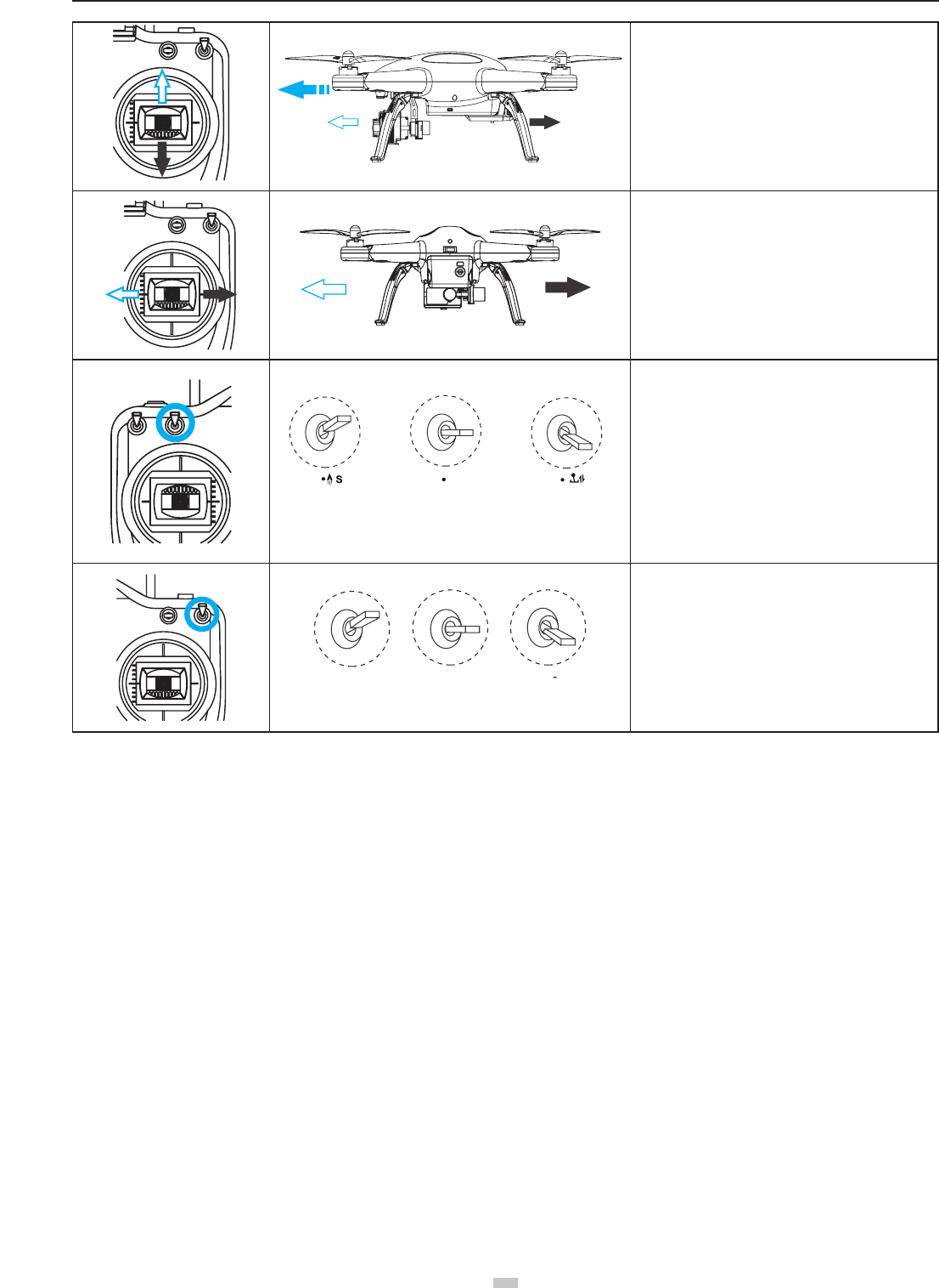
2 Starting / Stopping the Motor
2.1 Starting the motor
Toggle the joysticks as shown in the illustration (Combination joystick Command [CSC]) to start the motor� Release the joysticks simultaneously after the motors
start, then the camera will start to record video automatically.
21
aee.com
21
T
oggle Left joystick to left bottom corner
T
oggle Right joystick to right bottom corner
GPS
NRM
S1 S2 S3 S4
GPS
NRM
D
F M
S
E
S1
D
S
E
S1: E S2: OK S3: Middle S4: GPS
S2 S3 S4
NULL
NULL
When S4 switch is set to GPS Mode,
S4
The motor cannot be turned on until GPS is ready (Tail
indicator will alternate between fast blinking and on)�
Figure 20
2.2 Stopping the Motors
There are two ways to stop the motors�
Method One (Figure 21): After the quadcopter lands, toggle the throttle joystick to the lowest position and then perform CSC, the motors will immediately
stop� Release both joysticks after the motors stop�
Method 2 (Figure 22): After the quadcopter lands, toggle the left joystick to the lowest position and hold for 3 seconds to stop the motor.
Figure 21 Figure 22
● Do not execute CSC during normal ight. This will stop the motors and cause the quadcopter to drop without control.
● Camera will stop recording automatically after motor stopped.
● Toggle the joysticks quickly and accurately when performing CSC� Release the joysticks simultaneously after the motors starts or stops�
● Shutdown remote control must be after the quadcopter power off. Otherwise, the quadcopter will enter the return mode, then may case the high-speed rotation
of the propeller�
3 Basic Flight
3.1 Basic Flight Procedures
(1) Place Quadcopter on a at and open ground, and ensure Tail Indicator faces you.
(2) Power on the Camera, Remote control, Wi-Fi Repeater and Quadcopter one after the other.
(3) Launch AEE AP+ App, connect the mobile device and Quadcopter, and navigate to the Camera Preview interface.
(4)Start the motors until the GPS signal is strong enough(the Tail indicator remains on and Status Indicator is green.) at GPS mode. Or, start the motors when the
status indicator on Remote control is blue at NRM mode.
(5) Push the left joystick up slowly for a smooth take-off� Please refer to Remote control operation instructions for detailed operation procedures�
(6) Use the AEE App to capture photos and record videos, and enjoy the ight. Please refer to Using AEE AP+ App for more details.
(7) To land, gently pull down the left joystick to make the quadcopter descend slowly to the ground.
(8) After landing, execute CSC or pull the left joystick to the lowest position and hold for more than 3 seconds until the motors stop.
(9) After motors stop, power off Quadcopter, Wi-Fi Repeater and the Remote control one after the other.
● During ight if all 4 arm indicators slow blink or fast blink, it indicates the quadcopter has entered a low battery state. Please refer to Low Battery Level Alarm
Function for details�
● DO NOT move the camera manually in any case OTHERWISE it will cause the camera to be abnormal. The movement of camera can be controlled only by the
Remote Control�
General Operating Order List
Component Startup Time
Turn on the quadcopter Start the APP on the
mobile device
Perform the takeoff
operation of the
quadcopter
Camera 20s
Repeater 22s
Remote control 10s
Tracker 10s
aee.com
22
3.2 Aerial Photography Tips and Tricks
(1) Perform pre-ight checks.
(2) Capture photos and record videos during safe ight status.
(3) Capture photos and record videos in sunny weather with little wind�
(4) Set camera settings as per shooting requirements, such as video resolution, picture size, etc.
(5) Carry out a trial ight before actual ight to help plan the route and frame your photos and videos.
(6) Push the joystick as slowly as possible during ight to ensure the quadcopter ies smoothly.
4 Failsafe Protections
If the Quadcopter loses connection with the Remote control (i.e., you lose control), the Failsafe mode kicks in and the Automatic Flight Control system will control the
Quadcopter, y it back to the Home Point and land it safely. This reduces chances of losing or crashing the Quadcopter in case the Remote control signal is lost.
● Home Point: Indicates the Quadcopter's position when the Quadcopter successfully scans the GPS signal.
4.1 Scenarios when Quadcopter enters Failsafe mode
(1) When Remote control is powered off�
(2) The Quadcopter has own beyond the effective range of the Remote control signal.
(3)There is interference causing a signal problem with the Remote control�
4.2 Failsafe Procedure
In case you lose control of the Quadcopter during ight, the Quadcopter will automatically follow the below operating procedures:
(1) The Quadcopter automatically slows down and hovers in one location�
(2) If the Quadcopter regains signal from the remote control within 2 seconds, ight control returns to normal mode, and the Quadcopter will not enter Failsafe
mode and will not automatically y back to the Home Point.
(3) If the Quadcopter does not regain signal from the remote control within 2 seconds, the Quadcopter enters Failsafe mode, and initiates automatic ight control
to y back to the Home Point. The Quadcopter will now continue to hover for 15 seconds and evaluate vertical Distance to the Home Point. If the distance is
more than 25 meters, the Quadcopter will commence to y back to the Home Point. If the Distance is less than 25 meters, the Quadcopter will y up vertically
to 25 meters higher than the Home Point, and then commence to return. When the Quadcopter reaches the Home Point it will hover for 5 seconds and then
automatically land�
● To ensure the Quadcopter successfully ies back to the Home Point when it is in Failsafe mode, please take-off only after the Quadcopter successfully scans the
GPS signal�
● The Quadcopter cannot automatically avoid obstacles in its path when it is ying in Failsafe mode.
4.3 How to regain control during Failsafe Procedures
When the Quadcopter is out of control, toggle the S4 switch on the remote control several times to switch ight mode. Once the signal is restored, the remote
control will regain control, and you can continue to use the remote control to operate the Quadcopter.
5 Low Battery Level Alarm Function
When quadcopter battery power is low, you must land as soon as possible, or else the quadcopter may lose power completely and crash, damaging the quadcopter
or creating a dangerous situation. In order to prevent danger caused by low battery, Quadcopter denes Level 1 low voltage alarm (battery level under 50%) and
Level 2 low voltage alarm (battery level under 20%), and sends alarms with indicators on the quadcopter and on the Remote control .
Battery Alarm Flight indicator light status Low Power risk prompt
Low Power alarm 4 arm indicators Slow Blink
(blinks on and off in 1s intervals)
In level 1 alarm condition, Quadcopter ies normally for few minutes and then initiates
Level 2 alarm. Be cautious while ying, keep the Quadcopter within sight and do not to y
too high or too far�
Severe Low Power
alarm 4 arm indicators Fast Blink (blinks twice within 1s)
In level 2 alarm condition, Quadcopter ies normally for few minutes and then initiates
Failsafe mode and commences to automatically land. Under such a situation, please
return and land the Quadcopter as safely as possible, and do not push the throttle hard or
make big movements during ight.
During low-Power automatic landing, you can regain control of the Quadcopter by switching the ight mode switch S4. However, do not do so repeatedly, as it may:
1) Reduce battery service life due to over discharge�
2) Quadcopter may crash due to insufcient Power.
Software Upgrade Interfaces on PC
1.Software Installation
Click the icon to install the software, Follow the prompts to complete the installation.
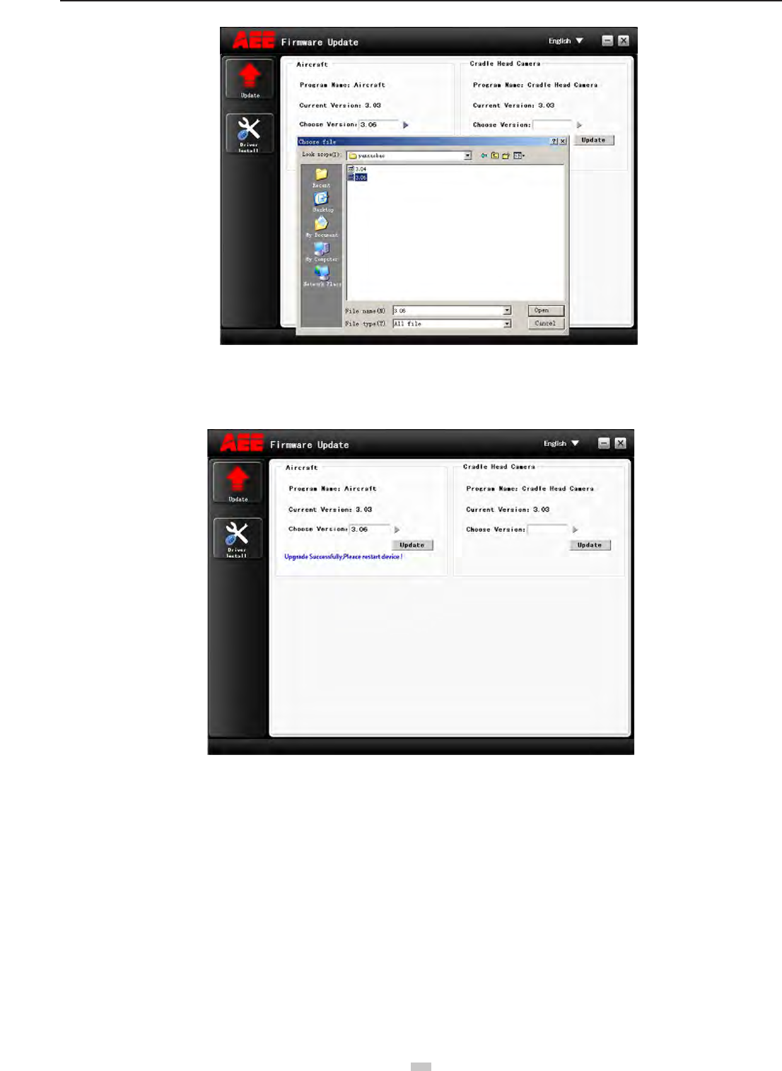
2. Driver Installation
1) Double click the icon to open the software�
23
aee.com
23
*XO\KXOTYZGRR
2)The driver should be installed for initial use. When driver installation is nished, the dialog box reading “Driver successfully installed” will pop up (see the gure
below). Click “OK” to nish the installation.
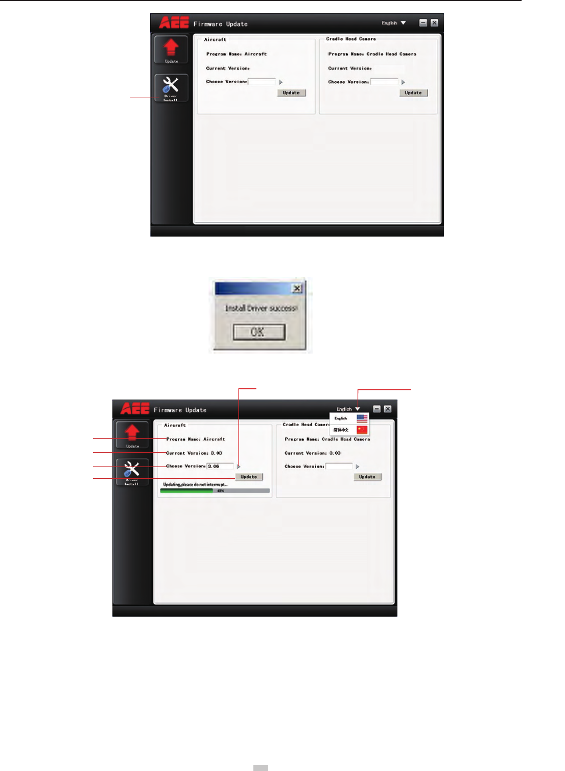
3. Interface Explanation
Update
Program Name
Language selection Browse file to be burnt
Current Version
Choose
Version
The interface of the software upgrade interface on PC is very simple� It is mainly divided into two areas: main control program
burning area, PTZ program burning area.
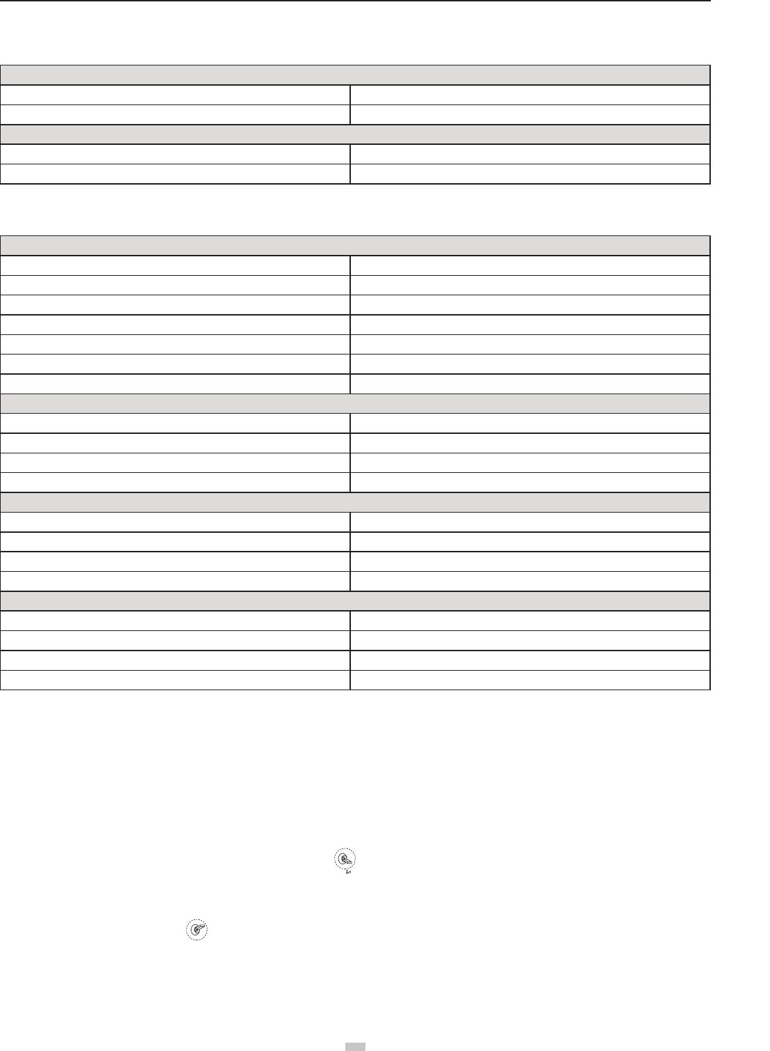
4.Upgrade Steps
1) Open the software�
2)Connect the device (e.g., Quadcopter) to the PC via the data cable; now the information of the connected PC serial port will be displayed.
Remark: After the device is connected, the device will enter the upgrade status.
3)Click the “Browse le to be burnt” button to select the le to be burnt; then click “Upgrade”. Now the software starts auto upgrade and shows the upgrade
progress bar�
aee.com
24
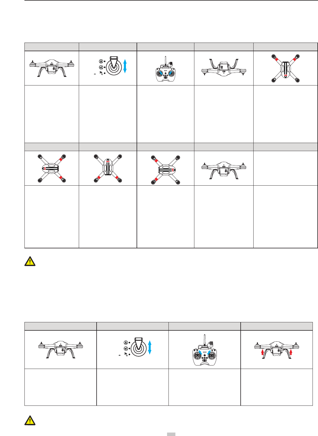
4) After the le is updated successfully, please wait for a moment. The software will display a prompt indicating successful upgrade and remind the user to restart
the device. Now the whole upgrade process is completed.
25
aee.com
25
Appendix
1 Description of Common Indicators
Normal State
Front and Rear Indicators remain ON; Tail Indicator remains on. The GPS signal is strong enough�
Front and Rear indicators remain ON, Tail Indicator Slow Blinks Searching for GPS signals
Warnings and Abnormal State
Front and Rear Indicators Slow Blinks Low Power alarm (rst-level low power alarm)
Front and Rear Indicators Fast Blink Severe Low Power alarm (second-level low power alarm)
Above indicator descriptions refer to common LED indicator states. For specic details, please refer to “Prepare the Quadcopter” in section 2.3 Flight Indicators.
2 Specications
Quadcopter
Weight 1�65kg / 3�64lbs
Hovering Accuracy Horizontal: ±2.5m / 8.2ft , Vertical: ±0.8m/2.62ft
Maximum Tilt Angle 30°
Maximum Climb / Descent Speed Climb: 6 m/s (19�69ft/s); Descend: 4 m/s (13�12ft/s)
Maximum Flight Speed 20m/s(65.62ft/s)(Not recommended)
Diagonal Length 450mm / 1�48ft
Flight Time 20min
Camera
Sensor Size 1 / 2�3
Effective Pixels 16 Megapixels (MP)
Resolution 4608x3456
HD Video Recording Maximum 1080P / 60fps (N system), 1080P / 50fps (P system), 720P/120fps
Remote control
Data Transfer Distance ≤700m (2296ft)
Working Hours 20h
Operating Current / Voltage 150mA / 6V
Battery 4 AA Batteries
Wi-Fi Repeater
Operating Frequency 2�4GHz
Communication Distance (open outdoors) ≤500m (1640ft)
Transmitting Power ≤17dBm
Power Consumption 1�5W
3 Common Troubleshooting
3�1 Solution for remote control joysticks center (neutral) position errors
When there is a big error in neutral position of remote control joysticks, the motors cannot start when performing CSC. Errors in Remote control joysticks neutral
position usually occur in two cases:
1. When quadcopter is ON and the joystick (except throttle) is not in neutral position-Solution: Move all Remote control joysticks to neutral position, and re-start the
quadcopter, to re-record the neutral position. If problem persists, it may be caused due to case.
2. Remote control joysticks have been trimmed, leading to deviation in neutral position, i.e., there is a large asymmetry in quadcopter joystick position-Solution:
Recalibrate the Remote Control�
a) The S2 switch is used for calibration of the joystick� Turn S2 to position 3
S2:
, then turn on the remote control, and at this time the status indicator starts
blinking (indicating joysticks calibration starts)� Turn the left and right joysticks clockwise and counter-clockwise respectively at the maximum stroke for two
circles, and then release the joysticks. (ensure that the joysticks stay at the maximum stroke throughout this process) Then, the status indicator in the middle
will go out. Last, turn S2 to position 1
S2:OK
, the photo shooting & video recording indicator will come on (green) and then go out 3s later. Now the calibration
completes successfully�
(b) Re-start the quadcopter, and pay attention whether or not it starts properly. If the problem cannot be solved by the above methods, please send back the remote
control to our factory for repair�
3.2 Solutions for Accelerometer Abnormalities
aee.com
26
3�2�1 Situations requiring recalibration
1) The accelerometer data are abnormal; the four arm lights blink fast�
2) The mechanical structure of the quadcopter changes�
3) The drift distance is signicant during ight.
3�2�2 Calibration steps
1 2 3 4 5
S4
GPS
NRM
F M
Place the quadcopter on a
at and still ground; turn on
the remote control and the
quadcopter in sequence
After the quadcopter is normally
powered on, turn the S4 switch
on the remote control between
positions 1 and 3 for more than
5 times (i.e., 5 switch cycles);
the quadcopter tail light will
blink fast, and the quadcopter
will enter the calibration
standby mode(S4-->NRM)
Turn the joysticks of the remote
control to a lower toe-in shape
until the four arm lights go out,
and then return the joysticks to
the middle position�
Accelerometer command has
been sent successfully
When the four arm lights start
Remaining ON again, place
the quadcopter on the ground
upside down (in order to avoid
scratch of the housing, it is
suggested that sponge should
be applied)� Turn the joysticks
of the remote control to a lower
toe-in shape until the four arm
lights go out, and then return the
joysticks to the middle position
When the four arm lights start
Remaining ON again, lean the
four supports of the quadcopter
against a wall (with the nose
facing downward) to make it
perpendicular to the ground� Turn
the joysticks of the remote control
to a lower toe-in shape until the
four arm lights go out, and then
return the joysticks to the middle
position
6 7 8 9
When the four arm lights
start Remaining ON again,
lean the four supports of the
quadcopter against a wall
(with the nose facing leftward)
to make it perpendicular to
the ground� Turn the joysticks
of the remote control to a
lower toe-in shape until the
four arm lights go out, and
then return the joysticks to
the middle position
When the four arm lights start
Remaining ON again, lean the
four supports of the quadcopter
against a wall (with the nose
facing upward) to make it
perpendicular to the ground�
Turn the joysticks of the remote
control to a lower toe-in shape
until the four arm lights go out,
and then return the joysticks to
the middle position
When the four arm lights start
Remaining ON again, lean the
four supports of the quadcopter
against a wall (with the nose
facing rightward) to make it
perpendicular to the ground�
Turn the joysticks of the remote
control to a lower toe-in shape
until the four arm lights go out,
and then return the joysticks to
the middle position
At last,If the four arm lights stop
blinking fast simultaneously,
it indicates the accelerometer
calibration is successful�
Otherwise, the accelerometer
should be recalibrated, if the
calibration is failed, the 3-Axials
gimbal will always shake which
should be specied here.
Warning: In order to avoid accidental injury or loss, please remove the propellers prior to calibration.
3.3 Solutions for Gyroscope Abnormalities
3�3�1 Situations requiring recalibration
1) The gyroscope data are abnormal; the four arm lights blink fast�
2) The mechanical structure of the quadcopter changes�
3) The drift distance is signicant during ight.
3�2�2 Calibration steps
1234
S4
GPS
NRM
F M
Place the quadcopter on a at and still
ground; turn on the remote control and
the quadcopter in sequence
After the quadcopter is normally
powered on, turn the S4 switch on the
remote control between positions 1 and
3 for more than 5 times (i.e., 5 cycles);
the quadcopter tail light will blink fast,
and the quadcopter will enter the
calibration standby mode
Turn the joysticks of the remote control
to an upper toe-out shape, wait until
the rear arm lights on the quadcopter
start blinking slowly, and then release
the joysticks� Gyro command has been
sent successfully� (Do not move the
quadcopter when it is calibrating)
At last,If the rear arm lights (red)
remain on, it indicates the calibration is
successful. Otherwise, the gyroscope
should be recalibrated�
Warning: In order to avoid accidental injury or loss, please remove the propellers prior to calibration.

27
aee.com
27
3.4 Quadcopter is out of sight and the Wi-Fi is disconnected
Turn off the remote control and let the quadcopter automatically return. Ensure there are no obstructions on the quadcopter’s return path, and ensure you are familiar
with the procedures on how to regain control of the quadcopter�
Turn off the Remote control to trigger the Failsafe mode and the quadcopter will start to y back, descend, and land at the Home Point. Ensure there are no obstacles
between the Quadcopter and the Home Point and that you are familiar with the procedure for regaining control�
3.5 Wi-Fi could not be re-connected
This is because after the mobile device disconnects from Quadcopter Wi-Fi connection, the mobile device automatically connects to other Wi-Fi networks. Please
check your mobile device is connected to the Quadcopter Wi-Fi network�
3.6 Precautions while using App on multiple mobile devices
During ight if the App is used on one mobile device and then launched on another mobile device, please make sure you completely log out from the App in the
original mobile device, so that the App can be normally used on the other mobile device.
3.7 How can quadcopter land smoothly?
Before performing CSC, pull down the left joystick to less than5% ofthe joystick level, and then execute CSC. This way you can land the quadcopter smoothly.
Limited Warranty
AEE products are guaranteed against manufacturing defects, AEE's sole obligation in the event of such defects during this period is to repair or replace the defective
part or product with a comparable part or product at AEE's sole discretion. Except for such repair or replacement, the sale, processing or other handling of this
product is without warranty, condition or other liability even though the defect or loss is caused by negligence or other fault. Damage resulting from use, accident, or
normal wear and tear is not covered by this or any warranty. AEE assumes no liability for any accident, injury, death, loss, or other claim related to or resulting from
the use of this product� In no event shall AEE be liable for incidental or consequential damages relating to or resulting from the use of this product or any of its parts�
Because of possible user resealing error, this product is not warranted against leakage in waterproof housing or any resulting damage. Returns or replacements of
parts and/or products may be subject to shipping, handling, replacement and/or restocking fees.
If you are experiencing a problem with an AEE purchase, please contact our Customer Support Team by visiting our website www.aee.com .
For product warranty period and conditions, please refer to www.aee.com for details.
Tip: If you bought this product from an AEE authorized dealer, we would recommend that you rst contact them for technical support issues
This User Manual is subject to change without prior notice�
You can check the ofcial AEE website for the latest updated version.
FCC Information and Copyright
This equipment has been tested and found to comply with the limits for a Class B digital device,
pursuant to part 15 of the FCC Rules.
These limits are designed to provide reasonable protection against harmful interference in a residential
installation. This equipment generates,
uses and can radiate radio frequency energy and, if not installed and used in accordance with the
instructions, may cause harmful interference
to radio communications. However, there is no guarantee that interference will not occur in a particular
installation. If this equipment does
cause harmful interference to radio or television reception, which can be determined by turning the
equipment off and on, the user is
encouraged to try to correct the interference by one or more of the following measures:
—Reorient or relocate the receiving antenna.
—Increase the separation between the equipment and receiver.
—Connect the equipment into an outlet on a circuit different from that to which the receiver is
connected.
—Consult the dealer or an experienced radio/TV technician for help.
This device complies with part 15 of the FCC Rules. Operation is subject to the
following two conditions:
(1)This device may not cause harmful interference, and
(2) this device must accept any interference received, including interference that may
cause undesired operation.
changes or modifications not expressly approved by the party responsible for compliance could
void the user's authority to operate the equipment.
This equipment complies with FCC radiation exposure limits set forth for an uncontrolled
environment .This equipment should be installed and operated with minimum distance 20cm
between the radiator& your body. This transmitter must not be co-located or operating in
conjunction with any other antenna or transmitter.