AEE Technology AEEAP900001 Aerial photography equipment User Manual Manual
Shenzhen AEE Technology CO., LTD. Aerial photography equipment Manual
UserManual.wiki
>
AEE Technology
>
AEEAP900001 User Manual
Manual
Navigation menu
Upload a User Manual
Namespaces
Wiki Guide
HTML
PDF
Info
Views
User Manual
Discussion / Help
Navigation
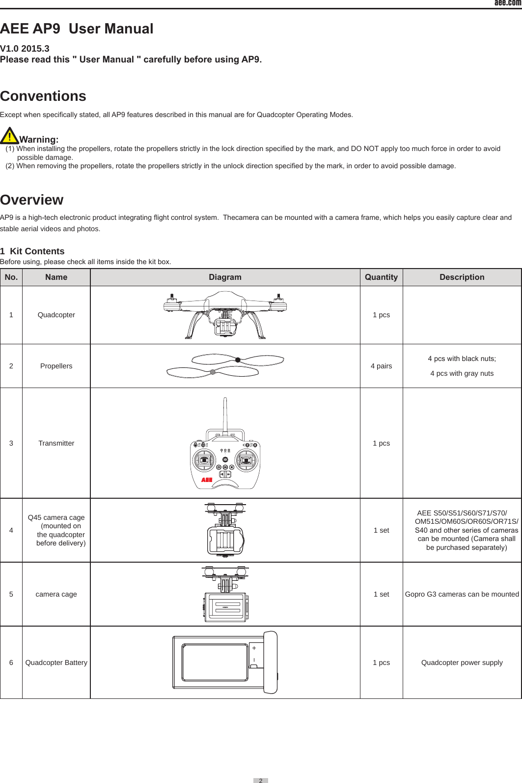
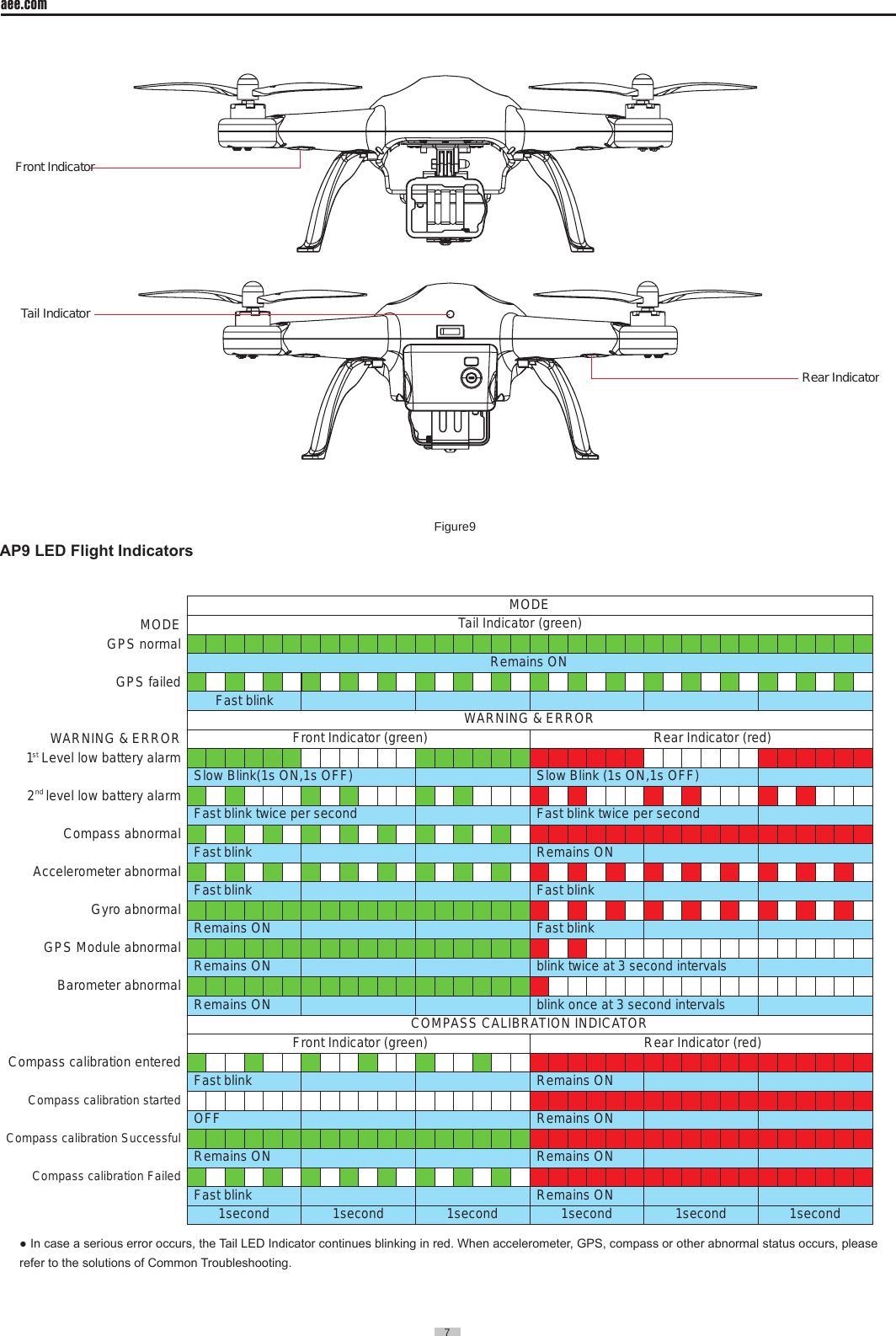
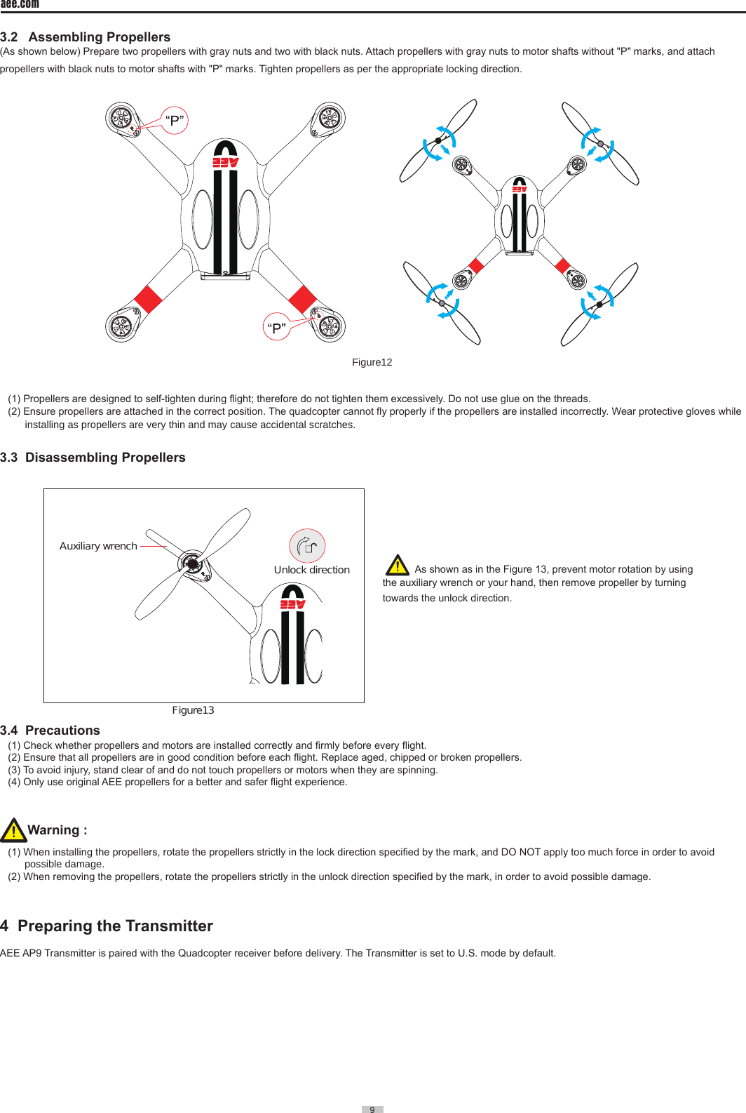
![aee.com6 2 Preparing the Quadcopter The quadcopter includes a built-in ight control system and motors etc.2.1 Introduction[ 1 ][ 2 ][ 3 ][ 4 ][ 5 ] [ 6 ][ 7 ][ 8 ][ 10 ][ 11 ][ 9 ]Figure8[ 1 ] Propellers [ 2 ] Motor [ 3 ] Front Indicator [ 4 ] Camera Cage [ 5 ] Landing Gear [ 6 ] Quadcopter Battery [ 7 ] Tail Indicator [ 8 ] Power switch [ 9 ] Rear Indicator [ 10 ] Battery Level LCD Segment Display [ 11 ] Battery Level Check button2.2 Flight Control System AEE AP9 is equipped with AEE ight control system to provide incredible ease of use and stability. In addition to supporting basic ight maneuvers such as climb, descend, roll and pitch, it also supports failsafe protection, battery level alarms and other functions.System Component Modules FunctionMaster Controller Core module of the ight control system. Connects and controls all modules together.GPS & Compass Used for positioning and navigation.Indicator Indicates current ight control system status. Used to navigate during night ight.2.3 Flight IndicatorThere are three Flight Indicators, namely, the Front indicator, Rear indicator and Tail indicator. When the Quadcopter switch is turned on, the LED Flight Indicators will be on. The Front indicator is green and the Rear indicator is red. (Hereafter use Green/Red Indicator to describe Front/Rear indicators respectively).](https://usermanual.wiki/AEE-Technology/AEEAP900001/User-Guide-2612096-Page-7.png)
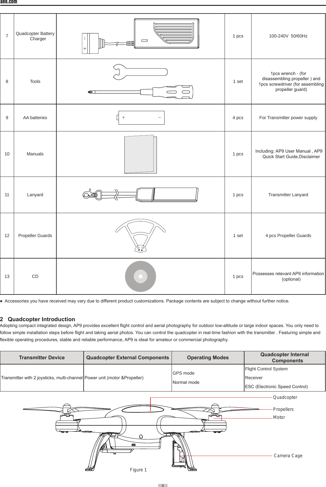
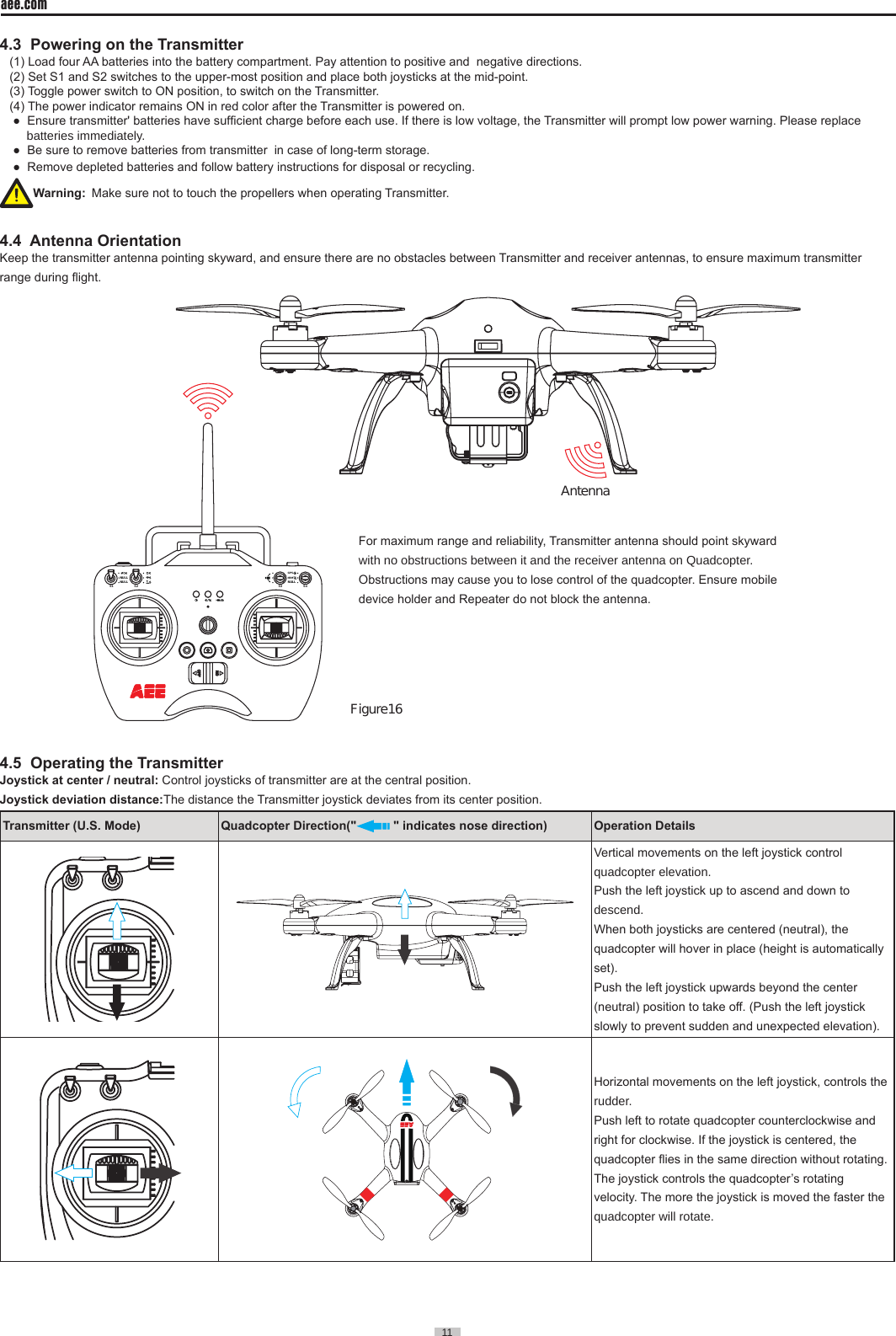
![aee.com10 4.1 IntroductionNULLS3 S4GPSNRMS2NULLNULLS1[ 1 ][ 2 ][ 3 ][ 6 ][ 7 ][ 10 ][ 14 ][ 15 ] [ 16 ][ 13 ][ 11 ][ 8 ][ 5 ][ 4 ][ 9 ][ 12 ] Figure14[ 1 ] Antenna [ 2 ] 3-position Switch S1 [ 3 ] 3-position Switch S2 [ 4 ] 3-position Switch S3 [ 5 ] 3-position Switch S4 [ 6 ] Transmitter Power Indicator [ 7 ] Status indicator [ 8 ] Photo shooting & video recording indicator [ 9 ] Battery Compartment [ 10 ] Left Joystick ("Up & Down" controls Throttle, "Left & Right" controls Yaw)[ 11 ] Right Joystick ("Left & Right” controls Roll, "Front & Back " controls Pitch) [ 12 ] Strap Hole [13 ] Video Stop Button(Reserved function) [ 14 ] Strap Hole(Reserved function) [ 15 ] Airborne Shutter Button(Reserved function) [ 16 ] Transmitter Power SwitchWarning : To avoid accidental Injury, STAND CLEAR of and DO NOT touch propellers or motors when operating Transmitter.Function denition for toggle switch S1~S4 as below:S1 3 positions, 1. : Normal ight 2. Reserved for future upgrading 3. Reserved for future upgrading S2 3 positions, 1. : Joystick calibration OK 2. : (Reserved function) 3. : Calibrating JoystickS3 3 positions, related control to servo (Tilt up)Stop(middle)(Tilt down)Note: This function is not available on AP9.S4 3 positions, 1.GPS : GPS mode 2. NRM : Normal mode 3. NULL : null (reserved)4.2 Status Indicator on Transmitter Upon startup of the quadcopter, you can judge the quadcopter status according to the status indicator on the Transmitter. As shown in Fig. 15; there are three indicators, including (from left to right): transmitter power indicator - red; status indicator - three color (red/green/blue);Photo shooting & video recording indicator - green. NULLS3 S4GPSNRMS2NULLNULLS1 Figure15(1) When Transmitter battery power is low, a warning alert sounds.(2) When Quadcopter battery power is low, a warning alert also sounds.Remote Control IndicatorsDesignation Power indicator Status indicator (three-color)Red light /Green light /Blue light Photo shooting & video recording indicatorFunctional status Red light●Red light● /Green light●/Blue light● Green light●Power on Remaining onNRM mode: blue light (continuous)ON --> OFFGPS mode: green light --> red light --> green light (satellite searching successful)GPS mode: green light --> red light (satellite searching failed)NRM-->GPS Remaining on Satellite searching successful: blue light --> green lightSatellite searching failed: blue light --> red light OFFGPS-->NRM Remaining on Satellite searching successful: green light --> blue lightSatellite searching failed: red light --> blue light OFF](https://usermanual.wiki/AEE-Technology/AEEAP900001/User-Guide-2612096-Page-11.png)
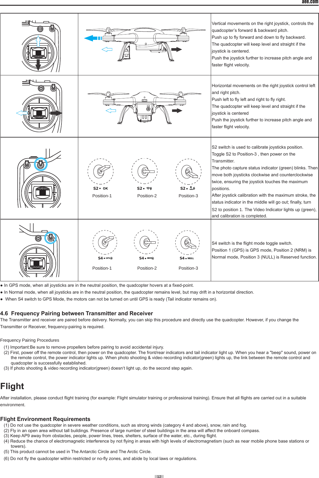
![13 aee.com13 Pre-ight Check:(1) Ensure Transmitter, Quadcopter are fully charged.(2) Ensure propellers are correctly assembled.(3) Ensure the Quadcopter, Transmitter and other equipment are working properly after powering on.(4) Check if motors start properly after the quadcopter is switched on. At this time, disassembling propellers is recommended for safety.1 Compass Calibration Compass calibration is required before first time use otherwise the system may not work properly, affecting flight safety. The compass is sensitive to electromagnetic interference from other electronic devices, which can cause abnormal compass data leading to poor flight performance or even flight failure. Regular calibration is required for optimum performance.● Do not calibrate the compass in a strong magnetic eld. ● Do not carry ferromagnetic material, such as keys, cell phones, etc., while calibrating the compass.1.1 Calibration Procedures Choose an open space to conduct calibration. Start the Transmitter and quadcopter and ensure they work properly. Follow the below procedures to calibrate the compass:NULLS3 S4GPSNRMS2NULLNULLS1Toggle the joysticks to the position as in the follow figure. Rotate Quadcopter 360° vertically2 turns (Nose down )Rotate Quadcopter vertically(Nose leftward)until green lights offGreen lights blink fast after light off Calibration failureGreen lights up normally after light offCalibration successPut AP9 on the groundRecalibrateStart horizontal calibrationFront indicator (green)starts blinkingThen release the joysticksStart calibrationTop left joystick to top right cornerTop right joystick to top left cornerRotate Quadcopter 360° horizontally (2 turns)WarningBe sure to remove propellers before calibration, to avoid accidental injury or loss. 1.2 When to Recalibrate(1) When compass data is abnormal, front indicator (green) blinks fast.(2) The ight location is far from the place where last compass calibration was conducted. (3) There are changes in quadcopter’s physical structure.(4) The quadcopter drifts a lot while ying , such as it ies along a circle when hovering.Warning Be sure to remove propellers before calibrating to avoid accidental injury.2 Starting / Stopping the Motor 2.1 Starting the motor Toggle the joysticks as shown in the illustration (Combination joystick Command [CSC]) to start the motor. Release the joysticks simultaneously after the motors start, then the camera will start to record video automatically. NULLS3 S4GPSNRMS2NULLNULLS1Toggle Left joystick to left bottom corner.Toggle Right joystick to right bottom corner. S1: S2: S3:S4:S2S1 S3 NULL S4GPSNRMGPSFigure17When S4 switch to GPS Mode, NULLS4GPSNRM the motors can not be turned on until GPS is ready .](https://usermanual.wiki/AEE-Technology/AEEAP900001/User-Guide-2612096-Page-14.png)