AEE Technology AEED0100001 Unmanned Aircraft Systems (Ground Control Station) User Manual
Shenzhen AEE Technology CO., LTD. Unmanned Aircraft Systems (Ground Control Station) Users Manual
UserManual.wiki
>
AEE Technology
>
AEED0100001 User Manual
Users Manual
Navigation menu
Upload a User Manual
Namespaces
Wiki Guide
HTML
PDF
Info
Views
User Manual
Discussion / Help
Navigation

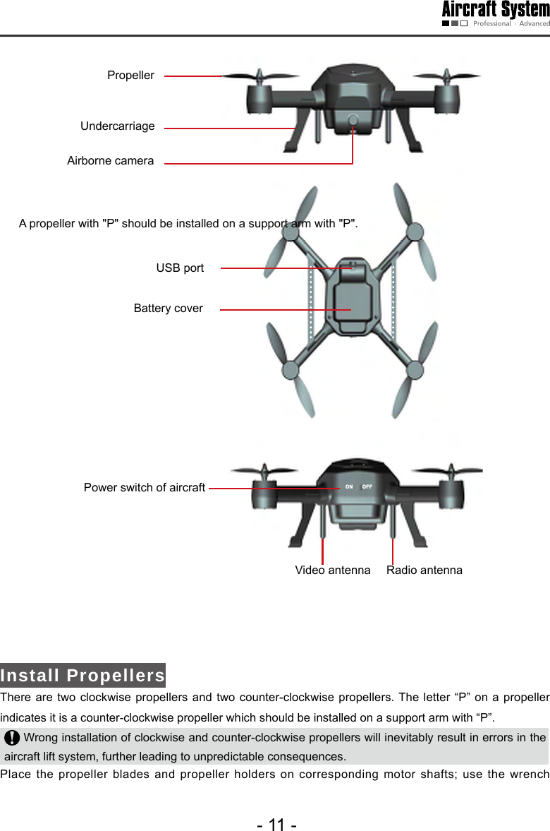
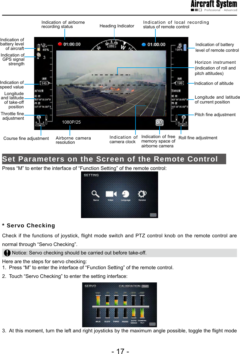
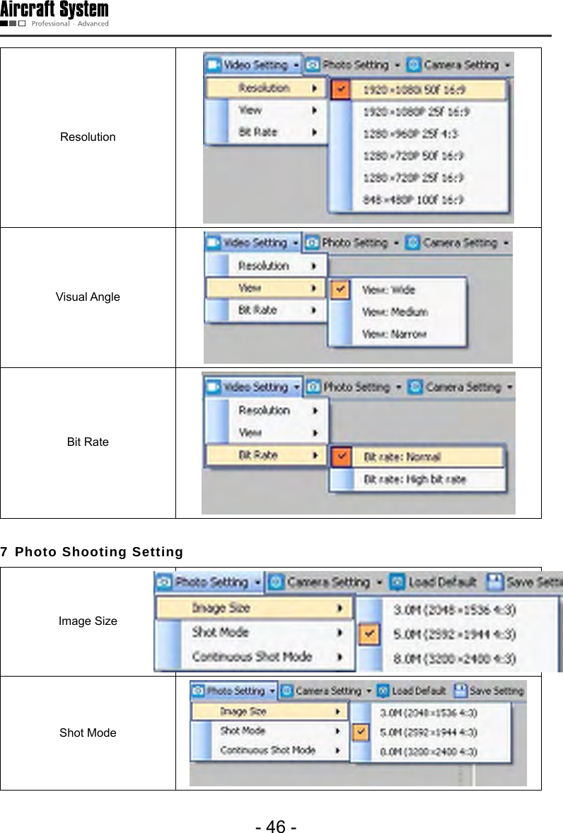
![- 18 -switch and rotate the PTZ control knob, and the relevant indication bars will pulsate correspondingly; the functions of roll, pitch, throttle, course, automatic ight switch and angle adjustment of airborne camera can be checked. Notice: During servo checking, please make sure that the aircraft power switch is in the OFF state, in order to avoid accidental startup of the aircraft. * Joystick Calibration Touch “[Start]” for joystick calibration in the interface of “Servo Checking” in the above step; turn the left and right joysticks for 5-10 circles by 360° to enter the state of joystick calibration; indication bars of roll, pitch, throttle and course will pulsate correspondingly; click “DONE” to finish the calibration process. Carry out servo checking after completion of calibration; it is OK if servo checking shows normal result; otherwise, recalibration is required. Notice: During joystick calibration, please make sure that the aircraft power switch is in the OFF state, in order to avoid accidental startup of the aircraft.* Camera Setting Touch “ ” to enter the interface of “Airborne Camera Setting” shown below: Video Recording Settings , Photo Shooting Settings , and Local Settings of Airborne Camera ) Video Recording Settings 1) Setting Image Resolution](https://usermanual.wiki/AEE-Technology/AEED0100001/User-Guide-2442982-Page-21.png)
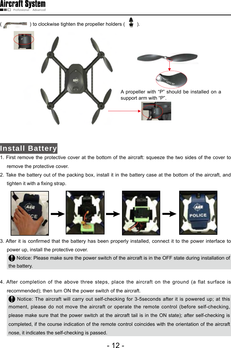
![- 36 -map type and click “OK”, and maps will be loaded automatically. If maps cannot be loaded normally after the ground station software is opened, please restart the software, connect to the network and try loading again. 2 Connect Serial Ports Connect serial port COM1 (ground station connects to the communication serial port) Find [COM1 Connect] on the toolbar; please select serial port COM1, and click “Connect”. A dialog box showing “Serial port opened” will pop up on the screen. Connect serial port COM2 (ground station connects to the joystick serial port) The dialog box of “Joystick Data” (as shown below) will pop up through Menu Tool Joystick Data. Select serial port COM2 and click “Connect” to connect the joysticks which are used to control the aircraft. Check “Send joystick data”; the progress bars will have corresponding indications when the joysticks are turned.. Serial port COM2 is used to receive data from joysticks connected to PC and then send the data to the aircraft via serial port COM1. Therefore, before connection of serial port COM2, please conrm that serial port COM1 has been connected. In case of any error in connection of serial ports, click “Close” on the toolbar and carry out reconnection. Calibration](https://usermanual.wiki/AEE-Technology/AEED0100001/User-Guide-2442982-Page-39.png)
![- 38 -this moment, the map will locate to the current position of the aircraft.After the ground station software is started, the default position displayed on the map is the last added position.As to undesired positioning information, you can also delete it by clicking “Delete” after selecting the location name. The ground station software has the ofine positioning function. Notice: 1. Maps of Google Satellite and Google Earth for the same area are not universal; please add maps separately.2. To use the ofine positioning function, please download and back up maps in advance.Add Waypoint Method 1: Add a waypoint, please directly double-click the position where you want to add a waypoint on the map.Method 2: Click [Add Waypoint] in the Flight Mission Editor, and then click the position where you want to add a waypoint on the map to add a waypoint. It is better to add the first waypoint near home point to prevent the aircraft from colliding with obstacles due to excessive obliquity of the aircraft route during its ascending. Add all the desired waypoints with the same method. After adding the waypoints, you can view the following information of waypoints on the map: Horizontal projection distance between two waypointsAir routeIndex number of waypoint Color of air route before editing is nished: Red: Abnormal White: Normal Hidden air route: Abnormal Notice: Only Google Earth hints abnormality in air route altitude; Google Satellite does not have such hint, so the air route altitude should be judged by yourself. Edit Waypoint After adding a new waypoint, you can continue to edit the waypoint.](https://usermanual.wiki/AEE-Technology/AEED0100001/User-Guide-2442982-Page-41.png)
![- 39 - Notice: After selection, the color of waypoint icon changes to green , indicating this waypoint is selected and can be edited. Change waypoint position: Method 1: Use the left mouse button to drag the waypoint to the desired position. Method 2: Edit longitude and latitude in the Flight Mission Editor. Input the desired longitude and latitude in the corresponding attribute values, then the waypoint will automatically move to the corresponding position. Change altitude, speed and hold time of waypoint Input the desired gures in the corresponding attribute values to change the altitude, speed and hold time of the waypoint. Notice: To edit the position and altitude of a waypoint, please make sure altitudes of all waypoints are applicable for the current terrain. Please see the description in the section of “Add Waypoint” for details. 5 Finish Task Editing Click [Finish Editing] in the Flight Mission Editor to finish flight mission editing, and all waypoint projection lines change to green:](https://usermanual.wiki/AEE-Technology/AEED0100001/User-Guide-2442982-Page-42.png)
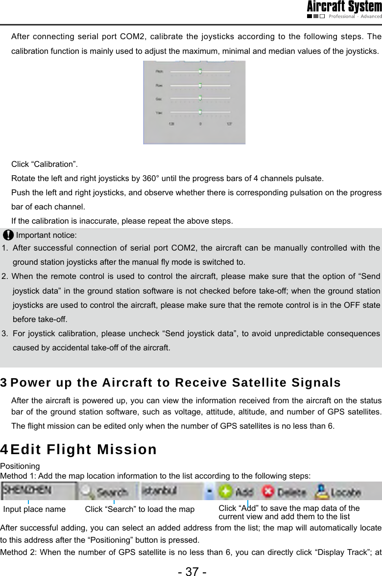
![- 40 -6 Upload Mission After finishing waypoint editing, click [Upload Mission] to upload the current flight mission to the aircraft. 7 Download Mission After the mission is successfully uploaded, click [Download Mission] to verify if the mission uploaded is correct; the following dialog box will pop up after “Download Mission” is clicked: Select “Yes” to save the current ight mission; select “No” to exit without saving. Save Flight Mission After nishing ight mission editing, you can save this ight mission according to the following steps: Step 1: You can save the currently edited ight mission through Menu File Save Mission, or the button on the Taskbar. The following dialog box will pop up in the ground station software:](https://usermanual.wiki/AEE-Technology/AEED0100001/User-Guide-2442982-Page-43.png)
![- 42 - 1) During outdoor ight, please make sure that the GPS signal strength indicator is no less than 6. 2) Check if the indications of the heading indicator and the attitude indicator are consistent with the current status of the aircraft; in case of any inconsistence, please contact us immediately. 9 Display Track / Clear Track 1) After starting the aircraft, click “Display Track” to display the real-time ight track of the aircraft during its ying along the air route (Fig. 1); if “Display Track” is not clicked, the real-time ight track of the aircraft will not be displayed (Fig. 2).2) When “Clear Track” is clicked after track is displayed, the current real-time ight track of the aircraft will be cleared (Fig. 2).(Fig.1) (Fig.2)10View Locking/Switching Function After track display, the map interface will automatically enter the view locking state. If [Lock View] is clicked, the view will be unlocked and you then can move the map. Click this button again to lock up the view. In the view locking mode, the map view will move as the aircraft position moves; in the view unlocking mode, the map view has no change. 11 Auto Take-off1) Before take-off, rst make sure the requirements on auto take-off are satised. See the instructions in the section of “Safety Precautions” for details. 2) After using the ground station to manually start the aircraft, turn the manual/auto switch of the ground station to the auto mode. 3) Click [Auto Take-off] on the toolbar; the aircraft will hover after ascending to an altitude of about 20m. 12 Auto Fly / Fly to the Designated Waypoint (Fly to) 1) Auto Fly Click [Auto Fly], and the aircraft will automatically y along the preset air route; the aircraft will hover after reaching the last waypoint. 2) Fly to the Designated Waypoint (Fly to)](https://usermanual.wiki/AEE-Technology/AEED0100001/User-Guide-2442982-Page-45.png)
![- 43 - Select the waypoint you want to y to in the Flight Mission Editor (the color of the selected waypoint is green); then click [Fly to] on the toolbar, and the aircraft will y to this waypoint; after reaching this waypoint, the aircraft will hover. Only one target waypoint can be added every time. 3) Edit Flight Mission in the Air You can continue to edit the flight mission after the aircraft enters the hover state. The following operations can be realized:a Continue to edit the ight mission; click [Edit Waypoint] to continue to add waypoints and edit waypoint information; click [Finish Editing] after editing is completed (at this moment, it is not needed to clear the ight mission; you can directly upload the current mission to overwrite the existing mission in the aircraft). Click [Download Mission] to ensure the mission is correct and then execute the action of [Auto Fly]. b The action of [Fly to] can be executed, as shown in Step 2 (at this moment, missions saved in the aircraft still exist). c Click [Clear Mission] to clear the ight missions in the aircraft and the content of missions shown on the map; at this moment, if [Auto Fly] is clicked, the aircraft will stay in the hover state. Before the aircraft executes the Auto Fly command, please rst download the mission to verify if the ight mission uploaded to the aircraft is correct. 13 Go Home If [Go Home] is clicked during flight or after the aircraft enters the hover state, the aircraft will automatically return and hover over the take-off position. The altitude of the homeward course is the altitude of the last waypoint. 14Landing Click [Auto Landing] after the aircraft returns, and the aircraft will automatically land vertically. 1) There might be minor difference between the landing position and the take-off position.2) To avoid unpredictable consequences, do not randomly click “Auto Landing” in the course of ight. 3) To close the ground station, please rst shut it down normally and then turn off the main power switch. 15One-button Auto Fly Before ight, please rst check if the requirements for One-button Auto Fly are satised (the throttle is in the lowest position; the Manual/Auto switch is in the Auto mode; at least one waypoint is uploaded), and refer to the descriptions in “Precautions”; Make sure ALL requirements for One-button Auto Fly are satised.](https://usermanual.wiki/AEE-Technology/AEED0100001/User-Guide-2442982-Page-46.png)
![- 44 - Place the aircraft in a horizontal posion (do not place the aircraft on a sloped ground for take-off); the “One-button Auto Fly” button will be lightened and become effective only after adding waypoints, uploading waypoint and downloading-waypoint-for-verification have been carried out in the ground stationsoftware. when the “One-button Auto Fly” button on the toolbar is clicked, the aircraft will fulll the entire ight mission, including Startup the Aircraft, Auto Take-off, Route Flight, Go Home, and Landing. 1.The “One-button Auto Fly” button on the toolbar can be clicked only when the requirements for One-button Auto Fly are all satised; otherwise, the aircraft will not execute the command. 2.The aircraft should be placed horizontally to avoid unnecessary troubles. 3.In the process of going home and landing, the status of the aircraft should be observed at all times; in case of any abnormality, switch to the manual control in time to ensure safe operation of the aircraft.Video Management Window Function of the Ground Station SoftwareThe aircraft starts automatic video recording after startup; enter the tab of Video Management Window of the ground station, then click [Preview] to view the real-time video sent back by the aircraft. 1 2 3 4 5 6 7 8 911101 Local Video Recording In local recording, the ground station saves the video recording sent back by the aircraft to local memory. Click “Local Video Recording” on the toolbar to start recording; after recording is nished, click [Stop] to end recording and save the video le to the ground station computer. The system will automatically pop up a dialog box indicating the save path of the video le:](https://usermanual.wiki/AEE-Technology/AEED0100001/User-Guide-2442982-Page-47.png)
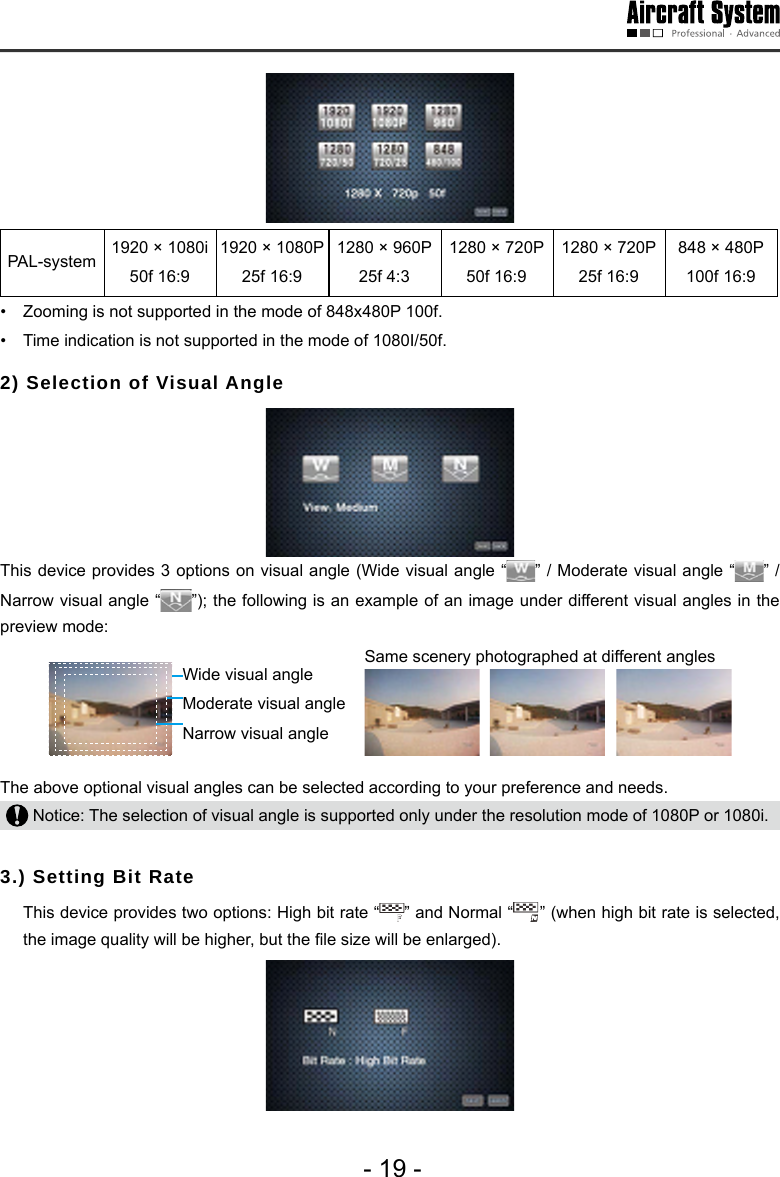
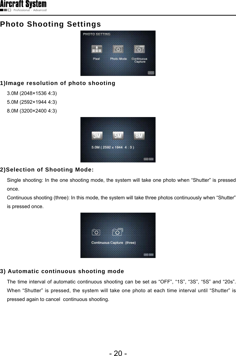
![- 45 -2 Screenshot Click [Screenshot] on the toolbar to capture the current screen and save the screenshot le to the ground station computer; the system will automatically pop up a dialog box indicating the image store path: 3 Zoom in / Zoom out Click “Zoom in” / “Zoom out” to adjust the focal length of the airborne camera.4 Airborne Video Recording Click [Airborne Video Recording] button on the toolbar to start video recording of the airborne camera; during recording, the button will remain selected; click the button again to stop recording and it will bounce up. 5 Airborne Photo shooting (Support Snapshot) - Click [Airborne Photo Shooting] on the toolbar to take a photo.- Click [Airborne Photo Shooting] during video recording to realize the snapshot function. Snapshot is not supported in the resolution modes of 1080i/50f, 720P/50f and 480P/100f. Notice: The functions of zoom in, zoom out, airborne video recording and photo shooting can also be realized via corresponding buttons on the ground station panel. 6 Video Recording Setting Parameters of the aircraft camera can be set:](https://usermanual.wiki/AEE-Technology/AEED0100001/User-Guide-2442982-Page-48.png)
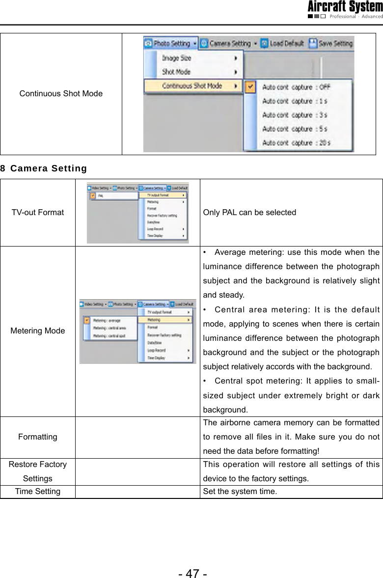
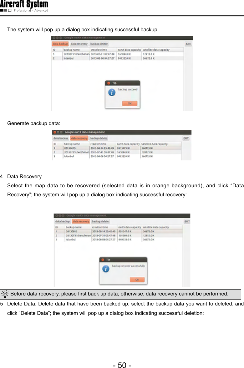
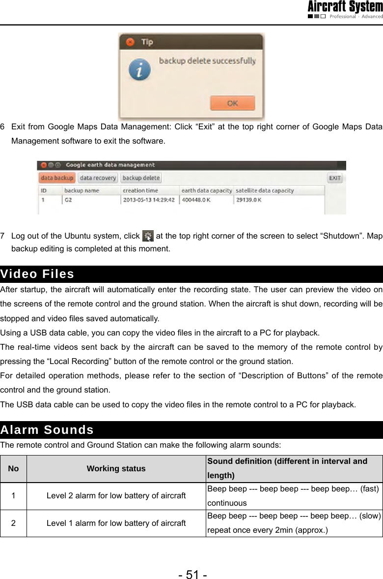
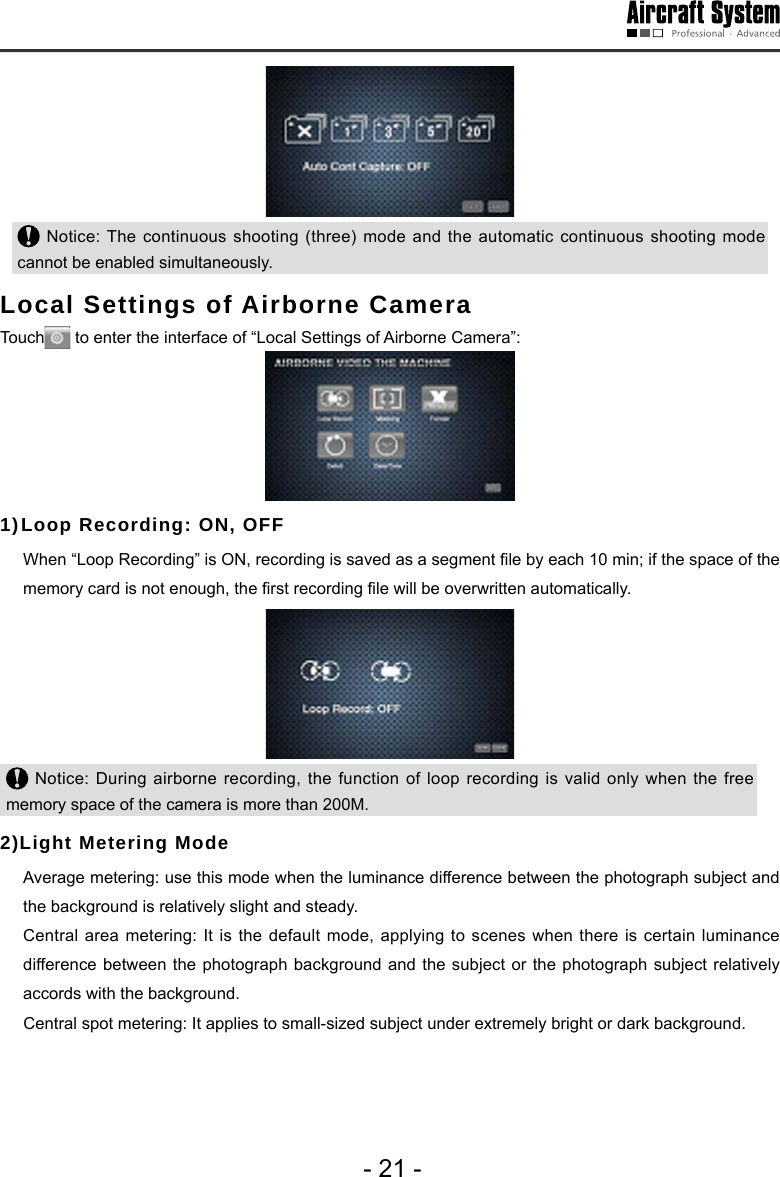
![- 48 -Loop Recording When “Loop Recording” is ON, recording is saved as a segment le by each 10 min; if the space of the memory card is not enough, the rst recording le will be overwritten automatically.Time Indication Show or hide time display. 9 Loading Setting Click [Loading Settings] on the toolbar to load the current settings of the airborne camera. 10 Save Settings Click [Save Settings] on the toolbar to save the current settings of the airborne camera. Important notice: Settings will take effect only when [Save Settings] is clicked after a setting is modied. 11 Angle of Airborne Camera The angle of the airborne camera can be adjusted within the range of 0-105°. Map Backup The ground station system adopts the data platforms of Google Earth and Google Satellite Map. During map browsing, the system will automatically save the data of browsed maps to the system so that you can view the browsed maps ofine. However, the map storage capacity of Google Earth is limited (the maximum capacity of Google Earth is 2G and that of Google Satellite Maps is 1G). When the capacity of browsed map data exceeds this limit, the old map data will be lost. In addition, data loss may be caused by misoperation, which will result in the failure of access to Google Earth data platform after the ground station system is opened. To avoid loss of map data, data backup software is provided in the Ubuntu operating system. This software provides the following three functions: 1. Save map data; during use of the ground station, the user can save the map data according to area partition and date. Note: The data backup le should not exceed the map capacity limit (Google Earth: 2GB; Google Satellite Maps: 1GB).2. Restore map data; in case maps cannot be loaded due to data loss during use, if access to Internet is also not available, the user can enter this software to restore map data.3. Delete: Delete undesired backup data.](https://usermanual.wiki/AEE-Technology/AEED0100001/User-Guide-2442982-Page-51.png)