AEE Technology AEED0200001 Unmanned Aircraft Systems (Ground Control Station) User Manual
Shenzhen AEE Technology CO., LTD. Unmanned Aircraft Systems (Ground Control Station) Users Manual
UserManual.wiki
>
AEE Technology
>
AEED0200001 User Manual
Users Manual
Navigation menu
Upload a User Manual
Namespaces
Wiki Guide
HTML
PDF
Info
Views
User Manual
Discussion / Help
Navigation
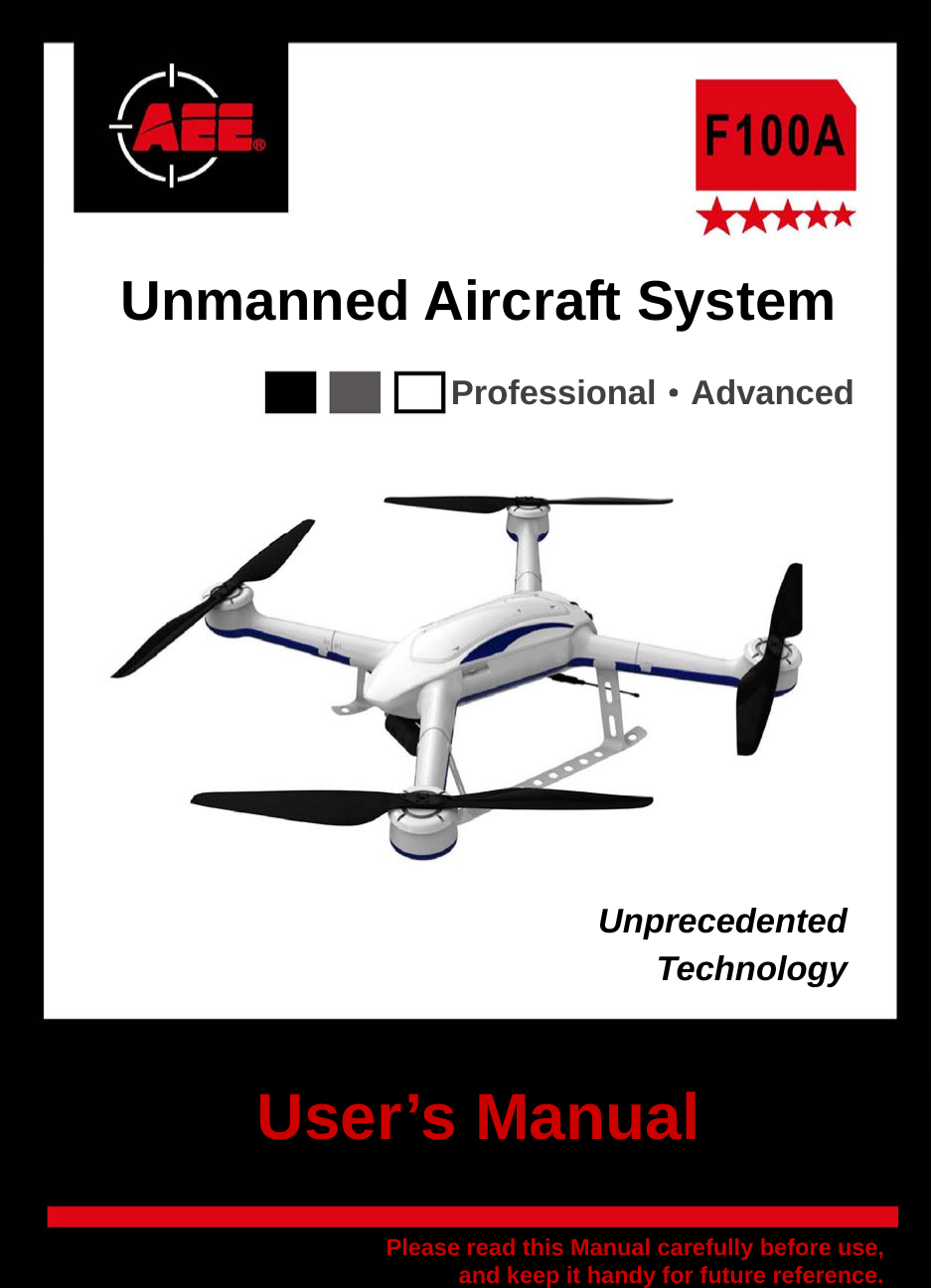
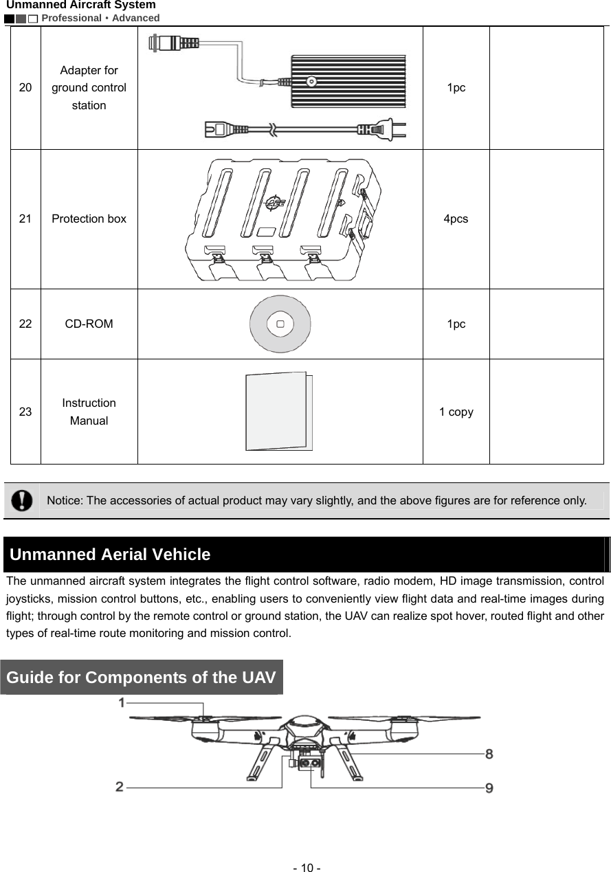
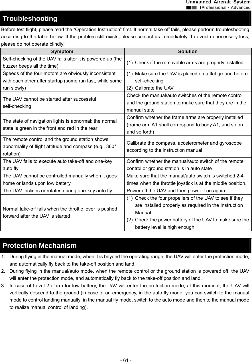
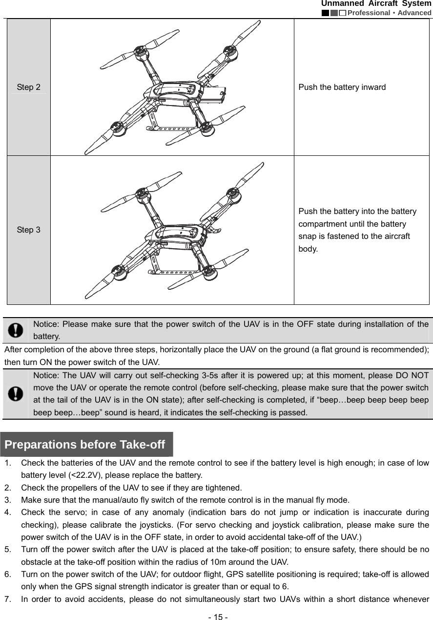
![Unmanned Aircraft System Professional·Advanced - 11 - [1] Motor [2] PTZ [3] Removable arm A1 [4] Frame arm A1 [5] Frame arm B2 [6] Removable arm B2 [7] Power key [8] Undercarriage [9] Airborne camera [10] Propeller [11] Removable arm B1 [12] Frame arm B1 [13] Frame arm A2 [14] Removable arm A2 [15] Power indicator [16] Battery plug switch Configuration of F100 main unit system](https://usermanual.wiki/AEE-Technology/AEED0200001/User-Guide-2557441-Page-15.png)
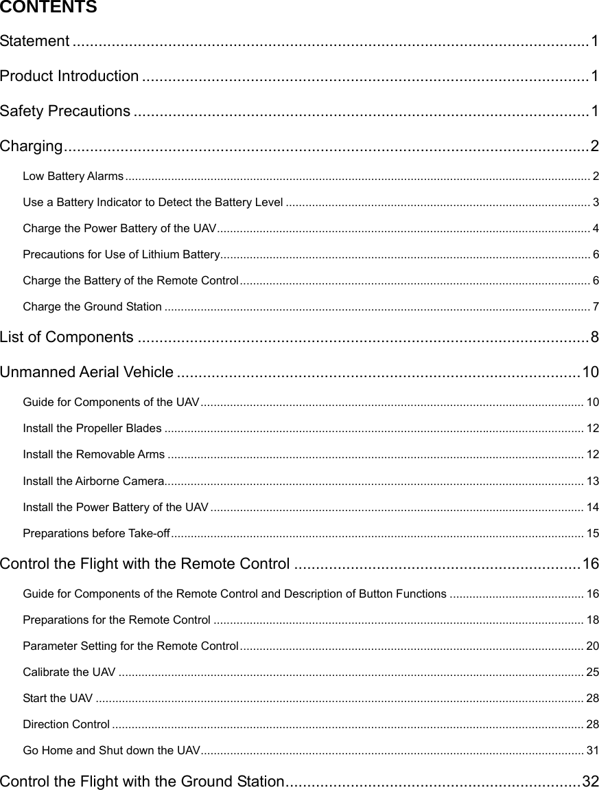
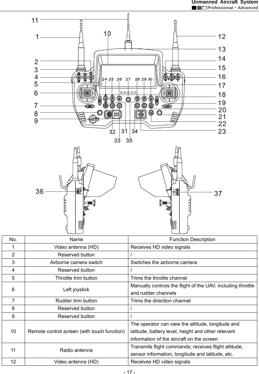
![Unmanned Aircraft System Professional·Advanced - 16 - possible. 8. Before take-off, please make sure that the video and radio antennas have been properly installed to avoid influence on the flight or the video receiving distance, or damage to the UAV or the transmitter module inside the remote control. 9. When the remote control is used to control the UAV, please make sure that the option of “Send Joystick Data” in the ground station software is not checked before take-off; when the ground station joystick is used to control the UAV, please make sure that the remote control is in the OFF state before take-off. Control the Flight with the Remote Control The remote control is specially developed for the unmanned aircraft system to make it convenient for controlling the flight of the UAV. The remote control can independently control the flight of the UAV, and can display the flight status of the UAV and the real-time images from the airborne camera simultaneously. Guide for Components of the Remote Control and Description of Button Functions The components of the remote control and the button functions are shown as follows: [1] Remote control handle [2] Battery cover snap [3] Battery cover [4] USB port [5] HDMI port [6] Adapter port [7] Reserved port [8] AV port](https://usermanual.wiki/AEE-Technology/AEED0200001/User-Guide-2557441-Page-20.png)
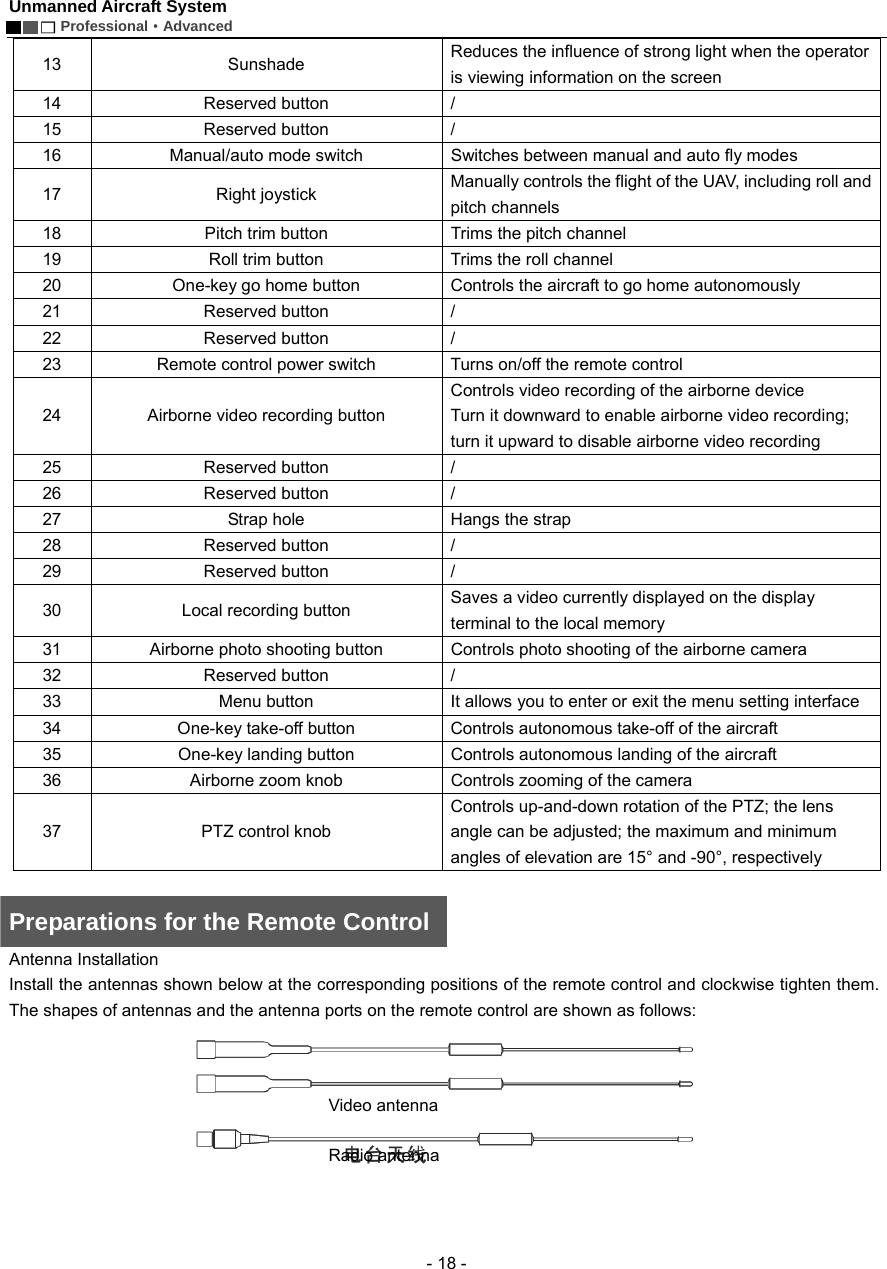
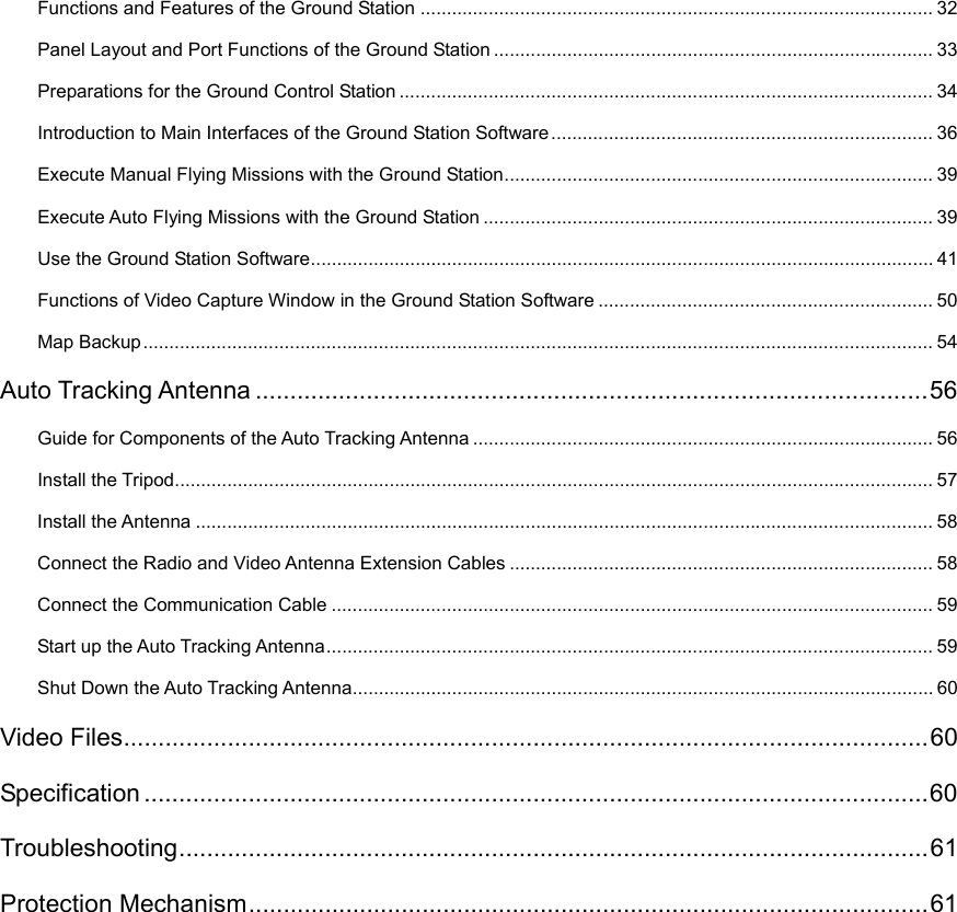
![Unmanned Aircraft System Professional·Advanced - 20 - Parameter Setting for the Remote Control The information displayed on the screen upon power-on is shown as follows: Press “M” to enter the “Setting” interface of the remote control: Indication of airborne video recording status Heading indicator Indication of local recording status of remote control Indication of battery level of UAV Indication of GPS signal strengthIndication of speedvalueLongitude and latitudeof take-off positionThrottle trimCourse trim Indication of camera clockRoll trimPitch trimLongitude and latitude of current position Indication of height Horizon instrument (indication of roll andpitch attitudes) Indication of battery level of remote control批注[e1]:下图跟提供的英文界面图有些区别,请确认是否替换](https://usermanual.wiki/AEE-Technology/AEED0200001/User-Guide-2557441-Page-24.png)
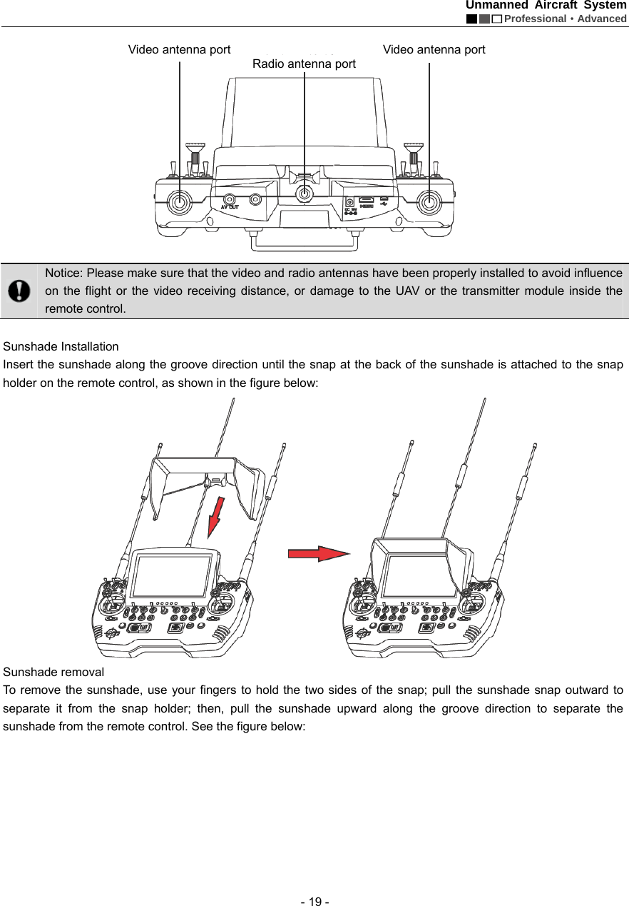
![Unmanned Aircraft System Professional·Advanced - 21 - * * Servo Checking Check if the functions of joysticks, fly mode switch and PTZ control knob on the remote control are normal through “Servo Checking”. Here are the steps of servo checking: 1) Press “M” to enter the “Setting” interface the remote control. 2) Touch “Servo Checking” to enter the setting interface: 3) At this moment, turn the left and right joysticks by the maximum angle possible, toggle the fly mode switch and rotate the PTZ control knob, and the relevant indication bars will pulsate correspondingly; the functions of roll, pitch, throttle, course, auto fly switch and angle adjustment of airborne camera can be checked. Notice: Servo checking must be carried out before take-off; before servo checking, please make sure that the power switch of the UAV is in the OFF state, in order to avoid accidental startup of the UAV. * Joystick Calibration Touch “[Start]” for joystick calibration in the “Servo Checking” interface in the above step; turn the left and right joysticks for 5-10 circles by 360° to enter the state of joystick calibration; indication bars of roll, pitch, throttle and course will pulsate correspondingly; click “DONE” to finish the calibration process. Carry out servo checking after completion of calibration; it is OK if servo checking shows normal result; otherwise, recalibration is required. Notice: Before joystick calibration, please make sure that the power switch of the UAV is in the OFF state, in order to avoid accidental startup of the UAV. * Airborne Camera Setting Touch to enter the following interface: 批注[e2]:下图跟提供的英文界面图有些区别,请确认是否替换批注[e3]:下图跟提供的英文界面图有些区别,请确认是否替换](https://usermanual.wiki/AEE-Technology/AEED0200001/User-Guide-2557441-Page-25.png)
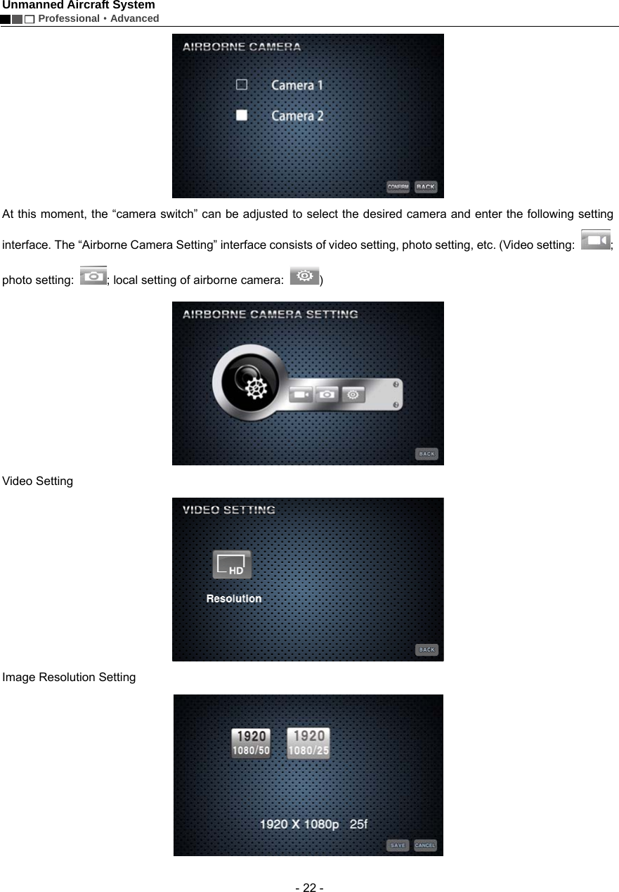
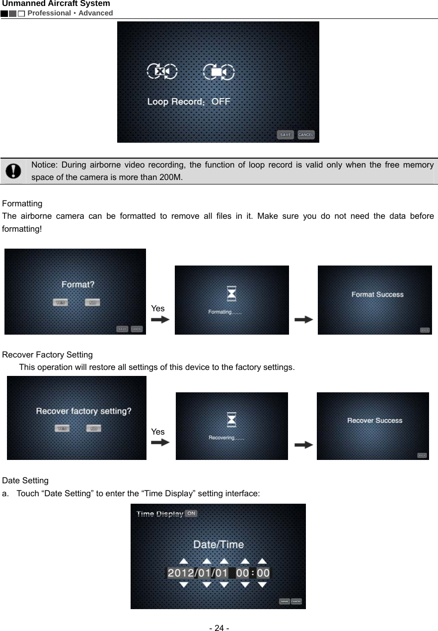
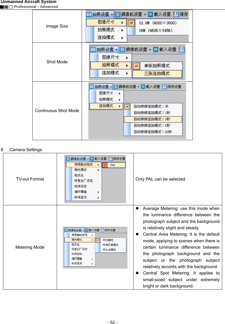
![Unmanned Aircraft System Professional·Advanced - 23 - PAL-system 1920×1080 50f 16:9 1920×1080 25f 16:9 Photo Setting Photo Resolution 12.0M (4000×3000 4:3) default 16.0M (4608×3456 4:3 ) Local Setting of Airborne Camera Touch to enter the “Local Setting of Airborne Camera” interface: Loop Record: ON, OFF No matter whether “Loop Record” is ON or OFF, recording is saved as a segment file by each 10 min. When “Loop Record” is ON, if the space of the memory card is not enough, the first segment of recording file will be overwritten automatically. 批注[e4]:提供的英文界面图中没有找到下图批注[e5]:下图原稿中是“开”,而提供的英文界面图中是 OFF,是否可以替换?](https://usermanual.wiki/AEE-Technology/AEED0200001/User-Guide-2557441-Page-27.png)
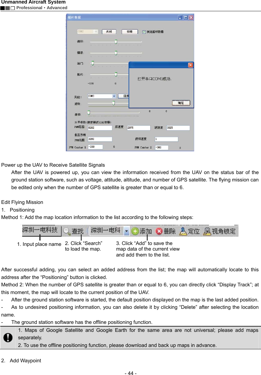
![Unmanned Aircraft System Professional·Advanced - 42 - If maps cannot be loaded normally after the ground station software is opened, please restart the software, connect to the network and try loading again. Connect Serial Ports 1. Connect serial port COM1 (ground station connects to the communication serial port) Find [COM1 Connect] on the toolbar; please select serial port COM1, and click “Connect”. A dialog box showing “Serial port opened” will pop up on the screen. 2. Connect serial port COM2 (ground station connects to the joystick serial port) The dialog box of “Joystick Data” (as shown below) will pop up through ->. Menu ->. Tool ->. Joystick Data. Select serial port COM2 and click “Connect” to connect the joysticks which are used to control the UAV. ->. Check “Send Joystick Data”; the progress bars will have corresponding indications when the joysticks are turned.. In case of any error in connection of serial ports, click “Close” on the toolbar and carry out reconnection. Joystick Calibration: After connecting serial port COM2, you can calibrate the joysticks according to the following steps. The calibration function is mainly used to adjust the maximum, minimal and median values of the joysticks.](https://usermanual.wiki/AEE-Technology/AEED0200001/User-Guide-2557441-Page-46.png)
![Unmanned Aircraft System Professional·Advanced - 43 - 1) Click “Calibration”. 2) Rotate the left and right joysticks by 360° until the progress bars of 4 channels pulsate. 3) Push the left and right joysticks, and observe whether there is corresponding pulsation on the progress bar of each channel. 4) If the calibration is inaccurate, please repeat the above steps. Important: 1. After successful connection of serial port COM2, the UAV can be manually controlled with the ground station joysticks after the manual fly mode is switched to. 2. When the remote control is used to control the UAV, please make sure that the option of “Send Joystick Data” in the ground station software is not checked before take-off; when the ground station joysticks are used to control the UAV, please make sure that the remote control is in the OFF state before take-off. 3. For joystick calibration, please uncheck “Send Joystick Data”, in order to avoid unpredictable consequences caused by accidental take-off of the UAV. 3. Connect serial port COM3 (auto tracking antenna connection serial port) Select COM3 [Antenna: Connect]; click “Connect”, and the dialog box showing “Serial port opened” will pop up on the screen.](https://usermanual.wiki/AEE-Technology/AEED0200001/User-Guide-2557441-Page-47.png)
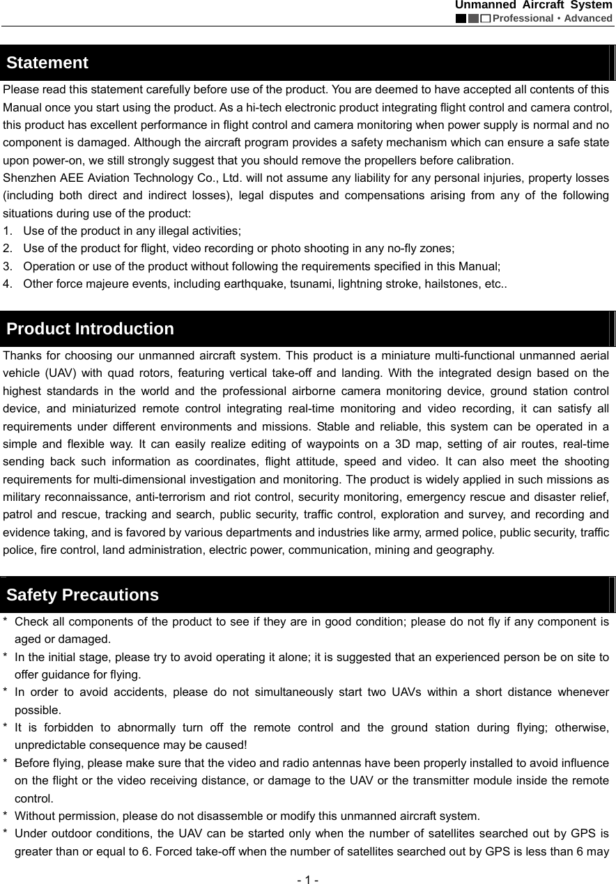
![Unmanned Aircraft System Professional·Advanced - 45 - Method 1: Directly double-click the position where you want to add a waypoint on the map to add a waypoint.. Method 2: Click [Add Waypoint] in the Flying Mission Editor, and then click the position where you want to add a waypoint on the map to add a waypoint. It is better to add the first waypoint near home point to prevent the UAV from colliding with obstacles due to excessive obliquity of the UAV route during its ascending. Add all the desired waypoints with the same method. After adding the waypoints, you can view the following information of waypoints on the map: - Color of air route before editing is finished: Red: Abnormal White: Normal Hidden air route: Abnormal Notice: Only Google Earth hints abnormality in air route altitude; Google Satellite does not have such hint, so the air route altitude should be judged by yourself. 3. Edit Waypoint After adding a new waypoint, you can continue to edit the waypoint. Notice: After selection, the color of waypoint icon changes to green , indicating this waypoint is selected and can be edited. 1) Change waypoint position: Method 1: Use the left mouse button to drag the waypoint to the desired position. Method 2: Edit longitude and latitude in the Flying Mission Editor. Input the desired longitude and latitude in the corresponding attribute values, then the waypoint will automatically move to the corresponding position. Air route Horizontal projection distance between two waypoints Index number of waypoint](https://usermanual.wiki/AEE-Technology/AEED0200001/User-Guide-2557441-Page-49.png)
![Unmanned Aircraft System Professional·Advanced - 46 - 2) Change altitude, speed and hold time of waypoint Input the desired figures in the corresponding attribute values to change the altitude, speed and hold time of the waypoint. Notice: To edit the position and altitude of a waypoint, please make sure that altitudes of all waypoints are applicable for the current terrain. Please see the description in the section of “Add Waypoint” for details. Finish Mission Editing Click [End Edit] in the Flying Mission Editor to finish flying mission editing, and all waypoint projection lines change to green: Upload Mission After finishing waypoint editing, click [Upload] to upload the current flying mission to the UAV. Download Mission After the mission is successfully uploaded, click [Download] to verify if the mission uploaded is correct; the following dialog box will pop up after “Download” is clicked: Select “Yes” to save the current flying mission; select “No” to exit without saving. Save Flying Mission](https://usermanual.wiki/AEE-Technology/AEED0200001/User-Guide-2557441-Page-50.png)

![Unmanned Aircraft System Professional·Advanced - 48 - 1) After successful connection of the ground station to joystick serial port COM2, check the option of “Send Joystick Data”. 2) Switch to the manual fly mode. 3) For the startup method, please see the description in the section of “Start the UAV with the Remote Control”. 1) During outdoor flight, please make sure that the numeric value on the GPS signal strength indicator is greater than or equal to 6. 2) Check if the indications of the heading indicator and the attitude indicator are consistent with the current status of the UAV; in case of any inconsistence, please contact us immediately. Display Track / Clear Track 1) After starting the UAV, click “Display Track” to display the real-time flight track of the UAV during its flying along the air route (Fig. 1); if “Display Track” is not clicked, the real-time flight track of the UAV will not be displayed (Fig. 2). 2) When “Clear Track” is clicked after track is displayed, the current real-time flight track of the UAV will be cleared (Fig. 2). View Locking/Switching Function After track display, the map interface will automatically enter the view locking state. If [Lock View] is clicked, the view will be unlocked and you then can move the map. Click this button again to lock up the view. In the view locking mode, the map view will move as the position of the UAV moves; in the view unlocking mode, the map view has no change. Auto Take-off 1) Before take-off, first make sure that the requirements on auto take-off are satisfied. See the instructions in the section of “Safety Precautions” for details. Auto take-off can be executed only when the requirements are satisfied. 2) Connect the ground station to serial port COM2, and check “Send Joystick Data”; push the throttle joystick to the lowest position. 3) Click [Auto Take-off] on the toolbar; the UAV will hover after automatically ascending to an altitude of about 20m. Auto Fly / Fly to 1) Auto Fly (Fig. 1) (Fig. 2)](https://usermanual.wiki/AEE-Technology/AEED0200001/User-Guide-2557441-Page-52.png)
![Unmanned Aircraft System Professional·Advanced - 49 - Click [Auto Fly], and the UAV will automatically fly along the preset air route; the aircraft will hover after reaching the last waypoint. 2) Fly to Select the waypoint you want to fly to in the Flying Mission Editor (the color of the selected waypoint is green); then click [Fly to] on the toolbar, and the UAV will fly to this waypoint; after reaching this waypoint, the aircraft will hover. Only one target waypoint can be added every time. 3) Edit Flying Mission in the Air You can continue to edit the flying mission after the UAV enters the hover state. The following operations can be realized: a. Continue to edit the flying mission; after clicking [Edit], you can continue to add waypoints and edit waypoint information; click [End Edit] after editing is completed (at this moment, it is not needed to clear the flying mission; you can directly upload the current mission to overwrite the existing mission in the UAV). Click [Download] to ensure that the mission is correct and then execute the action of [Auto Fly]. b. The action of [Fly to] can be executed, as shown in Step 2 (at this moment, missions saved in the UAV still exist). c. Click [Clear] to clear the flying missions in the UAV and the content of missions shown on the map; at this moment, if [Auto Fly] is clicked, the UAV will stay in the hover state. Before the UAV executes the “Auto Fly” command, please first download the mission to verify if the flying mission uploaded to the UAV is correct. Go Home If [Go Home] is clicked during flight or after the UAV enters the hover state, the UAV will automatically return and hover over the take-off position. The altitude of the homeward course is the altitude of the last waypoint. Auto Landing Click [Auto Landing] after the UAV returns, and the UAV will automatically land to the take-off position. 1) There might be minor difference between the landing position and the take-off position. 2) To avoid unpredictable consequences, please do not randomly click “Auto Landing” in the course of flight. 3) To close the ground station, please first shut it down normally and then turn off the main power switch. One-key Auto Fly Before take-off, please make sure all requirements for one-key auto fly are satisfied (the throttle is at the lowest position; the manual/auto fly switch is turned to the auto mode; at least one waypoint is uploaded). Please see the section of “Precautions”. One-key auto fly can be executed only when all requirements are satisfied. Place the UAV on a horizontal surface (do not place it on a sloped ground for take-off). Only after adding waypoints to maps in the ground station software, uploading waypoints and downloading waypoints for verification will the “One-key Auto Fly” button light up and become effective. Click the “One-key Auto Fly” button on the toolbar; the UAV will finish the entire flying mission, including starting the UAV, auto take-off, routed flight, going home and landing. Notice! 1) Click the “One-key Auto Fly” button on the toolbar only after the requirements for one-key auto fly are satisfied. Otherwise, the UAV will not execute the command. 2) In order to avoid unnecessary troubles, the UAV should be placed on a horizontal surface for take-off. 3) Always observe the state of the UAV during its landing so that the UAV can be controlled manually in a](https://usermanual.wiki/AEE-Technology/AEED0200001/User-Guide-2557441-Page-53.png)
![Unmanned Aircraft System Professional·Advanced - 50 - timely manner in case of any abnormality in this process. Functions of Video Capture Window in the Ground Station Software The UAV starts automatic video recording after startup; enter the tab of Video Capture Window of the ground station; Click [Preview]; the window will display the real-time video sent back by the UAV. 1 Local Video Recording Click “Local Video Recording” on the toolbar to start recording; after recording is finished, click [Stop] to end recording and save the video file to the ground station computer. The system will automatically pop up a dialog box indicating the save path of the video file: 2 Screenshot Click [Screenshot] on the toolbar to capture the current screen and save the screenshot file to the ground station computer; the system will automatically pop up a dialog box indicating the image save path:](https://usermanual.wiki/AEE-Technology/AEED0200001/User-Guide-2557441-Page-54.png)
![Unmanned Aircraft System Professional·Advanced - 51 - 3 Zoom in / Zoom out Click “Zoom in” / “Zoom out” to adjust the focal length of the airborne camera. 4 Airborne Video Recording Click [Airborne Video Recording] on the toolbar to start video recording of the airborne camera; during recording, the button will remain selected; click the button again to stop recording and it will bounce up. 5 Airborne Photo Shooting 1) Click [Airborne Photo Shooting] on the toolbar to control the camera to take photos. 2) Click [Airborne Photo Shooting] during video recording to realize the snapshot function. Notice: The functions of zoom in, zoom out, airborne video recording and airborne photo shooting can also be realized via corresponding buttons on the ground station panel. 6 Video Setting Parameters of the UAV camera can be set: Resolution View Angle Bit Rate 7 Photo Setting](https://usermanual.wiki/AEE-Technology/AEED0200001/User-Guide-2557441-Page-55.png)
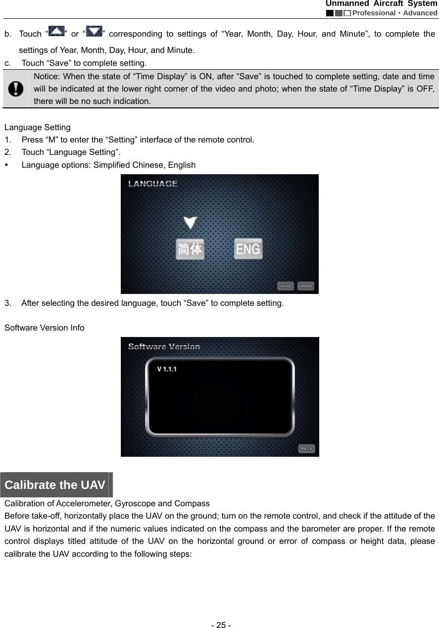
![Unmanned Aircraft System Professional·Advanced - 53 - Formatting The airborne camera memory can be formatted to remove all files in it. Make sure you do not need the data before formatting! Recover Factory Setting This operation will restore all settings of this system to the factory settings. Time Setting Set the system time. Loop Record No matter whether “Loop Record” is ON or OFF, recording is saved as a segment file by each 10 min. When “Loop Record” is ON, if the space of the memory card is not enough, the first segment of recording file will be overwritten automatically. Time Display Show or hide time display. 9 Load Setting Click [Load Setting] on the toolbar to load the current settings of the airborne camera.](https://usermanual.wiki/AEE-Technology/AEED0200001/User-Guide-2557441-Page-57.png)
![Unmanned Aircraft System Professional·Advanced - 54 - 10 Save Setting Click [Save Setting] on the toolbar to save the current settings of the airborne camera. Important: Settings will take effect only when [Save Setting] is clicked after a setting is modified. Map Backup The ground station system adopts the data platforms of Google Earth and Google Satellite. During map browsing, the system will automatically save the data of browsed maps to the system so that you can view the browsed maps offline. However, the map storage capacity of Google Earth is limited (the maximum capacity of Google Earth is 2G and that of Google Maps is 1G). When the capacity of browsed map data exceeds this limit, the old map data will be lost. In addition, data loss may be caused by misoperation, which will result in the failure of access to Google Earth data platform after the ground station system is opened. To avoid loss of map data, data backup software is provided in the Ubuntu operating system. This software provides the following three functions: 1 Save map data; during use of the ground station, the user can save the map data according to area partition and date. Note: The data backup file should not exceed the map capacity limit (Google Earth: 2G; Google Maps: 1G). 2 Restore map data; in case maps cannot be loaded due to data loss during use, if access to Internet is also not available, the user can enter this software to restore map data. 3 Delete: Delete undesired backup data. Important: Before use of map backup, first open the ground station GS software in the Windows system, and make sure that maps of Google Satellite and Google Earth have been downloaded and can be used. The backup operation steps are as follows: 1 Start up and select to enter the Ubuntu system (see the following figure): After opening the ground station system, select to enter the Ubuntu system in the “Select System” menu:](https://usermanual.wiki/AEE-Technology/AEED0200001/User-Guide-2557441-Page-58.png)
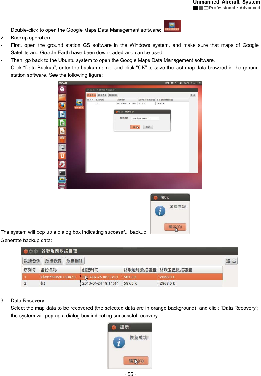
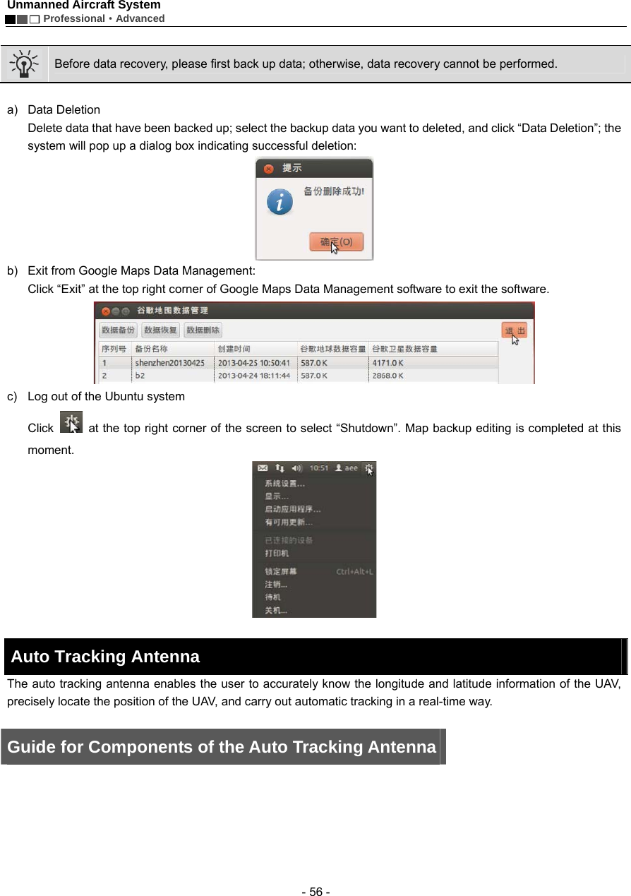
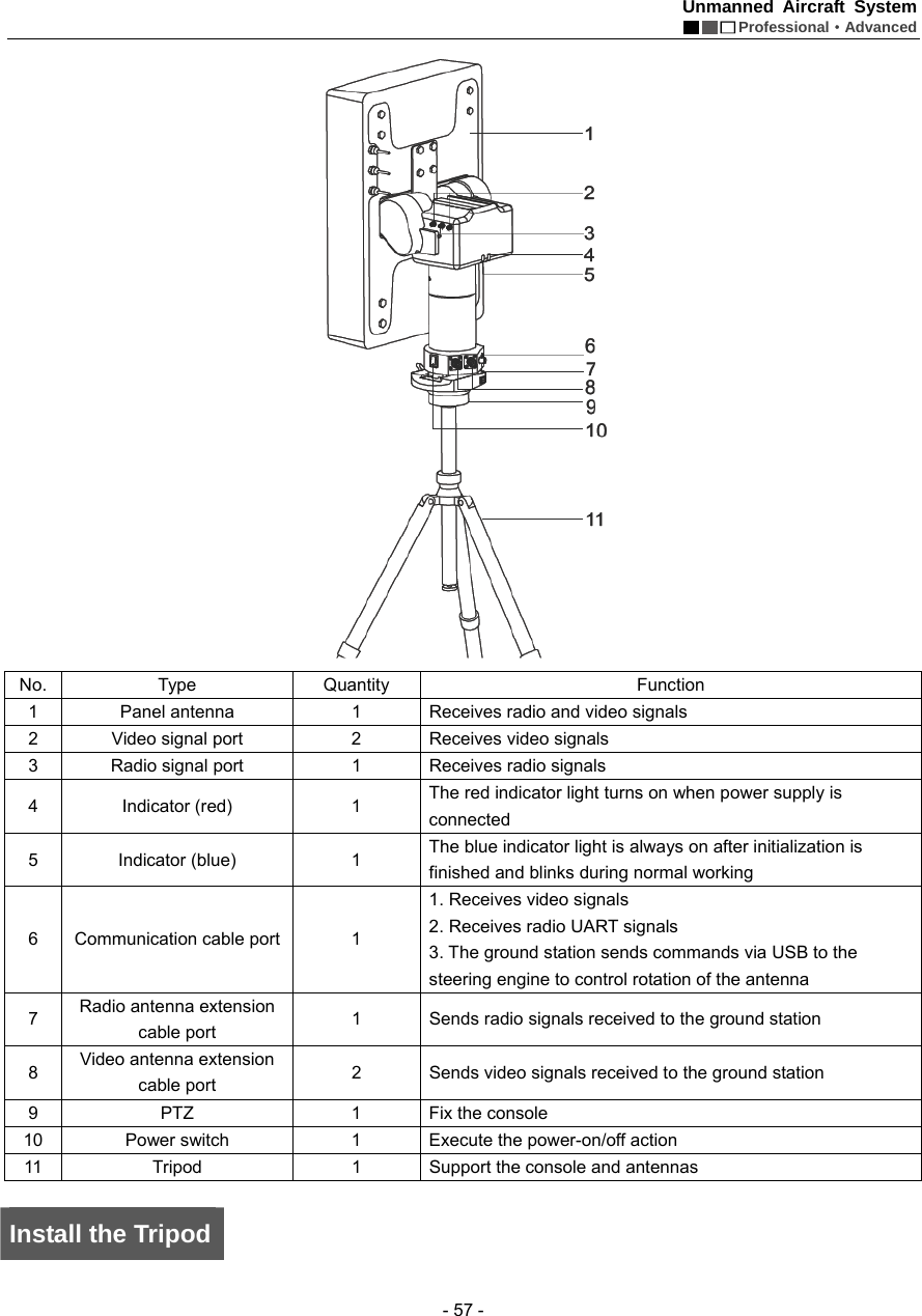
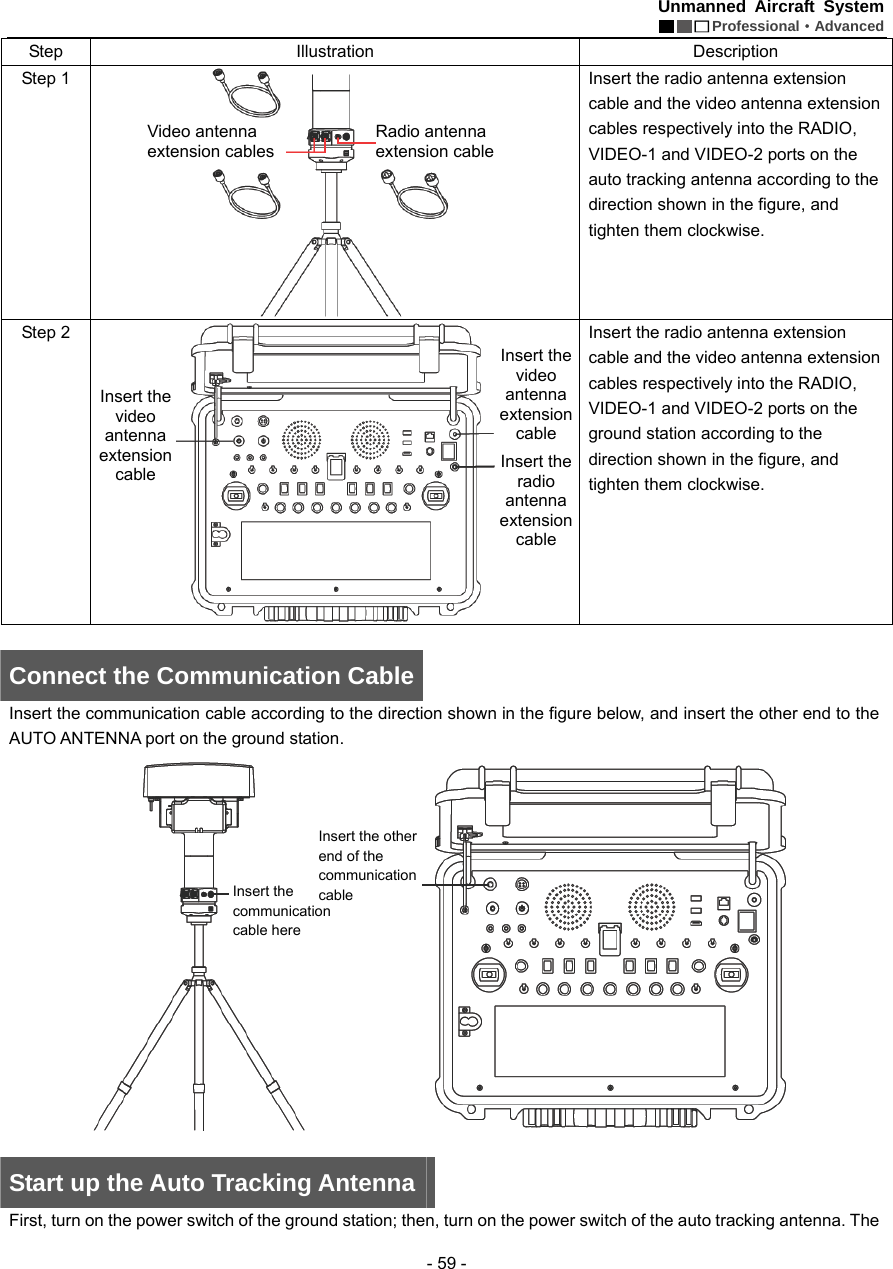
![Unmanned Aircraft System Professional·Advanced - 60 - red power indicator turns on, and the antenna begins initialization; the initialization is finished when the antenna faces south. As to the method for connecting the auto tracking antenna to the ground station software, please see the section of “Use the Ground Station Software — Auto Tracking Antenna Connection Serial Port” on Page 43. Notice: 1. When using the auto tracking antenna, please keep away from areas subjected to intense electromagnetic interference. 2. When connecting the auto tracking antenna to the ground station software, please first turn on the power switch of the auto tracking antenna and then open the ground station software. Shut Down the Auto Tracking Antenna First, close the ground station GS software; then, turn off the power switch of the auto tracking antenna, and disconnect the communication cable, radio antenna extension cable and video antenna extension cables. Warning: When disconnecting the communication cable of the auto tracking antenna, please first pull the aviation plug shell outward, and then pull out the plug. Video Files After startup, the UAV will automatically enter the video recording state. The user can preview the video on the screens of the remote control and the ground station. When the UAV is shut down, recording will be stopped and video files saved automatically. Using a USB data cable, you can copy the video files in the UAV to a PC for playback. The real-time videos sent back by the UAV can be saved to the memory of the remote control by pressing the “Local Recording” button of the remote control or the ground station. For detailed operation methods, please refer to the section of “Description of Buttons” of the remote control and the ground station. Specification Description Specification Fly mode Manual remote control, autonomous hover, autonomous route No-load take-off weight ≤7.8kg (with battery) Load capacity ≤4.5kg Endurance time 40min (20,000mAh battery) 30min (15,000mAh battery) Maximum cruising speed 15m/s (not suggested) Maximum remote control range 10km Maximum flying range 20km Flight altitude (relative altitude) Max. 3,000m Climbing speed ≥8m/s Normal take-off/landing wind speed Below Level 6 Working temperature -10°C ~ +50°C Working humidity 0% ~ 95%RH Storage temperature -20°C ~ +60°C Airborne camera HD camera with two-axis PTZ 批注[e6]:原稿:天线面朝南 方,初始化完毕。 是指天线面朝南方时,初始化完毕吗? 批注[e7]:原稿:P41译稿中该部分是在 43 页上](https://usermanual.wiki/AEE-Technology/AEED0200001/User-Guide-2557441-Page-64.png)