AEG Identifikationssysteme AREH5-1 RFID Reader User Manual Manual ARE H5 english 16
AEG Identifikationssysteme GmbH RFID Reader Manual ARE H5 english 16
UserManual.wiki
>
AEG Identifikationssysteme
>
AREH5 1 User Manual
user manual
Navigation menu
Upload a User Manual
Namespaces
Wiki Guide
HTML
PDF
Info
Views
User Manual
Discussion / Help
Navigation
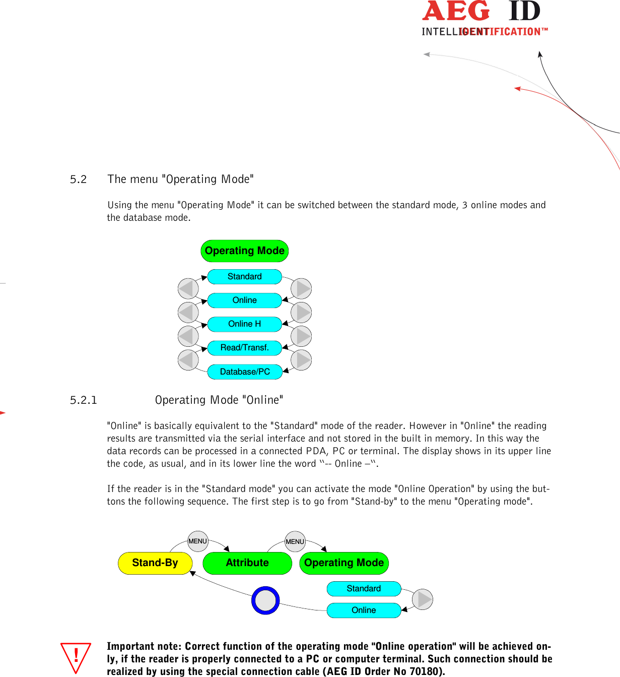
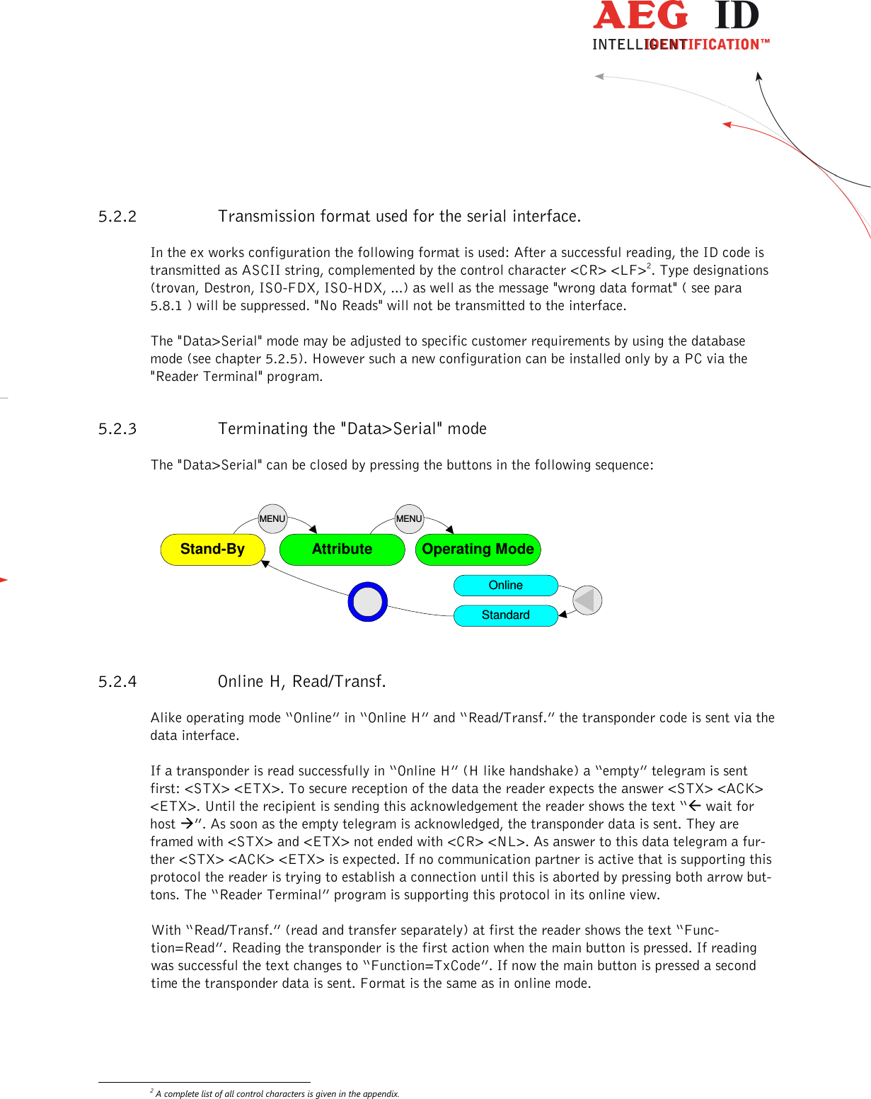
![--------------------------------------------------------------------------------15/31-------------------------------------------------------------------------------- !!5.2.5 The database mode The operating mode "Database/PC" is not an operating mode intended for reading transponders, but it is dedicated to the communication between the reader and a computer. In the database Mode the content of the database in the reader may be transferred to the PC and back again. This allows to process the data records in the PC, as well as to add further information such as text, for example. These operations will be performed in an easy way by using the "Reader Terminal" program (for Win-dows operation systems). It was developed by AEG ID to show the user the range of capabilities pro-vided by the database mode. All the steps necessary to set up communication between the ARE H5 handheld reader and a PC are presented in an "interactive" way. The "Reader Terminal" program al-lows a simple visualization of the data records, stored in the reader, and how they can be modified. Furthermore it allows to change the setting of certain parameter (see also chapter 6). The database mode is reached in the menu "Operating mode". Starting from "Stand-by" the buttons have to be pressed in the following sequence: AttributeStand-By Operating ModeMENUMENUStandardOnlineOnline HRead/Transf.Database/PC Important note: Correct function of the operating modes "Database/PC" or "Data->Serial" will be achieved only, if the reader is connected properly to a computer. Such connection may be realized either by using the special connection cable or via Bluetooth or Infrared link. Make sure that the terminal is set for the specified data format (see ARE H5 Specifications in chap-ter 7.1 and 7.9 ), especially if it is intended to use with individually made application software. The ARE H5 handheld reader does not switch off automatically, when it is used in the database mode. The user has to take care that the reader is set back to standard mode or online opera-tion after he has completed the configuration changes; otherwise the batteries may be dis-charged in a destructive way. Normally the database mode is terminated from the PC. As an alternative it can be terminated by simultaneously pressing the buttons "arrow right" and "arrow left". The specification of the transfer protocol used in the database mode is given in chapter 0 as reference [1]. It is intended for those users, who will generate their own specific application software.](https://usermanual.wiki/AEG-Identifikationssysteme/AREH5-1/User-Guide-3221770-Page-15.png)
![--------------------------------------------------------------------------------31/31-------------------------------------------------------------------------------- 7.10 Documentation, References [1]: “Data exchange Protocol for the ARE H5” describes all available commands, parameters, format of the transmission protocol, error codes and control characters, which are used in the "Database mode" of the ARE H5. [2]: “Operating instruction for the Reader Terminal program” describes the connection estab-lishment of the ARE H5 with the PC, data transmission of actually read transponder codes, up- and download of reader database and configuration of the ARE H5 with the PC. 7.11 Notification of changes Date Description of Change Version Author 23.04.01 First edition 01 21.01.04 Change of Protection Class 03 12.02.07 Alignment with german edition 06 06 12.02.07 Format, IP protection class 07 27.09.10 Format, Reader Terminal instead of PC-Link 08 06.10.10 Replaced residual “PC-Link” with “Reader Terminal” 09 02.09.11 Serial instead of RS232, No Tag text, remove IRDA, “Type designations, supplied items and accessories” table changes 10 21.09.11 Battery operating time removed, mass value 11 14.11.14 New menu navigation since V2.20003 and V2.2000B 12 18.12.15 Safety instructions for rechargeable li-ion batteries 13 15.03.15 USB driver installation 14 MK 18.05.16 FCC Information 15 MK 21.06.16 FCC Information correction 16 MK 7.12 Contacts To improve our products, as well as its documentation is our permanent effort. For any questions, feedback or comments please call: Tel.: ++49 (0)731-140088-0 Fax: ++49 (0)731-140088-9000 e-mail: sales@aegid.de http:\ www.aegid.de](https://usermanual.wiki/AEG-Identifikationssysteme/AREH5-1/User-Guide-3221770-Page-31.png)