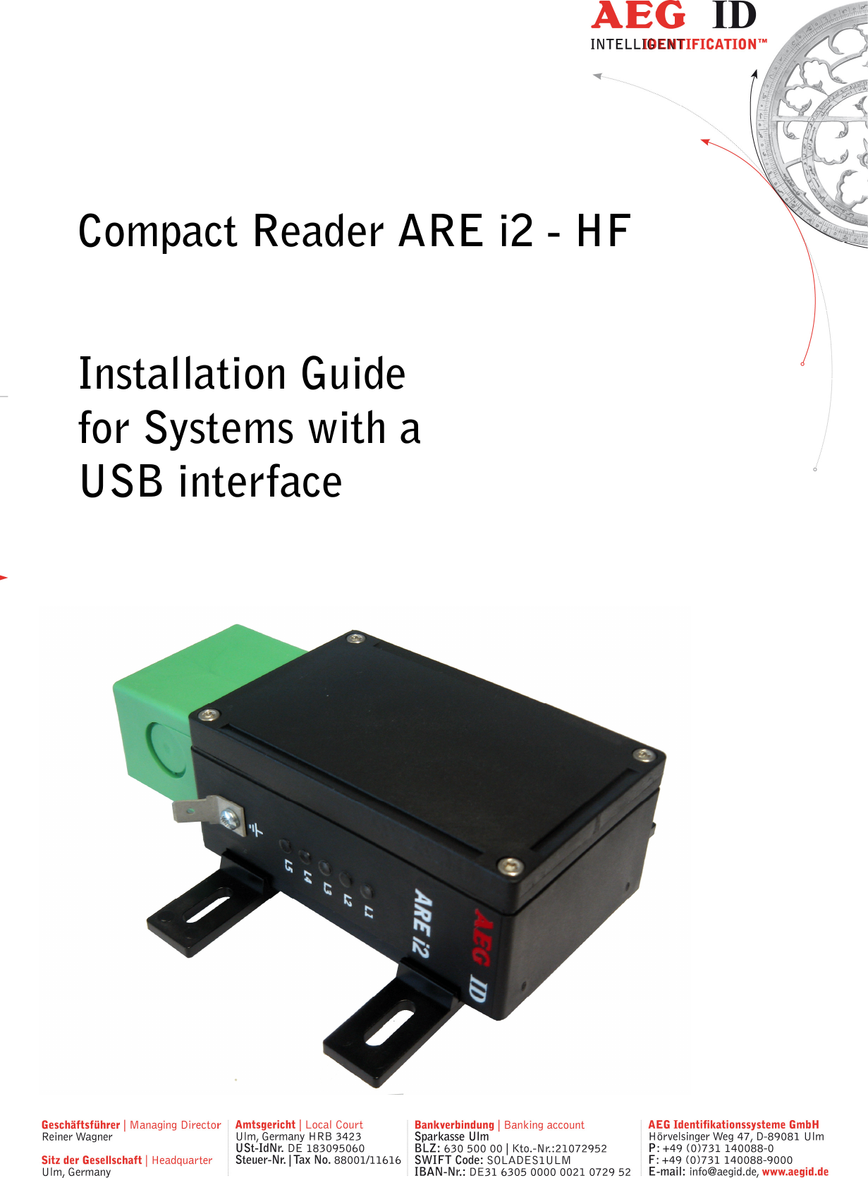
AEG Identifikationssysteme AREI2HF-1 RFID Reader User Manual Installation Guide ARE i2 HF USB 01

AEG Identifikationssysteme GmbH RFID Reader Installation Guide ARE i2 HF USB 01

user manual

        Compact Reader ARE i2 - HF  Installation Guide for Systems with a  USB interface
                 --------------------------------------------------------------------------------2/48--------------------------------------------------------------------------------      1 INTRODUCTION ............................................................................................................ 5 2 SYSTEM OVERVIEW .................................................................................................... 5 3 INSTALLATION ............................................................................................................. 5 3.1 Mounting of the housing ............................................................................................................................ 5 3.2 Grounding of the reader ............................................................................................................................ 6 3.2.1 Connecting of the plug ........................................................................................................................ 6 3.3 Connecting of the power supply cable ........................................................................................................ 7 3.3.1 Using the pc connection cable ID 1002237 ......................................................................................... 7 3.3.2 Using a self assembled connecting cable .............................................................................................. 8 3.3.2.1 Assembling of the cable pipe ........................................................................................................ 8 3.3.2.2 Mounting of the cable ................................................................................................................. 9 3.3.2.3 Pin assignment of the SAB connectors ....................................................................................... 10 3.4 Mounting of the external antenna / of the AMP 4 / AMP 8 ...................................................................... 11 4 VISUAL SIGNAL LAMPS ............................................................................................ 12 5 AEG ID INSTRUCTION SET ........................................................................................ 13 5.1 General ................................................................................................................................................... 13 5.1.1 Entering instuctions ......................................................................................................................... 13 5.1.2 Output format .................................................................................................................................. 14 5.1.2.1 Instruction specific output ......................................................................................................... 14 5.1.2.2 Output after changing a parameter ............................................................................................ 14 5.1.2.3 Output at parameter query ......................................................................................................... 14 5.1.3 Blank instuction ............................................................................................................................... 14 5.1.4 Incorrect instruction / error codes ..................................................................................................... 15 5.1.5 Upper and lower case ....................................................................................................................... 16 5.1.6 Linefeed ........................................................................................................................................... 16 5.2 Instructions for the hardware settings...................................................................................................... 17 5.2.1 BD – baudrate .................................................................................................................................. 17 5.2.2 RE – read EEPROM ........................................................................................................................ 17 5.2.3 RF – radio frequency ........................................................................................................................ 17 5.2.4 RST – reset ...................................................................................................................................... 18 5.2.5 WE – write EEPROM ...................................................................................................................... 19 5.2.6 VER – version .................................................................................................................................. 19 5.3 Instructions for reading settings .............................................................................................................. 20 5.3.1 CE – convert error code .................................................................................................................... 20 5.3.2 CID – suppression of ID Codes .......................................................................................................... 20
                 --------------------------------------------------------------------------------3/48--------------------------------------------------------------------------------  5.3.3 CN – suppression of No Reads .......................................................................................................... 21 5.3.4 INIT – initialization ......................................................................................................................... 22 5.3.5 MC – mirror code ............................................................................................................................. 22 5.3.6 TOR – maximum reading time .......................................................................................................... 22 5.3.7 SI – set iso standard ......................................................................................................................... 23 5.3.8 VSAVE – variables save ................................................................................................................... 23 5.3.9 VS – variables show ......................................................................................................................... 23 5.4 General reading instructions .................................................................................................................... 25 5.4.1 GA – get active ................................................................................................................................. 25 5.4.2 GT – get tag ..................................................................................................................................... 25 5.4.3 HD – halt detected code .................................................................................................................... 26 5.4.4 MD – mode of operation ................................................................................................................... 26 5.4.5 RD – read page ................................................................................................................................ 26 5.4.6 RDM – read page manual ................................................................................................................. 27 5.4.7 WD – write page .............................................................................................................................. 28 5.4.8 WDM – write page manual ............................................................................................................... 29 5.5 Mifare instructions .................................................................................................................................. 31 5.5.1 AC – anticollision ............................................................................................................................. 31 5.5.2 AC2 – anticollision ........................................................................................................................... 31 5.5.3 KM – key mode ................................................................................................................................ 31 5.5.4 KT – key type ................................................................................................................................... 31 5.5.5 LOG – transponder log in .................................................................................................................. 32 5.5.6 PBU – purse backup ......................................................................................................................... 32 5.5.7 PDC – purse decrement .................................................................................................................... 33 5.5.8 PIC – purse increment ...................................................................................................................... 34 5.5.9 PIV – purse init value ....................................................................................................................... 35 5.5.10 PRV – purse read value .................................................................................................................... 35 5.5.11 RQ – request .................................................................................................................................... 36 5.5.12 SE – select ....................................................................................................................................... 36 5.5.13 SE2 – select level 2 .......................................................................................................................... 36 5.5.14 WK – write key ................................................................................................................................ 37 5.6 ISO 15693 instructions............................................................................................................................ 38 5.6.1 AFI – application family identifier .................................................................................................... 38 5.6.2 BS – block size ................................................................................................................................. 38 5.6.3 GMS – get multiple block security .................................................................................................... 38 5.6.4 GS – get system information ............................................................................................................. 39 5.6.5 LA – lock AFI .................................................................................................................................. 39 5.6.6 LD – lock data ................................................................................................................................. 39 5.6.7 LDS – lock DSFID ........................................................................................................................... 40 5.6.8 RTR – reset to ready ........................................................................................................................ 40 5.6.9 WA – write AFI ............................................................................................................................... 40 5.6.10 WDS – write DSFID ......................................................................................................................... 40 6 OPERATING MODES OF THE READER ...................................................................... 42 6.1 MD 2 - Triggered by an Software Command ............................................................................................ 42 6.2 MD 0 - Continuous Reading ..................................................................................................................... 43 7 STARTUP AND TESTING THE READER .................................................................... 44
                 --------------------------------------------------------------------------------4/48--------------------------------------------------------------------------------  8 INSTRUCTIONS .......................................................................................................... 45 9 FCC INFORMATION .................................................................................................... 46 10 HOTLINE .................................................................................................................. 47 11 REVISIONS .............................................................................................................. 48
                 --------------------------------------------------------------------------------5/48--------------------------------------------------------------------------------  1 Introduction This document will describe the components of the Compact Reader System ARE i2 / RS 232 and the procedure how to do the first set up of the reader. The main features of the reader are listed below: • integrated USB Interface with tunable baudrate • the allowed supply voltage is 9 to 30V DC • low power consumption of reader < 1.2 Watt • high reliability for reading and writing within an industrial environment • compact housing of the reader with multiple ways for mounting • the cabling concept of the reader is optimised to service demands • the protection class of the housing is IP65 • there is a set of external antennas available to meet special application demands (X-tended version)  2 System overview The ARE i2 HF is only available with external antenna. 3 Installation To get the specified reading performance it is necessary to do the installation carefully step by step as it is described in the following Chapters. All the work must be done by well educated people. 3.1 Mounting of the housing The reader can be mounted to any other mechanic construction. The distance between reader and tran-sponder has to tuned
                 --------------------------------------------------------------------------------6/48--------------------------------------------------------------------------------  It is recommended to protect the housing against heavy mechanical interactions and drippy fluids.  Attention! The side of the housing showing the antenna symbol must not be brought next to a metal surface. This could lead to a significant change of the properties of the antenna circuit, which in turn reduces the reading range considerably. With the help of the plastic bars, the reader can mounted or screwed on to the most fastening elements without open the housing of the device.  3.2 Grounding of the reader To get reliable reading results, the reader must be grounded. The connector is placed at the side of the housing (6.35 mm flat contact). To avoid EMV-problems, the cable to ground ought to be very short with low impedance.  Attention! The topology of the ground wires must be done in the right way (according state of art). 3.2.1 Connecting of the plug  Attention! Be sure that the grounding of the reader is well done and the power supply is not connected(chapter 3.2). Otherwise the electronic may be destroyed by electrostatic discharge (ESD).
                 --------------------------------------------------------------------------------7/48--------------------------------------------------------------------------------   Figure 1: Connecting of the plug Put on the sealing 2 to the SAB Cab (A). Plug in the SAB Cab to the connector at the bottom of the reader device (B). There is only one way to plug in the SAB Cab to the connector rim of the reader. Fasten the SAB Cab with the help of the screws. To meet the protection class of IP 65, it’s necessary to apply a turning moment of 0.5 Nm to the screws.  3.3 Connecting of the power supply cable The reader has to be supplied with 9..30V DC. The maximum output power of the power supply has to be 1.2 Watt. Be sure that you use the right polarity. 3.3.1 Using the pc connection cable ID 1002237 Power supply:    brown =  + 9 .. 30 Volt       white =   ground 12AB
                 --------------------------------------------------------------------------------8/48--------------------------------------------------------------------------------  3.3.2 Using a self assembled connecting cable Using the following SAB cabs you can assemble your own connecting cable. ID 70211  SAB cab with 1 PG9 cable pipe ID 70215  SAB cab with 2 pre-assembled cable pipes ID 70219  SAB cab without any cable pipe ID 1002237  pc connection cable for ARE i2- USB  ID 1002373  pc connection cable for ARE i2- USB with  power supply 12V  You can use any shielded five-pole cable. The allowed diameter of the cable must be in the range from  ∅3,5 to ∅8mm. For this case, IP 65 is reached. Attention! The minimum voltage at the readers input mustn’t be lower then 9V. The maximum length of the serial USB cable is 5m. 3.3.2.1 Assembling of the cable pipe • Breakthrough the prepared areas at the surface of the SAB Cabs. There are two prepared areas seen at the SAB Cab: central and at one side of the cab. • The o-ring (3) has to be assembled proberly to the cable pipe (4) to ensure the protection class IP 65.  1234 Figure 2: Assembling of the cable pipe • Bring the nut (2) of the cable pipe inside of the SAB Cab (1). • To fasten the nut please use the right tool (17mm).
                 --------------------------------------------------------------------------------9/48--------------------------------------------------------------------------------  34516Cable73.3.2.2 Mounting of the cable The cable must be mounted in following steps: • Remove all inner parts from the cable pipe at the SAB Cab (1) ( nut (5), cable fastener (3), pipe(4)) (see Figure 3) • Put all the removed parts (nut (5), cable fastener (3), pipe (4),) and the cable pipe of the SAB Cab as well (1 to 4) to the cable.        Figure 3: Mounting for the cable • Remove the outer isolation of the cable at a length of 6cm . • Remove the isolation of the wires at a length of 6mm and stick a covering hull to the litz wire. • Put the cable to the cable pipe. The length of the cable coming out the SAB Cab must long enough to do all further installation steps in an easy way. • Stick the pipe (4) into the cable fastener (3). • Stick the cable fastener (3) into the cable pipe. • Connect the cables into the right places of the MINI-COMBICON-Connectors (6).  • The pin assignment is shown in the figure below. • Put the MINI-COMBICON-Connectors into the SAB cab. Look after the color coding.
                 --------------------------------------------------------------------------------10/48--------------------------------------------------------------------------------  3.3.2.3 Pin assignment of the SAB connectors          Figure 4: Pin assignment of the SAB connectors           Figure 5: Pin assignment of the SAB connectors USB ConnectorTyp: USB AD+ - greenGND - blackblackgreenID1002237V+DCV+DC - brownD-  - white+US2-US2+US1-US1BADECGND - white3 mVBus - redPowerUSB ConnectorType: USB AD+ - greenGND -blackbluegreyID1002237V+DCV+DC - brownD-  - whiteLUL+US-USGFJKHGND - white3 mVBus - redPower
                 --------------------------------------------------------------------------------11/48--------------------------------------------------------------------------------  3.4 Mounting of the external antenna / of the AMP 4 / AMP 8 If you have an i2 with external antenna the connector is on the topside of the reading device. You just have to plug the antenna into the connector and bold it on. Alternative you can connect an AMP 4 / AMP 8 with this connector, too. You may not connect or deconnect an antenna or AMP 4 / AMP 8 while the reader is running. It can cause, that the reader hangs up.
                 --------------------------------------------------------------------------------12/48--------------------------------------------------------------------------------  BFH IDL1L2L4L3L5ARE i24 Visual signal lamps To show the operational state or results there are 5 LED at the side of the housing.   L1: twinkles, if the processor works. L2: twinkles one time after successful instruction L3: twinkles one time after bad instruction L4: lit, if the reader receives data’s at the serial data port (Rx) L5: lit, if the reader sends data’s at the serial data port (Tx)     Figure 6: Visual signal lamps
                 --------------------------------------------------------------------------------13/48--------------------------------------------------------------------------------  5 AEG ID instruction set 5.1 General The command set described below defines the transfer of data on the serial interface. The commands consist of a command code and optionally of a parameter value. Commands are ter-minated by the control character <CR> (0Dh). The control character serves as command line termi-nator. Command codes and parameters,including all letters and numerical values, are principally transmit-ted as a sequence of ASCII characters (the value 255 (decimal) consequently as 32H, 35H, 35H; the command RST as 52H, 53H, 54H). All numbers (e.g. sectors, blocks) are in the hexadecimal format (see chapter 9). With the command CS you can change to the alternative instruction set. If the reader is set to alter-native instruction set, you can change back to the AEG ID instruction set via the command AEG (see chapter 5.3.3).  5.1.1 Entering instuctions The protocol format is as follows Command <SP> parameter <CR>  The space character <SP> separates commands from parameters and the <CR> character acts as command line terminator. For commands without parameter values (e.g. GT ) the <SP> character and parameter values are omitted. The command line is as short as this: Command <CR>
                 --------------------------------------------------------------------------------14/48--------------------------------------------------------------------------------  5.1.2 Output format Generally, every input terminated by <CR> is acknowledged by the reader. The following response protocols are different: 5.1.2.1 Instruction specific output After entering a valid command without a parameter value, the system answers by sending the param-eter value and <CR>. Example: Command:  GT <CR> Output: Transponder number or No Read <CR> 5.1.2.2 Output after changing a parameter After entering a valid command together with a parameter value, the system answers by sending the parameter value and <CR>. Example: Command:  MD <SP> 2 <CR> Output:   2 <CR>  After entering an invalid parameter value, the system answers with the corresponding error code. Error message: Command:  MD <SP> 4 <CR> Output:  NAK <SP> #02 <CR>  5.1.2.3 Output at parameter query Parameter settings can be queried by sending the command without adding a parameter value. Exam-ple:  Command:  MD <CR> Output:   2 <CR>  5.1.3 Blank instuction If a single <CR> is input, the reader answers with a single <CR>. Example:
                 --------------------------------------------------------------------------------15/48--------------------------------------------------------------------------------   Command:  <CR> Output:   <CR>  5.1.4 Incorrect instruction / error codes If a command is not entered correctly, the reader sends one of the following error codes: ERROR CODE  MEANING NAK #00 <CR>  unknown command NAK #02 <CR>  wrong parameter NAK #03 <CR>  EEPROM error NAK #04 <CR>  wrong transponder type/command not available NAK #05 <CR>  buffer overflow NAK #06 <CR>  not logged in NAK #08 <CR>  wrong password NAK #10 <CR>  antenna failure NAK #11 <CR>  anticollision error level 1 NAK #12 <CR>  anticollision error level 2 NAK #13 <CR>  select error level 1 NAK #14 <CR>  select error level 2 NAK #15 <CR>  transceiver IC error NAK #16 <CR>  not acknowlegde NAK #17 <CR>  no valid value block NAK #18 <CR>  EEPROM full NAK #19 <CR>  code already saved in EEPROM NAK #20 <CR>  Decoder communication error NAK #21 <CR>  wrong standard NAK #22 <CR>  wrong transpondercode length NAK #23 <CR>  transpondercode length and transponder don’t match NAK #24 <CR>  data is not multiple of the block size NAK #25 <CR>  data length shorter than block size NAK #26 <CR>  no communication to AMP NAK #40 <CR>  ISO 15693 error 01h: command not supported
                 --------------------------------------------------------------------------------16/48--------------------------------------------------------------------------------  NAK #41 <CR>  ISO 15693 error 02h: command not recognized NAK #42 <CR>  ISO 15693 error 03h: option not supported NAK #43 <CR>  ISO 15693 error 0Fh: unknown error (default) NAK #44 <CR>  ISO 15693 error 10h: block does not exist NAK #45 <CR>  ISO 15693 error 11h: block already locked NAK #46 <CR>  ISO 15693 error 12h: block cannot be changed (locked) NAK #47 <CR>  ISO 15693 error 13h: not successfully programmed NAK #48 <CR>  ISO 15693 error 14h: not successfully locked NAK #49 <CR>  ISO 15693 error A0h-DFh: custom error codes NAK #50 <CR>  all other ISO 15693 errors: RFU XXXXXXXX <CR>  no read ACK  no error/acknowledge  5.1.5 Upper and lower case The instruction set isn’t case-sensitiv. 5.1.6 Linefeed The reader does never send a linefeed. If you use a terminal program it can add the linefeed. You have to choose the option “displace CR with CR LF”.
                 --------------------------------------------------------------------------------17/48--------------------------------------------------------------------------------  5.2 Instructions for the hardware settings 5.2.1 BD – baudrate The command BD enables the change of the baud rate. The settings are directly effective. Input format:  BD <SP> parameter <CR> Output (example):  2 <CR> Parameter:  PARAMETER  FUNCTION 0  4800 baud 1  9600 baud 2  19200 baud 3  38400 baud 4  57600 baud 5  115200 baud 5.2.2 RE – read EEPROM You can read out the internal EEPROM with the RE command. Input format:  RE <SP> parameter <CR> Output (example):  FF <CR> Parameter: PARAMETER  FUNCTION 0000h..079Fh  address  5.2.3 RF – radio frequency With the command RF you can switch the antenna field on and off. Input format:  RF <SP> parameter <CR>
                 --------------------------------------------------------------------------------18/48--------------------------------------------------------------------------------  Output (example):  1 <CR> Parameter: PARAMETER  FUNCTION 0  off 1  on  5.2.4 RST – reset With the command RST the reader does a warmstart and loads the saved settings from the internal EEPROM. The antenna field is off after the reset. Input format:  RST <CR> Output (example):  ACK <CR>
                 --------------------------------------------------------------------------------19/48--------------------------------------------------------------------------------  5.2.5 WE – write EEPROM Using the command WE you can write one byte to the internal EEPROM. Input format:  WE <SP> parameter 1 <SP> parameter 2 <CR> Output (example):  FF <CR> Parameter: PARAMETER 1  FUNCTION 0005h..079Fh  address  PARAMETER 2  FUNCTION 00h..FFh  data  5.2.6 VER – version With the command VER the reader sends the actual firmware version. Input format:  VER <CR> Output (example):  AEG ID V1.22 <CR>
                 --------------------------------------------------------------------------------20/48--------------------------------------------------------------------------------  5.3 Instructions for reading settings 5.3.1 CE – convert error code With CE=1 the reader sends no error  codes, except the  no read  error, during the  md0 mode or the commands Get Tag. The leds are not influenced by this command. This command has only effect in the ISO 14443A standard. This  command  is  not  available  in  profibus  communication  and  can  not  be  saved  with  the  VSAVE command. Input format:  CE <SP> parameter <CR> Output (example):  0 <CR> Parameter: PARAMETER  FUNCTION 0  No suppression 1  Suppression of error codes  5.3.2 CID – suppression of ID Codes In the MD0 mode with CID=1 only the first of in succession identical transponder numbers is output on the serial interface. The possibly following identical transponder numbers are suppressed, as long as no new valid transponder number is received, processed and output. The get tag command is not influenced by this command. NoReads do not influence the data filtering. This  command  is  not  available  in  profibus  communication  and  can  not  be  saved  with  the  VSAVE command. Input format:  CID <SP> parameter <CR> Output (example):  0 <CR> Parameter: PARAMETER  FUNCTION 0  No suppression 1  Suppression of equal transponder numbers
                 --------------------------------------------------------------------------------21/48--------------------------------------------------------------------------------  Example: A, B, C are different transponder codes, N is NoRead error code:    Sequence of reading cycles  Output sequence after filtering with CN=0 und CID=1 Output sequence after filtering with CN=1 und CID=1 N, N, ......,N, A, A, A, ....A, N,N, ......... N, N, ......,N, A, N, N, ....... A N. N, N, A, A, A, N, A, A, B, A, C, C, C, ....... N. N, N, A, N, B, A, C, ..... A, B, A, C  The settings are directly effective. Note:  The internal reference number is deleted in the following conditions:  • after a cold start • after a warm start (command line RST <CR>) • after entering the command line CID <SP> 1 <CR> This causes that the next transponder code is output definitely. Note: The filter function CID picks up the results of the complete reading cycles, while the parameter NID proceeds from the results of single readings! The filter function CID has effect on the serial in-terface only.  5.3.3 CN – suppression of No Reads Through  the  setting  CN=1  the  NoRead  results  after  a  get  tag  command  or in  MD0  mode are  sup-pressed on the serial interface. This  command  is  not  available  in  profibus  communication  and  can  not  be  saved  with  the  VSAVE command. Input format:  CN <SP> parameter <CR> Output (example):  0 <CR> Parameter:
                 --------------------------------------------------------------------------------22/48--------------------------------------------------------------------------------  PARAMETER  FUNCTION 0  No suppression 1  Suppression of equal transponder numbers 5.3.4 INIT – initialization With the command INIT all paramters of this command set are set to the default values. After that you can save the settings with the command VSAVE.  Input format:  INIT <CR> Output (example):  ACK <CR> 5.3.5 MC – mirror code With this command you can change the output order of the bytes from a transpondercode.  Input format:  MC <CR> Output (example):  0 <CR> 5.3.6 TOR – maximum reading time Timeout time for the reader. TOR is used in operation mode 2 as maximum gating time for a reading process. The length of the maximum gating time results from the equation gating_time = TOR * TB. The time constant TB (time base) has always the default value 100ms.  Input format:  TOR <SP> parameter <CR> Output (example):  05 <CR> Parameter: PARAMETER  FUNCTION 00h  limits the reading process duration of exactly one reading cycle 01h..FFh  limits the reading process duration to maximum 1..256 times TB
                 --------------------------------------------------------------------------------23/48--------------------------------------------------------------------------------  5.3.7 SI – set iso standard With this command you can switch the iso standard of the reader.  Input format:  SI <SP> parameter <CR> Output (example):  0 <CR> Parameter: PARAMETER  FUNCTION 0  ISO 14443A 1  ISO 15693 5.3.8 VSAVE – variables save With the command VSAVE the following parameters are saved to the internal EEPROM: AFI2, KM1, KT1, MD, SI, TOR  Input format:  VSAVE <CR> Output (example):  ACK <CR> 1 just available in the ISO 14443A standard 2 just available in the ISO 15693 standard 5.3.9 VS – variables show With the command VS the reader shows the settings of the following parameters: AFI2, KM1, KT1, MD, SI, TOR  Input format:  VS <CR> Output (example):  ACT <SP> 14 <CR>  AM <SP> 0 <SP>   …
                 --------------------------------------------------------------------------------24/48--------------------------------------------------------------------------------  Note: The function VS shows just the settings that are used in the actual ISO standard. 1 just available in the ISO 14443A standard 2 just available in the ISO 15693 standard
                 --------------------------------------------------------------------------------25/48--------------------------------------------------------------------------------  5.4 General reading instructions 5.4.1 GA – get active The command GA causes one reading cycle. There are different cycles for different transpondertypes. This command is only available in the ISO 14443A standard. Mifare standard 1K/4K:  request (REQA)         anticollision         select Mifare Ultralight/Desfire  request (REQA)         anticollision level 1         select 1         anticollision level 2         select 2 The reader answers the UID of an active (non halt) transponder. The length of the UID can be be-tween 4 and 7 bytes. Input format:    GA <CR> Output (example):  625E562A <CR> 5.4.2 GT – get tag With the command GT you select a transponder. The command GT causes one reading cycle. There are different cycles for different transpondertypes. Mifare standard 1K/4K:  request (WUPA)         anticollision         select Mifare Ultralight/Desfire:  request (WUPA)         anticollision level 1         select 1
                 --------------------------------------------------------------------------------26/48--------------------------------------------------------------------------------          anticollision level 2         select 2 ISO 15693:      inventory The reader answers the UID of a transponder. The length of the UID can be between 4 and 8 bytes. Input format:    GT <CR> Output (example):  625E562A <CR> 5.4.3 HD – halt detected code The command HD mutes the last selected transponder. Input format:    HD <CR> Output (example):  ACK <CR> 5.4.4 MD – mode of operation There a two modes of operation available. It is possible, that the reader reads constantly or triggered by an instruction. Input format:    MD <SP> parameter <CR> Output (example):  2 <CR> Parameter: PARAMETER  FUNCTION 0  constant reading mode 2  single reading mode  5.4.5 RD – read page With the command RD you can read out a page of the transponder. The command executes internally the commands get tag, if using mifare 1K/4K log in (with the key attuned to KM) and the reading command. Input format mifare 1K/4K:      RD <SP> parameter 1 <SP> parameter 2 <CR> Input format ultralight:      RD <SP> parameter 2 <CR>
                 --------------------------------------------------------------------------------27/48--------------------------------------------------------------------------------  Input format ISO 15693 one block:    RD <SP> parameter 2 <CR> Input format ISO 15693 multiple blocks:  RD <SP> parameter 2 <SP> parameter 3 <CR> Output:           parameter 4 <CR> Parameters: PARAMETER 1  FUNCTION 1 or 2 characters  sector PARAMETER 2  FUNCTION 1 or 2 characters  block/start block  PARAMETER 3  FUNCTION 1 or 2 characters  end block  PARAMETER 4  FUNCTION 32 characters  data (mifare 1K/4K) 8 characters  data (ultralight) up to 64 charac-ters data (ISO 15693)  5.4.6 RDM – read page manual With the command RDM you can read out a page of the transponder. The reading command is executed single. You have to do a get tag first. If you are using a mifare standard 1K/4K you have to log in, too. Input format mifare 1K/4K:      RD <SP> parameter 1 <SP> parameter 2 <CR> Input format ultralight:      RD <SP> parameter 2 <CR> Input format ISO 15693:      RD <SP> parameter 2 <CR> Input format ISO 15693 multiple blocks:  RD <SP> parameter 2 <SP> parameter 3 <CR> Output:           parameter 4 <CR>
                 --------------------------------------------------------------------------------28/48--------------------------------------------------------------------------------  Parameters: PARAMETER 1  FUNCTION 1 or 2 characters  sector  PARAMETER 2  FUNCTION 1 or 2 characters  block/start block   PARAMETER 3  FUNCTION 1 or 2 characters  end block  PARAMETER 4  FUNCTION 32 characters  data (mifare 1K/4K) 8 characters  data (ultralight) up to 64 charac-ters data (ISO 15693)  5.4.7 WD – write page With the command WD you write one page to the transponder. The command executes internally the commands get tag, log in (with the key attuned to KM) and the writing command.  Input format mifare 1K/4K:  WD <SP> parameter 1 <SP> parameter 2 <SP> parameter 3 <CR> Input format ultralight:    WD <SP> parameter 2 <SP> parameter 3 <CR> Input format ISO 15693:    WD <SP> parameter 2 <SP> parameter 3 <CR> Output (example):      ACK <CR> Parameters: PARAMETER 1  FUNCTION 1 or 2 characters  sector
                 --------------------------------------------------------------------------------29/48--------------------------------------------------------------------------------   PARAMETER 2  FUNCTION 1 or 2 character  block  PARAMETER 3  FUNCTION 32 characters  mifare 1K/4K 8 characters  ultralight up to 32 charac-ters ISO 15693  Note: The ISO 15693 regulates just the maximum length of one block. With the write instruction you can write multiple blocks at once. The datalenght has to be at least the block size or a multiple of the block size.  5.4.8 WDM – write page manual With the command WDM you write one page to the transponder. The writing command is executed alone. You have to select the transponder first. If you are using a mifare standard 1K/4K you have to log in, too.  Input format mifare 1K/4K:  WD <SP> parameter 1 <SP> parameter 2 <SP> parameter 3 <CR> Input format ultralight:    WD <SP> parameter 2 <SP> parameter 3 <CR> Output (example):      ACK <CR> Parameters: PARAMETER 1  FUNCTION 1 or 2 characters  sector  PARAMETER 2  FUNCTION 1 or 2 characters  block
                 --------------------------------------------------------------------------------30/48--------------------------------------------------------------------------------   PARAMETER 3  FUNCTION 32 characters  mifare 1K/4K 8 characters  ultralight up to 32 charac-ters ISO 15693  Note: The ISO 15693 regulates just the maximum length of one block. With the write instruction you can write multiple blocks at once. The datalenght has to be at least the block size or a multiple of the block size.
                 --------------------------------------------------------------------------------31/48--------------------------------------------------------------------------------  5.5 Mifare instructions 5.5.1 AC – anticollision The command AC answers with the UID of the transponder, that will be selected with the next select command. For ultralight and DESFire transponders it is the anticollision level 1 command. Input format:    AC <CR> Output (example):  595B1B80 <CR> 5.5.2 AC2 – anticollision With the command AC2 the reader executes the anticollision level 2 command. Input format:    AC2 <CR> Output (example):  595B1B80 <CR> 5.5.3 KM – key mode With the command KM you switch the key that is used by the commands RD and WD. It is possible to use the default key or one of the keys saved with the command WK. Input format:    KM <SP> parameter <CR> Output (example):  parameter <CR> PARAMETER  FUNCTION 0  use default key (FFFFFFFFFFFF) 1..8  use saved key 1 to 8  5.5.4 KT – key type With this command you switch if the key that is used with the commands RD and WD is type A or B. Input format:    KT <SP> parameter <CR> Output (example):  parameter <CR>
                 --------------------------------------------------------------------------------32/48--------------------------------------------------------------------------------  PARAMETER  FUNCTION A  key type A B  key type B  5.5.5 LOG – transponder log in The command LOG is only valid with mifare standard 1K/4K transponders. The log in is necessary to read or write a page: Input format:    LOG <SP> parameter 1 <SP> parameter 2 <SP> parameter 3 <CR> Input (example):  LOG <SP> A <SP> 1 <SP> FFFFFFFFFFFF <CR> Output (example):  ACK <CR> Parameters: PARAMETER 1  FUNCTION A or B  type of the key  PARAMETER 2  FUNCTION 1 or 2 characters  sector  PARAMETER 3  FUNCTION 12 characters  key  5.5.6 PBU – purse backup With this command it is possible to copy a purse value to an other block of the same sector. This com-mand is only valid with mifare standard 1K/4K. You have to log in first. Input format:    PBU <SP> parameter 1 <SP> parameter 2 <SP> parameter 3 <CR> Output:     parameter 4 <SP> parameter 5 <CR> Parameters: PARAMETER 1  FUNCTION 1 or 2 characters  sector
                 --------------------------------------------------------------------------------33/48--------------------------------------------------------------------------------  PARAMETER 2  FUNCTION 1 character  source block  PARAMETER 3  FUNCTION 1 character  target block  PARAMETER 4  FUNCTION 8 characters  new purse value  PARAMETER 5  FUNCTION 2 character  optional address  5.5.7 PDC – purse decrement With this command you can decrement a value. This command is only valid with mifare standard 1K/4K. You have to log in first. Input format:    PDC <SP> parameter 1 <SP> parameter 2 <SP> parameter 3 <CR> Output:     parameter 4 <SP> parameter 5 <CR> Parameters: PARAMETER 1  FUNCTION 1 or 2 characters  sector  PARAMETER 2  FUNCTION 1 character  block  PARAMETER 3  FUNCTION 8 characters  value change
                 --------------------------------------------------------------------------------34/48--------------------------------------------------------------------------------   PARAMETER 4  FUNCTION 8 characters  new purse value  PARAMETER 5  FUNCTION 2 character  optional address  5.5.8 PIC – purse increment With this command you can increment a value. This command is only valid with mifare standard 1K/4K. You have to log in first. Input format:    PDC <SP> parameter 1 <SP> parameter 2 <SP> parameter 3 <CR> Output:     parameter 4 <SP> parameter 5 <CR> Parameters: PARAMETER 1  FUNCTION 1 or 2 characters  sector  PARAMETER 2  FUNCTION 1 character  block  PARAMETER 3  FUNCTION 8 characters  value change  PARAMETER 4  FUNCTION 8 characters  new purse value  PARAMETER 5  FUNCTION 2 character  optional address
                 --------------------------------------------------------------------------------35/48--------------------------------------------------------------------------------  5.5.9 PIV – purse init value With this command you can initialize a value. This command is only valid with mifare standard 1K/4K. You have to log in first. Input format:  PIV <SP> parameter 1 <SP> parameter 2 <SP> parameter 3 <SP> param-eter 4 <CR> Output:     parameter 3 <SP> parameter 4 <CR> Parameters: PARAMETER 1  FUNCTION 1 or 2 characters  sector  PARAMETER 2  FUNCTION 1 character  block  PARAMETER 3  FUNCTION 8 characters  value  PARAMETER 4  FUNCTION 2 characters  optional address  5.5.10 PRV – purse read value With this command you can read out a value. This command is only valid with mifare standard 1K/4K. You have to log in first. Input format:  PRV <SP> parameter 1 <SP> parameter 2 <CR> Output:     parameter 3 <SP> parameter 4 <CR> Parameters: PARAMETER 1  FUNCTION 1 or 2 characters  sector
                 --------------------------------------------------------------------------------36/48--------------------------------------------------------------------------------  PARAMETER 2  FUNCTION 1 character  block  PARAMETER 3  FUNCTION 8 characters  value  PARAMETER 4  FUNCTION 2 characters  optional address  5.5.11 RQ – request The RQ command answers the type of the detected transponder. Input format:    RQ <SP> parameter <CR> Output (example):  ACK <CR> Parameters: PARAMETER  FUNCTION 0  non halt transponders 1  all transponders  5.5.12 SE – select The command SE selects that transponder that answered at the anticollision. For ultralight and DESFire transponders it is select level 1 command. Input format:    SE <CR> Output (example):  ACK <CR> 5.5.13 SE2 – select level 2 The command SE2 selects that transponder that answered at the anticollision level 2. For ultralight and DESFire transponders it is select level 2 command. Input format:    SE2 <CR>
                 --------------------------------------------------------------------------------37/48--------------------------------------------------------------------------------  Output (example):  ACK <CR> 5.5.14 WK – write key With the command WK you save a key to the EEPROM. You can save 8 different keys. It is not possible to read out the saved keys. Input:      WK <SP> parameter 1 <SP> parameter 2 <CR> Output (example):  ACK <CR> Parameters: PARAMETER 1  FUNCTION 1..8  key number  PARAMETER 2  FUNCTION 12 characters  6 byte key
                 --------------------------------------------------------------------------------38/48--------------------------------------------------------------------------------  5.6 ISO 15693 instructions 5.6.1 AFI – application family identifier With this command you can change the application family identifier of the reader. The reader reads only transponders, with the same application family identifier as the reader. If the application family identifi-er is set to 00h the reader reads each transponder. Input format:  AFI <SP> parameter <CR> Output (example):  00 <CR> Parameter: PARAMETER  FUNCTION 00  every transponder is read 01h..FFh  just transponders with the same application identifier are read  5.6.2 BS – block size With the command BS you can choose the block size of the used transponder. If the ISO 15693 tran-sponders support the “get system information” command, the parameter BS is not used. Only if there is no information of the block size of the transponder available, the parameter regulates the reading pro-cess. The block size is defined in the ISO 15693, e.g. parameter 00H means the blocksize is 1 byte.  Input format:  BS <SP> parameter <CR> Output (example):  00 <CR> PARAMETER  FUNCTION 00h..1Fh  1 byte..32bytes   5.6.3 GMS – get multiple block security This commands shows if one/multiple blocks of a transponder are locked or not. You have to do a get tag first.
                 --------------------------------------------------------------------------------39/48--------------------------------------------------------------------------------  Input format one block:      GMS <SP> parameter 1 <CR> Input format multiple blocks:    GMS <SP> parameter 1 <SP> parameter 2 <CR> Output (example):      parameter 3 <CR> Parameter: PARAMETER 1  FUNCTION 1 or 2 characters  block/start block number  PARAMETER 2  FUNCTION 1 or 2 characters  end block number  PARAMETER 3  FUNCTION 00h  block is not locked 01h  block is locked 5.6.4 GS – get system information This command sends the get system information to the transponder. The answer format is described in the ISO 15693 chapter 9.3.12. You have to do a get tag first. Input format:  GS <CR> Output (example):  0F7FAA9006000104E000201B0301 <CR> 5.6.5 LA – lock AFI This command locks the AFI of a transponder. You have to do a get tag first. Input format:  LA <CR> Output (example):  ACK <CR> 5.6.6 LD – lock data This command locks the data of a block. You have to do a get tag first. Input format:  LD <SP> parameter <CR>
                 --------------------------------------------------------------------------------40/48--------------------------------------------------------------------------------  Output (example):  ACK <CR> Parameter: PARAMETER  FUNCTION 0h..FFh  block number 5.6.7 LDS – lock DSFID This command locks the DSFID of a transponder. You have to do a get tag first. Input format:  LDS <CR> Output (example):  ACK <CR> 5.6.8 RTR – reset to ready With this command the transponder enteres the ready state. A muted transponder answers again after this command. Input format:  RTR <CR> Output (example):  ACK <CR> 5.6.9 WA – write AFI With this command the reader writes the AFI into the transponder. You have to do a get tag first. Input format:  WA <SP> parameter <CR> Output (example):  ACK <CR> Parameter: PARAMETER  FUNCTION 00h..FFh  AFI 5.6.10 WDS – write DSFID With this command the reader writes the DSFID into the transponder. You have to do a get tag first. Input format:  WDS <SP> parameter <CR> Output (example):  ACK <CR>
                 --------------------------------------------------------------------------------41/48--------------------------------------------------------------------------------  Parameter: PARAMETER  FUNCTION 00h..FFh  DSFID
                 --------------------------------------------------------------------------------42/48--------------------------------------------------------------------------------  6 Operating Modes of the Reader There are two operational modes defined: • MD 0 - continuous mode • MD 2 - the reading process is triggered by the serial interface In the next capters can you find a detailed functional description. The default mode is MD 0. 6.1 MD 2 - Triggered by an Software Command The master sends the command to read a transponder code. The reader answers with the code or an error code. If you use “read- and writable”-transponders you just get the transponder code using the command “Get Tag” (GT). You can execute specific commands “Read” (RD) and “Write” (WD) just in mode MD2. (capter 8) In operating mode 2, the exciter is always turned off. Triggered by the software command (GT; RD ; WD), the exciter is activated. After successful reading or writing of a transponder number the exciter is turned off automatically. Figure 7: Software triggered reading operation If the first reading cycle yields no result (NoRead), the on-time of the exciter is limited by the param-eter TOR (time out reader): Reading cycles are continuously started until either a transponder is read successfully or the time span corresponding to the value of the parameter TOR has expired. The read-er  will  not  interrupt  the  last  running  readout  cycle.  If  no  transponder  number  has  been  read,  a NoRead is output.  exciterprocessorinterfacereading cycle IDGT
                 --------------------------------------------------------------------------------43/48--------------------------------------------------------------------------------   Figure 8: Software triggered reading operation with TOR>0  Please note: The TOR parameter is only active, if the  GT-Command is applied. Within the time span defined by the value of TOR no NoRead will be output on the interface!   6.2 MD 0 - Continuous Reading When operating continuously the exciter is switched on permanently. The reading cycles are initiated periodically. After an accomplished reading cycle the reading information is evaluated. After that data (either tran-sponder number or NoRead code) is output to the serial interface   Figure 9: continuous operation exciterprocessorinterfaceTORGTreading processNoReadreading cycle  reading cycle  reading cycle exciterprocessorinterfacereading cycle ID ID IDreading cycle  reading cycle
                 --------------------------------------------------------------------------------44/48--------------------------------------------------------------------------------  7 Startup and testing the reader • Connect the reader via cable with the serial interface (COM) from your notebook or pc. • Connect the reader with your power supply (9..30V DC). Look after the polarity! • Switch the power supply on. The yellow LED OP of the reader starts to blink. • Start your terminal programme. You have to set the following settings: 8 data bits, 1 start bit und 1 stop bit, no parity check (often called 8N1), baud rate 19200 baud, no flow control(e.g. XOFF/XON). • Send the command „VER <CR>“ to the reader. The reader answers with the actual firmware version (e.g. AEG ID V1.23). • Send the command “MD <SP> 0 <CR>” to the reader. The reader sends No Read messages (e.g. „FFFFFFFFFF“ or „XXXXXXXXXX“), while there is no transponder in the antenna field available. The red LED L3 is active. If there is a transponder in the antenna field available the reader sends its transponder code. The green LED L2 starts to glow.
                 --------------------------------------------------------------------------------45/48--------------------------------------------------------------------------------  8 Instructions  To avoid any reduction of the reading distance of the reader, the antenna must not be brought next to a metal surface. This could lead to a significant change of the properties of the antenna circuit, which in turn reduces the reading range considerably!  To get reliable readings, the distance between antenna and transponder must be within the specified reading volume.  The reading characteristic in front of the antenna is not isotropic. It depends also strongly on the orien-tation between antenna and transponder. To get the maximum reading distance, the orientation between reader and transponder must be well suited. The best orientation depends on the type of antenna inside of the housing ( ferrite – type or plane coil type) and the applied transponder. To get a reliable readings or writings, the time of transponder while crossing the sensitive area of the antenna must be coordinated to the data transfer characteristics of transponder  In general the time depends on the speed of the transponder, the size of the transponder and the way the transponder is mounted on the vehicle and must be verified by field tests. Environmental electromagnetic noise may also reduce the read and write range consid-erably.  Arrangement to eliminate such troubles must be done specific to the application by the help of engineers of the manufacturer.
                 --------------------------------------------------------------------------------46/48--------------------------------------------------------------------------------  9 FCC Information Federal Communications Commissions (FCC) Statement 15.21 You are cautioned that changes or modifications not expressly approved by the part responsible for com-pliance could void the user’s authority to operate the equipment. 15.105(b) This equipment has been tested and found to comply with the limits for a Class B digital device, pursuant to part 15 of the FCC rules. These limits are designed to provide reasonable protection against harmful interference in a residential installation. This equipment generates, uses and can radiate radio frequency energy and, if not installed and used in accordance with the instructions, may cause harmful interference to radio communications. However, there is no guarantee that interference will not occur in a particular installation. If this equipment does cause harmful interference to radio or television reception, which can be determined by turning the equipment off and on, the user is encouraged to try to correct the interfer-ence by one or more of the following measures: - Reorient or relocate the receiving antenna. - Increase the separation between the equipment and receiver. - Connect the equipment into an outlet on a circuit different from that to which the receiver is connect-ed. - Consult the dealer or an experienced radio/TV technician for help.
                 --------------------------------------------------------------------------------47/48--------------------------------------------------------------------------------   10 Hotline If there are questions or suggestions please call the hotline:  Sales und Marketing:     +49 (0)731-140088-0 Fax:        +49 (0)731-140088-9000 e-mail:       sales@aegid.de http://        www.aegid.de
                 --------------------------------------------------------------------------------48/48--------------------------------------------------------------------------------   11 Revisions 19.05.16  Revision 00:  Initial edition (FW) 22.06.16  Revision 01:  FCC information correction

Navigation menu