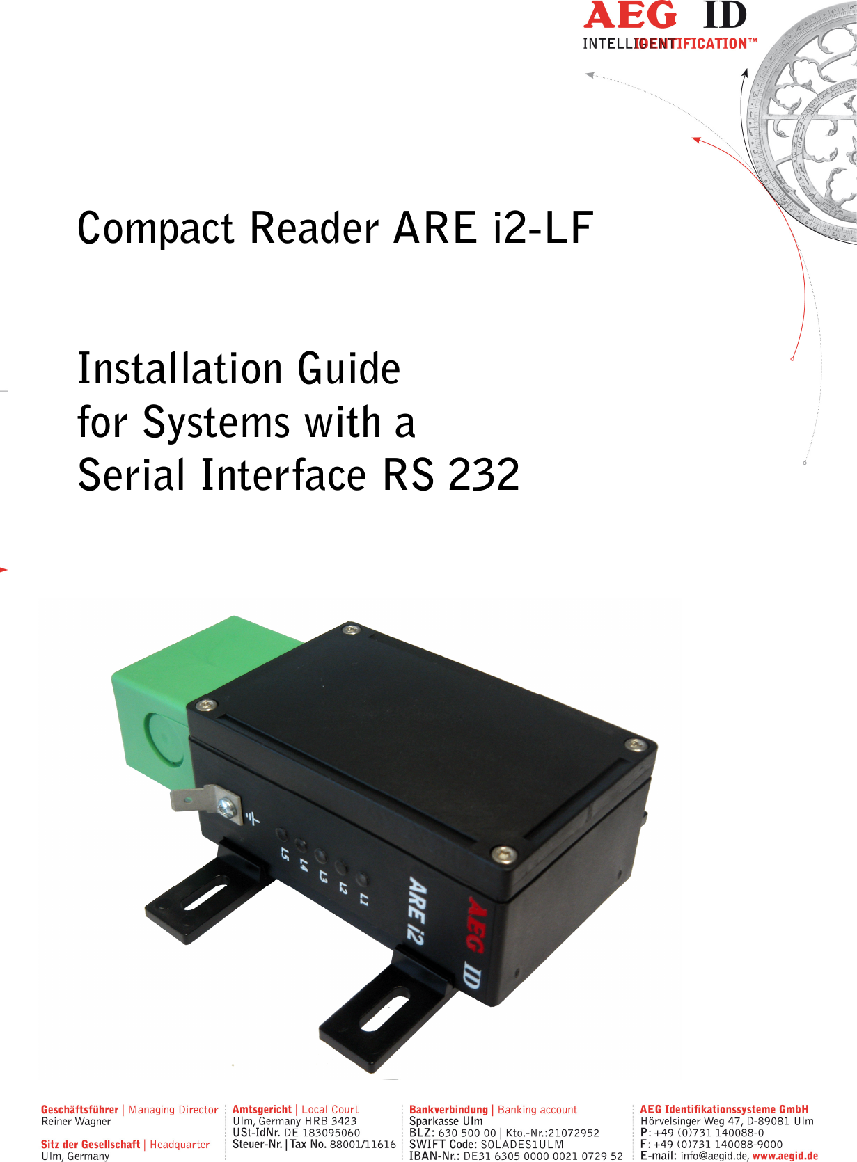
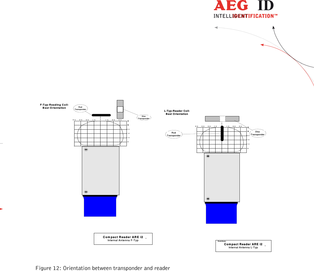
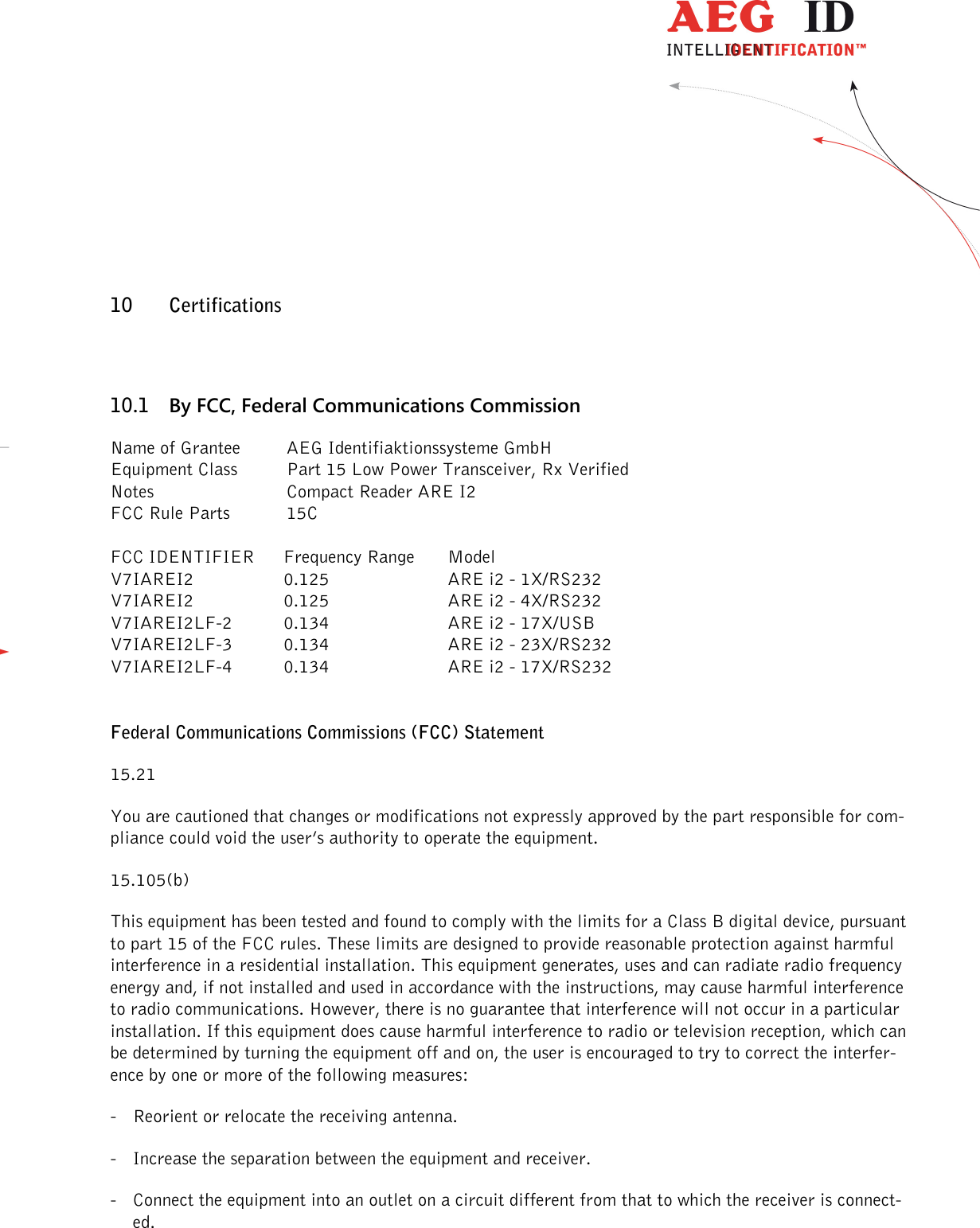
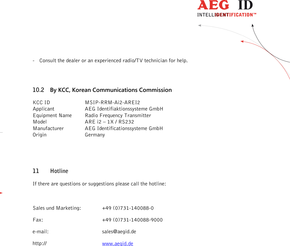
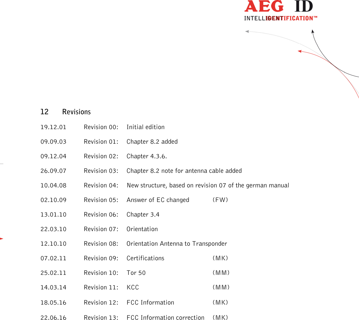
AEG Identifikationssysteme AREI2LF-4 Industrial LF-RFID Reader User Manual Installation Guide ARE i2 LF RS 232 13

AEG Identifikationssysteme GmbH Industrial LF-RFID Reader Installation Guide ARE i2 LF RS 232 13

User Manual

        Compact Reader ARE i2-LF  Installation Guide for Systems with a  Serial Interface RS 232
                 --------------------------------------------------------------------------------2/32--------------------------------------------------------------------------------      1 INTRODUCTION ............................................................................................................ 4 2 SYSTEM OVERVIEW .................................................................................................... 4 3 INSTALLATION ............................................................................................................. 5 3.1 Mounting of the housing ............................................................................................................................ 5 3.2 Grounding of the reader ............................................................................................................................ 5 3.2.1 Connecting of the plug ........................................................................................................................ 6 3.3 Connecting of the power supply cable ........................................................................................................ 7 3.3.1 Using the pc connection cable ID 70213 ............................................................................................. 7 3.3.2 Using the switchboard cable ID 70212 ................................................................................................ 7 3.3.3 Using a self assembled connecting cable .............................................................................................. 7 3.3.3.1 Assembling of the cable pipe ........................................................................................................ 8 3.3.3.2 Mounting of the cable ................................................................................................................. 8 3.3.3.3 Pin assignment of the SAB connectors ....................................................................................... 10 3.4 Mounting of the external antenna / of the AMP 4 / AMP 8 ...................................................................... 11 4 VISUAL SIGNAL LAMPS ............................................................................................ 12 5 INSTRUCTION SET / STRUCTURE OF THE INSTRUCTION SET ............................... 13 5.1 General ................................................................................................................................................... 13 5.1.1 Entering instuctions ......................................................................................................................... 13 5.1.2 Output format .................................................................................................................................. 13 5.1.2.1 Instruction specific output ......................................................................................................... 14 5.1.2.2 Output after changing a parameter ............................................................................................ 14 5.1.2.3 Output at parameter query ......................................................................................................... 14 5.1.3 Blank instuction ............................................................................................................................... 15 5.1.4 Incorrect instruction / error codes ..................................................................................................... 15 5.1.5 Upper and lower case ....................................................................................................................... 15 5.1.6 Linefeed ........................................................................................................................................... 15 5.2 Instructions for the hardware settings...................................................................................................... 16 5.2.1 BD - baudrate .................................................................................................................................. 16 5.2.2 EC – echo function ........................................................................................................................... 16 5.3 Instructions for the reading settings......................................................................................................... 17 5.3.1 GT – single transponder code reading ............................................................................................... 17 5.3.2 CID – Suppression of ID Codes ......................................................................................................... 17 5.3.3 CN – Suppression of No Reads ......................................................................................................... 18 5.3.4 NID – Failure Protection .................................................................................................................. 19 5.3.5 TOR – Maximum reading time .......................................................................................................... 19
                 --------------------------------------------------------------------------------3/32--------------------------------------------------------------------------------  5.4 Instructions for the memory settings ........................................................................................................ 20 5.4.1 VER – Reader firmware ................................................................................................................... 20 5.4.2 VS – Show parameter ....................................................................................................................... 20 5.4.3 VSAVE – Save parameter ................................................................................................................ 21 5.4.4 RST – Warm start ............................................................................................................................ 21 5.4.5 INIT – Warmstart with default parameters ....................................................................................... 21 6 OPERATING MODES OF THE READER ...................................................................... 22 6.1 MD 2 - Triggered by an Software Command ............................................................................................ 22 6.2 MD 0 - Continuous Reading ..................................................................................................................... 23 7 STARTUP AND TESTING THE READER .................................................................... 24 8 BASIC DATA EXCHANGE PROCESS .......................................................................... 25 8.1 Selective read RD ................................................................................................................................... 25 8.2 Writing WD............................................................................................................................................. 26 9 INSTRUCTIONS .......................................................................................................... 27 9.1 General Instructions ................................................................................................................................ 27 9.2 Special Instructions for Using a Read / Write System .............................................................................. 28 10 CERTIFICATIONS .................................................................................................... 30 10.1 By FCC, Federal Communications Commission ..................................................................................... 30 10.2 By KCC, Korean Communications Commission ..................................................................................... 31 11 HOTLINE .................................................................................................................. 31 12 REVISIONS .............................................................................................................. 32
                 --------------------------------------------------------------------------------4/32--------------------------------------------------------------------------------  1 Introduction This document will describe the components of the Compact Reader System ARE i2 / RS 232 and the procedure how to do the first set up of the reader. The main features of the reader are listed below: • the antenna is placed inside of the housing • there are algorithm available to read nearly all 125 kHz-transponders on market • integrated RS232 Interface with tunable baud rate are up to 19200 Bit/s • the allowed supply voltage is 9 to 30V DC • low power consumption of reader < 1.2 Watt • high reliability for reading and writing within an industrial environment • compact housing of the reader with multiple ways for mounting • the cabling concept of the reader is optimised to service demands • the protection class of the housing is IP65 • there is a set of external antennas available to meet special application demands ( X-tended version)  2 System overview In the base version all electronic components of the reader are placed inside of a small plastic housing.  By means of the integrated antenna the reader generates an alternating magnetic field, which powers the transponder. Coded signals sent back from the transponder are received and decoded by the reader. The reader is fully controlled by a master with RS 232 data port, while using the integrated serial RS 232 interface of the reader. There is a version available without the integrated antenna. On this version it is possible to connect an external antenna.
                 --------------------------------------------------------------------------------5/32--------------------------------------------------------------------------------  Figure 1: Concept of the reading system 3 Installation To get the specified reading performance it is necessary to do the installation carefully step by step as it is described in the following Chapters. All the work must be done by well educated people. 3.1 Mounting of the housing The reader can be mounted to any other mechanic construction. The distance between reader and tran-sponder has to tuned It is recommended to protect the housing against heavy mechanical interactions and drippy fluids.  Attention! The side of the housing showing the antenna symbol must not be brought next to a metal surface. This could lead to a significant change of the properties of the antenna circuit, which in turn reduces the reading range considerably. With the help of the plastic bars, the reader can mounted or screwed on to the most fastening elements without open the housing of the device.  3.2 Grounding of the reader To get reliable reading results, the reader must be grounded. The connector is placed at the side of the housing (6.35 mm flat contact). To avoid EMV-problems, the cable to ground ought to be very short with low impedance.  RS232(9-Pin  SubD)transponder reader withintegrated antennaARE i224VDC
                 --------------------------------------------------------------------------------6/32--------------------------------------------------------------------------------  Attention! The topology of the ground wires must be done in the right way (according state of art). 3.2.1 Connecting of the plug  Attention! Be sure that the grounding of the reader is well done and the power supply is not connected(chapter 3.2). Otherwise the electronic may be destroyed by electrostatic discharge (ESD).  Figure 2: Connecting of the plug Put on the sealing 2 to the SAB Cab (A). Plug in the SAB Cab to the connector at the bottom of the reader device (B). There is only one way to plug in the SAB Cab to the connector rim of the reader. Fasten the SAB Cab with the help of the screws. To meet the protection class of IP 65, it’s necessary to apply a turning moment of 0.5 Nm to the screws.  12AB
                 --------------------------------------------------------------------------------7/32--------------------------------------------------------------------------------  3.3 Connecting of the power supply cable The reader has to be supplied with 9..30V DC. The maximum output power of the power supply has to be 1.2 Watt. Be sure that you use the right polarity. 3.3.1 Using the pc connection cable ID 70213 Power supply:    brown =  + 9 .. 30 Volt       white =   ground 3.3.2 Using the switchboard cable ID 70212 Power supply:    brown =  + 9 .. 30 Volt       white =   ground  Data interface:   green =   RXD (readers data input)       yellow =  TXD (readers data output)       grey =    ground 3.3.3 Using a self assembled connecting cable Using the following SAB cabs you can assemble your own connecting cable.  ID 70211  SAB cab with 1 PG9 cable pipe ID 70215  SAB cab with 2 pre-assembled cable pipes ID 70219  SAB cab without any cable pipe  You can use any shielded five-pole cable. The allowed diameter of the cable must be in the range from  ∅3,5 to ∅8mm. For this case, IP 65 is reached.
                 --------------------------------------------------------------------------------8/32--------------------------------------------------------------------------------  Attention! The minimum voltage at the readers input mustn’t be lower then 9V. The maximum length of the serial RS232 cable is 15m. 3.3.3.1 Assembling of the cable pipe • Breakthrough the prepared areas at the surface of the SAB Cabs. There are two prepared areas seen at the SAB Cab: central and at one side of the cab. • The o-ring (3) has to be assembled proberly to the cable pipe (4) to ensure the protection class IP 65.  1234 Figure 3: Assembling of the cable pipe • Bring the nut (2) of the cable pipe inside of the SAB Cab (1). • To fasten the nut please use the right tool (17mm).  3.3.3.2 Mounting of the cable The cable must be mounted in following steps: • Remove all inner parts from the cable pipe at the SAB Cab (1) ( nut (5), cable fastener (3), pipe(4)) (see Figure 4)
                 --------------------------------------------------------------------------------9/32--------------------------------------------------------------------------------  34516Cable7• Put all the removed parts (nut (5), cable fastener (3), pipe (4),) and the cable pipe of the SAB Cab as well (1 to 4) to the cable.        Figure 4: Mounting for the cable • Remove the outer isolation of the cable at a length of 6cm . • Remove the isolation of the wires at a length of 6mm and stick a covering hull to the litz wire. • Put the cable to the cable pipe. The length of the cable coming out the SAB Cab must long enough to do all further installation steps in an easy way. • Stick the pipe (4) into the cable fastener (3). • Stick the cable fastener (3) into the cable pipe. • Connect the cables into the right places of the MINI-COMBICON-Connectors (6).  • The pin assignment is shown in the figure below. • Put the MINI-COMBICON-Connectors into the SAB cab. Look after the color coding.
                 --------------------------------------------------------------------------------10/32--------------------------------------------------------------------------------  3.3.3.3 Pin assignment of the SAB connectors Figure 5: Pin assignment of the SAB connectors RS232(9 Pins Sub-D female)123456789RxD (reader)TxD (reader)GND+US1-US1greenARE I2shieldingV+ (+24V)GND (0V)TXDRXDV+DCblack+US2-US2BADCE
                 --------------------------------------------------------------------------------11/32--------------------------------------------------------------------------------  Figure 6: Pin assignment of the SAB connectors 3.4 Mounting of the external antenna / of the AMP 4 / AMP 8 If you have an i2 with external antenna the connector is on the topside of the reading device. You just have to plug the antenna into the connector and bold it on. Alternative you can connect an AMP 4 / AMP 8 with this connector, too. You may not connect or deconnect an antenna or AMP 4 / AMP 8 while the reader is running. It can cause, that the reader hangs up.  RS232(9 Pins Sub-D female)123456789RxD (reader)TxD (reader)GND+US-U SgreyARE I2shieldingV+ (+24V)GND (0V)TXDRXDV+DCblueLULGFJHK
                 --------------------------------------------------------------------------------12/32--------------------------------------------------------------------------------  BFH IDL1L2L4L3L5ARE i24 Visual signal lamps To show the operational state or results there are 5 LED at the side of the housing.   L1: twinkles, if the processor works. L2: lit, if the last reading process was successful L3: lit, if the last reading process was not successful L4: lit, if the reader receives data’s at the serial data port (Rx) L5: lit, if the reader sends data’s at the serial data port (Tx)     Figure 7: Visual signal lamps
                 --------------------------------------------------------------------------------13/32--------------------------------------------------------------------------------  5 Instruction set / structure of the instruction set 5.1 General The command set described below defines the transfer of data on the serial interface. The commands consist of a command code and optionally of a parameter value. Commands are ter-minated by the control character <CR> (13h). The control character serves as command line termi-nator. Command codes and parameters, that means all letters and numerical values, are principally trans-mitted as a sequence of ASCII characters (the value 255 (decimal) consequently as 32H, 35H, 35H; the command RST as 52H, 53H, 54H).  5.1.1 Entering instuctions The protocol format is as follows  Command <SP> parameter <CR>  The space character <SP> separates commands from parameters and the <CR> character acts as command line terminator. For commands without parameter values (e.g. GT ) the <SP> character and parameter values are omitted. The command line is as short as this:  Command <CR>  5.1.2 Output format Generally, every input terminated by <CR> is acknowledged by the reader. The following response protocols are different:
                 --------------------------------------------------------------------------------14/32--------------------------------------------------------------------------------   5.1.2.1 Instruction specific output After entering a valid command without a parameter value, the system answers by sending the param-eter value and <CR>. Example:    Command:  GT <CR>   Output:  Transponder number or No Read <CR>    Command:  RST <CR>   Output:  If EC is active the boot message, else <CR> 5.1.2.2 Output after changing a parameter After entering a valid command together with a parameter value, the system answers by sending the parameter value and <CR>. Example:    Command:  MD <SP> 2 <CR>   Output:  2 <CR>   After entering an invalid parameter value, the system answers with the corresponding error code. Error message:   Command:  MD <SP> 4 <CR>   Output:   <NAK> #02 <CR>  5.1.2.3 Output at parameter query Parameter settings can be queried by sending the command without adding a parameter value. Exam-ple:
                 --------------------------------------------------------------------------------15/32--------------------------------------------------------------------------------  Command:  MD <CR> Output:   1 <CR>  5.1.3 Blank instuction If a single <CR> is input, the reader answers with a single <CR>. Example:  Command:  <CR> Output:   <CR>  Please note: If echo mode is active, a single <CR> forces the reader to output <CR> <CR> (echo plus output). 5.1.4 Incorrect instruction / error codes If a command is not entered correctly, the reader sends one of the following error codes:  Wrong command:  <NAK> #00 <CR> Wrong parameter:  <NAK> #02 <CR> Antenna failure:  <NAK> #10 <CR>  5.1.5 Upper and lower case The instruction set isn’t case-sensitiv.  5.1.6 Linefeed The reader does never send a linefeed. If you use a terminal your terminal programme can add the linefeed. You have to choose the option “displace CR with CR LF”.
                 --------------------------------------------------------------------------------16/32--------------------------------------------------------------------------------  5.2 Instructions for the hardware settings 5.2.1 BD - baudrate The command BD enables the change of the baud rate. The settings are effective after the next warm or cold start.  Input format:  BD <SP> parameter <CR> Parameter:  PARAMETER  FUNCTION 0  4800 baud 1  9600 baud 2  19200 baud 3  38400 baud  Output (example):  2 <CR> 5.2.2 EC – echo function The command EC changes of the echo function setting.  Input format:  EC <SP> parameter <CR> Parameter: PARAMETER  FUNCTION 0  Echo inactive 1  Echo active  Output (example):  0 <CR> Note:  The default value of the parameter EC depends on the particular reader.
                 --------------------------------------------------------------------------------17/32--------------------------------------------------------------------------------  5.3 Instructions for the reading settings 5.3.1 GT – single transponder code reading The instruction GT executes one reading and sends back the transponder code of a transponder or the No Read error code (e.g. „FFFFFFFFFF“ oder „XXXXXXXXXX“).  Input format:    GT <CR>  Output (example):  0420212E5F <CR>  5.3.2 CID – Suppression of ID Codes With CID=1 only the first of in succession identical transponder numbers is output on the serial inter-face.  The  possibly  following  identical  transponder numbers are  suppressed,  as  long as  no new valid transponder number is received, processed and output. NoReads do not influence the data filtering. Input format:  CID <SP> parameter <CR> Parameter: PARAMETER  FUNCTION 0  No suppression 1  Suppression of equal transponder numbers  Output (example):  0 <CR>
                 --------------------------------------------------------------------------------18/32--------------------------------------------------------------------------------  Example: A, B, C are different transponder codes, N is NoRead error code:  Sequence of reading cycles  Output sequence after filtering with CN=0 und CID=1 Output sequence after filtering with CN=1 und CID=1 N, N, ......,N, A, A, A, ....A, N,N, ......... N, N, ......,N, A, N, N, ....... A N. N, N, A, A, A, N, A, A, B, A, C, C, C, ....... N. N, N, A, N, B, A, C, ..... A, B, A, C  The settings are directly effective. Note:  The internal reference number is deleted in the following conditions:  • after a cold start • after a warm start (command line RST <CR>) • after entering the command line CID <SP> 1 <CR> This causes that the next transponder code is output definitely. Note: The filter function CID picks up the results of the complete reading cycles, while the parameter NID proceeds from the results of single readings! The filter function CID has effect on the serial in-terface only.  5.3.3 CN – Suppression of No Reads Through the setting CN=1 all NoRead results are suppressed on the serial interface.  Input format:  CN <SP> parameter <CR> Parameter: PARAMETER  FUNCTION 0  No suppression 1  Suppression of equal transponder numbers Output (example):  0 <CR>
                 --------------------------------------------------------------------------------19/32--------------------------------------------------------------------------------  5.3.4 NID – Failure Protection NID specifies the number of identical transponder numbers, which have to appear for the result “suc-cessful reading“ within a reading cycle. In the setting NID = 1, two successive readings have to show the same transponder number.  Input format:  NID <SP> parameter <CR> Parameter: PARAMETER  FUNCTION 0  One out of one 1  Two out of two  Output (example):  1 <CR>  Sequence of readings  Lenght of the read-ing cycle Result of the read-ing cycle NoRead  1 reading  NoRead 0000125ED1, 0000125ED1  2 readings  0000125ED1 0000125ED1, 0000126ED1  2 readings  NoRead  5.3.5 TOR – Maximum reading time Timeout for the reader. TOR is used in operation mode 2 as maximum gating time for a reading pro-cess.  The  length  of  the  maximum  gating  time  results  from  the  equation  gating_time  =  TOR  *  TB.    Default value = Tor 50 The time constant TB (Time Base) has always the default value 100ms.  Input format:  TOR <SP> parameter <CR>
                 --------------------------------------------------------------------------------20/32--------------------------------------------------------------------------------  Parameter: PARAMETER  FUNCTION 0  limits the reading process duration of exactly one reading cycle 1  limits the reading process duration to maximum 1 times TB 2  limits the reading process duration to maximum 2 times TB ...   255  limits the reading process duration to maximum 255 times TB Output (example):  2 <CR>  5.4 Instructions for the memory settings 5.4.1 VER – Reader firmware With the command VER you get the actual reader firmware.  Input format:    VER <CR> Output (example):  V_2.08 <CR> Note:  If the EC = 1 you will get the same message after each system start. 5.4.2 VS – Show parameter The command VS lists all current parameter settings.  Input format:    VS <CR> Output (example):  EC <SP> 0 <CR> BD <SP> 2 <CR> MD <SP> 2 <CR>
                 --------------------------------------------------------------------------------21/32--------------------------------------------------------------------------------  5.4.3 VSAVE – Save parameter All operating parameters temporarily stored are saved permanently using VSAVE. Input format:    VSAVE <CR> Output:     ok <CR> 5.4.4 RST – Warm start The command RST causes a warm start of the reader. Input format:    RST <CR> Output:     If EC = 1 you get the startup message, else you get <CR>  Figure 7: Workflow RST  5.4.5 INIT – Warmstart with default parameters This command starts the reader new with the default parameters. Input format:    INIT <CR> Output:     <CR>  RSTsystem start with the actualparameters saved in theEEPROMsystem initialization
                 --------------------------------------------------------------------------------22/32--------------------------------------------------------------------------------  6 Operating Modes of the Reader There are two operational modes defined: • MD 0 - continuous mode • MD 2 - the reading process is triggered by the serial interface In the next capters can you find a detailed functional description. The default mode is MD 0. 6.1 MD 2 - Triggered by an Software Command The master sends the command to read a transponder code. The reader answers with the code or an error code. If you use “read- and writable”-transponders you just get the transponder code using the command “Get Tag” (GT). You can execute specific commands “Read” (RD) and “Write” (WD) just in mode MD2. (capter 8) In operating mode 2, the exciter is always turned off. Triggered by the software command (GT; RD ; WD), the exciter is activated. After successful reading or writing of a transponder number the exciter is turned off automatically. Figure 9: Software triggered reading operation If the first reading cycle yields no result (NoRead), the on-time of the exciter is limited by the param-eter TOR (time out reader): Reading cycles are continuously started until either a transponder is read successfully or the time span corresponding to the value of the parameter TOR has expired. The read-er  will  not  interrupt  the  last  running  readout  cycle.  If  no  transponder  number  has  been  read,  a NoRead is output.  exciterprocessorinterfacereading cycle IDGT
                 --------------------------------------------------------------------------------23/32--------------------------------------------------------------------------------   Figure 10: Software triggered reading operation with TOR>0  Please note: The TOR parameter is only active, if the  GT-Command is applied. Within the time span defined by the value of TOR no NoRead will be output on the interface!   6.2 MD 0 - Continuous Reading When operating continuously the exciter is switched on permanently. The reading cycles are initiated periodically. After an accomplished reading cycle the reading information is evaluated. After that data (either tran-sponder number or NoRead code) is output to the serial interface   Figure 11: continuous operation exciterprocessorinterfaceTORGTreading processNoReadreading cycle  reading cycle  reading cycle exciterprocessorinterfacereading cycle ID ID IDreading cycle  reading cycle
                 --------------------------------------------------------------------------------24/32--------------------------------------------------------------------------------  7 Startup and testing the reader • Connect the reader via cable with the serial interface (COM) from your notebook or pc. • Connect the reader with your power supply (9..30V DC). Look after the polarity! • Switch the power supply on. The yellow LED OP of the reader starts to blink. • Start your terminal programme. You have to set the following settings: 8 data bits, 1 start bit und 1 stop bit, no parity check (often called 8N1), baud rate 19200 baud, no flow control(e.g. XOFF/XON). • Send the command „VER <CR>“ to the reader. The reader answers with the actual firmware version (e.g. AEG ID V1.23). • Send the command “MD <SP> 0 <CR>” to the reader. The reader sends No Read messages (e.g. „FFFFFFFFFF“ or „XXXXXXXXXX“), while there is no transponder in the antenna field available. The red LED L3 is active. If there is a transponder in the antenna field available the reader sends its transponder code. The green LED L2 starts to glow.
                 --------------------------------------------------------------------------------25/32--------------------------------------------------------------------------------  8 Basic data exchange process The master has to send an software command to start an read or write process of the reader. After doing all the necessary work at the readers site, the result of the reading or writing process or an failure code is sent back to the master. If there is used an read/write transponder, only the serial number of the transponder will be read if the basic read command „Get Tag“ („GT <CR>“) is applied. The data exchange of the whole memory can only be done, if the reader is set to the Mode 2 ( „selective Read (RD) “ and „write (WD)“). 8.1 Selective read RD • Start the reader with the command RD plus parameters (plus <CR>). You can read out just one block (with one parameter) or several blocks (with two parameters, first and last block number). • Wait for the answer • Analyse the received answer: 8 characters plus <CR>. Allowed characters  0 to F. The NoRead code is set to ( „XXXXXXXX“). The result of the reading process may also be seen at the LED’s. • LED L2 lit, if there was a successful read. • LED L3 lit, if there was a No Read.  Example:  RD <SP> 20 <CR>    read block 20 RD <SP> 16 <SP> 33 <CR> read all blocks from 16 to 33 Allowed values (block numbers of the transponder IC): ALGO 9 (1 kBit; P4150, P4450, P4550)    3 ... 33 ALGO 6 (2 kBit; Hitag 1)        16 ... 63 ALGO 14 (2, 4; kBitEM4305, EM4569)    5 … 15
                 --------------------------------------------------------------------------------26/32--------------------------------------------------------------------------------  8.2 Writing WD The memory of the transponder is organised in blocks, containing 32 bits. The data’s of every single block must be changed separately. • Start the reader with the command WD plus parameters ( plus <CR>). The sent parameter consists of the block address and writing data’s (8 ASCII characters). • Wait for the answer • Analyse the received answer:  3 characters plus <CR>. ACK <CR>    Writing process was successful NAK <CR>    Writing process was not successful. NOT <CR>    The response of the transponder was not readable.  The result of the writing process may also seen at the LED’s. • LED L2 lit, if there was a successful write • LED L3 lit, if there was no successful write.  Example:  WD <SP> 20 <SP> < 0 1 2 7 A C D F > <CR>   write to block 20  Allowed values (block numbers of the transponder IC): ALGO 9 (1 kBit; P4150, P4450, P4550)    3 ... 33 ALGO 6 (2 kBit; Hitag 1)        16 ... 63 ALGO 14 (2, 4; kBitEM4305, EM4569)    5 … 15
                 --------------------------------------------------------------------------------27/32--------------------------------------------------------------------------------  9 Instructions  9.1 General Instructions To avoid any reduction of the reading distance of the reader, the housing must not be brought next to a metal surface. This could lead to a significant change of the properties of the antenna circuit, which in turn reduces the reading range considerably!  To get reliable readings, the distance between reader and transponder must be within the specified read-ing volume.  The reading characteristic in front of the reader is not isotropic. It depends also strongly on the orienta-tion between Reader and Transponder. To get the maximum reading distance, the orientation between reader and transponder must be well suited. The best orientation depends on the type of antenna inside of the housing ( ferrite – type or plane coil type) and the applied transponder (disc or glass transponder) To get a reliable readings or writings, the time of transponder while crossing the sensitive area of the antenna must be co-ordinated to the data transfer characteristics of transponder  In general the time depends on the speed of the transponder, the size of the transponder and the way the transponder is mounted on the vehicle and must be verified by field tests. Environmental electromagnetic noise may also reduce the read and write range consid-erably.  Arrangement to eliminate such troubles must be done specific to the application by the help of engineers of the manufacturer.
                 --------------------------------------------------------------------------------28/32--------------------------------------------------------------------------------   9.2 Special Instructions for Using a Read / Write System To transfer the data to the transponder or to control the selective read process, all standard transponder types uses a 100%-pulse-gap-modulation technique. The modulation of the magnetic field comming from the transponder and the write pattern done by the base station, shows a lot of similarities. Therefore, read write systems may interfere each other. Because of the antenna cable transfers the energy for the antenna field it radiates also the gap modula-tion. Therefore they should keep also a minimum distance, and shouldn’t lay parallel. The minimum distance between two antennas mounted next to each other and the size of the interference must be determined for each application itself. Below there are listed several parameters that will influence the size of the interaction: • size of the antennas • orientation of the antennas (f.e. parallel or rectangular to each other) • size of transponder;  distance between transponder and antenna • the chronological orders for reading or writing.
                 --------------------------------------------------------------------------------29/32--------------------------------------------------------------------------------     Figure 12: Orientation between transponder and reader C om p ac t Read er AR E  i2In te rn al A nte nna  L -T ypBau te ilna me110203080102030510152025 30L-Ty p-Re ad er  C oil-B est O rie ntatio nD is cT ra n sp o nd e rR o dT ra n sp o nd e rC o m pac t R e a d er A R E  i2In te rn a l A n te n n a F -T y p110203080102030510152025 30F -T y p- R ea d in g  C oil-B e s t O r ie n ta tio nD i s cT r a ns p o n d e rR o dT ra n s p o n d er
                 --------------------------------------------------------------------------------30/32--------------------------------------------------------------------------------   10 Certifications 10.1 By FCC, Federal Communications Commission Name of Grantee  AEG Identifiaktionssysteme GmbH Equipment Class  Part 15 Low Power Transceiver, Rx Verified Notes      Compact Reader ARE I2 FCC Rule Parts  15C  FCC IDENTIFIER  Frequency Range  Model V7IAREI2  0.125  ARE i2 - 1X/RS232  V7IAREI2  0.125  ARE i2 - 4X/RS232 V7IAREI2LF-2  0.134  ARE i2 - 17X/USB V7IAREI2LF-3  0.134  ARE i2 - 23X/RS232 V7IAREI2LF-4  0.134  ARE i2 - 17X/RS232   Federal Communications Commissions (FCC) Statement 15.21 You are cautioned that changes or modifications not expressly approved by the part responsible for com-pliance could void the user’s authority to operate the equipment. 15.105(b) This equipment has been tested and found to comply with the limits for a Class B digital device, pursuant to part 15 of the FCC rules. These limits are designed to provide reasonable protection against harmful interference in a residential installation. This equipment generates, uses and can radiate radio frequency energy and, if not installed and used in accordance with the instructions, may cause harmful interference to radio communications. However, there is no guarantee that interference will not occur in a particular installation. If this equipment does cause harmful interference to radio or television reception, which can be determined by turning the equipment off and on, the user is encouraged to try to correct the interfer-ence by one or more of the following measures: - Reorient or relocate the receiving antenna. - Increase the separation between the equipment and receiver. - Connect the equipment into an outlet on a circuit different from that to which the receiver is connect-ed.
                 --------------------------------------------------------------------------------31/32--------------------------------------------------------------------------------  - Consult the dealer or an experienced radio/TV technician for help. 10.2 By KCC, Korean Communications Commission KCC ID    MSIP-RRM-Ai2-AREI2 Applicant    AEG Identifiaktionssysteme GmbH Equipment Name  Radio Frequency Transmitter Model      ARE i2 – 1X / RS232 Manufacturer    AEG Identificationssysteme GmbH Origin      Germany  11 Hotline If there are questions or suggestions please call the hotline:  Sales und Marketing:     +49 (0)731-140088-0 Fax:        +49 (0)731-140088-9000 e-mail:       sales@aegid.de http://        www.aegid.de
                 --------------------------------------------------------------------------------32/32--------------------------------------------------------------------------------   12 Revisions 19.12.01  Revision 00:  Initial edition 09.09.03  Revision 01:  Chapter 8.2 added 09.12.04  Revision 02:  Chapter 4.3.6. 26.09.07  Revision 03:  Chapter 8.2 note for antenna cable added 10.04.08  Revision 04:  New structure, based on revision 07 of the german manual 02.10.09  Revision 05:  Answer of EC changed   (FW) 13.01.10  Revision 06:  Chapter 3.4 22.03.10  Revision 07:   Orientation 12.10.10  Revision 08:  Orientation Antenna to Transponder 07.02.11  Revision 09:  Certifications      (MK) 25.02.11  Revision 10:   Tor 50       (MM) 14.03.14  Revision 11:   KCC        (MM) 18.05.16  Revision 12:  FCC Information    (MK) 22.06.16  Revision 13:  FCC Information correction  (MK)

Navigation menu