AEG Identifikationssysteme AREK1-1 RFID Reader User Manual ARE K1 set of comands englisch
AEG Identifikationssysteme GmbH RFID Reader ARE K1 set of comands englisch
Contents
- 1. user manual
- 2. User manual II
- 3. user manual ext antenna
user manual

Set of Commands for
ARE K1 / RS232

--------------------------------------------------------------------------------2/26--------------------------------------------------------------------------------
Inhalt
1 INTRODUCTION ............................................................................................................5
2 MODES OF OPERATING ...............................................................................................5
2.1
Change of Operating mode ........................................................................................................................5
2.2
Operating mode 0 - continuous mode .........................................................................................................6
2.3
Operating mode 1 - running externally triggered........................................................................................6
2.4
Operating mode 2 - reading triggered by the serial interface .....................................................................8
3 PROTOCOL FORMAT ..................................................................................................... 8
3.1
Echo function ............................................................................................................................................8
3.2
Entering of commands...............................................................................................................................9
3.3
Output format............................................................................................................................................9
3.3.1
Command specific response.................................................................................................................9
3.3.2
Response to a parameter change .........................................................................................................9
3.3.3
Response to a parameter query .........................................................................................................10
3.4
Parameters .............................................................................................................................................10
3.4.1
Set of parameters.............................................................................................................................10
3.5
Blank input line.......................................................................................................................................10
3.6
Erroneous entering of commands - error codes ........................................................................................11
3.7
Boot message..........................................................................................................................................11
3.8
Use of capital letters ...............................................................................................................................11
3.9
Line feed ................................................................................................................................................11
3.10
Output format for the transponder number...........................................................................................11
3.10.1
Output format for the NoRead information .......................................................................................12
3.10.2
Output of a reader number................................................................................................................12
4 COMMAND SET SPECIFICATION...............................................................................12
4.1
ALGO......................................................................................................................................................12
4.2
BD ..........................................................................................................................................................12
4.3
CID .........................................................................................................................................................13
4.4
CN ..........................................................................................................................................................14

--------------------------------------------------------------------------------3/26--------------------------------------------------------------------------------
4.5
DIAG ......................................................................................................................................................14
4.6
EC ..........................................................................................................................................................15
4.7
GT ..........................................................................................................................................................15
4.8
INIT .......................................................................................................................................................15
4.9
MD .........................................................................................................................................................16
4.10
NID .....................................................................................................................................................16
4.11
NRD ....................................................................................................................................................17
4.12
QR1.....................................................................................................................................................17
4.13
QN1.....................................................................................................................................................17
4.14
RNR ....................................................................................................................................................18
4.15
RST.....................................................................................................................................................18
4.16
TOR.....................................................................................................................................................18
4.17
VER ....................................................................................................................................................19
4.18
VS.......................................................................................................................................................19
4.19
VSAVE................................................................................................................................................19
5 DESCRIPTION OF HARDWARE NEAR FUNCTIONS ..................................................21
5.1
Cold start ................................................................................................................................................21
5.2
Interface to the master ...........................................................................................................................21
5.3
Digital trigger input.................................................................................................................................21
5.3.1
Logical level.....................................................................................................................................21
5.3.2
Timing characteristics ......................................................................................................................21
5.4
Digital trigger outputs .............................................................................................................................21
5.4.1
Logical level.....................................................................................................................................22
5.4.2
Logical function ...............................................................................................................................22
5.5
Indicating elements (LEDs).....................................................................................................................22
5.6
DIP-switches...........................................................................................................................................22
6 APPENDIX ..................................................................................................................24
6.1
Glossary ..................................................................................................................................................24

--------------------------------------------------------------------------------4/26--------------------------------------------------------------------------------
6.2
list of control characters..........................................................................................................................24
6.3
List of error messages .............................................................................................................................25
6.4
List of system commands.........................................................................................................................25
6.5
List of parameters and default values ......................................................................................................25

--------------------------------------------------------------------------------5/26--------------------------------------------------------------------------------
1 Introduction
The individual command set of a readers or decoders manufactured by AEG ID base on standardized com-
mand sets, that are specific to each class of readers/decoders. This standardized command sets are desig-
nated as ASB, which means AEG ID Standardized Command Set. The standardized command sets make it
possible to use different hardware components (within a class of readers/decoders) without modification of
the software application.
The command set of the ARE K1 is compatible to the ASB 1.0. Beyond it the ARE K1 RS232 is provided
with a special command for self-diagnosis and extended parameter settings as well.
The difference between the command set of the ARE K1 and the ASB 1.0 is made quite clear at the rele-
vant subjects in this description.
2 Modes of operating
Three basic modes of operating are defined:
• Operating mode 0 (continous mode) - reader is automatically triggered
• Operating mode 1(external mode) - reader is externally triggered
• Operating type 2 (command mode)- reader is triggered by serial interface
2.1 Change of Operating mode
The operation mode of the ARE K1 can be changed out of each operation mode using the MD command
1
.
1
this behaviour is not universally applicable at ASB 1.0
--------------------------------------------------------------------------------6/26--------------------------------------------------------------------------------
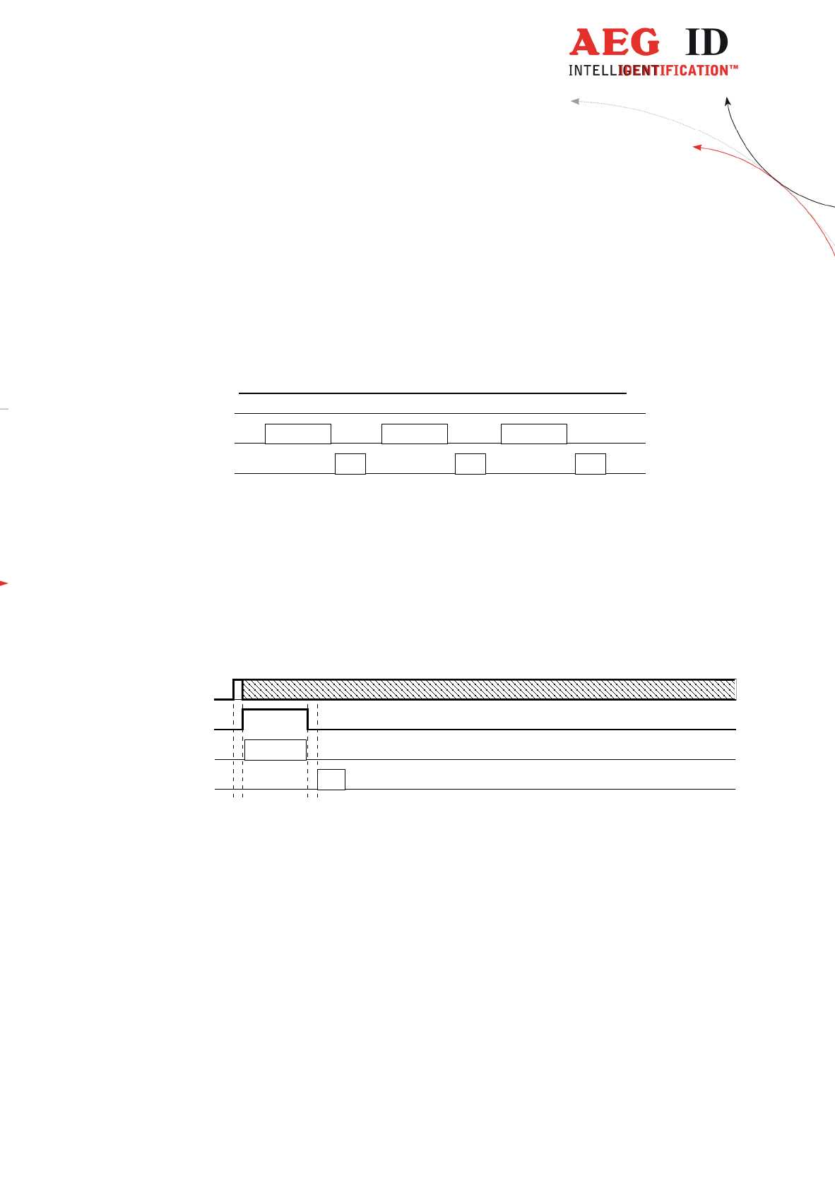
2.2 Operating mode 0 - continuous mode
When operating continuously the exciter is switched on permanently. The reading cycles are initiated peri-
odically.
After an accomplished reading cycle the reading information is evaluated. After that data (either trans-
ponder number or NoRead code) is output to the serial interface.
exciter
processor
interface
reading cycle
ID ID ID
reading cycle reading cycle
Figure 2.1: continuous operation
2.3 Operating mode 1 - running externally triggered
In operation mode 1 the exciter is turned off. As soon as the external triggered signal rises from logic 0
to 1, the exciter is started and a reading process is initiated.
trig_in
processor
interface
exciter
ID
reading cycle
Figure 2.2: external triggering -limitation of the switch period through a successful reading
After a successful reading cycle, the exciter is turned off immediately (irrespective of the trigger signal).
The next reading cycle starts at the next leading edge (0 to 1) of the trigger signal.
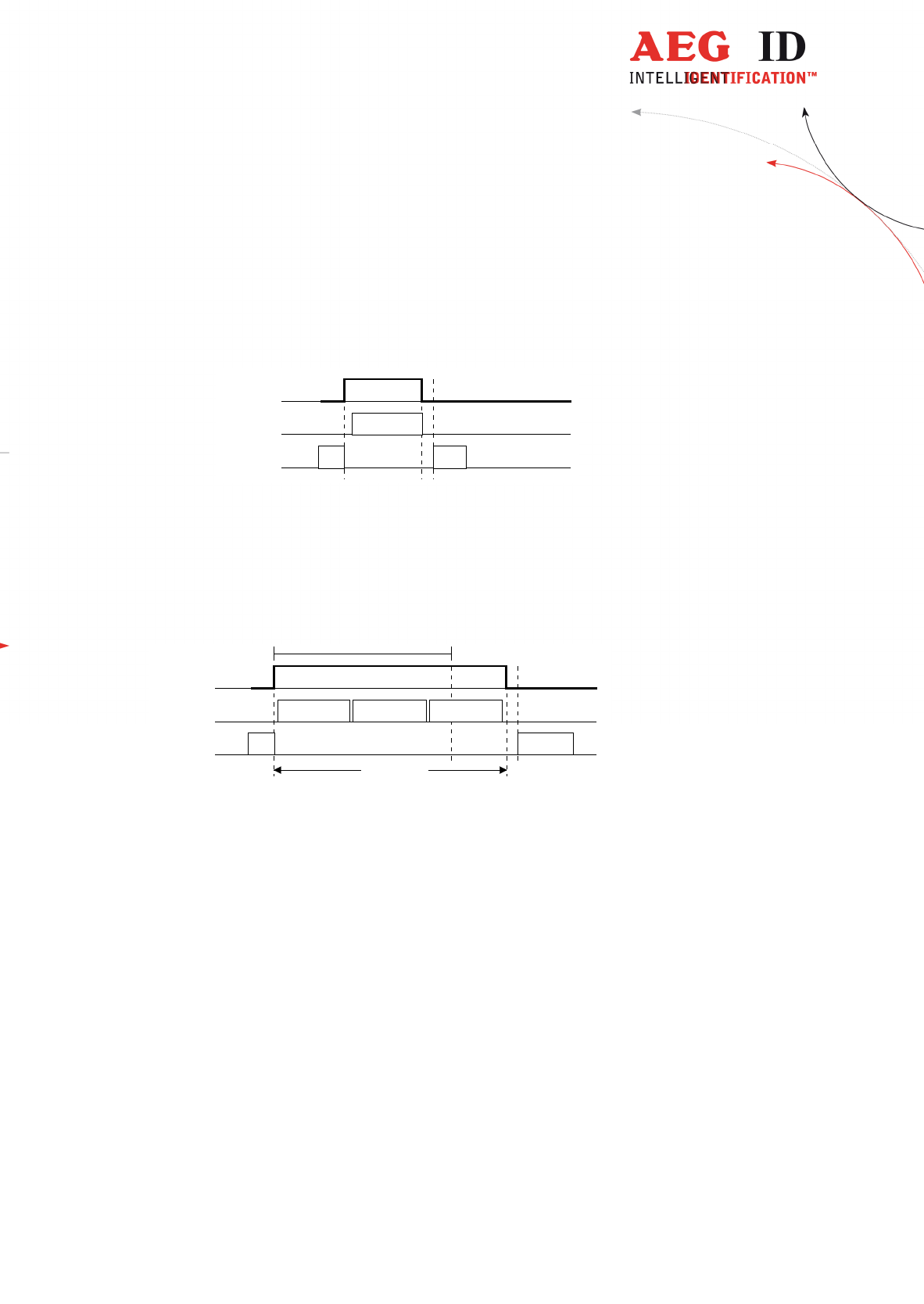
If a reading cycle is not successful, the reading process is controlled by the state of the external trigger
signal: further reading cycles are started as long as either a successful cycle has occurred or the exter-
nal trigger signal is logic 0 again. In the latter case the identification NoRead code is output.

--------------------------------------------------------------------------------7/26--------------------------------------------------------------------------------
trig_in
processor
interface
exciter
NoRead
reading process
reading cycle reading cycle reading cycle
Figure 2.3: external triggering - limitation of the switch period through the Trig_In signal
Please note: In the course of the reading process no NoRead message will be output!
--------------------------------------------------------------------------------8/26--------------------------------------------------------------------------------
2.4 Operating mode 2 - reading triggered by the serial interface
In operating mode 2, the exciter is always turned off. Triggered by the command GT, the exciter is acti-
vated. After successful reading of a transponder number the exciter is turned off automatically.
exciter
processor
interface
reading cycle
ID
GT
Figure 2.4: software triggered reading operation
If the first reading cycle yields no result (NoRead), the on-time of the exciter is limited by the parame-
ter TOR (time out reader): Reading cycles are continuously started until either a transponder is read
successfully or the time span corresponding to the value of the parameter TOR has expired. The reader
will not interrupt the last running readout cycle. If no transponder number has been read, a NoRead is
output.
exciter
processor
interface
TOR
GT
reading process
NoRead
reading cycle reading cycle reading cycle
Figure 2.5: software triggered reading operation with TOR>0
Please note: Within the time span defined by the value of TOR no NoRead will be output on the interface!
3 Protocol format
The command set described in this chapter defines the transfer of data on the serial interface.
The commands consist of a command code and of a parameter value optionally. Commands are termi-
nated by the control character <CR> (13H). The control character terminates the command line.
Command codes and parameters, that means all letters and numerical values, are principally transmitted as
a sequence of ASCII characters (the value 255 (decimal) consequently as 32H, 35H, 35H; the command
RST as 52H, 53H, 54H).
3.1 Echo function
The echo function can be switched on or off.

--------------------------------------------------------------------------------9/26--------------------------------------------------------------------------------
If the echo function is activated using the EC command, every signal sent to the reader is immediately sent
back (echoed) after receipt. Thus the echo function can be used as life indication. If the reader is controlled
by a terminal, the echo function should normally be activated.
If an echo function is not intended, e.g. in automation applications where the reader might be connected to
an PLC, the echo function should be deactivated.
3.2 Entering of commands
The protocol format is as follows
command <SP> parameter <CR>
The space character <SP> separates the commands from the parameter value. The <CR> character
terminates the command line.
For commands without parameter values (e.g. GT or RST) the <SP> character and parameter values
are omitted. The command line is as short as this:
command <CR>.
3.3 Output format
Generally, every input terminated by <CR> is acknowledged by the reader. The following response proto-
cols are different:
3.3.1 Command specific response
After a correct command without parameter value is sent to the reader, the reader answers using a for-
mat, which is specific for the submitted command. Example:
Command: GT <CR>
Output: transponder number <CR> or NoRead-code
2
<CR>
3.3.2 Response to a parameter change
After entering a valid command together with a parameter value, the system answers by sending the pa-
rameter value and <CR>. Example:
Command: MD <SP> 1 <CR>
Output: 1 <CR>
2
see chapter3.10.1

--------------------------------------------------------------------------------10/26--------------------------------------------------------------------------------
After entering an invalid parameter value, the system answers with the corresponding error code (see chap-
ter 3.6 ).
3.3.3 Response to a parameter query
Parameter settings can be queried by sending the command without adding an parameter value. Example:
Command: MD <CR>
Output: 1 <CR>
3.4 Parameters
Generally a command comes with one parameter value at the most. Command code and paramter value
are separated by SP>.
3.4.1 Set of parameters
The ARE K1 is provided with three independent sets of parameters:
• the set of parameters ex work
• the set of parameters specific to the application plus
• the actual set of parameters
The set of parameters ex work enclose all original reader settings. This set is stored in the EPROM and
can’t be changed. The set of parameters specific to the application is stored in an EEPROM. This set de-
fines the configuration after a cold start. The actual set of parameters defines the actual function of the
decoder. It is stored in the RAM.
All changes of the parameter values have an effekt to the actual set of parameters only. This set is tem-
porary, that means all values are lost after switching off the decoder.
Using the VSAVE command (see chapter 4.19) the actual set can be stored permanently as set of pa-
rameters specific to the application. Then all values are loaded back automatically after a cold start.
3.5 Blank input line
If a single <CR> is input, the reader answers with a single <CR>. Example:
Command: <CR>
Output: <CR>

--------------------------------------------------------------------------------11/26--------------------------------------------------------------------------------
Please note: If echo mode is active, a single <CR> forces the reader to output <CR> <CR> (echo plus
output).
3.6 Erroneous entering of commands - error codes
If a command is not entered correctly, the reader sends one of the following error codes:
Wrong command: <NAK> #00 <CR>
Wrong parameter: <NAK> #02 <CR>
3.7 Boot message
After booting the system (cold and warm start) the software version is output as described for the VER
command (see chapter 4.17), if echo is active. If echo is disabled, no boot message will appear.
3.8 Use of capital letters
The standard operating system is not case-sensitive, that means capital- and small letters are treated the
same.
3.9 Line feed
A line feed character <LF> is not sent by the decoder. If the decoder is controlled by a terminal, a line
feed can be added by the terminal software (option: replace CR by CR LF at receipt).
3.10 Output format for the transponder number
The location of the transponder bits in the ASCII characters is shown in Table 3.1:
D38 ... D32 D31 ... D24 D23 ... D16 D15 ... D8 D7 ... D0
ASC9 ASC8 ASC7 ASC6 ASC5 ASC4 ASC3 ASC2 ASC1 ASC0
Table 3.1: data format of the transponder number
0 0 0 0 0 0 0 0 0 0 1 1 1 1 1 0 0 1 1 0 1 1 1 1 0 1 1 1 1 0 1 1 0 0 1 0 0 1 0
00H 1FH 37H BDH 92H
30H 30H 31H 46H 33H 37H 42H 44H 39H 32H
Table 3.2: example of a transponder number

--------------------------------------------------------------------------------12/26--------------------------------------------------------------------------------
The transponder ID 001F37BD92 will be transmitted on the interface using the characters 30H, 30H,
31H, 46H, 33H, 37H, 42H, 44H, 39H, 32H and <CR>.
3.10.1 Output format for the NoRead information
An unsuccessful reading cycle is represented by the NoRead character sequence (see CN command in chap-
ter 4.3). Normally the NoRead is coded by the number FFFFFFFFFF, which can never appear as trans-
ponder code.
Alternativly at the ARE K1 a NoRead information can be output using the error messages <NAK> #09
<CR>. For this the parameter value of CN has to be set to 2
3
.
3.10.2 Output of a reader number
For readers connected by a network the output of an individual reader identification is necessary, to assign
a message with the belonging sender device. This identification can be made activating the RNR function
(see chapter 4.14 - reader number). If the RNR function is active, each reader answer is preceded by a
reader number and a space character as well (i.e 15 <SP>).
4 Command set specification
4.1 ALGO
Algo defines the type of chip used.
Input format: ALGO <SP> Parameter <CR>
Parameter
value
Function
1 Trovan read only
2 PSK
output (example): 1 <CR>
note: After correct parameter setting, Algo defines chip type used.
4.2 BD
The BD command enables the change of the baud rate.
3
not compatible down to ASB 1.0

--------------------------------------------------------------------------------13/26--------------------------------------------------------------------------------
Input format: BD <SP> Parameter <CR>
Parameter
value
Function
0 4800 baud
1 9600 baud
2
4
19200 baud
3 38400 baud
output (example): 2 <CR>
note: The settings are effective after a warm start using the RST command.
4.3 CID
With CID=1 only the first of in succession identical transponder numbers is output on the serial interface.
The possibly following identical transponder numbers are suppressed, as long as no new valid transponder
number is received, processed and output. NoReads do not influence the data filtering
input format: CID <SP> parameter <CR>
Parame-
ter
Function
0 no filter function
1 suppression of repeatedly read IDs
output (example): 0 <CR>
Example: A, B, C are specific different transponder numbers, N is NoRead:
Sequence of reading cycles Output sequence after
filtering with CN=0
and CID=1
Output sequence after
filtering with CN=1
and CID=1
N, N, ......,N, A, A, A, ....A, N,N, ......... N, N, ......,N, A, N, N,
.......
A
N. N, N, A, A, A, N, A, A, B, A, C, C, C, .......
N. N, N, A, N, B, A, C,
.....
A, B, A, C
N, N, B, B, B, B, B, N, N, N, B, B, B, B, N,
N,...
N, N, B, N, N, N, N,
N,...
B
N, N, N, B, B, B, B, B, N, B, B, B, B, N, N,
N, ....
N, N, N, B, N, N, N, N,
....
B
Table 4.1: example for the effect of the CID function
annotation: The internal reference number is cleared at the following conditions:
• after a cold start
• after a warm start
4
default values are underlined
--------------------------------------------------------------------------------14/26--------------------------------------------------------------------------------
• after entering the command line CID <SP> 1 <CR>
This causes that the next transponder code is output definitely.
caution: The filter function CID picks up the results of the complete reading cycles,
while the parameter NID proceeds from the results of single readings! The filter
function CID has effect on the serial interface only. The digital output QR1 is
not effected by CID.
4.4 CN
The CN parameter defines the type of NoRead output.
input format: CN <SP> parameter <CR>
Parameter Function
0 issue NoReads on serial interface using FFFFFFFFFF
1 suppress NoReads on serial interface
2 issue NoReads on serial interface using <NAK> #09 <CR>
5
output (example): 0 <CR>
4.5 DIAG
A self-diagnosis is executed. An antenna test is included.
input format: DIAG <CR>
function: A test of the antenna is executed . After this either the message <NAK> #99
<CR> (o.k.) is output on the interface or the message <NAK> #10 <CR> (an-
ntenna failure).
annotation: With an antenna failure the Error-LED is set.
5
parameter value 2 is not compatible down to ASB 1.0

--------------------------------------------------------------------------------15/26--------------------------------------------------------------------------------
4.6 EC
The EC parameter changes of the echo function setting.
input format: EC <SP> parameter <CR>
Parameter Function
0 echo on
1 echo off
output (example): 0 <CR>
4.7 GT
The reading command code is GT. For details to this function see chapter 2.
input format: GT <CR>
output: Dependent of the parameter settings and the actual antenna input signal, three
different responses are possible in operating mode 2:
• Transponder number, e.g. 001F37BD92 <CR>
• NoRead, e.g. FFFFFFFFFF <CR>
• <CR> as command acknowledge, if a filter function is active, which cut
the transponder code or the NoRead result.
annotation: In mode 2 the GT command triggers a reading process.
In mode 1 the GT command is effectiv too
6
.
In mode 0 the GT command has no effect.
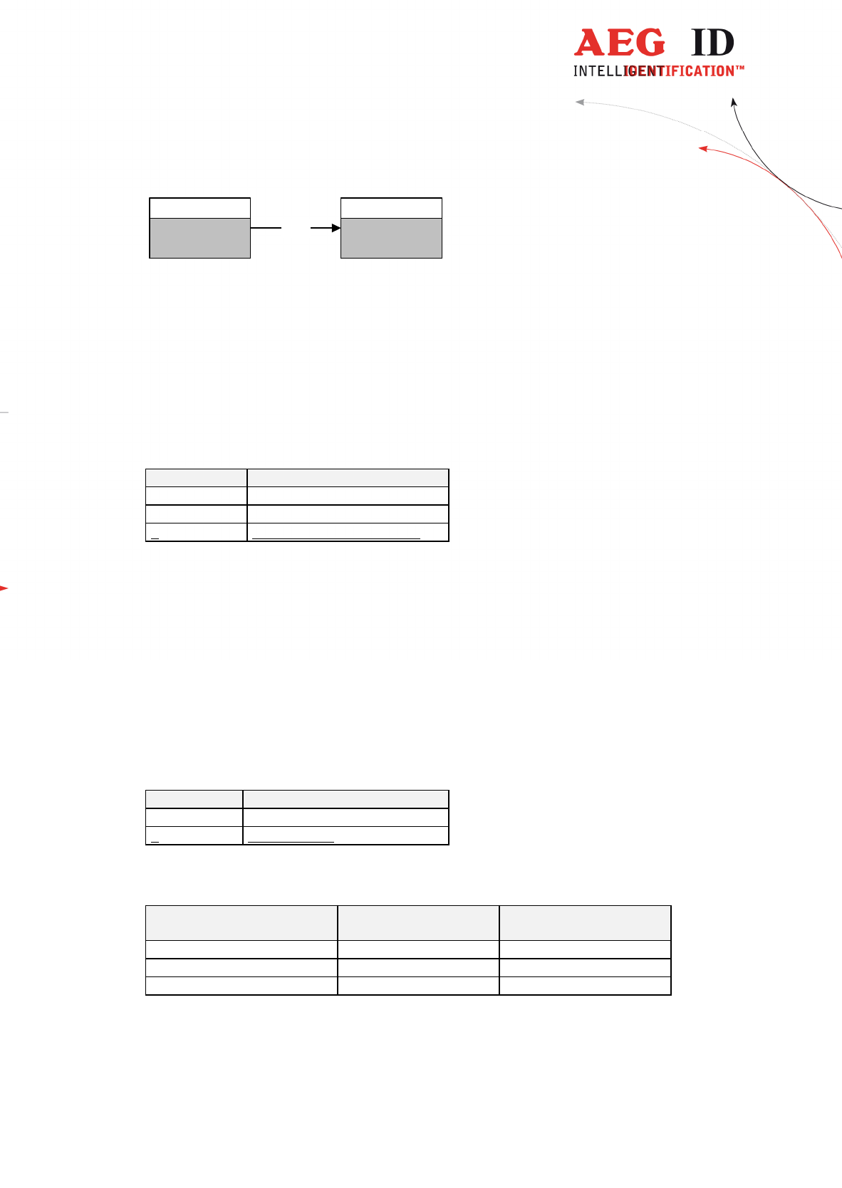
4.8 INIT
With INIT a warm start with default values is executed.
input format: INIT <CR>
output: Version number <CR> if EC=1, otherwise <CR> only
course:
6
not compatible down to ASB 1.0
--------------------------------------------------------------------------------16/26--------------------------------------------------------------------------------
EPROM
set of parameter
ex work
(default values)
RAM
actual set of
parameter
INIT
Figure 4.1: function of INIT
4.9 MD
The command MD changes the operating mode.
input format: MD <SP> parameter <CR>
Parameter Function
0 continuous operation
1 externally triggered
2 triggered via serial interface
output(example): 0 <CR>
4.10 NID
NID specifies the number of identical transponder numbers, which have to appear for the result ”suc-
cessful reading” within a reading cycle. In the setting NID = 1, two successive readings have to show
the same transponder number.
input format: NID <SP> parameter <CR>
Parameter Function
0 one out of one (no effect)
1 two out of two
output (example): 1 <CR>
Sequence of readings Length of the reading
cycle
Result of the reading cycle
NoRead 1 reading NoRead
0000125ED1, 0000125ED1 2 readings 0000125ED1
0000125ED1, 0000126ED1 2 readings NoRead
--------------------------------------------------------------------------------17/26--------------------------------------------------------------------------------
table 4.2: example for a reading cycle with NID=1
4.11 NRD
For improvement of the signal to noise ratio, a number of telegrams can be superimposed. The number
of superimpositions is determined by the value NRD.
input format: NRD <SP> parameter <CR>
Parameter Function
0 no superimposition - evaluation of one telegram only
1 superimposition of 2 telegrams
2 superimposition of 4 telegrams
output (example): 1 <CR>
4.12 QR1
The command QR1 changes the parameters of the digital port QR1.
input format: QR1 <SP> parameter <CR>
Parameter Function
0 port turned off
1 port turned on
2 port controlled by previous reading process
output (example): 0 <CR>
4.13 QN1
The command QN1 changes the parameters for the digital port QN1.
input format: QN1 <SP> parameter <CR>
Parameter Function
0 port turned off
1 port turned on
2 port controlled by previous reading process
output (example): 0 <CR>
--------------------------------------------------------------------------------18/26--------------------------------------------------------------------------------
4.14 RNR
Setting RNR not to 0 activtes the RNR fuction. Then each reader answer is preceded by a reader num-
ber and a space character as well (i.e 15 <SP>).
input format: RNR <SP> parameter <CR>
Parameter Function
0 RNR function not active
1 ... 9 the one-digit reader number and <SP> is
preceded to each reader answer
10 ... 99 the two-digit reader number and <SP> is
preceded to each reader answer
output (example): 99 <CR> after entering RNR 99 <CR>
NAK#02 <CR> after entering RNR 1A <CR>
4.15 RST
With RST a warm start is executed. All changed parameter values (i.e. BD) become effecive. The relays
and error LEDs are cleared.
input format: RST <CR>
output: Version number <CR> if EC=1, otherwise <CR> is output only
4.16 TOR
Timeout for the reader. TOR is used in operation mode 2 as maximum gating time for a reading process
(see chapter 2.4). The length of the maximum gating time results from the equation gating_time = TOR
* TB.
The time constant TB (Time Base) has always the default value 100ms.
input format: TOR <SP> parameter <CR>

--------------------------------------------------------------------------------19/26--------------------------------------------------------------------------------
Parameter
7
Function
0 limits the reading process duration to
exactly one reading cycle
1 Tmax = 100ms
2 Tmax = 200ms
...
5 Tmax = 500ms
...
255 Tmax = 25,5s
output (example): 2 <CR>, this means 200ms.
4.17 VER
The command VER outputs the software version of the reader. The software version is permanently
stored in the program memory together with the firmware.
input format: VER <CR>
output: AEG <SP> ID <SP> - <SP> V1.4E <CR>
4.18 VS
The command VS lists all current parameter settings.
input format: VS <CR>
output (example): EC <SP> 0 <CR>
BD <SP> 2 <CR>
MD <SP> 2 <CR>
.....
4.19 VSAVE
All operating parameters temporarily stored are saved permanently using VSAVE.
input format: VSAVE <CR>
output: ok <CR> oder error message
course:
7
values > 9 are not compatible down to ASB 1.0

--------------------------------------------------------------------------------20/26--------------------------------------------------------------------------------
set of parameter
specific to the
application
actual set of
parameter
RAM
VSAVE
EEPROM
figure 4.2: function of VSAVE
function: While storing the parameter values the EEPROM is tested by „write and ver-
ify“. On EEPROM-error the message <NAK> #03 <CR> is transmitted.

--------------------------------------------------------------------------------21/26--------------------------------------------------------------------------------
5 Description of hardware near functions
5.1 Cold start
After a cold start the system is initialized using the parameter values out of the EEPROM. The indica-
ting elements (relays / LEDs) are cleared.
5.2 Interface to the master
The serial interface permits communication between the reader and a master (e.g. terminal or PC). The ba-
sic configuration of the interface is 19200baud and 8N1 (8 bit, no parity and 1 stop bit). With the com-
mand BD the reader can be set to a different baud rate. Changing the data format (8 data bits, no parity, 1
start- and stop bit) is not possible. The same applies to hardware-handshaking, e.g. Xon/Xoff or RTS/CTS.
5.3 Digital trigger input
For the operating mode 1 - externally triggered - a digital input channel is required. The following logical
function is defined:
5.3.1
Logical level
If the digital input is open (not connected), then it is in the logical state zero (0). By feeding the defined
input voltage the digital input has one-level (1).
5.3.2
Timing characteristics
When triggered externally, the first reading process is initiated by a change from 0 to 1 (leading edge) -
see chapter 2.3.
5.4 Digital trigger outputs
Two specified digital outputs are defined as follows:

--------------------------------------------------------------------------------22/26--------------------------------------------------------------------------------
Output Function
QR1 trigger output - transponder read (QREAD)
QN1 trigger output - NoRead (QNoREAD)
Table 5.1: definition of the digital output channels
5.4.1
Logical level
At rest all digital outputs are logical 0. This means the rest contact is closed and the working contact is
open.
5.4.2
Logical function
The logical function of the digital outputs is determined by the particular parameter setting.
If QR1 = 2 resp. QN1 = 2, the logical function is defined as follows:
After cold- and warm start all trigger outputs are set to logical zero. After processing the reading re-
sult, the corresponding output is set to logical 1 according to Table 5.1. If both trigger outputs QR1
and QN1 are set to parameter value 2, therefore only one of the trigger outputs can be at logical 1 at a
time.
The result of each reading cycle is displayed at the corresponding digital output until the end of the next
reading process.
The data filtering functions for the serial interface (e.g. CN - suppression of the NoRead output or CID)
do not influence on the digital outputs.
5.5 Indicating elements (LEDs)
LED1: on when antenna is operated
LED2: on when last read was not successful
LED3: on when last read was a success
LED4: on as long as the digital input is high
LED5: on when a hardware error was detected
LED6: flashing as long as the reader is powered and the microprocessor is working properly
LED7: on as long as commands were received on the RS 232 interface
LED8: on as long as information is transmitted from the RS.232 interface
LED9: not used
5.6 DIP-switches
In normal condion (ex work) all DIP-switches are set OFF (down).

--------------------------------------------------------------------------------23/26--------------------------------------------------------------------------------
On
1 2 3 4 5 6 7 8
DIP-Switch
If switch 1 is in position ON, the default values (see chapter 3 - firmware) are loaded out of the EPROM at
a cold start (when reader is put in operation).
DIP-switches 2 ... 8 have no function.

--------------------------------------------------------------------------------24/26--------------------------------------------------------------------------------
6 Appendix
6.1 Glossary
Telegram: Sequence of 64 data bits transferred from the transponder to the reader.
Superimposition: Number of superimposed telegrams for an improved signal to noise ratio ad-
justed by the parameter NRD.
Reading: Interval of several telegrams, whose number is fixed by NRD. The result of a
reading is a transponder number or NoRead. In contrast to the reading process
a reading does not appear at an external interface, that means the result is
processed within the reading algorithm only.
NoRead: If it is not possible to determine a transponder number (no header, wrong par-
ity, ...), then the reader operates for the next internal operations with the trans-
ponder number FF FFFF FFFF (Hex) as NoRead information.
NID: This parameter sets the number of readings with identical transponder number,
which have to appear within one reading cycle for the result ”successful reading
cycle”.
Reading cycle: Interval of several readings. The maximum length of intervals is fixed by the
values of NRD and NID. A reading cycle is successful if within the reading cycle
the number of readings specified by NID yields the same result.
Reading process: Interval of several readings. A reading process is started with occurrance of the
trigger condition. The reading process is either terminated by occurrence of a
successful reading cycle or through a break (time out, falling edge of the exter-
nal trigger signal)
8
. At the end of a reading process appears always a result on
the interface
9
.
6.2 list of control characters
Steuerzeichen Hexcode Bezeichnung Funktion
SP 20H space character separates commands from parameters
CR 0DH carriage return terminates command line
NAK 15H negative acknowledge error code
# 23H number sign error number
DEL 7FH delete change of operation mode after a cold
start
table 6.1: List of the control symbols used
8
In operating mode 0 is a reading process equal to a reading cycle.
9
The result will not appear when a data filter suppresses the result (e.g. NoRead suppression).

--------------------------------------------------------------------------------25/26--------------------------------------------------------------------------------
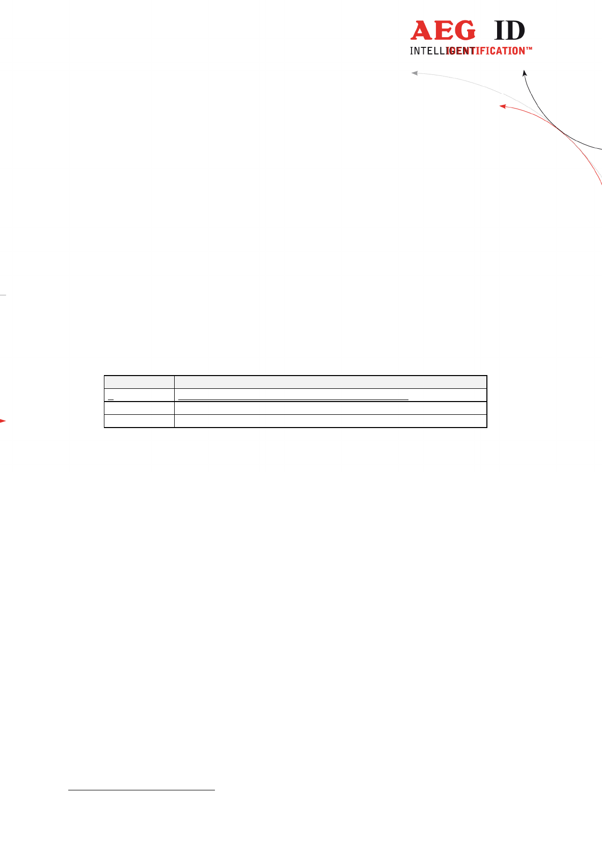
6.3 List of error messages
error number function error-LED
#00 command code not known, wrong code no
#01 stack-error (under- / overflow) no
#02 parameter value not valid no
#03 error in EEPROM no
#04 function not supportet no
#05 reserved no
#06 reserved no
#07 reserved no
#08 reserved no
#09 kein Code gelesen (NoRead) no
#10 antenna error yes
#99 system o.k. (DIAG state messages) no
Table 6.2: List of error messages
6.4 List of system commands
command-
code
function action on interface Compability
with ASB1.0
DIAG diagnosis / state of the reader state or error message no
GT read transponder (get tag) transponder number yes
INIT load basic configuration boot message / <CR> yes
RST warm start boot message / <CR> yes
VER Output version number version number yes
VS Output of all parameter values List of parameters yes
VSAVE store current configuration ok yes
Table 6.3: List of system commands
6.5 List of parameters and default values
com-
mand-
code
function universally
defined
parameters
(ASB 1.0)
valid pa-
rameter
values for
ARE K1
default-values
MD mode of operation 0 .. 2 0 .. 2 2 (triggered by interface)
BD baud rate 0 .. 3 0 .. 3 2 (19200baud)
EC echo 0, 1 0, 1 0 (off)
CN suppression of NoRead 0, 1 0 .. 2
0 (ou
tput FFFFFFFFFF)
CID filter function for multiply read IDs 0, 1 0, 1 0 (filter off)
NID number of identical IDs per reading cycle 0 , 1 0 , 1 1 (two out of two)
NRD superimposition of telegrams 0 .. 2 0 .. 2 1 (two telegrams)
RNR reader identification number - 0 .. 9, 10..
99
0 (not active)

--------------------------------------------------------------------------------26/26--------------------------------------------------------------------------------
QN1 digital output QN1 0 .. 2 0 .. 2 2 (controlled by reading
process)
QR1 digital output QR1 0 .. 2 0 .. 2 2 (controlled by reading
process)
TOR timeout parameter for unsuccessfull reading
0...9 0...255 5 (500ms)
Table 6.4: List of parameters