AEG Identifikationssysteme AREK1-2 RFID Reader User Manual ARE K1 PFB Installation Guide engl 04
AEG Identifikationssysteme GmbH RFID Reader ARE K1 PFB Installation Guide engl 04
UserManual.wiki
>
AEG Identifikationssysteme
>
AREK1 2 User Manual
Inst Guide
Navigation menu
Upload a User Manual
Namespaces
Wiki Guide
HTML
PDF
Info
Views
User Manual
Discussion / Help
Navigation


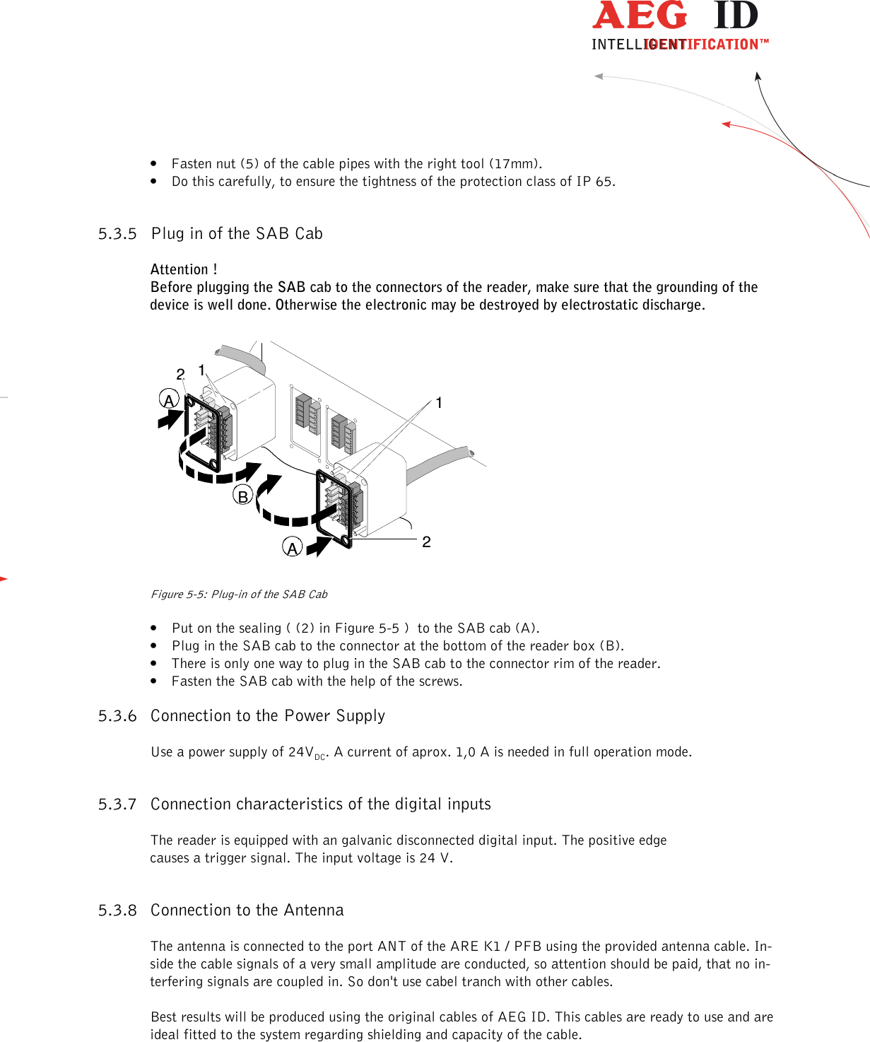
![--------------------------------------------------------------------------------6/18-------------------------------------------------------------------------------- 4 Start-up Procedure Schritt Aufgabe Inhalt Verweis 1 prearrangements read installation manuals carefully - 2 installation mounting, cabeling chapter 5 3 definition of the Profibus-Slave attributes set node adress and termination switch chapter6 4 initial operation connect antenna switch on power supply check power consumption and LEDs chapter7 5 integration into the Profi-bus-network read GSD into the plc, integrate Profibus-Slave with correct slave adress, send telegrams with parameters and config-uration chapter 8 6 implement data transfer between master and slave realise basic function module for data trans-fer see [2] 7 check system send reading command, check reaction chapter 9.2 8 build application realise function modules on the plc -](https://usermanual.wiki/AEG-Identifikationssysteme/AREK1-2/User-Guide-3156783-Page-6.png)
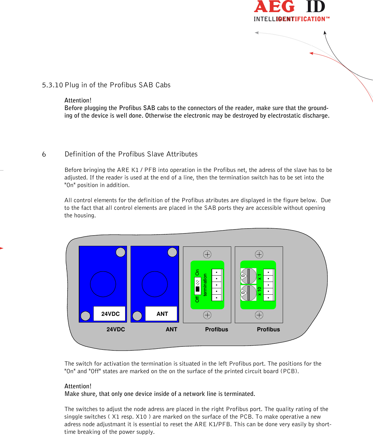
![--------------------------------------------------------------------------------7/18-------------------------------------------------------------------------------- 5 Installation To get the specified reading performance it is necessary to do the installation carefully step by step as it is described in the chapters below. All the work must be done by well educated people. 5.1 Mounting of the Housing The reader box of the ARE K1/PFB has connection ports for: • the antenna [ANT] • the power supply [24VDC] • Profibus input [Profibus] • Profibus output [Profibus] • ground SAB connectorcapsground connectorLED-indicatorstop of the boxbottom of the box24VDCANTModerne elektronischeObjekterkennung und VerfolgungARE K1/PFBBFHID24VDCANTOPERRRXTXANTREADNoREADWRITEProfibusProfibusProfibusProfibus Abbildung 5-1: Configuration of the ARE K1/PFB The reader can be mounted to any other mechanic construction. It is recommended to protect the housing against heavy mechanical interactions. The reader can be mounted on a plate using the holes in the box. To get access to this holes the top of the box has to be demounted. It is recommendable to remove all connecting cables before. The elec-tronic components mounted in the top of the box are connected to the reader electronics in the bottom of the box. All connecting cabels are pluggable at the bottom side. When disconnecting the plugs catch hold of the plug - not of the cable! After mounting the bottom of the box it has to be paid attention to make all connection between top and bottom electronics in the right way again. All plugs are safe to wrong polarity.](https://usermanual.wiki/AEG-Identifikationssysteme/AREK1-2/User-Guide-3156783-Page-7.png)
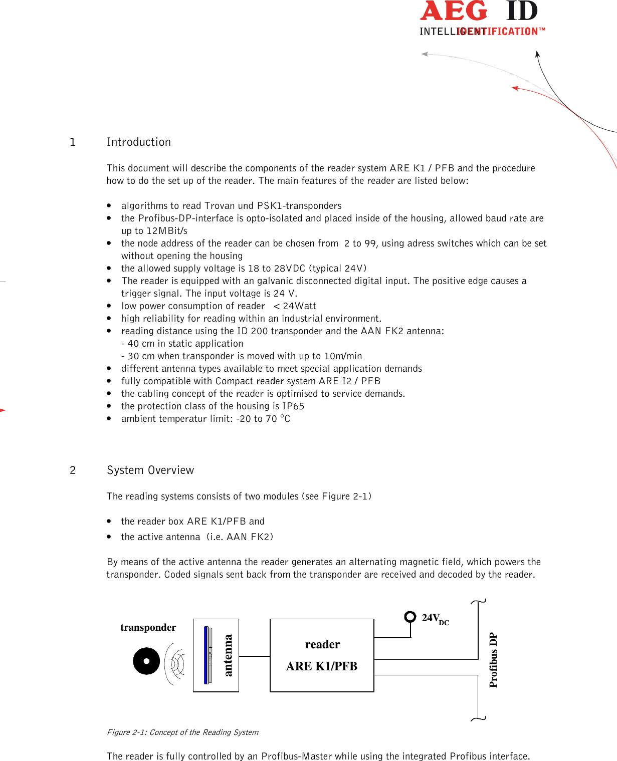
![--------------------------------------------------------------------------------9/18-------------------------------------------------------------------------------- 34516Cable75.3.3 Mounting of the Power Supply Cable The power supply cable must be mounted in following steps: • Prepare the SAB cab according to chapter 5.3.2 • Remove all inner parts from the cable pipe at the SAB cab (1) ( nut (5), pipe(4) and cable fasten-er (3)) (see Figure 5-3) • Put all the removed parts ( nut (5), pipe (4), cable fastener (3)) and the cable pipe of the SAB cab as well (1 to 4) to the cable. Figure 5-3: Arranged Parts for Mounting of the SAB Cab • Remove the outer isolation of the cable at a length of 6cm . • Remove the isolation of the wires at a length of 6 [mm] and stick a covering hull to the litz wire. • Put the cable through the cable pipe. The length of the cable coming out the SAB cab must be long enough to do all further instal-lation steps in an easy way. • Stick the pipe (4) into the cable fastener (3). • Stick the cable fastener (3) into the cable pipe. • Connect the power supply cable into the right places of the MINI-COMBICON-connector (see Fig-ure 5-3 Part (6)). • The pin assignment is shown in the figure below. 24VDCL+US-US ULbluebluebrown( Dig-In - )( Dig-In + )0V / GND+24VDCnot usednot usednot usednot usednot usednot used Figure 5-4: Pin Assignment for Power Supply Cable 5.3.4 Final Assembly of the Cable Pipe • Plug the finished assembled MINI-COMBICON-connector to the SAB cab. Take care of the cor-rect coding ((7) in Figure 5-3) of the connectors. • Pull by and by all the cable back, until the isolation of the cables are near to beginning of the ca-ble pipes.](https://usermanual.wiki/AEG-Identifikationssysteme/AREK1-2/User-Guide-3156783-Page-9.png)
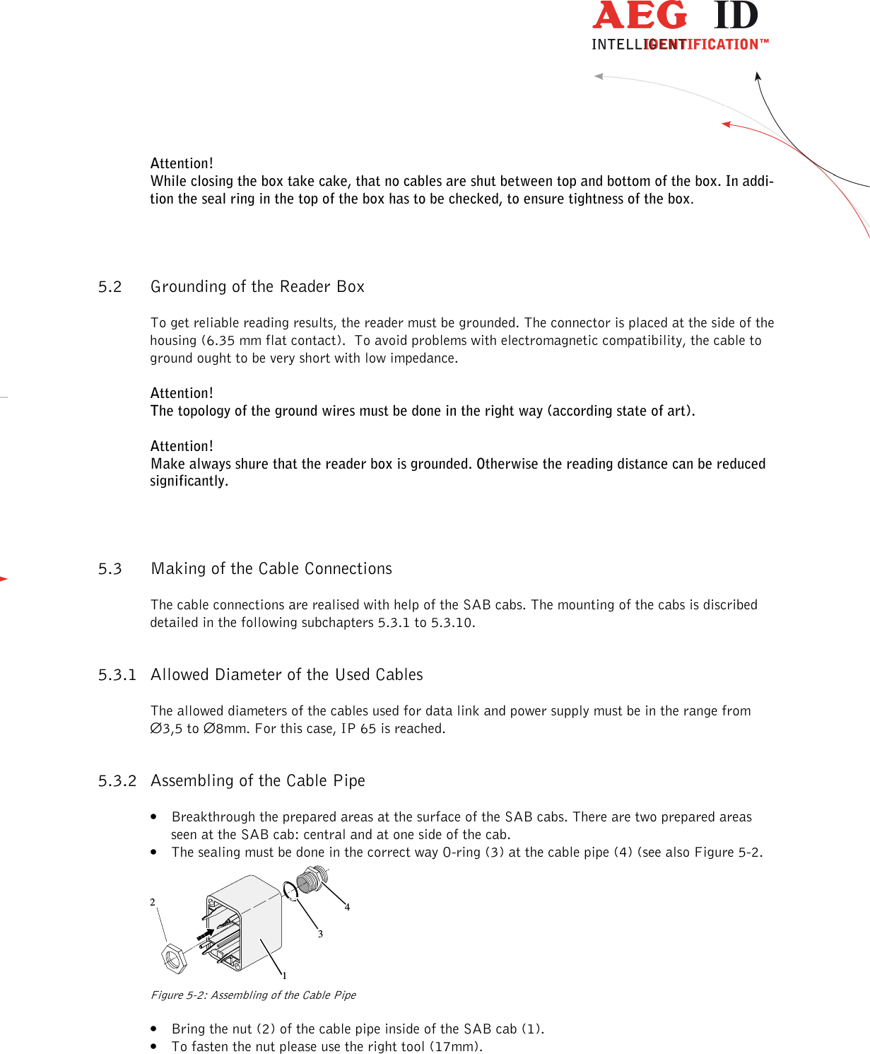
![--------------------------------------------------------------------------------11/18-------------------------------------------------------------------------------- 34516Cable785.3.9 Assembling of the Data Cable (Profibus Network) The connection from the ARE K1 / PFB to the master PLC is made using the interface cable. This must be mounted in following steps: • Prepare the SAB cabs "Profibus" in the same way like subchapter 5.3.2 . • Put all the removed parts ( nut (5), pipe (4), cable fastener (3)) and the cable pipe of the SAB cab as well (1 to 4) to the cable. Figure 5-6: Arranged Parts for Mounting • Remove the outer isolation of the cable at a length of 6 cm. • Unwrap the texture of the shielding and drill it to build up pig tail wire (7). • Stick a covering hull to the pig tail wire. • Put the cable to the cable pipe. The length of the cable coming out the SAB cab must be long enough to do all further installation steps in an easy way. • Remove the isolation of the data wires at a length of 6 [mm]. • drill red litz wire of the data cable and put on a covering hull. • do the same way with the green litz wires. • Stick the pipe (4) into the cable fastener (3). • Stick the cable fastener (3) into the cable pipe. greyProfibusnc+Data ( B )ncshieldncncncncnc-Data ( A )greenredKHJFG Figure 5-7: Pin Assignment for the Profibus-Net Data Cable • Connect the data cables into the right places of the MINI-COMBICON-Connector. • The pin assignment is shown in the Figure 5-7 at top. • Continue according to subchapter 5.3.4](https://usermanual.wiki/AEG-Identifikationssysteme/AREK1-2/User-Guide-3156783-Page-11.png)
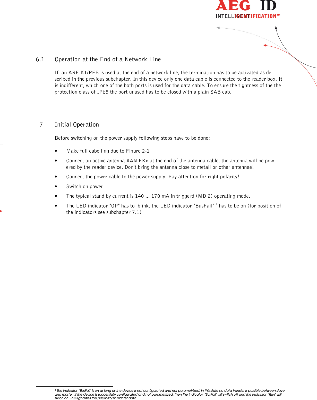
![--------------------------------------------------------------------------------15/18-------------------------------------------------------------------------------- 8.1 Profibus Slave: Configuration and Parametrization The ARE K1 / PFB has one configuration only. Only the seven standard Profibus parameters are de-fined. So it is not necessary, to handle with device specific parameters (User_Prm_data). If the device is parametrized successfully it is ready for data tranfer. The green LED indicator "Run" is on. Attention ! Inside of a network line, it’s not allowed to install more then 32 reader devices. The red LED indicator "BusFail“ has to be off, otherwise an error has occured. The information about the data tranfer protocoll is documented in a special manual [2] : Profibus-DP Communication. 9 Modes of Operating and Commands of the Reader Only one mode of operating is defined for the ARE K1 / PFB: • mode 2 - reading triggered by the PLC This mode is specified in the next subchapter briefly. Beyond that we refer you to the much more de-tailed description in [1] : Set of Commands for ARE K1. 9.1 Set of Commands The reader supports the AEG ID Standardized Command Set (ASB). Due to the specific operating re-quirements in the deterministic Profibus process, the amount of commands and parameters of the ARE K1 / PFB have been reduced as specified below. Listing of commands available in the ARE K1 / PFB: command-code function action on interface DIAG diagnosis / state of the reader state or error message GT read transponder (get tag) transponder number INIT load basic configuration boot message / <CR> RST warm start boot message / <CR> VER Output version number version number VS Output of all parameter values List of parameters VSAVE store current configuration ok Table 9-1: List of all reader commands The ARE K1 / PFB reader has parameters, listed in Table 9.2 below. The parameters NRD and NID should only be changed after consulting the manufacturer.](https://usermanual.wiki/AEG-Identifikationssysteme/AREK1-2/User-Guide-3156783-Page-15.png)
![--------------------------------------------------------------------------------16/18-------------------------------------------------------------------------------- com-mand-code function valid para-meter values default-values ALGO type of transponder 1, 2 1 (trovan read only) NID number of identical IDs per reading cycle 0 , 1 1 (two out of two) NRD superimposition of telegrams 0 .. 2 1 (two telegrams) QN1 digital output QN1 0 .. 2 2 (controlled by reading pro-cess) QR1 digital output QR1 0 .. 2 2 (controlled by reading pro-cess) TOR timeout parameter for unsuccessfull reading 0...255 5 (500ms) Table 9.2: Parameters available for the ARE K1 / PFB 9.2 Operating mode 2 - Reading Triggered by the PLC The PLC sends the command "GT" to trigger a reading process. After finishing the reading process the transponder code or an error code can be read by the PLC. 9.2.1 Principle of Reading a Transponder in mode 2 • Trigger the Reader device using the command "GT "(and <CR> in addition) • Wait for answer of the reader device, polling status bit in response telegram (see manual [2] : Pro-fibus-DP Communication) • Request answer (see manual [2] : Profibus-DP Communication) 10 Warning Notes • This reader is an active electrical transmission system and radiates in the frequency range of ap-proximately 124 kHz. When connecting a defect or a not suited reader to the device the radiated power can be higher than 42dBµA/m (measured at 10 m distance). The operator is responsible that people at risk are not endangered by the device.. • Do not operate the device with open housing, as otherwise there is a danger, that positions with dangerous voltage can be touched. • Never operate the device with defect antenna cables. The antenna cables may conduct dangerous voltages. When disconnecting an antenna cable please assure that the device is turned off and the cable was grounded for a short time before touching it. Otherwise stored energy of the antenna may cause harm. • The reader box has to opened by well educated people only.](https://usermanual.wiki/AEG-Identifikationssysteme/AREK1-2/User-Guide-3156783-Page-16.png)
![--------------------------------------------------------------------------------18/18-------------------------------------------------------------------------------- 12 Documentation, References [1]: Manual: Set of Commands for ARE K1 Specifies all commands, parameters, transfer protocol, error codes and control characters used in the ARE K1. [2]: Manual: Profibus-DP Communication Specifies the data transfer telegram used between PLC and Profibus-slave. 13 Contacts To improve our products, as well as its documentation is our permanent effort. For any questions, feedback or comments please call: Fax: ++49 (0)731-140088-0 Fax: ++49 (0)731-140088-9000 e-mail: sales@aegid.de http:\ www.aegid.de 14 notification of changes change no date description of change version editor • First release 01 18.05.16 • FCC Information 02 MK 22.06.16 • FCC Information correction 03 MK 27.07.16 • FCC Information correction 04 MK](https://usermanual.wiki/AEG-Identifikationssysteme/AREK1-2/User-Guide-3156783-Page-18.png)