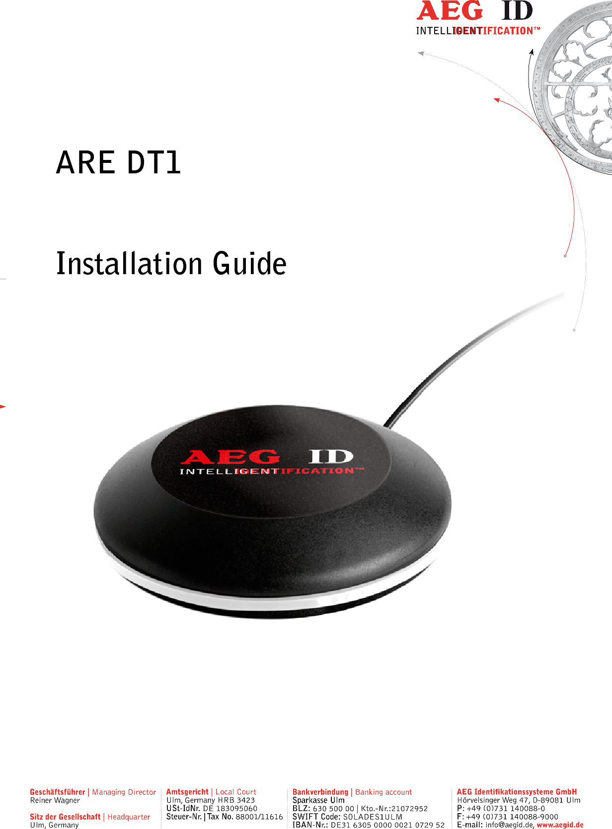
AEG Identifikationssysteme UDT100H RFID Reader User Manual Installation Guide ARE DT1 05

AEG Identifikationssysteme GmbH RFID Reader Installation Guide ARE DT1 05

user manual

        ARE DT1  Installation Guide
                 --------------------------------------------------------------------------------2/45--------------------------------------------------------------------------------      1 INTRODUCTION ............................................................................................................ 5 2 STARTUP AND TESTING THE READER DT1 .............................................................. 6 3 AEG ID INSTRUCTION SET .......................................................................................... 6 3.1 General ..................................................................................................................................................... 6 3.1.1 Entering instuctions ........................................................................................................................... 7 3.1.2 Output format .................................................................................................................................... 7 3.1.2.1 Instruction specific output ........................................................................................................... 7 3.1.2.2 Output after changing a parameter .............................................................................................. 7 3.1.2.3 Output at parameter query ........................................................................................................... 8 3.1.3 Blank instuction ................................................................................................................................. 8 3.1.4 Incorrect instruction / error codes ....................................................................................................... 8 3.1.5 Upper and lower case ....................................................................................................................... 10 3.1.6 Linefeed ........................................................................................................................................... 10 3.2 Instructions for the hardware settings...................................................................................................... 11 3.2.1 BD – baudrate .................................................................................................................................. 11 3.2.2 HF – radio frequency ........................................................................................................................ 11 3.2.3 HID – human interface device/keyboard ............................................................................................ 11 3.2.4 KL – keyboard language ................................................................................................................... 12 3.2.5 RE – read EEPROM ........................................................................................................................ 13 3.2.6 LED – LED control .......................................................................................................................... 13 3.2.7 RST – reset ...................................................................................................................................... 14 3.2.8 WE – write EEPROM ...................................................................................................................... 15 3.2.9 VER – version .................................................................................................................................. 15 3.3 Instructions for reading settings .............................................................................................................. 16 3.3.1 CE – convert error code .................................................................................................................... 16 3.3.2 CID – suppression of ID Codes .......................................................................................................... 16 3.3.3 CN – suppression of No Reads .......................................................................................................... 17 3.3.4 INIT – initialization ......................................................................................................................... 18 3.3.5 LAA – LED automatic activity .......................................................................................................... 18 3.3.6 MC – mirror code ............................................................................................................................. 18 3.3.7 RA – resend last answer .................................................................................................................... 19 3.3.8 TSC – time show code ...................................................................................................................... 19 3.3.9 TOR – maximum reading time .......................................................................................................... 19 3.3.10 SI – set iso standard ......................................................................................................................... 20 3.3.11 VSAVE – variables save ................................................................................................................... 20 3.3.12 VS – variables show ......................................................................................................................... 20 3.4 General reading instructions .................................................................................................................... 21 3.4.1 GA – get active ................................................................................................................................. 21 3.4.2 GT – get tag ..................................................................................................................................... 21 3.4.3 HD – halt detected code .................................................................................................................... 22 3.4.4 MD – mode of operation ................................................................................................................... 22
                 --------------------------------------------------------------------------------3/45--------------------------------------------------------------------------------  3.4.5 RD – read page ................................................................................................................................ 23 3.4.6 RDM – read page manual ................................................................................................................. 24 3.4.7 WD – write page .............................................................................................................................. 25 3.4.8 WDM – write page manual ............................................................................................................... 26 3.5 Mifare instructions .................................................................................................................................. 27 3.5.1 AC – anticollision ............................................................................................................................. 27 3.5.2 AC2 – anticollision level 2 ................................................................................................................ 27 3.5.3 KM – key mode ................................................................................................................................ 27 3.5.4 KT – key type ................................................................................................................................... 27 3.5.5 LOG – transponder log in .................................................................................................................. 28 3.5.6 PBU – purse backup ......................................................................................................................... 28 3.5.7 PDC – purse decrement .................................................................................................................... 29 3.5.8 PIC – purse increment ...................................................................................................................... 30 3.5.9 PIV – purse init value ....................................................................................................................... 31 3.5.10 PRV – purse read value .................................................................................................................... 31 3.5.11 RQ – request .................................................................................................................................... 32 3.5.12 SE – select ....................................................................................................................................... 32 3.5.13 SE2 – select level 2 .......................................................................................................................... 32 3.5.14 WK – write key ................................................................................................................................ 33 3.6 ISO 15693 instructions............................................................................................................................ 34 3.6.1 AFI – application family identifier .................................................................................................... 34 3.6.2 BS – block size ................................................................................................................................. 34 3.6.3 GMS – get multiple block security .................................................................................................... 34 3.6.4 GS – get system information ............................................................................................................. 35 3.6.5 LA – lock AFI .................................................................................................................................. 35 3.6.6 LD – lock data ................................................................................................................................. 35 3.6.7 LDS – lock DSFID ........................................................................................................................... 36 3.6.8 RTR – reset to ready ........................................................................................................................ 36 3.6.9 SF – set flag .................................................................................................................................... 36 3.6.10 WA – write AFI ............................................................................................................................... 37 3.6.11 WDS – write DSFID ......................................................................................................................... 37 4 READER EEPROM ORGANISATION ........................................................................... 38 4.1 EEPROM overview ................................................................................................................................. 38 5 OPERATING MODES OF THE READER ...................................................................... 39 5.1 MD 2 - Triggered by an software command ............................................................................................. 39 5.2 MD 0 - Continuous Reading ..................................................................................................................... 40 6 INSTRUCTIONS .......................................................................................................... 41 7 FCC INFORMATION .................................................................................................... 42 8 CONVERTING DECIMAL TO HEXADECIMAL ............................................................ 43 9 HOTLINE ..................................................................................................................... 45
                 --------------------------------------------------------------------------------4/45--------------------------------------------------------------------------------  10 REVISIONS .............................................................................................................. 45
                 --------------------------------------------------------------------------------5/45--------------------------------------------------------------------------------  1 Introduction This document describes the RFID-reading device ARE DT1 and the set-up procedure. The main features of the reader are listed below: • integrated USB interface selectable either communications port (similar RS232) or HID • USB powered (no external supply voltage necessary)  • compact design
                 --------------------------------------------------------------------------------6/45--------------------------------------------------------------------------------  2 Startup and testing the reader DT1 • Connect the reader with the USB interface from your notebook or pc • In the device manager there will appear a new device (Silicon Labs CP210x USB to UART Bridge) • In the brackets you see the port number of the device (e.g. COM5) • Open the “Demo Terminal“ on the CD • Open the menu “Settings” • You have to set the following settings: baud rate 19200 baud, 8 data bits, no parity, 1 stop bit, no flow control. • Send the command „VER <CR>“ to the reader. The reader answers with the actual firmware version (e.g. AEG ID Multi-ISO V2.034). • Send the command „SI <SP> 0 <CR>“ if you want to read a ISO 14443A transponder. If you want to read a ISO 15693 transponder you have to send the command „SI <SP> 1 <CR>“. • Send the command “MD <SP> 0 <CR>” to the reader. The reader sends No Read messages (XXXXXXXX), while there is no transponder in the antenna field available. If there is a tran-sponder present in the antenna field the reader sends its serial.  3 AEG ID instruction set 3.1 General The command set described below defines the transfer of data on the serial interface. The commands consist of a command code and optionally of a parameter value. Commands are ter-minated by the control character <CR> (0Dh). The control character serves as command line termi-nator. Command codes and parameters,including all letters and numerical values, are principally transmit-ted as a sequence of ASCII characters (the value 255 (decimal) consequently as 32H, 35H, 35H; the command RST as 52H, 53H, 54H). All numbers (e.g. sectors, blocks) are in the hexadecimal format (see chapter 9).
                 --------------------------------------------------------------------------------7/45--------------------------------------------------------------------------------  With the command CS you can change to the alternative instruction set. If the reader is set to alter-native instruction set, you can change back to the AEG ID instruction set via the command AEG (see chapter 5.3.3).  3.1.1 Entering instuctions The protocol format is as follows Command <SP> parameter <CR>  The space character <SP> separates commands from parameters and the <CR> character acts as command line terminator. For commands without parameter values (e.g. GT ) the <SP> character and parameter values are omitted. The command line is as short as this: Command <CR>  3.1.2 Output format Generally, every input terminated by <CR> is acknowledged by the reader. The following response protocols are different: 3.1.2.1 Instruction specific output After entering a valid command without a parameter value, the system answers by sending the param-eter value and <CR>. Example: Command:  GT <CR> Output: Transponder number or No Read <CR> 3.1.2.2 Output after changing a parameter After entering a valid command together with a parameter value, the system answers by sending the parameter value and <CR>. Example: Command:  MD <SP> 2 <CR> Output:   2 <CR>
                 --------------------------------------------------------------------------------8/45--------------------------------------------------------------------------------  After entering an invalid parameter value, the system answers with the corresponding error code. Error message: Command:  MD <SP> 4 <CR> Output:  NAK <SP> #02 <CR>  3.1.2.3 Output at parameter query Parameter settings can be queried by sending the command without adding a parameter value. Exam-ple:  Command:  MD <CR> Output:   2 <CR>  3.1.3 Blank instuction If a single <CR> is input, the reader answers with a single <CR>. Example:  Command:  <CR> Output:   <CR>  3.1.4 Incorrect instruction / error codes If a command is not entered correctly, the reader sends one of the following error codes: ERROR CODE  MEANING NAK #00 <CR>  unknown command NAK #02 <CR>  wrong parameter NAK #03 <CR>  EEPROM error NAK #04 <CR>  wrong transponder type NAK #05 <CR>  buffer overflow NAK #06 <CR>  not logged in
                 --------------------------------------------------------------------------------9/45--------------------------------------------------------------------------------  NAK #08 <CR>  wrong password NAK #10 <CR>  antenna failure NAK #11 <CR>  anticollision error level 1 NAK #12 <CR>  anticollision error level 2 NAK #13 <CR>  select error level 1 NAK #14 <CR>  select error level 2 NAK #15 <CR>  transceiver IC error NAK #16 <CR>  not acknowlegde NAK #17 <CR>  no valid value block NAK #18 <CR>  EEPROM full NAK #19 <CR>  code already saved in EEPROM NAK #20 <CR>  code not in EEPROM NAK #21 <CR>  wrong standard NAK #22 <CR>  wrong transpondercode length NAK #23 <CR>  transpondercode length and transponder don’t match NAK #24 <CR>  data is not multiple of the block size NAK #25 <CR>  data length shorter than block size NAK #26 <CR>  no communication to AMP NAK #27 <CR>  select error level 3 NAK #28 <CR>  anticollision error level 3 NAK #40 <CR>  ISO 15693 error 01h: command not supported NAK #41 <CR>  ISO 15693 error 02h: command not recognized NAK #42 <CR>  ISO 15693 error 03h: option not supported NAK #43 <CR>  ISO 15693 error 0Fh: unknown error (default) NAK #44 <CR>  ISO 15693 error 10h: block does not exist NAK #45 <CR>  ISO 15693 error 11h: block already locked NAK #46 <CR>  ISO 15693 error 12h: block cannot be changed (locked) NAK #47 <CR>  ISO 15693 error 13h: not successfully programmed NAK #48 <CR>  ISO 15693 error 14h: not successfully locked NAK #49 <CR>  ISO 15693 error A0h-DFh: custom error codes NAK #50 <CR>  all other ISO 15693 errors: RFU XXXXXXXX <CR>  no read ACK  no error/acknowledge
                 --------------------------------------------------------------------------------10/45--------------------------------------------------------------------------------  3.1.5 Upper and lower case The instruction set isn’t case-sensitiv. 3.1.6 Linefeed The reader does never send a linefeed. If you use a terminal program it can add the linefeed. You have to choose the option “displace CR with CR LF”.
                 --------------------------------------------------------------------------------11/45--------------------------------------------------------------------------------  3.2 Instructions for the hardware settings 3.2.1 BD – baudrate The command BD enables the change of the baud rate. The settings are directly effective. Input format:  BD <SP> parameter <CR> Output (example):  2 <CR> Parameter:  PARAMETER  FUNCTION 0  4800 baud 1  9600 baud 2  19200 baud 3  38400 baud 4  57600 baud 5  115200 baud 3.2.2 HF – radio frequency With the command HF you can switch the antenna field on and off. Input format:  HF <SP> parameter <CR> Output (example):  1 <CR> Parameter: PARAMETER  FUNCTION 0  off 1  on 3.2.3 HID – human interface device/keyboard The command switches the interface ether to HID or RS232 emulation. Input format:  HID <SP> parameter <CR>
                 --------------------------------------------------------------------------------12/45--------------------------------------------------------------------------------  Output (example):  0 <CR> Parameter:  PARAMETER  FUNCTION 0  RS232 emu-lation 1  HID inter-face, key-board  You have to unplug the device and plug the device in again to use the new setting. Don’t forget to use the command VSAVE to save the new setting. If the reader is in HID mode, you can not send any commands to the device. Because of that you have to use the Set-Up card – interface to switch the reader back from HID mode to serial interface mode. 1. Plug out the reader 2. Place card no reader 3. Plug in reader into USB-port 4. Wait for the beep tone from reader 5. Plug out reader 6. Remove card from reader  3.2.4 KL – keyboard language With the command KL you can configure the language of the keyboard in HID mode. Input format:  KL <SP> parameter <CR> Output (example):  07 <CR> Parameter:  PARAMETER  FUNCTION 07  german
                 --------------------------------------------------------------------------------13/45--------------------------------------------------------------------------------  09  englisch 0A  spanish 0C  french 10  italien 13  dutch 16  portuguese 4B  canadian  3.2.5 RE – read EEPROM You can read out the internal EEPROM with the RE command. Input format:  RE <SP> parameter <CR> Output (example):  FF <CR> Parameter: PARAMETER  FUNCTION 0000h..079Fh  address  3.2.6 LED – LED control With the command LED you can control the LED ring of the ARE DT1.  Input format:  LED <SP> parameter <CR> Output (example):  1 <CR> Parameter: PARAMETER  FUNCTION 0  off 1  on 2  Buzzer beeps, LEDs flash final state =initial state
                 --------------------------------------------------------------------------------14/45--------------------------------------------------------------------------------  3.2.7 RST – reset With the command RST the reader does a warmstart and loads the saved settings from the internal EEPROM. The antenna field is off after the reset. Input format:  RST <CR> Output (example):  ACK <CR>
                 --------------------------------------------------------------------------------15/45--------------------------------------------------------------------------------  3.2.8 WE – write EEPROM Using the command WE you can write one byte to the internal EEPROM. Input format:  WE <SP> parameter 1 <SP> parameter 2 <CR> Output (example):  FF <CR> Parameter: PARAMETER 1  FUNCTION 0005h..079Fh  address  PARAMETER 2  FUNCTION 00h..FFh  data  3.2.9 VER – version With the command VER the reader sends the actual firmware version. Input format:  VER <CR> Output (example):  AEG ID V1.22 <CR>
                 --------------------------------------------------------------------------------16/45--------------------------------------------------------------------------------  3.3 Instructions for reading settings 3.3.1 CE – convert error code With CE=1 the reader sends no error  codes, except the  no read  error, during the  md0 mode or the commands Get Tag.  With CE=2 the reader sends the normal no read error (XXXXXXXX) if there is an error with the se-lect or anticollision. This command has only effect in the ISO 14443A standard. Input format:  CE <SP> parameter <CR> Output (example):  0 <CR> Parameter: PARAMETER  FUNCTION 0  No suppression 1  Suppression of error codes 2  Replacement with XXXXXXXX  3.3.2 CID – suppression of ID Codes In the MD0 mode with CID=1 only the first of in succession identical transponder numbers is output on the serial interface. The possibly following identical transponder numbers are suppressed, as long as no new valid transponder number is received, processed and output. The get tag command is not influenced by this command. NoReads do not influence the data filtering.  Input format:  CID <SP> parameter <CR> Output (example):  0 <CR> Parameter: PARAMETER  FUNCTION 0  No suppression 1  Suppression of equal transponder numbers  Example: A, B, C are different transponder codes, N is NoRead error code:
                 --------------------------------------------------------------------------------17/45--------------------------------------------------------------------------------     Sequence of reading cycles  Output sequence after filtering with CN=0 und CID=1 Output sequence after filtering with CN=1 und CID=1 N, N, ......,N, A, A, A, ....A, N,N, ......... N, N, ......,N, A, N, N, ....... A N. N, N, A, A, A, N, A, A, B, A, C, C, C, ....... N. N, N, A, N, B, A, C, ..... A, B, A, C  The settings are directly effective. Note:  The internal reference number is deleted in the following conditions:  • after a cold start • after a warm start (command line RST <CR>) • after entering the command line CID <SP> 1 <CR> This causes that the next transponder code is output definitely. Note: The filter function CID picks up the results of the complete reading cycles! The filter function CID has effect on the serial interface only.  3.3.3 CN – suppression of No Reads Through  the  setting  CN=1  the  NoRead  results  after  a  get  tag  command  or  in  MD0  mode  are  sup-pressed on the serial interface. Input format:  CN <SP> parameter <CR> Output (example):  0 <CR> Parameter: PARAMETER  FUNCTION 0  No suppression 1  Suppression of equal transponder numbers
                 --------------------------------------------------------------------------------18/45--------------------------------------------------------------------------------  3.3.4 INIT – initialization With the command INIT all paramters of this command set are set to the default values. After that you can save the settings with the command VSAVE.  Input format:  INIT <CR> Output (example):  ACK <CR> 3.3.5 LAA – LED automatic activity The leds can be controlled by the reader or over the interface. You can set it up with the command LAA. If the LEDs are controlled by the reader, the reader beeps and flashes after successful reading and writ-ing.  Input format:  LAA <SP> parameter <CR> Output (example):  0 <CR> Parameter: PARAMETER  FUNCTION 0  manual controlling 1  controlled by reader  3.3.6 MC – mirror code With this command you can change the output order of the bytes from a transpondercode.  Input format:  MC <SP> parameter <CR> Output (example):  0 <CR> Parameter: PARAMETER  FUNCTION 0  normal sequence 1  mirrored sequence
                 --------------------------------------------------------------------------------19/45--------------------------------------------------------------------------------  3.3.7 RA – resend last answer The command RA resends the last answer sent by the reader.  Input format:  RA <CR> Output (example):  0 <CR> 3.3.8 TSC – time show code With the command TSC you can define the time in ms, after that the transpondercode is shown again, when the CID parameter is set to 1. If TSC is 00, the code is not shown a second time.  Input format:  TSC <SP> parameter <CR> Output (example):  00 <CR> PARAMETER  FUNCTION 00  TSC is not active 01..FF  TSC time in ms  3.3.9 TOR – maximum reading time TOR is the timeout time for the reader. TOR is used in operation mode 2 as maximum gating time for a reading process. The length of the maximum gating time results from the equation gating_time = TOR * TB. The time constant TB (time base) has always the default value 100ms.  Input format:  TOR <SP> parameter <CR> Output (example):  05 <CR> Parameter:  PARAMETER  FUNCTION
                 --------------------------------------------------------------------------------20/45--------------------------------------------------------------------------------  00h  limits the reading process duration of exactly one reading cycle 01h..FFh  limits the reading process duration to maximum 1..256 times TB 3.3.10 SI – set iso standard With this command you can switch the iso standard of the reader.  Input format:  SI <SP> parameter <CR> Output (example):  0 <CR> Parameter: PARAMETER  FUNCTION 0  ISO 14443A 1  ISO 15693 3.3.11 VSAVE – variables save With the command VSAVE the following parameters are saved to the internal EEPROM: AFI2, BD, BS, CE1, CID, CN, HID, KL, KM1, KT1, LAA, LED, MC, MD, SF, SI, TOR, TSC  Input format:  VSAVE <CR> Output (example):  ACK <CR> 1 just available in the ISO 14443A standard 2 just available in the ISO 15693 standard 3.3.12 VS – variables show With the command VS the reader shows the settings of the following parameters: AFI2, BD, BS, CE1, CID, CN, HID, KL, KM1, KT1, LAA, LED, MC, MD, SF, SI, TOR, TSC  Input format:  VS <CR> Output (example):  BD <SP> 0 <SP>
                 --------------------------------------------------------------------------------21/45--------------------------------------------------------------------------------    … Note: The function VS shows just the settings that are used in the actual ISO standard. 1 just available in the ISO 14443A standard 2 just available in the ISO 15693 standard 3.4 General reading instructions 3.4.1 GA – get active The command GA causes one reading cycle. There are different cycles for different transpondertypes. This command is only available in the ISO 14443A standard. Mifare 4 byte UID:    request (REQA)         anticollision         select Mifare 7 byte UID:    request (REQA)         anticollision level 1         select 1         anticollision level 2         select 2 The reader answers the UID of an active (non halt) transponder. Input format:    GA <CR> Output (example):  625E562A <CR> 3.4.2 GT – get tag With the command GT you select a transponder. The command GT causes one reading cycle. There are different cycles for different transpondertypes. Mifare 4 byte UID:  request (WUPA)         anticollision         select
                 --------------------------------------------------------------------------------22/45--------------------------------------------------------------------------------  Mifare 7 byte UID:  request (WUPA)         anticollision level 1         select 1         anticollision level 2         select 2 ISO 15693:      inventory The reader answers the UID of a transponder. Input format:    GT <CR> Output (example):  625E562A <CR> 3.4.3 HD – halt detected code The command HD mutes the last selected transponder. Input format:    HD <CR> Output (example):  ACK <CR> 3.4.4 MD – mode of operation There a two modes of operation available. It is possible, that the reader reads constantly or triggered by an instruction. Input format:    MD <SP> parameter <CR> Output (example):  2 <CR> Parameter: PARAMETER  FUNCTION 0  constant reading mode 2  single reading mode
                 --------------------------------------------------------------------------------23/45--------------------------------------------------------------------------------   3.4.5 RD – read page With the command RD you can read out a page of the transponder. The command executes internally the commands get tag, if using mifare 1K/4K log in (with the key attuned to KM) and the reading command. Input format mifare 1K/4K:      RD <SP> parameter 1 <SP> parameter 2 <CR> Input format ultralight:      RD <SP> parameter 2 <CR> Input format ISO 15693 one block:    RD <SP> parameter 2 <CR> Input format ISO 15693 multiple blocks:  RD <SP> parameter 2 <SP> parameter 3 <CR> Output:           parameter 4 <CR> Parameters: PARAMETER 1  FUNCTION 1 or 2 characters  sector  PARAMETER 2  FUNCTION 1 or 2 characters  block/start block  PARAMETER 3  FUNCTION 1 or 2 characters  end block  PARAMETER 4  FUNCTION 32 characters  data (mifare 1K/4K) 8 characters  data (ultralight) up to 64 charac-ters data (ISO 15693)  Note:  The  ISO  15693  regulates  just  the  maximum  length  of  one  block.  If  there  is  no  information about the block size available in the ISO 15693 transponder, you can set this value with the command “BS - block size” (chapter 3.6.2).
                 --------------------------------------------------------------------------------24/45--------------------------------------------------------------------------------  3.4.6 RDM – read page manual With the command RDM you can read out a page of the transponder. The reading command is executed single. You have to do a get tag first. If you are using a mifare standard 1K/4K you have to log in, too. Input format mifare 1K/4K:      RD <SP> parameter 1 <SP> parameter 2 <CR> Input format ultralight:      RD <SP> parameter 2 <CR> Input format ISO 15693:      RD <SP> parameter 2 <CR> Input format ISO 15693 multiple blocks:  RD <SP> parameter 2 <SP> parameter 3 <CR> Output:           parameter 4 <CR> Parameters: PARAMETER 1  FUNCTION 1 or 2 characters  sector  PARAMETER 2  FUNCTION 1 or 2 characters  block/start block   PARAMETER 3  FUNCTION 1 or 2 characters  end block  PARAMETER 4  FUNCTION 32 characters  data (mifare 1K/4K) 8 characters  data (ultralight) up to 64 charac-ters data (ISO 15693)  Note:  The  ISO  15693  regulates  just  the  maximum  length  of  one  block.  If  there  is  no  information about the block size available in the ISO 15693 transponder, you can set this value with the command “BS - block size” (chapter 3.6.2).
                 --------------------------------------------------------------------------------25/45--------------------------------------------------------------------------------  3.4.7 WD – write page With the command WD you write one page to the transponder. The command executes internally the commands get tag, log in (with the key attuned to KM) and the writing command.  Input format mifare 1K/4K:  WD <SP> parameter 1 <SP> parameter 2 <SP> parameter 3 <CR> Input format ultralight:    WD <SP> parameter 2 <SP> parameter 3 <CR> Input format ISO 15693:    WD <SP> parameter 2 <SP> parameter 3 <CR> Output (example):      ACK <CR> Parameters: PARAMETER 1  FUNCTION 1 or 2 characters  sector  PARAMETER 2  FUNCTION 1 or 2 character  block  PARAMETER 3  FUNCTION 32 characters  mifare 1K/4K 8 characters  ultralight up to 32 charac-ters ISO 15693  Note: The ISO 15693 regulates just the maximum length of one block. With the write instruction you can write multiple blocks at once. The datalenght has to be at least the block size or a multiple of the block size. If  there  is no  information  about the  block size  available in the  ISO 15693 transponder, you can set this value with the command “BS - block size” (chapter 3.6.2).
                 --------------------------------------------------------------------------------26/45--------------------------------------------------------------------------------  3.4.8 WDM – write page manual With the command WDM you write one page to the transponder. The writing command is executed alone. You have to select the transponder first. If you are using a mifare standard 1K/4K you have to log in, too.  Input format mifare 1K/4K:  WD <SP> parameter 1 <SP> parameter 2 <SP> parameter 3 <CR> Input format ultralight:    WD <SP> parameter 2 <SP> parameter 3 <CR> Input format ISO 15693:    WD <SP> parameter 2 <SP> parameter 3 <CR> Output (example):      ACK <CR> Parameters: PARAMETER 1  FUNCTION 1 or 2 characters  sector  PARAMETER 2  FUNCTION 1 or 2 characters  block   PARAMETER 3  FUNCTION 32 characters  mifare 1K/4K 8 characters  ultralight up to 32 charac-ters ISO 15693  Note: The ISO 15693 regulates just the maximum length of one block. With the write instruction you can write multiple blocks at once. The datalenght has to be at least the block size or a multiple of the block size. If  there  is no  information  about the  block size  available in the  ISO 15693 transponder, you can set this value with the command “BS - block size” (chapter 3.6.2).
                 --------------------------------------------------------------------------------27/45--------------------------------------------------------------------------------  3.5 Mifare instructions 3.5.1 AC – anticollision With the command AC the reader executes the anticollision level 1 command. Input format:    AC <CR> Output (example):  595B1B80 <CR> 3.5.2 AC2 – anticollision level 2 With the command AC2 the reader executes the anticollision level 2 command. Input format:    AC2 <CR> Output (example):  595B1B80 <CR> 3.5.3 KM – key mode With the command KM you switch the key that is used by the commands RD and WD. It is possible to use the default key or one of the keys saved with the command WK. Input format:    KM <SP> parameter <CR> Output (example):  parameter <CR> PARAMETER  FUNCTION 0  use default key (FFFFFFFFFFFF) 1..8  use saved key 1 to 8  3.5.4 KT – key type With this command you switch if the key that is used with the commands RD and WD is type A or B. Input format:    KT <SP> parameter <CR> Output (example):  parameter <CR>
                 --------------------------------------------------------------------------------28/45--------------------------------------------------------------------------------  PARAMETER  FUNCTION A  key type A B  key type B  3.5.5 LOG – transponder log in The command LOG is only valid with mifare standard 1K/4K transponders. The log in is necessary to read or write a page: Input format:    LOG <SP> parameter 1 <SP> parameter 2 <SP> parameter 3 <CR> Input (example):  LOG <SP> A <SP> 1 <SP> FFFFFFFFFFFF <CR> Output (example):  ACK <CR> Parameters: PARAMETER 1  FUNCTION A or B  type of the key  PARAMETER 2  FUNCTION 1 or 2 characters  sector  PARAMETER 3  FUNCTION 12 characters  key  3.5.6 PBU – purse backup With this command it is possible to copy a purse value to an other block of the same sector. This com-mand is only valid with mifare standard 1K/4K. You have to log in first. Input format:    PBU <SP> parameter 1 <SP> parameter 2 <SP> parameter 3 <CR> Output:     parameter 4 <SP> parameter 5 <CR> Parameters: PARAMETER 1  FUNCTION 1 or 2 characters  sector
                 --------------------------------------------------------------------------------29/45--------------------------------------------------------------------------------  PARAMETER 2  FUNCTION 1 character  source block  PARAMETER 3  FUNCTION 1 character  target block  PARAMETER 4  FUNCTION 8 characters  new purse value  PARAMETER 5  FUNCTION 2 character  optional address  3.5.7 PDC – purse decrement With this command you can decrement a value. This command is only valid with mifare standard 1K/4K. You have to log in first. Input format:    PDC <SP> parameter 1 <SP> parameter 2 <SP> parameter 3 <CR> Output:     parameter 4 <SP> parameter 5 <CR> Parameters: PARAMETER 1  FUNCTION 1 or 2 characters  sector  PARAMETER 2  FUNCTION 1 character  block  PARAMETER 3  FUNCTION 8 characters  value change
                 --------------------------------------------------------------------------------30/45--------------------------------------------------------------------------------   PARAMETER 4  FUNCTION 8 characters  new purse value  PARAMETER 5  FUNCTION 2 character  optional address  3.5.8 PIC – purse increment With this command you can increment a value. This command is only valid with mifare standard 1K/4K. You have to log in first. Input format:    PDC <SP> parameter 1 <SP> parameter 2 <SP> parameter 3 <CR> Output:     parameter 4 <SP> parameter 5 <CR> Parameters: PARAMETER 1  FUNCTION 1 or 2 characters  sector  PARAMETER 2  FUNCTION 1 character  block  PARAMETER 3  FUNCTION 8 characters  value change  PARAMETER 4  FUNCTION 8 characters  new purse value  PARAMETER 5  FUNCTION 2 character  optional address
                 --------------------------------------------------------------------------------31/45--------------------------------------------------------------------------------  3.5.9 PIV – purse init value With this command you can initialize a value. This command is only valid with mifare standard 1K/4K. You have to log in first. Input format:  PIV <SP> parameter 1 <SP> parameter 2 <SP> parameter 3 <SP> param-eter 4 <CR> Output:     parameter 3 <SP> parameter 4 <CR> Parameters: PARAMETER 1  FUNCTION 1 or 2 characters  sector  PARAMETER 2  FUNCTION 1 character  block  PARAMETER 3  FUNCTION 8 characters  value  PARAMETER 4  FUNCTION 2 characters  optional address  3.5.10 PRV – purse read value With this command you can read out a value. This command is only valid with mifare standard 1K/4K. You have to log in first. Input format:  PRV <SP> parameter 1 <SP> parameter 2 <CR> Output:     parameter 3 <SP> parameter 4 <CR> Parameters: PARAMETER 1  FUNCTION 1 or 2 characters  sector
                 --------------------------------------------------------------------------------32/45--------------------------------------------------------------------------------  PARAMETER 2  FUNCTION 1 character  block  PARAMETER 3  FUNCTION 8 characters  value  PARAMETER 4  FUNCTION 2 characters  optional address  3.5.11 RQ – request The RQ command answers with the ATQA answer of the transponder. Input format:    RQ <SP> parameter <CR> Output (example):  4400 <CR> Parameters: PARAMETER  FUNCTION 0  non halt transponders 1  all transponders  3.5.12 SE – select The command SE selects that transponder that answered at the anticollision. For ultralight and DESFire transponders it is select level 1 command. Input format:    SE <CR> Output (example):  ACK <CR> 3.5.13 SE2 – select level 2 The command SE2 selects that transponder that answered at the anticollision level 2. For ultralight and DESFire transponders it is select level 2 command. Input format:    SE2 <CR>
                 --------------------------------------------------------------------------------33/45--------------------------------------------------------------------------------  Output (example):  ACK <CR> 3.5.14 WK – write key With the command WK you save a key to the EEPROM. You can save 8 different keys. It is not possible to read out the saved keys. Input:      WK <SP> parameter 1 <SP> parameter 2 <CR> Output (example):  ACK <CR> Parameters: PARAMETER 1  FUNCTION 1..8  key number  PARAMETER 2  FUNCTION 12 characters  6 byte key
                 --------------------------------------------------------------------------------34/45--------------------------------------------------------------------------------  3.6 ISO 15693 instructions 3.6.1 AFI – application family identifier With this command you can change the application family identifier of the reader. The reader reads only transponders, with the same application family identifier as the reader. If the application family identifi-er is set to 00h the reader reads each transponder. Input format:  AFI <SP> parameter <CR> Output (example):  00 <CR> Parameter: PARAMETER  FUNCTION 00  every transponder is read 01h..FFh  just transponders with the same application identifier are read  3.6.2 BS – block size With the command BS you can choose the block size of the used transponder. If the ISO 15693 tran-sponders support the “get system information” command, the parameter BS is not used. Only if there is no information of the block size of the transponder available, the parameter regulates the reading pro-cess. The block size is defined in the ISO 15693, e.g. parameter 00H means the blocksize is 1 byte.  Input format:  BS <SP> parameter <CR> Output (example):  00 <CR> PARAMETER  FUNCTION 00h..1Fh  1 byte..32bytes 3.6.3 GMS – get multiple block security This commands shows if one/multiple blocks of a transponder are locked or not. You have to do a get tag first. Input format one block:      GMS <SP> parameter 1 <CR> Input format multiple blocks:    GMS <SP> parameter 1 <SP> parameter 2 <CR>
                 --------------------------------------------------------------------------------35/45--------------------------------------------------------------------------------  Output (example):      parameter 3 <CR> Parameter: PARAMETER 1  FUNCTION 1 or 2 characters  block/start block number  PARAMETER 2  FUNCTION 1 or 2 characters  end block number  PARAMETER 3  FUNCTION 00h  block is not locked 01h  block is locked 3.6.4 GS – get system information This command sends the get system information to the transponder. The answer format is described in the ISO 15693 chapter 9.3.12. You have to do a get tag first. Input format:  GS <CR> Output (example):  0F7FAA9006000104E000201B0301 <CR> 3.6.5 LA – lock AFI This command locks the AFI of a transponder. You have to do a get tag first. Input format:  LA <CR> Output (example):  ACK <CR> 3.6.6 LD – lock data This command locks the data of a block. You have to do a get tag first. Input format:  LD <SP> parameter <CR> Output (example):  ACK <CR> Parameter:
                 --------------------------------------------------------------------------------36/45--------------------------------------------------------------------------------  PARAMETER  FUNCTION 0h..FFh  block number 3.6.7 LDS – lock DSFID This command locks the DSFID of a transponder. You have to do a get tag first. Input format:  LDS <CR> Output (example):  ACK <CR> 3.6.8 RTR – reset to ready With this command the transponder enteres the ready state. A muted transponder answers again after this command. Input format:  RTR <CR> Output (example):  ACK <CR> 3.6.9 SF – set flag You can change the flags for different ISO 15693 commands with the command SF. For the meaning of the flags have a look in the ISO 15693 part 3. Input format:  SF <SP> parameter 1 <SP> parameter 2 <CR> Output (example):  00 <CR> Parameter: PARAMETER 1  FUNCTION 0  inventory 1  stay quiet 2  reset to ready 3  read 4  write 5  lock block 6  write/lock AFI/DSFID 7  get system information / get multiple block security
                 --------------------------------------------------------------------------------37/45--------------------------------------------------------------------------------  PARAMETER 2  FUNCTION 2 characters  ISO 15693 flags  3.6.10 WA – write AFI With this command the reader writes the AFI into the transponder. You have to do a get tag first. Input format:  WA <SP> parameter <CR> Output (example):  ACK <CR> Parameter: PARAMETER  FUNCTION 00h..FFh  AFI 3.6.11 WDS – write DSFID With this command the reader writes the DSFID into the transponder. You have to do a get tag first. Input format:  WDS <SP> parameter <CR> Output (example):  ACK <CR> Parameter: PARAMETER  FUNCTION 00h..FFh  DSFID
                 --------------------------------------------------------------------------------38/45--------------------------------------------------------------------------------  4 Reader EEPROM organisation 4.1 EEPROM overview  The ARE 110 contains an internal 2048 byte EEPROM. In the following table you can see the memory map. ADDRESS  AEG IN-STRUCTION SET 0000h..0002h  SNR read only 0003h..0004h  internal use, read only 0005h..0009h  USER 000Ah..002Fh  do not chan-ge 0030h..007Fh  USER 0080h..00FFh  USER 0100h..079Fh  USER 07A0h..07FFh  not useable
                 --------------------------------------------------------------------------------39/45--------------------------------------------------------------------------------  5 Operating Modes of the Reader In the AEG instruction set there are two operational modes defined: • MD 0 - continuous mode • MD 2 - the reading process is triggered by the serial interface In the next capters can you find a detailed functional description. The default mode is MD 2. 5.1 MD 2 - Triggered by an software command The master sends the command to read a transponder code. The reader answers with the code or an error code. You can execute specific commands “Read” (RD) and “Write” (WD) just in mode MD2. In operating mode 2, the exciter is always turned off. Triggered by the software command (GT; RD; WD), the exciter is activated. After successful reading or writing of a transponder number the exciter is turned off automatically. Figure 9: Software triggered reading operation If the first reading cycle yields no result (NoRead), the on-time of the exciter is limited by the param-eter TOR (time out reader): Reading cycles are continuously started until either a transponder is read successfully or the time span corresponding to the value of the parameter TOR has expired. The read-er  will  not  interrupt  the  last  running  readout  cycle.  If  no  transponder  number  has  been  read,  a NoRead is output.  exciterprocessorinterfacereading cycle IDGT
                 --------------------------------------------------------------------------------40/45--------------------------------------------------------------------------------   Figure 10: Software triggered reading operation with TOR>0  Please note: The TOR parameter is only active, if the  GT-Command is applied. Within the time span defined by the value of TOR no NoRead will be output on the interface!  5.2 MD 0 - Continuous Reading When operating continuously the exciter is switched on permanently. The reading cycles are initiated periodically. After an accomplished reading cycle the reading information is evaluated. After that data (either tran-sponder number or NoRead code) is output to the serial interface   Figure 11: continuous operation  exciterprocessorinterfaceTORGTreading processNoReadreading cycle  reading cycle  reading cycle exciterprocessorinterfacereading cycle ID ID IDreading cycle  reading cycle
                 --------------------------------------------------------------------------------41/45--------------------------------------------------------------------------------  6 Instructions  To avoid any reduction of the reading distance of the reader, the reader must not be brought next to a metal surface (e.g. don’t put metallic sticker to the reader). This could lead to a significant change of the properties of the antenna circuit, which in turn reduces the reading range considerably or causes reading holes!  To get reliable readings, the distance between reader and transponder must be within the specified read-ing volume.  The reading characteristic in front of the reader is not isotropic. It depends also strongly on the orienta-tion between Reader and Transponder. To get the maximum reading distance, the orientation between reader and transponder must be well suited. To get a reliable readings or writings, the time of transponder while crossing the sensitive area of the antenna must be coordinated to the data transfer characteristics of transponder  In general the time depends on the speed of the transponder, the size of the transponder and the way the transponder is mounted on the vehicle and must be verified by field tests. Environmental electromagnetic noise may also reduce the read and write range considerably. Arrangement to eliminate such troubles must be done specific to the application by the help of engineers of the manufacturer.
                 --------------------------------------------------------------------------------42/45--------------------------------------------------------------------------------  7 FCC Information    Federal Communications Commissions (FCC) Statement 15.21 You are cautioned that changes or modifications not expressly approved by the part responsible for com-pliance could void the user’s authority to operate the equipment. 15.105(b) This equipment has been tested and found to comply with the limits for a Class B digital device, pursuant to part 15 of the FCC rules. These limits are designed to provide reasonable protection against harmful interference in a residential installation. This equipment generates, uses and can radiate radio frequency energy and, if not installed and used in accordance with the instructions, may cause harmful interference to radio communications. However, there is no guarantee that interference will not occur in a particular installation. If this equipment does cause harmful interference to radio or television reception, which can be determined by turning the equipment off and on, the user is encouraged to try to correct the interfer-ence by one or more of the following measures: - Reorient or relocate the receiving antenna. - Increase the separation between the equipment and receiver. - Connect the equipment into an outlet on a circuit different from that to which the receiver is connect-ed. - Consult the dealer or an experienced radio/TV technician for help.
                 --------------------------------------------------------------------------------43/45--------------------------------------------------------------------------------  8 Converting decimal to hexadecimal DECIMAL HEX    DECIMAL HEX    DECIMAL HEX 1  01   44  2C    87  57 2  02    45  2D    88  58 3  03    46  2E    89  59 4  04    47  2F    90  5A 5  05    48  30    91  5B 6  06    49  31    92  5C 7  07    50  32    93  5D 8  08    51  33    94  5E 9  09    52  34    95  5F 10  0A   53  35    96  60 11  0B    54  36    97  61 12  0C    55  37    98  62 13  0D    56  38    99  63 14  0E    57  39    100  64 15  0F    58  3A    101  65 16  10    59  3B    102  66 17  11    60  3C    103  67 18  12    61  3D    104  68 19  13    62  3E    105  69 20  14    63  3F    106  6A 21  15    64  40    107  6B 22  16    65  41    108  6C 23  17    66  42    109  6D 24  18    67  43    110  6E 25  19    68  44    111  6F 26  1A    69  45    112  70 27  1B    70  46    113  71 28  1C    71  47    114  72 29  1D    72  48    115  73 30  1E    73  49    116  74 31  1F    74  4A    117  75 32  20    75  4B    118  76 33  21    76  4C    119  77 34  22    77  4D    120  78 35  23    78  4E    121  79 36  24    79  4F    122  7A 37  25    80  50    123  7B 38  26    81  51    124  7C 39  27    82  52    125  7D 40  28    83  53    126  7E 41  29    84  54    127  7F 42  2A    85  55    128  80 43  2B    86  56    129  81
                 --------------------------------------------------------------------------------44/45--------------------------------------------------------------------------------  DECIMAL HEX    DECIMAL HEX    DECIMAL HEX 130  82    173  AD    216  D8 131  83    174  AE    217  D9 132  84    175  AF    218  DA 133  85    176  B0    219  DB 134  86    177  B1    220  DC 135  87    178  B2    221  DD 136  88    179  B3    222  DE 137  89    180  B4    223  DF 138  8A    181  B5    224  E0 139  8B    182  B6    225  E1 140  8C    183  B7    226  E2 141  8D    184  B8    227  E3 142  8E    185  B9    228  E4 143  8F    186  BA    229  E5 144  90    187  BB    230  E6 145  91    188  BC    231  E7 146  92    189  BD    232  E8 147  93    190  BE    233  E9 148  94    191  BF    234  EA 149  95    192  C0    235  EB 150  96    193  C1    236  EC 151  97    194  C2    237  ED 152  98    195  C3    238  EE 153  99    196  C4    239  EF 154  9A    197  C5    240  F0 155  9B    198  C6    241  F1 156  9C    199  C7    242  F2 157  9D    200  C8    243  F3 158  9E    201  C9    244  F4 159  9F    202  CA    245  F5 160  A0    203  CB    246  F6 161  A1    204  CC    247  F7 162  A2    205  CD    248  F8 163  A3    206  CE    249  F9 164  A4    207  CF    250  FA 165  A5    208  D0    251  FB 166  A6    209  D1    252  FC 167  A7    210  D2    253  FD 168  A8    211  D3    254  FE 169  A9    212  D4    255  FF 170  AA    213  D5   171  AB    214  D6   172  AC    215  D7
                 --------------------------------------------------------------------------------45/45--------------------------------------------------------------------------------  9 Hotline If there are questions or suggestions please call the hotline:  Sales und Marketing:   +49 (0)731-140088-0 Fax:  +49 (0)731-140088-9000 e-mail: sales@aegid.de http://www.aegid.de 10 Revisions 11.01.13  Revision 00:  initial edition 30.01.13  Revision 01:  chapter 3.3.9 „TSC time show code“ added         chapter 3.6.9 „SF set flag“ added 09.12.13  Revision 02:  new software conformation 12.02.14  Revision 03:  “RF” changed in “HF” 18.05.16  Revision 04:  FCC information 22.06.16  Revision 05:  FCC information correction

Navigation menu