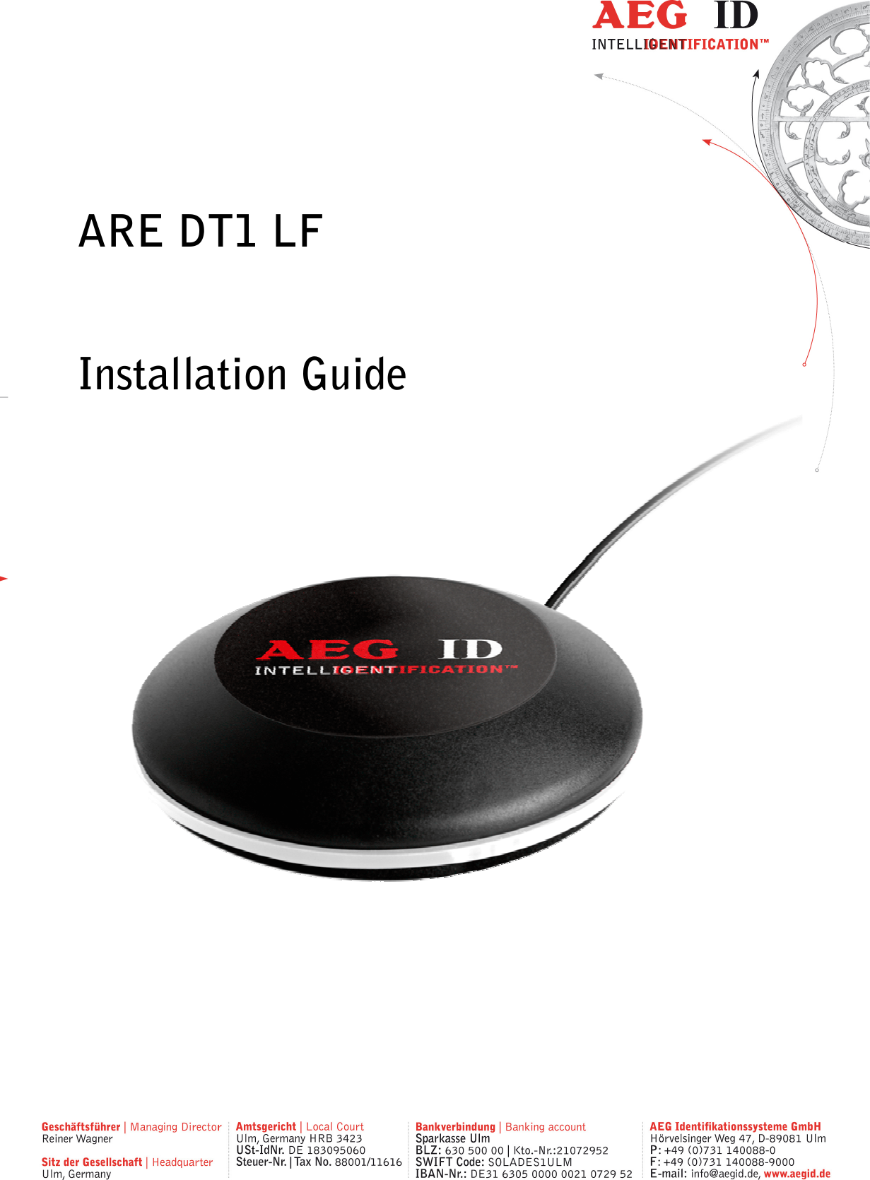
AEG Identifikationssysteme UDT100L RFID reader User Manual Installation Guide ARE DT1 LF 09 A17

AEG Identifikationssysteme GmbH RFID reader Installation Guide ARE DT1 LF 09 A17

User Manual

        ARE DT1 LF  Installation Guide
Rev 09                 --------------------------------------------------------------------------------2/27--------------------------------------------------------------------------------      1 INTRODUCTION ............................................................................................................ 4 2 STARTUP AND TESTING THE READER ...................................................................... 5 3 AEG ID INSTRUCTION SET .......................................................................................... 5 3.1 General ..................................................................................................................................................... 5 3.1.1 Entering instructions .......................................................................................................................... 6 3.1.2 Output format .................................................................................................................................... 6 3.1.2.1 Instruction specific output ........................................................................................................... 6 3.1.2.2 Output after changing a parameter .............................................................................................. 6 3.1.2.3 Output at parameter query ........................................................................................................... 7 3.1.3 Blank instuction ................................................................................................................................. 7 3.1.4 Incorrect instruction / error codes ....................................................................................................... 7 3.1.5 Upper and lower case ......................................................................................................................... 8 3.1.6 Linefeed ............................................................................................................................................. 8 3.2 Instructions for the hardware settings........................................................................................................ 9 3.2.1 BD – baudrate .................................................................................................................................... 9 3.2.2 EC – Echo .......................................................................................................................................... 9 3.2.3 LED – LED control .......................................................................................................................... 10 3.2.4 RST – reset ...................................................................................................................................... 10 3.2.5 HF – Antenna field ........................................................................................................................... 11 3.2.6 HID – human interface device/keyboard ............................................................................................ 12 3.2.7 KL – keyboard language ................................................................................................................... 13 3.2.8 VER – version .................................................................................................................................. 13 3.3 Instructions for reading settings .............................................................................................................. 14 3.3.1 CID – suppression of ID Codes .......................................................................................................... 14 3.3.2 CN – suppression of No Reads .......................................................................................................... 15 3.3.3 NID – Failure Protection .................................................................................................................. 16 3.3.4 INIT – initialization ......................................................................................................................... 16 3.3.5 LAA – LED automatic activity .......................................................................................................... 17 3.3.6 TSC – time show code ...................................................................................................................... 17 3.3.7 TOR – maximum reading time .......................................................................................................... 18 3.3.8 VSAVE – variables save ................................................................................................................... 18 3.3.9 VS – variables show ......................................................................................................................... 19 3.3.10 SA – algorithm selection................................................................................................................... 19 3.4 General reading instructions .................................................................................................................... 20 3.4.1 GT – get tag ..................................................................................................................................... 20 3.4.2 MD – mode of operation ................................................................................................................... 20 3.4.3 Basic data exchange process ............................................................................................................. 20 3.4.4 RD – read page ................................................................................................................................ 21 3.4.5 WD – write page .............................................................................................................................. 22 4 OPERATING MODES OF THE READER ...................................................................... 23
Rev 09                 --------------------------------------------------------------------------------3/27--------------------------------------------------------------------------------  4.1 MD 2 - triggered by an software command .............................................................................................. 23 4.2 MD 0 - continuous reading ...................................................................................................................... 24 5 INSTRUCTIONS .......................................................................................................... 25 6 FCC INFORMATION .................................................................................................... 26 7 HOTLINE ..................................................................................................................... 27 8 REVISIONS ................................................................................................................. 27
Rev 09                 --------------------------------------------------------------------------------4/27--------------------------------------------------------------------------------  1 Introduction This document describes the RFID-reading device ARE DT1 LF and the set-up procedure. The main features of the reader are listed below: • integrated USB interface selectable either communications port (similar RS232) or HID • USB powered (no external supply voltage necessary)  • compact design
Rev 09                 --------------------------------------------------------------------------------5/27--------------------------------------------------------------------------------  2 Startup and testing the reader • Connect the reader with the USB interface from your notebook or pc  • The reader is supplied via the USB interface. The supply differs depending on the used port. To reach the maximal reading distance a powerfull supply is essential. A USB hub with its own power supply can deliver this. • In the device manager there will appear a new device (AEG ID Communications Port) • In the brackets you see the port number of the device (e.g. COM5) • Open the “Demo Terminal“ on the CD • Open the menu “Settings” • You have to set the following settings: baud rate 19200 baud, 8 data bits, no parity, 1 stop bit, , no flow control. • Send the command „VER <CR>“ to the reader. The reader answers with the actual firmware version (e.g. AEG ID Multi-ISO V2.034). • Send the command “MD <SP> 0 <CR>” to the reader. The reader sends No Read messages (XXXXXXXX), while there is no transponder in the antenna field available (if CN parameter ist 0). If there is a transponder present in the antenna field the reader sends its serial.  3 AEG ID instruction set 3.1 General The command set described below defines the transfer of data on the serial interface. The commands consist of a command code and optionally of a parameter value. Commands are ter-minated by the control character <CR> (0Dh). The control character serves as command line termi-nator. Command codes and parameters,including all letters and numerical values, are principally transmit-ted as a sequence of ASCII characters (the value 255 (decimal) consequently as 32H, 35H, 35H; the command RST as 52H, 53H, 54H).
Rev 09                 --------------------------------------------------------------------------------6/27--------------------------------------------------------------------------------  3.1.1 Entering instructions The protocol format is as follows Command <SP> parameter <CR>  The space character <SP> separates commands from parameters and the <CR> character acts as command line terminator. For commands without parameter values (e.g. GT ) the <SP> character and parameter values are omitted. The command line is as short as this: Command <CR>  3.1.2 Output format Generally, every input terminated by <CR> is acknowledged by the reader. The following response protocols are different: 3.1.2.1 Instruction specific output After entering a valid command without a parameter value, the system answers by sending the param-eter value and <CR>. Example: Command:  GT <CR> Output: Transponder number or No Read <CR> 3.1.2.2 Output after changing a parameter After entering a valid command together with a parameter value, the system answers by sending the parameter value and <CR>. Example: Command:  MD <SP> 2 <CR> Output:   2 <CR>  After entering an invalid parameter value, the system answers with the corresponding error code. Error message: Command:  MD <SP> 4 <CR> Output:  NAK <SP> #02 <CR>
Rev 09                 --------------------------------------------------------------------------------7/27--------------------------------------------------------------------------------   3.1.2.3 Output at parameter query Parameter settings can be queried by sending the command without adding a parameter value. Exam-ple:  Command:  MD <CR> Output:   2 <CR>  3.1.3 Blank instuction If a single <CR> is input, the reader answers with a single <CR>. Example:  Command:  <CR> Output:   <CR>  3.1.4 Incorrect instruction / error codes If a command is not entered correctly, the reader sends one of the following error codes: ERROR CODE  MEANING NAK #00 <CR>  unknown command NAK #02 <CR>  wrong parameter NAK #10 <CR>  antenna failure XXXXXXXX <CR>  no read ACK  no error/acknowledge
Rev 09                 --------------------------------------------------------------------------------8/27--------------------------------------------------------------------------------  3.1.5 Upper and lower case The instruction set isn’t case-sensitiv. 3.1.6 Linefeed The reader does never send a linefeed. If you use a terminal program it can add the linefeed. You have to choose the option “displace CR with CR LF”.
Rev 09                 --------------------------------------------------------------------------------9/27--------------------------------------------------------------------------------  3.2 Instructions for the hardware settings 3.2.1 BD – baudrate The command BD enables the change of the baud rate. The settings are directly effective. Input format:  BD <SP> parameter <CR> Output (example):  2 <CR> Parameter:     3.2.2 EC – Echo The EC command allows to change the echo function.  Input format:  EC <SP> parameter <CR> Parameter: PARAMETER  FUNCTION 0  Echo off 1  Echo on  Output (example):  0 <CR> PARAMETER  FUNCTION 0  4800 baud 1  9600 baud 2  19200 baud 3  38400 baud
Rev 09                 --------------------------------------------------------------------------------10/27--------------------------------------------------------------------------------   3.2.3 LED – LED control With the command LED you can control the LED ring of the ARE DT1.  Input format:  LED <SP> parameter <CR> Output (example):  1 <CR> Parameter: PARAMETER  FUNCTION 0  off 1  on 2  Buzzer beeps, LEDs flash final state =initial state 3.2.4 RST – reset With the command RST the reader does a warmstart and loads the saved settings from the internal EEPROM. The antenna field is off after the reset. Input format:  RST <CR> Output (example):  ACK <CR>
Rev 09                 --------------------------------------------------------------------------------11/27--------------------------------------------------------------------------------   3.2.5 HF – Antenna field With the command HF, the antenna field can be set or reset manually.  Input format:  HF <SP> parameter <CR> Parameter: PARAMETER  FUNCTION 0  Switch off antenna field (this stops automatic mode) 1  Switch on antenna field (this stops automatic mode) 2  Automaticmode, the antenne field is activated by reader to comunicate with the transponder, afterwards it is switched off automatically. Therefore it is not compatible with the pass-word mode. The reader answers with the adopted antenna mode. Input (examplel):  HF <SP> 2 <CR> Output:  2 <CR>
Rev 09                 --------------------------------------------------------------------------------12/27--------------------------------------------------------------------------------   3.2.6 HID – human interface device/keyboard The command switches the interface ether to HID or RS232 emulation. Input format:  HID <SP> parameter <CR> Output (example):  0 <CR> Parameter: PARAMETER  FUNCTION 0  RS232 emulation, COM port 1  HID interface, keyboard  You have to unplug the device and plug the device in again to use the new setting. Don’t forget to use the command VSAVE to save the new setting. If the reader is in HID mode, you can not send any commands to the device. Because of that you have to use the Set-Up card – interface to switch the reader back from HID mode to serial interface mode. 1. Plug out the reader 2. Place card no reader 3. Plug in reader into USB-port 4. Wait for the beep tone from reader 5. Plug out reader 6. Remove card from reader 7. Plug in reader into USB port 8. Reader starts using the serial interface The Set-Up card – interfeace is a EM4305 transponder with data content 0x31D6B82E on page 3, 0x0006008F on page 4 and the password 0x25F8AB6D.
Rev 09                 --------------------------------------------------------------------------------13/27--------------------------------------------------------------------------------   3.2.7 KL – keyboard language With the command KL you can configure the language of the keyboard in HID mode. Input format:  KL <SP> parameter <CR> Output (example):  07 <CR> Parameter:  PARAMETER  FUNCTION 07  german 09  englisch 0A  spanish 0C  french 10  italien 13  dutch 16  portuguese 4B  canadian  3.2.8 VER – version With the command VER the reader sends the actual firmware version. Input format:  VER <CR> Output (example):  AEG ID V1.22 <CR>
Rev 09                 --------------------------------------------------------------------------------14/27--------------------------------------------------------------------------------  3.3 Instructions for reading settings 3.3.1 CID – suppression of ID Codes In the MD0 mode with CID=1 only the first of in succession identical transponder numbers is output on the serial interface. The possibly following identical transponder numbers are suppressed, as long as no new valid transponder number is received, processed and output. The get tag command is not influenced by this command. NoReads do not influence the data filtering. The leds are not influenced by this command. Input format:  CID <SP> parameter <CR> Output (example):  0 <CR> Parameter: PARAMETER  FUNCTION 0  No suppression 1  Suppression of equal transponder numbers  Example: A, B, C are different transponder codes, N is NoRead error code:    Sequence of reading cycles  Output sequence after filtering with CN=0 und CID=1 Output sequence after filtering with CN=1 und CID=1 N, N, ......,N, A, A, A, ....A, N,N, ......... N, N, ......,N, A, N, N, ....... A N. N, N, A, A, A, N, A, A, B, A, C, C, C, ....... N. N, N, A, N, B, A, C, ..... A, B, A, C  The settings are directly effective. Note:  The internal reference number is deleted in the following conditions:  • after a cold start
Rev 09                 --------------------------------------------------------------------------------15/27--------------------------------------------------------------------------------  • after a warm start (command line RST <CR>) • after entering the command line CID <SP> 1 <CR> This causes that the next transponder code is output definitely. Note: The filter function CID picks up the results of the complete reading cycles, while the parameter NID proceeds from the results of single readings! The filter function CID has effect on the serial in-terface only.  3.3.2 CN – suppression of No Reads Through  the  setting  CN=1  the  NoRead  results  after  a  get  tag  command  or  in  MD0  mode  are  sup-pressed on the serial interface. The leds are not influenced by this command. Input format:  CN <SP> parameter <CR> Output (example):  0 <CR> Parameter:    PARAMETER  FUNCTION 0  No suppression 1  Suppression of equal transponder numbers
Rev 09                 --------------------------------------------------------------------------------16/27--------------------------------------------------------------------------------   3.3.3 NID – Failure Protection NID specifies the number of identical transponder numbers, which have to appear for the result “suc-cessful reading“ within a reading cycle. In the setting NID = 1, two successive readings have to show the same transponder number.  Input format:  NID <SP> parameter <CR> Parameter: PARAMETER  FUNCTION 0  One out of one 1  Two out of two  Output (example):  1 <CR>  Sequence of readings  Lenght of the read-ing cycle Result of the read-ing cycle NoRead  1 reading  NoRead 0000125ED1, 0000125ED1  2 readings  0000125ED1 0000125ED1, 0000126ED1  2 readings  NoRead  3.3.4 INIT – initialization With the command INIT all paramters of this command set are set to the default values. After that you can save the settings with the command VSAVE.  Input format:  INIT <CR> Output (example):  ACK <CR>
Rev 09                 --------------------------------------------------------------------------------17/27--------------------------------------------------------------------------------   3.3.5 LAA – LED automatic activity The leds can be controlled by the reader or over the interface. You can set it up with the command LAA. If the reading settings CN=1, CID=1, CE=1 (when SI=0), MD=0 and LAA=0 are set, the reader beeps and flashes after successful reading. This setting makes sense when reader is used with HID setting. Input format:  LAA <SP> parameter <CR> Output (example):  0 <CR> Parameter: PARAMETER  FUNCTION 0  controlled by reader 1  manual controlling    Note:  If automatic LED control is active (LAA = 1), it delays processing   the following command until switching the LED is over. If several   reading or writing accesses to the transponder are planed, switch this   function off (LAA = 0).  3.3.6 TSC – time show code With the command TSC you can define the time in ms, after that the transpondercode is shown again, when the CID parameter is set to 1. If TSC is 00, the code is not shown a second time.  Input format:  TSC <SP> parameter <CR> Input format (example):  TSC <SP> 30 <CR> Output (example):  30 <CR>  => 30 * 100ms = 3000ms = 3 seconds   PARAMETER  FUNCTION 00  TSC is not active 01..FF  TSC time - in 100ms steps
Rev 09                 --------------------------------------------------------------------------------18/27--------------------------------------------------------------------------------   3.3.7 TOR – maximum reading time TOR is the timeout time for the reader. TOR is used in operation mode 2 as maximum gating time for a reading process. The length of the maximum gating time results from the equation gating_time = TOR * TB. The time constant TB (time base) has always the default value 100ms.  Input format:  TOR <SP> parameter <CR> Output (example):  05 <CR> Parameter:     3.3.8 VSAVE – variables save With the command VSAVE the following parameters are saved to the internal EEPROM: ACT, AFI2, AM, BD, CE1, CID, CN, KM1, KT1, LAA, MD, SI, TL1, TOR  Input format:  VSAVE <CR> Output (example):  ACK <CR> 1 just available in the ISO 14443A standard 2 just available in the ISO 15693 standard   PARAMETER  FUNCTION 00h  limits the reading process duration of exactly one reading cycle 01h..FFh  limits the reading process duration to maximum 1..256 times TB
Rev 09                 --------------------------------------------------------------------------------19/27--------------------------------------------------------------------------------  3.3.9 VS – variables show With the command VS the reader shows the settings of the following parameters: BD, CID, CN, EC, MD, NID, TOR  Input format:  VS <CR> Output (example):  BD <SP> 0 <SP>   …  3.3.10 SA – algorithm selection With the command SA the algorithm can be selected. Depending on the algorithm, the reader adapts its communication to the transponder suitable for the chip type respectively data format that shall be used. With parameter 0 ~ algorithm 14 ~ EM4305, EM4569 transponders additional commands to read and write selective (RD, WD) are available. With parameter 1 ~ algorithm 5 ~ ISO FDX format there are specific commands as well. This algorithm specific commands are listed in the “Addon_A..” documents. Input format:  SA<SP>parameter<CR> Output (example):  1<CR> Parameter: PARAMETER  FUNCTION (CHIP, FORMAT) 0  A14 ~ EM4305, EM4569 1  A5 ~ ISO FDX
Rev 09                 --------------------------------------------------------------------------------20/27--------------------------------------------------------------------------------  3.4 General reading instructions 3.4.1 GT – get tag The instruction GT executes one reading and sends back the transponder code of a transponder or the No Read error code (e.g. „FFFFFFFFFF“ oder „XXXXXXXXXX“).  Input format:    GT <CR>  Output (example):  0420212E5F <CR> 3.4.2 MD – mode of operation There a two modes of operation available. It is possible, that the reader reads constantly or triggered by an instruction. Input format:    MD <SP> parameter <CR> Output (example):  2 <CR> Parameter: PARAMETER  FUNCTION 0  constant reading mode 2  single reading mode  3.4.3 Basic data exchange process The master has to send an software command to start an read or write process of the reader. After doing all the necessary work at the readers site, the result of the reading or writing process or an failure code is sent back to the master. If there is used an read/write transponder, only the serial number of the transponder will be read if the basic read command „Get Tag“ („GT <CR>“) is applied. The data exchange of the whole memory can only be done, if the reader is set to the Mode 2 ( „selective Read (RD) “ and „write (WD)“).
Rev 09                 --------------------------------------------------------------------------------21/27--------------------------------------------------------------------------------  3.4.4 RD – read page • Start the reader with the command RD plus parameters (plus <CR>). You can read out just one block (with one parameter) or several blocks (with two parameters, first and last block number). • Wait for the answer • Analyse the received answer: 8 characters plus <CR>. Allowed characters  0 to F. The NoRead code is set to ( „XXXXXXXX“). The result of the reading process may also be seen at the LED’s. • LED L2 lit, if there was a successful read. • LED L3 lit, if there was a No Read.  Example:  RD <SP> 20 <CR>    read block 20 RD <SP> 16 <SP> 33 <CR> read all blocks from 16 to 33 Allowed values (block numbers of the transponder IC): ALGO 9 (1 kBit; P4150, P4450, P4550)    3 ... 33 ALGO 6 (2 kBit; Hitag 1)        16 ... 63 ALGO 14 (2, 4; kBitEM4305, EM4569)    5 … 15
Rev 09                 --------------------------------------------------------------------------------22/27--------------------------------------------------------------------------------   3.4.5 WD – write page The memory of the transponder is organised in blocks, containing 32 bits. The data’s of every single block must be changed separately. • Start the reader with the command WD plus parameters ( plus <CR>). The sent parameter consists of the block address and writing data’s (8 ASCII characters). • Wait for the answer • Analyse the received answer:  3 characters plus <CR>. ACK <CR>    Writing process was successful NAK <CR>    Writing process was not successful. NOT <CR>    The response of the transponder was not readable.  The result of the writing process may also seen at the LED’s. • LED L2 lit, if there was a successful write • LED L3 lit, if there was no successful write.  Example:  WD <SP> 20 <SP> < 0 1 2 7 A C D F > <CR>   write to block 20  Allowed values (block numbers of the transponder IC): ALGO 9 (1 kBit; P4150, P4450, P4550)    3 ... 33 ALGO 6 (2 kBit; Hitag 1)        16 ... 63 ALGO 14 (2, 4; kBitEM4305, EM4569)    5 … 15
Rev 09                 --------------------------------------------------------------------------------23/27--------------------------------------------------------------------------------  4 Operating modes of the reader In the AEG instruction set there are two operational modes defined: • MD 0 - continuous mode • MD 2 - the reading process is triggered by the serial interface In the next capters can you find a detailed functional description. The default mode is MD 2. 4.1 MD 2 - triggered by an software command The master sends the command to read a transponder code. The reader answers with the code or an error code. You can execute specific commands “Read” (RD) and “Write” (WD) just in mode MD2. In operating mode 2, the exciter is always turned off. Triggered by the software command (GT; RD; WD), the exciter is activated. After successful reading or writing of a transponder number the exciter is turned off automatically. Figure 9: Software triggered reading operation If the first reading cycle yields no result (NoRead), the on-time of the exciter is limited by the param-eter TOR (time out reader): Reading cycles are continuously started until either a transponder is read successfully or the time span corresponding to the value of the parameter TOR has expired. The read-er  will  not  interrupt  the  last  running  readout  cycle.  If  no  transponder  number  has  been  read,  a NoRead is output.  exciterprocessorinterfacereading cycle IDGT
Rev 09                 --------------------------------------------------------------------------------24/27--------------------------------------------------------------------------------   Figure 10: Software triggered reading operation with TOR>0  Please note: The TOR parameter is only active, if the  GT-Command is applied. Within the time span defined by the value of TOR no NoRead will be output on the interface!  4.2 MD 0 - continuous reading When operating continuously the exciter is switched on permanently. The reading cycles are initiated periodically. After an accomplished reading cycle the reading information is evaluated. After that data (either tran-sponder number or NoRead code) is output to the serial interface   Figure 11: continuous operation  exciterprocessorinterfaceTORGTreading processNoReadreading cycle  reading cycle  reading cycle exciterprocessorinterfacereading cycle ID ID IDreading cycle  reading cycle
Rev 09                 --------------------------------------------------------------------------------25/27--------------------------------------------------------------------------------  5 Instructions  To avoid any reduction of the reading distance of the reader, the reader must not be brought next to a metal surface (e.g. don’t put metallic sticker to the reader). This could lead to a significant change of the properties of the antenna circuit, which in turn reduces the reading range considerably or causes reading holes!  To get reliable readings, the distance between reader and transponder must be within the specified read-ing volume.  The reading characteristic in front of the reader is not isotropic. It depends also strongly on the orienta-tion between Reader and Transponder. To get the maximum reading distance, the orientation between reader and transponder must be well suited. To get a reliable readings or writings, the time of transponder while crossing the sensitive area of the antenna must be coordinated to the data transfer characteristics of transponder  In general the time depends on the speed of the transponder, the size of the transponder and the way the transponder is mounted on the vehicle and must be verified by field tests. Environmental electromagnetic noise may also reduce the read and write range considerably. Arrangement to eliminate such troubles must be done specific to the application by the help of engineers of the manufacturer.
Rev 09                 --------------------------------------------------------------------------------26/27--------------------------------------------------------------------------------  6 FCC Information    Federal Communications Commissions (FCC) Statement 15.21 You are cautioned that changes or modifications not expressly approved by the part responsible for com-pliance could void the user’s authority to operate the equipment. 15.105(b) This equipment has been tested and found to comply with the limits for a Class B digital device, pursuant to part 15 of the FCC rules. These limits are designed to provide reasonable protection against harmful interference in a residential installation. This equipment generates, uses and can radiate radio frequency energy and, if not installed and used in accordance with the instructions, may cause harmful interference to radio communications. However, there is no guarantee that interference will not occur in a particular installation. If this equipment does cause harmful interference to radio or television reception, which can be determined by turning the equipment off and on, the user is encouraged to try to correct the interfer-ence by one or more of the following measures: - Reorient or relocate the receiving antenna. - Increase the separation between the equipment and receiver. - Connect the equipment into an outlet on a circuit different from that to which the receiver is connect-ed. - Consult the dealer or an experienced radio/TV technician for help.
Rev 09                 --------------------------------------------------------------------------------27/27--------------------------------------------------------------------------------   7 Hotline If there are questions or suggestions please call the hotline:  Sales und Marketing:   +49 (0)731-140088-0 Fax:  +49 (0)731-140088-9000 e-mail: sales@aegid.de http://www.aegid.de 8 Revisions 11.01.13  Revision 00:    initial edition 30.01.13  Revision 01:    chapter 3.3.9 „TSC time show code“ added           chapter 3.6.9 „SF set flag“ added 21.01.13  Revision 02:     adapt to LF 20.11.13  Revision 03:    ALGO command 10.06.14  Revision 04 A17:  SA, NID command 18.09.14  Revision 05 A17:  USB power supply          (MK)  19.01.15  Revision 06 A17:  LAA, note, command delay        (MK) 18.05.16  Revision 07 A17:  FCC Information          (MK) 03.06.16  Revision 08 A17:  TSC command description corrections     (HL)  17.06.16  Revision 09 A17:  FCC Information correction        (MK)

Navigation menu