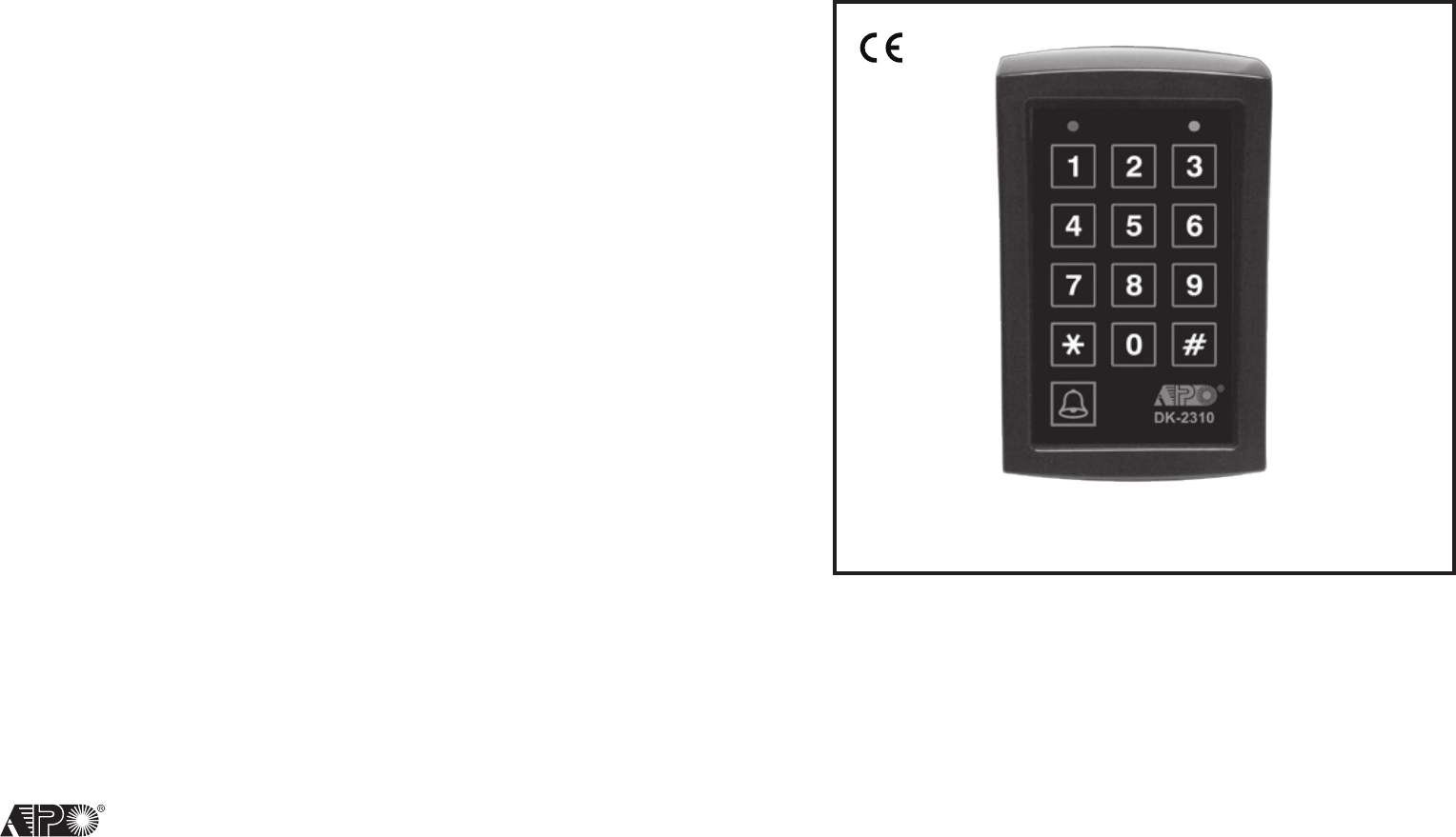
AEI Protect On Systems DK2310 Wireless Digital Keypad User Manual
AEI Protect-On Systems Limited Wireless Digital Keypad
user manual
VERSION: 05/2012
AEI
PROTECT-ON
SYSTEMS
LIMITED
www.apo-hk.com
WIRELESS DIGITAL
ACCESS CONTROL KEYPAD
DK-2310
Operating Instructions
FOR ELECTRIC LOCK AND SECURITY SYSTEM
RoHS
Compliance

TABLE OF CONTENTS
INTRODUCTION
SPECIFICATIONS
INSTALLATION
The Ciruit Board
Power Up The Keypad
Learn The Keypad ID
Delete A Keypad Or A Keyfob
Operation
The Pacier Tones & The LED Singals
The Loudness Of The Pacier Tone
SET SYSTEM IN PROGRAMMING MODE OR REFRESH THE SYSTEM
Set System Into Programming Mode With Master Code
Direct Access To Programming Mode With The "DAP" Code -- 8080
Refresh The System With The "Default Code" -- 9999
The Default Values Of The Keypad
FEATURE PROGRAMMING
Record A Master Code
Record The User Code For Output 1, 2 And 3
Record A Super User Code
Operaton And Function Of The Super User Code
Visitor Codes ( For Output 1 Only)
Personal Safety And System Lock-Out
User Code Entry Mode -- Auto or Manual Mode
Pacier Tones ON-OFF Selection
Back-lit ON-OFF Selection
Close The Programming Mode
THE COMPATIBLE RECEIVERS
DA-2311 -- Access Control Receiver
AD-2322 -- Access Control Power Supply With Receiver
DA-2800 -- Split-Decoded Access Controller With Receiver
.....................................................................................3
.................................................................................3
....................................................................................4
.................................................................................5
............................................................................6
.............................................................................6
.....................................................................6
.......................................................................................7
.............................................................7
................................................................7
...............................8
.............................................8
..................................8
...............................................9
................................................................9
.......................................................................1 0
..........................................................................1 0
.....................................................1 0
.....................................................................1 1
.................................................1 1
...............................................................1 2
..........................................................1 2
...................................................1 3
................................................................1 3
......................................................................1 4
..................................................................1 4
..................................................................1 5
.............................................................1 5
...........................................1 5
........................................1 5
215
THE COMPATIBLE RECEIVERS
Three receivers from us are compatible with the DK-2310 wireless keypad. Their features are listed
briey for your reference.
DA-2311 -- Access Control Receiver
DA-2311 is a 4-channel economic receiver designed to work with the DK-2310 for wireless access
control purpose. The 4-chanel controls the master output relay, the two open collector auxiliary outputs
and a built-in door chime.
• 12-24VDC Operation
• N.C. & N.O. Relay Dry Contacts for Fail-safe or Fail-secure Electric Lock
• Adjustable Timer for Door Lock
• Wireless Controlled Door Chime
• Two Open Collector Output Channels for Auxiliary Controls
• Auxiliary Connection Terminals for Wired Egress Button And Door Bell Button
• Compatible with Wireless Keypad (DK-2310) and Keyfobs (DA-12)
AD-2322 -- Access Control Power Supply with Receiver
AD-2322 is an uninterrupted power pack. It has a 12VDC/3A and a 12VDC/0.5A regulated power
supply inside for powering the electric lock and the associated electronic device, such as keypad. It
is also built-in with a 2-channel receiver compatible with the DK-2310 to control the door lock and the
built-in door chime. A split-decoder compatible with our DK-2800 series keypads for split-decoded
operation is also incorporated in this equipment.
• 220-240VAC Operation
• Power The 12VDC Device, Mainly The Electric Lock in Access Control System
• Compatible with Fail-safe or Fail-secure Electric Lock
• Built-in Charger for a 12V/7.0Ah Back-up Battery
• Adjustable Timer for Door Lock
• Wireless Controlled Door Chime
• Auxiliary Connection Terminals for Wired Egress Button And Door Bell Button
• Compatible with Wireless Keypad (DK-2310) and Keyfobs (DA-12)
DA-2800 -- Split-decoded Access Controller with Receiver
DA-2800 is a split-decoder designed to work with the DK-2800 keypads for split-decoded operation.
It is also built-in with a 4-channel receiver compatible with the DK-2310. The 4-channel controls the
3 output relays and a built-in door chime providing full features in access control and other auxiliary
controls.
• 12-24VDC Operation
• N.C. & N.O. Relay Dry Contacts for Fail-safe or Fail-secure Electric Lock
• Adjustable Timer for Door Lock
• Wireless Controlled Door Chime
• Two Output Relays with N.C. & N.O. Dry Contacts for Auxiliary Controls
• Auxiliary Connection Terminals for Wired Egress Button And Door Bell Button
• Compatible with Wireless Keypad (DK-2310) and Keyfobs (DA-12)
3
14
INTRODUCTION
The DK-2310 is a 9V battery operated 433Mhz wireless keypad designed to work in conjunction
with the receiver for access control. The products from us with receiver include the DA-2311 self-
contained access controller, the AD-2322 controller power pack, and the DA-2800 split-decoded
access controller. It is also compatible with most of the 433Mhz receivers on the market. The keypad
has the exibility to be positioned anywhere within range of the receiver without the need for wires. Its
4 controlling channels send out the commands to control the outputs and actuate the door bell in the
receiver. It is low power consumption. A 9V alkaline battery gives battery life of 1 year approximately
with 10-30 operations daily.
Remark : Please see your receiver’s manual for the available output channel(s).
Please see page 15 for the feature brief of the compatible receivers DA-2311, AD2322 and
DA-2800.
SPECIFICATIONS
Operating Voltage : 9V Alkaline Battery
Operating Current : 10uA in Quiescent; 10mA in Transmitting
Operation Temperature : -20 C to +70 C
Environmental Humidity : 5-95% Relative Humidity Non-condensing
Working Environment : Indoor or Outdoor; IP-55, Weatherproof
Number of User Codes : 10 for Each Channel, Total 30 User Code for The 3 O/P Channels
Number of Visitor Codes : 10 Visitor Codes for Output 1
User Code Length : 4-8 Digits, Over 100 Million Combinations
Timing for Code Entry : 10 Seconds
Keypad ID Code : One of the 1 Million ID Codes; Pre-programmed
Operating Frequency : 433Mhz
Maximum Distance : 50 Meters Approximate in Open Space
Dimensions : 126.3(H) X 75.6(W) X 40(D)
Weight : 208g Net
Housing : ABS Plastic
Specications are subject to change for modication without notice
10 User Codes for output 1 (channel 1)
10 User Codes for output 2 (channel 2)
10 User Codes for output 3 (channel 3)
1 Door Bell Actuator (channel 4)
10 Visitor Codes for output 1
1 Super User Code for operating of all the 3 outputs and making inhibit authorization for output 1
1 Master Code for programming authorization
1 DAP Code 8080 for programming authorization without master code
BACK-LIT ON-OFF SELECTION ( Location 9 )
CLOSE THE PROGRAMMING MODE ( * * )
Always close programming mode with * * to set system back to normal Operation after programming.
VALIDATION
------------------------------------- System is back to normal operation mode
CODE FOR BACK-LIT MODE
Two codes are available for selection.
0 --- Back-lit OFF ( Default )
1 --- Back-lit ON
VALIDATION
#
0 or 1
FUNCTION MODESLOCATIONS
9
The keyboard lights up when a key is pressed, which is convenient for the owner at night. The
illumination is OFF automatically 10 seconds after the last key is pressed and the keypad is left
in rest.
The back-lit function will slightly shorten the battery life.
No back-lit at all. The keypad consumes less power and results in longer battery life.
4
INSTALLATION
DK-2310
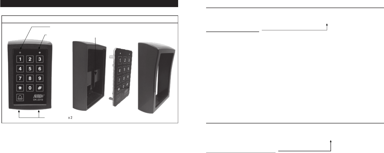
• Place the keypad outside that is convenient to reach but far from metal structure
• The location for the keypad must be within the receiving range of the receiver
• Open the box by loosing the screws of the xing frame with the supplied hex screw wrench. Take
the circuit module (xed on the faceplate) out carefully
• Fix the back box on wall with the screws supplied
• Snap the battery clip on the 9V alkaline battery and put it in the battery compartment
• Put the circuit module back to the box carefully. Push it in tightly and hold it to prevent drop-out.
• Put the xing frame back to the box. Make sure the rubber gasket is in the right position in the
frame for weatherproof shielding
• Secure the frame tightly on the box with the two screws at the bottom side. Fix them tightly with
the wrench.
Plastic Back Box
with Battery Case
Faceplate +
Circuit Module Fixing Frame
DER
REBMA
FIXING SCREWS
13
USER CODE ENTRY MODE - Auto or Manual Mode (Location 7)
USER CODE ENTRY MODES
Two entry modes are available for owner’s selection.
1 --- Auto Entry Mode -- (Default)
2 --- Manual Entry Mode
PACIFIER TONES ON-OFF SELECTION (Location 8)
PACIFIER TONES FUNCTION MODES
The Pacier Tone is the Beep Tones from the keypad, which include the tones of Successful Key entry (1
beep), Successful User Code entry (2 beeps) and the Unsuccessful User Code entry (5 beeps).
NOTE : The beeps for Power-up Delay do not belong to pacier tone and can not be OFF.
1 --- Pacier Tone Partially ON – (Default)
2 --- Pacier Tone ON
0 --- Pacier Tone OFF
The keypad checks the User Code automatically when the number of digits is reached. It is
not required to press of the # key to conrm. In auto entry mode, the User Codes MUST be
set in the same digit length of the Master Code. For example, if the Master Code is 4 digits,
then all User Codes are also 4 digits. Good for public access control.
Only the Pacifier Tones for Successful Code (2 beeps) and the Unsuccessful User Code
entry (5 beeps) are available. The key entry pacier tone is disabled for power saving.
All the Pacier Tones available from the keypad are enabled. This mode is only good for low
trafc entry/exit usage due to higher power consumption.
All the Pacier Tones are OFF. Good for power saving and silent environment.
Manual Entry Mode always requires the # key to follow the User Code for code checking.
The User Codes can be 4-8 digits and they are NOT required to set in the same digit length
with the Master Code. Manual Entry increases the level of security in code trial.
VALIDATION
#
1 or 2
ENTRY MODESLOCATIONS
7
VALIDATION
#
1 , 2 or 0
FUNCTION MODESLOCATIONS
8
5
12
VISITOR CODES (FOR OUTPUT 1 ONLY) (Locations 5)
The Visitor Codes are temporary codes for operating Output 1 only. They can be programmed as one
time codes or codes with valid time limit. The Visitor Codes will be cleared automatically after use if
they are one time codes, or, when the allowed time expires.
VISITOR ID
10 Visitor Codes can be programmed. They are represented by an
ID Number of 0 to 9.
VALID TIME
The time codes in this box MUST be two digits.
00 --- One Time Code
One Time Code has no time limit but it can only be used for ONCE.
It is cleared by the system automatically after use.
--- Time Limit in Hour(s)
The Visitor Code can be set with valid time limit of 1 Hour to 99 Hours with a
two digit time code of 01 to 99. The visitor code is cleared by the system when
the time limit reaches.
VISITOR CODES
The Visitor Codes can be 4-8 digits.
When a new Visitor Code is keyed in an ID box and conrmed, the old Visitor Code in that box is
erased
To delete a Visitor Code from its ID box --- 5
#
PERSONAL SAFETY AND SYSTEM LOCK-UP (Location 6)
LOCK-UP MODES
The Code Entry for the Lock-up Mode:
1
2
0
--- After 10 successive false User Code trials, the keypad locks during 30 seconds.
-- (Default)
--- After 10 successive false User Code trials, the keypad locks during 15 minutes.
Remark: Both of the above lock-ups can be released with the Super User Code at anytime.
Example : To release the lock-up
--- Disappearance of all the above lock-up securities.
4-8 DIGITS
5 #
VISITOR CODE VALIDATIONLOCATION VISITOR ID VALID PERIOD
VALIDATION
#
1 , 2 or 0
LOCK-OUT MODESLOCATIONS
6
SUPER USER CODE #
0 to 9
01 to 99
0 to 9
00 or
01 to 99
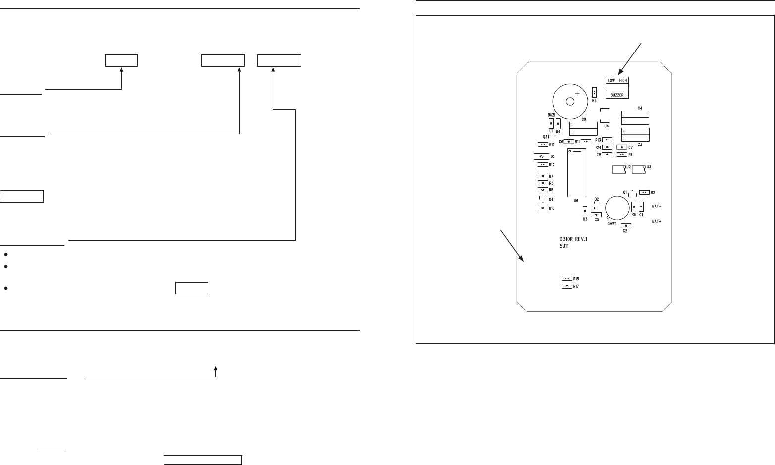
THE CIRCUIT BOARD
Selection of high or low beep
FCC ID: OGJ-DK2310
FCC ID Label & Location

611
RECORD A SUPER USER CODE ( Location 4)
The Super User Code is prepared for the owner to simply use it to operate the three outputs of the
system and to effect the prohibit function for Output 1.
SUPER USER CODE
The Super User Code has TWO functions. It can operate the three outputs or make inhibition to the
User Codes for the Output 1.
The Super User Code can be 4 to 8 digits.
When a new Super User Code is keyed in and conrmed, the old Super User Code is erased.
To delete the Super User Code from memory --- 4
#
OPERATION AND FUNCTIONS OF THE SUPER USER CODE
1) Operate Output 1, 2 and 3
The operation of the Super User Code is just like a normal User Code Plus a specific output
number.
---------- Output 1 Activates (Channel 1 Transmits)
---------- Output 2 Activates (Channel 2 Transmits)
---------- Output 3 Activates (Channel 3 Transmits)
2) Inhibit The User Codes For Output 1
The Super User Code can be used to inhibit the User Codes for the Output 1. It enhances the
security level of the access control system, such as stop the keypad after ofce hour or while the
house is nobody inside. Once the User Codes for Output 1 is inhibited, they become invalid. The
inhibit function is toggled in Start / Stop mode. The User Codes resume valid when the Super User
Code with the specic command number 9 is keyed-in again.
---------- All User Codes in Group 1 Disabled or Enabled in Toggle
NOTE: The above inhibition only applies to the User Codes and the Visitor Codes for output 1 but
does not affect the operation of Output 1, 2 and 3 with Super User Code.
4 to 8 Digits
MASTER CODE VALIDATIONLOCATION
4#
SUPER USER PIN
SUPER USER PIN
SUPER USER PIN
SUPER USER PIN
# 1
# 2
# 3
# 9
POWER UP THE KEYPAD
After snapping the 9V battery on the battery clip, the keypad is in the power up delay of one minute
and the keypad gives beep sound during the period. It goes to normal operation after the time expired.
The power up delay allows the keypad circuit to stabilize and it is also the only time for the keypad to
accept the DAP code for setting it into programming mode in case of the Master Code is forgotten.
See the programming option “Direct Access to Programming Mode with “DAP” Code – 8 0 8 0” for the
details.
Battery Low Indication :
The keypad checks the battery each time when it is used. The keypad will generate continuous
warning beeps for 10 seconds when low battery is detected. Replace with new battery immediately.
LEARN THE KEYPAD ID
It is necessary to register the keypad with the receiver prior to use. The receiver can be the DA-2311,
AD-2322, or the DA-2800 from our company.
DELETE A KEYPAD OR A KEYFOB
If a keypad or a keyfob is lost it is necessary to delete it from the receiver. Every time the receiver will
clear all the keypad & keyfob IDs from its memory. Re-learning of the existing keypads / keyfobs are
required.
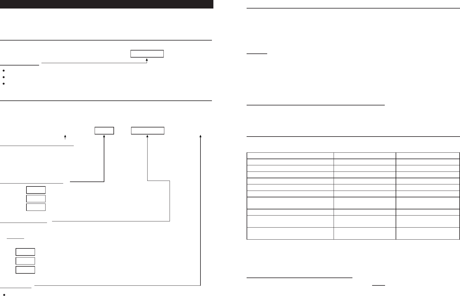
Press and hold the LEARN button on the receiver unit (It is equipped on the main circuit board
of the receiver) for 1 second until the STATUS LED turns ON.
The receiver is in a Waiting Period of 10 Seconds after the Status LED turning ON. It is waiting
for the keypad to send out its ID.
Press the BELL sign button on the keypad once within the waiting period. The keypad will send
out its ID immediately for the receiver to learn.
If your keypad already programmed with User Code(s), key in one of the user codes can also
achieve the learning of the keypad ID by the receiver.
The Status LED in the receiver turns OFF after the ID is learned.
Repeat the above learning procedures 1-4 for other keypads and/or remote keyfobs that are
used with the receiver. Total 40 keypads or keyfobs are allowed.
Press and hold the LEARN button for 8 seconds (The Status LED turns ON) until the LED gives
2 ashes to conrm that all the IDs are erased. After that, the LED turns OFF.
Record the new keypad and those not lost keyfobs again one by one with the procedures states
in the above section “Learn The Keypad ID”.
1)
2)
3)
4)
5)
1)
2)
7
10
FEATURE PROGRAMMING
After setting the system into programming mode, the feature values can be put into the system one by
one with the Programming Locations. Programming can be made continuously and it is not necessary
to be in order sequence. Just go to the desired location and key in the feature value.
RECORD A MASTER CODE ( Location 0 )
MASTER CODE
Master Code is the authorization code for setting the system into programming mode.
The master code can be 4 to 8 digits.
When a new master code is keyed in and conrmed, the old one is erased.
RECORD THE USER CODES FOR OUTPUT 1, 2 AND 3 ( Location 1, 2 & 3 )
10 User Codes are available for each output 1, 2 and 3 respectively. The User Codes MUST be unique
and not repeated. The owner can put one User Code at each Code ID box.
PROGRAMMING LOCATIONS
1 --- User Codes for Output 1
2 --- User Codes for Output 2
3 --- User Codes for Output 3
THE USER CODE ID BOX
a) Code IDs for storing the 10 User Codes to operate Output 1
b) Code IDs for storing the 10 User Codes to operate Output 2
c) Code IDs for storing the 10 User Codes to operate Output 3
THE USER CODES
Put one User Code of 4 to 8 digits in each User ID box.
Remark
To delete a NOT used User Code from its ID box :
1
# --- Deletion of an Output 1 User Code at ID box 0 to 9
2
# --- Deletion of an Output 2 User Code at ID box 0 to 9
3
# --- Deletion of an Output 3 User Code at ID box 0 to 9
VALIDATION
Press # to conrm an User Code is recorded. Two-beep conrms valid entry and the old User
Code is replaced.
4 to 8 Digits
MASTER CODE VALIDATIONLOCATION
0#
4 to 8 Digits
0 to 9
USER CODE VALIDATIONLOCATION CODE ID
1 - 3#
0 to 9
0 to 9
0 to 9
0 to 9
0 to 9
0 to 9
OPERATION
After the keypad and keyfob are registered in the receiver it can be used for door release in access
control or other controls with the auxiliary channels.
NOTE: Only the receiver incorporates with 3 channels can operate the auxiliary outputs with the
keypad or the kefob.
Keypad
Keyfob ( Optional -- if it is also learned by the receiver)
THE PACIFIER TONES & THE LED SIGNALS
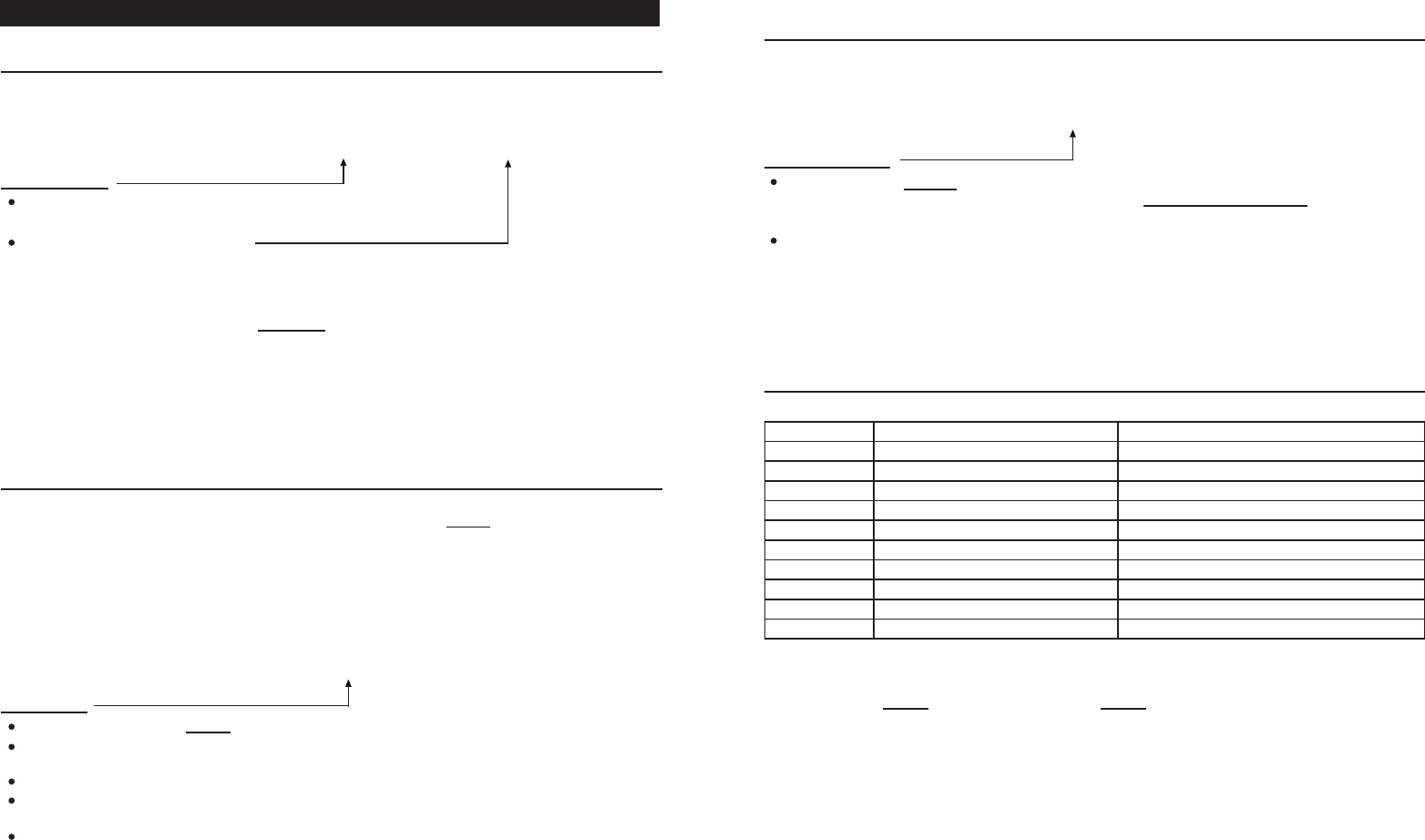
The buzzer and the amber LED indicator give following tones and signals respectively for system
status:
STATUS TONES * LED SIGNALS
1) On Programming Mode ----- 1 Flash / Sec (Amber LED)
2) Successful Key Entry 1 Beep -----
3) Successful Code in Programming 2 Beeps -----
4) Successful Code in Operation 2 Beeps 1 Flash (Amber LED)
5) Unsuccessful Code Entry 5 Beeps -----
6) Power Up Delay (1 Minute) Continuous Beeps -----
7) Output 1 Locked or Inhibited ----- 1 Flash / Sec During the
Wake-up Time (Red LED)
8) System Refreshing ----- Fast Flashes (Amber LED)
9) Code Already Existing in System 1 Long Beep (Refuse
Beep)
-----
10) Battery Low Warning Continuous Beeps for 10
Sec
-----
NOTE:
*
* *
* * *
THE LOUDNESS OF THE PACIFIER TONE
Two loudness levels can be set for the pacier tone with the BEEP jumper on the circuit board.
Key in one of the User Codes in Group 1 to operate the Output 1 of the receiver (door release).
Key in one of the User Codes in Group 2 to operate the Output 2 of the receiver (auxiliary O/P).
Key in one of the User Codes in Group 3 to operate the Output 3 of the receiver (auxiliary O/P).
Press the Bell Sign to operate the built-in door chime of the receiver.
Press button A, B or C to operate the Output 1, 2 or 3 of the receiver respectively
Press the button D to operate the built-in door chime of the receiver.
1)
2)
3)
4)
1)
2)
The Tones can be ON, Partially ON or OFF through the programming options at Location 8
The Amber LED – Status indication
The Red LED – Output 1 locked out or inhibited indication
Low -- Power Save Mode ( factory set )
High -- Louder Sound Mode -- ( higher sound level but will slightly shorten battery life )
i)
ii)
8
REFRESH THE SYSTEM WITH THE “DEFAULT CODE” --- 9 9 9 9
The system can be refreshed with the Default Code to clear all the old data.
DEFAULT CODE
The Default Code 9 9 9 9 is for setting the system back to default values. Once the default code is
entered and validated, all the old values will be cleared except the Master Code. Re-programming
of the features is necessary.
Make sure that you really want to clear the OLD values before entering the Default Code.
THE DEFAULT VALUES OF THE KEYPAD
PROGRAMMING
LOCATION PARAMETERS DEFAULT FUNCTIONS & VALUES
0 Master Code Not Affected *
1 User Codes for O/P 1 Nil ----- User Program Required
2 User Codes for O/P 2 Nil ----- User Program Required
3 User Codes for O/P 3 Nil ----- User Program Required
4 Super User Code Nil ----- User Program Required
5 Visitor Codes Nil ----- User Program Required
6 Personal Safety & Lock-out Code = 1, 10 False Code Lock-out 30 S
7 User Code Entry Mode Code = 1, Auto Entry Mode
8 Pacier Tones ON-OFF Selection Code = 1, Pacier Tone Partially ON
9 Back-lit ON-OFF Selection Code = 0, Back-lit OFF
NOTE:
i) The master code is NOT a default value. It is not affected in system refreshing.
ii) The DAP Code 8 0 8 0 and the Refreshing Code 9 9 9 9 are xed in the system program. It can not
be changed in any ways or be inuenced by the system in the default setting.
This device complies with Part 15 of the FCC Rules. Operation is subject to the following two conditions:
(1) This device may not cause harmful interference, and
(2) this device must accept any interference received, including interference that may cause undesired
operation.
FCC Caution: Any changes or modifications not expressly approved by the party responsible for
compliance could void the user's authority to operate this equipment.
9
DEFAULT CODE VALIDATION
9999 #
SET SYSTEM IN PROGRAMMING MODE OR REFRESH THE SYSTEM
SET SYSTEM INTO PROGRAMMING MODE WITH THE MASTER CODE
It is necessary to set the system into programming mode to accept the new programming values.
MASTER CODE
The Master Code can be a factory set master code or the private
master code set by the owner to replace the factory set master code.
Validate the master code with * *
NOTE:
a)
b)
DIRECT ACCESS TO PROGRAMMING MODE WITH THE “DAP” CODE – 8 0 8 0
In case of the Master Code is forgotten. The owner requires to apply the following procedures
precisely to set the system into programming mode with the DAP code 8 0 8 0.
1)
2)
DAP CODE
The DAP code is xed at 8 0 8 0 .
The system will go back to normal operation after the power up period expired.To set it back to
power-up mode, repeat procedures (1) & (2) are required.
Validate the DAP code with the * * .
2-beep conrms the system is in Programming Mode. The amber LED ashes. The OLD Master
Code is cleared.
See “RECORD A MASTER CODE” for the details of programming a new master code.
For the owner’s convenience in programming for the rst time, a Master Code “0 0 0 0” has been
put in the keypad before exiting factory. To compromise security, in all cases, the owner should
program a personal Master Code to invalidate the factory set master code.
2-beep confirms that the master code is valid and the amber LED flashes during keypad in
Programming Mode.
Switch OFF all the power for 1 minute to ensure that the system is fully discharged. Press any
button will shorten the discharging time.
Switch ON power again. The system will be in Power-up Mode for 1 minute and the buzzer starts
to give beeps during the period. This is the only time that the system allows entry of the DAP code.
0000
8080
MASTER CODE VALIDATION
DAP CODE VALIDATION