AFAR Communications 24010E Wireless Ethernet Bridge User Manual PulsAR Manual
AFAR Communications, Inc Wireless Ethernet Bridge PulsAR Manual
User Manual

pulsAR Wireless Ethernet Bridge
Operator’s Manual
Models: AR-9010E
AR-9027E
AR-24010E
AR-24027E
AR-24110E
February 2010
AFAR Communications Inc.
81 David Love Place
Santa Barbara, CA 93117
Tel: +1 805 681 1993
Fax: +1 805 681 1994
go the distance

pulsAR Wireless Ethernet Bridge
Operator’s Manual
Models: AR-9010E
AR-9027E
AR-24010E
AR24027E
AR24110E
February 2010
AFAR Communications Inc.
81 David Love Place
Santa Barbara, CA 93117
Tel: +1 805 681 1993
Fax: +1 805 681 1994
$25.00

pulsAR radio Operator’s Manual
- i -
Customer Service
AFAR provides customer service during normal U.S. Pacific Coast business hours and may be reached by
voice, fax, or email as follows:
Tel: +1 805 681 1993
Fax: +1 805 681 1994
email: support@afar.net
If you must return the equipment, please contact us for a Return Material Authorization (RMA) number.
Equipment should be shipped to:
AFAR Communications Inc.
81 David Love Place,
Santa Barbara, CA 93117
U.S.A.
pulsAR radio Operator’s Manual
- ii -
STATEMENT OF WARRANTY
Afar Communications Inc. products, except as otherwise stated in an applicable price list, are warranted against
defects in workmanship and material for a period of one (1) year from date of delivery as evidenced by Afar
Communications Inc.’s packing slip or other transportation receipt.
Afar Communications Inc.’s sole responsibility under this warranty shall be to either repair or replace, at its
option, any component which fails during the applicable warranty period because of a defect in workmanship
and material, provided purchaser has promptly reported same to Afar Communications Inc. in writing. All
replaced products or parts shall become Afar Communications Inc.’s property.
Afar Communications Inc. shall honor this warranty at its facility in Goleta, California. It is purchaser’s
responsibility to return, at its expense, the defective Product to Afar Communications Inc. Purchaser must
notify Afar Communications Inc. and obtain shipping instructions prior to returning any product. Afar
Communications Inc. will pay the transportation charges for the return of the Product to purchaser but not
including any custom clearance fees and other related charges which shall be paid by purchaser. If Afar
Communications Inc. determines that the Product is not defective within the terms of the warranty, purchaser
shall pay Afar Communications Inc. all costs of handling, transportation and repairs at the prevailing repair
rates.
All the above warranties are contingent upon proper use of the Product. These warranties will not apply (i) if
adjustment, repair, or parts replacement is required because of accident, unusual physical, electrical or
electromagnetic stress, negligence, misuse, failure of electric power environmental controls, transportation, or
abuses other than ordinary use (ii) if the Product has been modified or has been repaired or altered outside Afar
Communications Inc.’s factory, unless Afar Communications Inc. specifically authorizes such repairs or
alterations; (iii) where Afar Communications Inc. serial numbers, or quality assurance decals have been
removed or altered.
Afar Communications Inc. reserves the right to make product improvements without incurring any obligation or
liability to make the same changes in Products previously manufactured or purchased.
No person, including any dealer, agent or representative of Afar Communications Inc. is authorized to assume
for Afar Communications Inc. any other liability on its behalf except as set forth herein. Afar Communications
Inc. hereby disclaims all implied warranties of products including without limitation, all implied warranties of
merchantability or fitness for a particular purpose. The warranties expressly stated herein are the sole
obligation or liability on the part of Afar Communications Inc. arising out of or in connection with the sale or
performance of the products.
In no event will Afar Communications Inc. be liable to purchaser for (i) procurement costs; (ii) special,
indirect or consequential damages; (iii) any damages resulting from loss of use, data or profits arising out of the
use of Afar Communications Inc. products. In no event shall Afar Communications Inc. be liable for any
breach of warranty in an amount exceeding the net selling price of any defective Product.

pulsAR radio Operator’s Manual
- iii -
FCC Notice
This device complies with part 15 of the FCC Rules. Operation is subject to the
following two conditions: (1) This device may not cause harmful interference, and (2)
this device must accept any interference received, including interference that may
cause undesired operation.
This equipment has been tested and found to comply with the limits for a Class B digital
device, pursuant to Part 15 of the FCC Rules. These limits are designed to provide
reasonable protection against harmful interference in a residential installation. This
equipment generates, uses, and can radiate radio frequency energy and, if not installed and
used in accordance with the instructions, may cause harmful interference to radio
communications. However, there is no guarantee that interference will not occur in a
particular installation. If this equipment does cause harmful interference to radio or television
reception, which can be determined by turning the equipment off and on, the user is
encouraged to try to correct the interference by one or more of the following measures:
• Reorient or relocate the receiving antenna.
• Increase the separation between the equipment and receiver.
• Connect the equipment into an outlet on a circuit different from that to which the
receiver is connected.
• Consult the dealer or an experienced radio/TV technician for help.
Changes or modifications not expressly approved in writing by AFAR Communications Inc.
may void the user’s authority to operate this equipment. AFAR Communications Inc. can not
accept any financial or other responsibilities that may be the result of your use of this
information, including direct, indirect, special, or consequential damages. Refer to warranty
documents for product warranty coverage and specifics.
Industry of Canada Notice
These devices have been designed to operate with two antennas each, listed on page 3-6,
and having a maximum gain of 15 dBi at 900 MHz, or 24 dBi at 2.4 GHz. Antennas having a
gain greater than the values above are strictly prohibited for use with these devices. The
required antenna impedance is 50 ohms.
Operation is subject to the following two conditions: (1) this device may not cause
interference, and (2) this device must accept any interference, including interference that may
cause undesired operation of the device.
To reduce potential radio interference to other users, the antenna type and its gain should be
so chosen that the equivalent isotropically radiated power (e.i.r.p.) is not more than that
permitted for successful communication.
pulsAR radio Operator’s Manual
- iv -

pulsAR radio Operator’s Manual
- v -
TABLE OF CONTENTS
1 PRODUCT DESCRIPTION ........................................................................................ 1-1
1.1 RADIO OVERVIEW ............................................................................................................................... 1-1
1.2 RADIO COMPONENTS........................................................................................................................... 1-2
1.3 RADIO CONNECTORS ........................................................................................................................... 1-3
1.4 RADIO POWER ..................................................................................................................................... 1-5
1.5 OUTDOOR INTERCONNECT CABLE....................................................................................................... 1-7
2 NETWORK TOPOLOGIES AND APPLICATIONS ............................................... 2-1
2.1 NETWORK TOPOLOGIES....................................................................................................................... 2-1
2.1.1 Point to point .............................................................................................................................. 2-2
2.1.2 Point to Multipoint...................................................................................................................... 2-2
2.1.3 Tree topology.............................................................................................................................. 2-3
2.1.4 Linear Network........................................................................................................................... 2-4
2.2 ROAMING ............................................................................................................................................ 2-5
2.3 TIME DIVISION DUPLEX ...................................................................................................................... 2-6
2.3.1 Fixed and variable cycle split..................................................................................................... 2-6
2.3.2 On demand bandwidth allocation............................................................................................... 2-7
2.4 RADIO CO-LOCATION AND INTERFERENCE........................................................................................... 2-8
2.4.1 Radio co-location ....................................................................................................................... 2-8
2.4.2 Co-located radios self-interference ............................................................................................ 2-8
2.4.3 SPAN Network synchronization.................................................................................................. 2-9
2.4.4 Heartbeat suppression.............................................................................................................. 2-11
2.4.5 Synchronization with NetCrossing Gateways........................................................................... 2-12
2.5 ETHERNET BRIDGING ........................................................................................................................ 2-13
2.5.1 Self-learning bridging............................................................................................................... 2-13
2.5.2 Packet priorities ....................................................................................................................... 2-14
3 INSTALLATION AND SETUP................................................................................... 3-1
3.1 BENCH CHECK OUT............................................................................................................................. 3-1
3.1.1 Using the radio Ethernet connection .......................................................................................... 3-1
3.1.2 Using the radio auxiliary port .................................................................................................... 3-2
3.2 FIELD INSTALLATION .......................................................................................................................... 3-3
3.2.1 Mounting Bracket installation .................................................................................................... 3-3
3.2.2 Earth Grounding......................................................................................................................... 3-4
3.2.3 Power/Ethernet cable ................................................................................................................. 3-5
3.2.4 Antenna Installation ................................................................................................................... 3-6
3.2.5 Antenna Alignment ..................................................................................................................... 3-6
3.2.6 Radio Configuration................................................................................................................... 3-7
3.2.7 Spectrum Analysis and channel selection................................................................................... 3-8
3.2.8 Output Power Limits (FCC) ....................................................................................................... 3-9
3.2.9 Output Power Limits (CE).......................................................................................................... 3-9
3.2.10 Maximum Permissible Exposure (MPE) Limitations.................................................................. 3-9
3.3 UPGRADING THE FIRMWARE. ............................................................................................................ 3-10
3.3.1 Description ............................................................................................................................... 3-10
3.3.2 Installing new firmware through the Ethernet port .................................................................. 3-11
3.3.3 Installing new firmware using Telnet .......................................................................................3-13
3.3.4 Installing new firmware using the RS-232 serial port .............................................................. 3-14
3.3.5 Feature upgrades...................................................................................................................... 3-16
4 COMMANDS ................................................................................................................ 4-1
4.1 CONFIGURATION TECHNIQUES............................................................................................................. 4-1
4.2 COMMAND SYNTAX............................................................................................................................. 4-2
4.3 CONFIGURATION MANAGEMENT COMMANDS ..................................................................................... 4-3
4.4 MAJOR CONFIGURATION PARAMETERS............................................................................................... 4-6
pulsAR radio Operator’s Manual
- vi -
4.5 INTERNET PROTOCOL (IP) MANAGEMENT COMMANDS..................................................................... 4-11
4.6 INSTALLATION AND LINK MONITORING COMMANDS ........................................................................ 4-13
4.7 FILE UTILITIES................................................................................................................................... 4-18
4.8 EVENT LOGGING COMMANDS ........................................................................................................... 4-20
4.9 MISCELLANEOUS COMMANDS ........................................................................................................... 4-21
5 NETWORK MANAGEMENT .................................................................................... 5-1
5.1 TELNET................................................................................................................................................ 5-1
5.1.1 General ....................................................................................................................................... 5-1
5.1.2 Starting a Telnet Session............................................................................................................. 5-1
5.1.3 Telnet Security ............................................................................................................................ 5-2
5.2 SNMP ................................................................................................................................................. 5-2
5.2.1 Command Line Interface Versus SNMP ..................................................................................... 5-2
5.2.2 What is SNMP?........................................................................................................................... 5-3
5.2.3 Security Considerations in SNMP .............................................................................................. 5-3
5.2.4 Examples of Network Management Systems............................................................................... 5-4
5.2.5 PulsAR radio Management Information Base (MIB).................................................................. 5-4
5.3 UDP COMMAND AND DATA INTERFACE ............................................................................................. 5-5
5.3.1 Purpose....................................................................................................................................... 5-5
5.3.2 UDP Command Packet formats.................................................................................................. 5-5
6 RF LINK DESIGN ........................................................................................................ 6-1
6.1 ANTENNA SELECTION.......................................................................................................................... 6-1
6.1.1 Antenna Types............................................................................................................................. 6-1
6.1.2 Directionality.............................................................................................................................. 6-1
6.1.3 Gain ............................................................................................................................................ 6-2
6.1.4 Polarization ................................................................................................................................ 6-2
6.1.5 Antenna Orientation ................................................................................................................... 6-3
6.2 RF PATH ANALYSIS ............................................................................................................................ 6-3
6.2.1 Line-of-Sight Requirements ........................................................................................................ 6-3
6.2.2 Earth curvature........................................................................................................................... 6-5
6.2.3 Fresnel Zone ............................................................................................................................... 6-5
6.2.4 Atmospheric Refraction .............................................................................................................. 6-6
6.2.5 Clearing Obstructions................................................................................................................. 6-6
6.3 RF LINK BUDGET CALCULATIONS ...................................................................................................... 6-7
APPENDIX A – COMMAND SUMMARY ..................................................................... A-1
APPENDIX B – SPECIFICATIONS ................................................................................ B-1
APPENDIX C – CHANNEL FREQUENCIES ................................................................ C-1
APPENDIX D – ETHERNET CONSOLE PROGRAM ................................................. D-1
APPENDIX E – CABLE DIAGRAMS ............................................................................. E-1
APPENDIX F – QUICK SETUP EXAMPLES.................................................................F-1

pulsAR radio Operator’s Manual
1-1
1 PRODUCT DESCRIPTION
1.1 Radio Overview
The family of pulsAR Wireless Ethernet Bridges consist of license free radios that can be used to
bridge Ethernet LANs (Local Area Networks) across distances ranging from a few hundred feet to 50
miles (80 km) and beyond. You can deploy them in a variety of topologies from a simple point-to-
point link to a general mesh “tree” topology where any subscriber node can also be used as an access
point to nodes further downstream. For mobile applications you can configure subscriber nodes to
autonomously roam between multiple access points, keeping the mobile nodes connected to the
network at all times.
All radios use Direct Sequence Spread Spectrum and operate in the “Industrial Scientific and
Medical” (ISM) bands, either at 900 MHz or 2.4 GHz. Table 1 shows the main characteristics of the
5 models. Refer to appendix B for the complete specifications.
Table 1.1 pulsAR radio models
Model number: AR-9010E AR-9027E AR-24010E AR-24027E AR-240110E
Frequency Band (MHz) 902 to 928 902 to 928 2400 to 2483 2400 to 2483 2400 to 2483
Occupied Bandwidth (MHz) 1.7 4.6 1.7 4.6 17
Maximum data rate (Mbps) 1.1 2.75 1.1 2.75 11.0
The pulsAR radios are designed from the ground up to provide reliable wireless networks under
adverse conditions, often encountered in the unlicensed bands. This includes the following features:
1. All the electronics are housed in an environmentally sealed enclosure rated for outdoor
installation. You can mount the unit in close proximity to the antenna, which increases system
performance by avoiding RF cable losses or expensive rigid coax cables. The radio is powered over
the Ethernet cable.
2. Several models have an RF bandwidth that is much narrower than other unlicensed devices. This
has several advantages, namely (i) the radio sensitivity is greatly improved allowing longer ranges,
(ii) there is a much larger number of non-overlapping channels to choose from, and (iii) it is much
easier to find an unused gap in a crowded spectrum.
3. For long range links in a crowded spectrum the most desirable receive frequencies at each end of
the link are often different. In all pulsAR radios the transmit and receive frequencies can be selected
independently of each other.
4. The radio incorporates spectrum analysis and timing analysis tools, which allows you to quickly
perform a survey of the RF environment without the need for spectrum analyzers.
pulsAR radio Operator’s Manual
1-2
5. Unique antenna alignment aid provides audio feedback proportional to the RSSI, freeing the
installer’s hands to adjust and tighten the antenna without having to hold or look at other
instrumentation.
The radios implements a transparent bridge algorithm, where each unit automatically learns the
addresses of all stations in the network and forwards over RF only the traffic that needs to be
delivered to the remote units. In the mesh tree network where packets may need to go through
multiple hops, the radios always route the packets to reach their destination with the minimum
number of hops.
If the application requires a serial synchronous interface, the radios can be paired with the Afar
NetCrossing™ Gateway to provide both an Ethernet and a serial link of up to 2048 kbps across the
same wireless connection. In this case the NetCrossing™ Gateway provides both the power and data
to the radio across the single CAT5 cable. Refer to the NetCrossing™ Gateway Operator’s Manual
for complete details.
The pulsAR radios are the building block for the Afar “Synchronized PulsAR Network” (SPAN). In a
SPAN network all radios synchronize their transmissions such that all co-located radios transmit and
receive at the same time, thereby avoiding self-generated interference. This technique allows
deploying large networks with upwards of 24 radios co-located without generating self-interference.
Each pulsAR radio can be configured over a local serial interface or over the Ethernet using an
“Ethernet console” program provided by Afar. Once a unit is configured with an IP address you can
also configure and monitor the unit using Telnet or SNMP. The radio firmware, in non-volatile
memory, can also be updated remotely.
1.2 Radio Components
Table 1.1 below shows the part numbers of various accessories related with the pulsAR radio. You
may have received some of these accessories bundled with your radios.

pulsAR radio Operator’s Manual
1-3
Table 1.2 – pulsAR acccessories
Description Part No.
Bracket hardware for securing the pulsAR unit to an outdoor mast KIT-0601
Bracket hardware for securing the pulsAR unit to a flat surface KIT-0605
AC Power Inserter Module with 110-240 VAC power supply
with a 6 ft USA 3-prong power cord:
with a 6ft European connector (Schuko) power cord
PWI-0109-06A
PWI-0109-06B
DC Power Inserter Module with pigtail for external DC connection PWI-0106
CD with this Operator’s Manual, Econsole program, and other application notes.
Outdoor rated cat5 cable for connection between pulsAR radio and power inserter
module (xxx is the length is feet)
CBL-0503-xxx
Auxiliary port cable for RS-232 connection CBL-0403
Auxiliary port cable with Audio jack for antenna alignment CBL-0404
Lightning arrestor for the antenna ports SUR-0205
Surge suppressor for the Ethernet and Power CAT5 cable SUP-0202
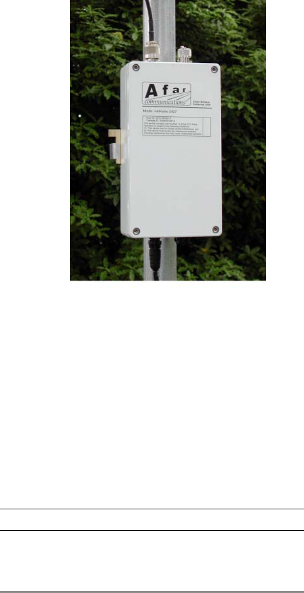
1.3 Radio Connectors
Figure 1.1 shows a pulsAR radio mounted on a mast. The radio is housed in a metal enclosure with
two N-female connectors at the top for connection to RF antennas, and two special purpose
connectors, at the bottom, for DC power, Ethernet data and control.
The function of each connector is described in the table below.
Table 1.3 – PulsAR Connectors
Connector Type Function
A N-Female RF connector to antenna A
B N-Female RF connector to antenna B (used in the tree topology)
C Lumberg
3 pin male
Auxiliary port (3 pin) used as an antenna alignment aid and for
RS-232 console port.
D Lumberg
8 pin male
10/100 Base-T data interface and DC power input (8 pin).
Must be connected to the “Power Inserter Unit” with a CAT 5
cable.
pulsAR radio Operator’s Manual
1-4
Figure 1.1. Pole Mounted Radio
An eight-conductor CAT 5 cable must be connected between the pulsAR radio and either a Power
Inserter Unit or an Ethernet port capable of providing Power over Ethernet (PoE) per IEEE 802.3af.
The wiring for this cable is shown in Figure 1.3.
Table 1.4 shows the pin assignment of the three pin auxiliary port connector. The unit is shipped with
a cover in this connector. The connector can be used during installation as a console port and also as
an audio antenna alignment aid. There are two optional cables to convert from this non-standard 3-
pin connector to either a DE-9 connector (for RS-232 console) or to a standard audio jack (for
connection to a headphone). See Appendix E for cable diagrams.
Table 1.4 – Auxiliary Port Connector Pin Assignments
Pin Signal Name Abbr. Direction
1 Receive Data RD Radio Output
2 Transmit Data TD Radio Input
3 Ground GND
pulsAR radio Operator’s Manual
1-5
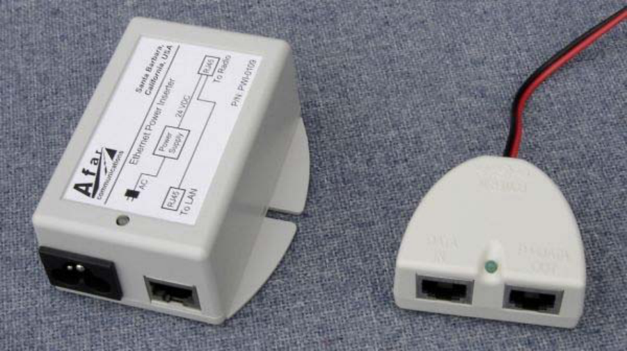
1.4 Radio Power
The pulsAR radio complies with the IEEE 802.3af Power over Ethernet (PoE) standard when power
is applied over the data line pairs (pins 1-2 and 3-6). You typically can connect the radio directly to a
PoE port of an Ethernet switch or router and it will provide power to the radio.
Alternatively the radio may also be powered over the spare cat5 line pairs (pins 4-5 and 7-8). On
these lines the radio accepts DC voltage over a very wide range (10 VDC to 58 VDC), allowing it to
easily be powered by a 12 V battery. This method is not in compliance with the IEEE 802.3af mode
B which restricts the voltage range to 48 VDC..
Afar provides two Power Inserter devices (figure 1.2) that use this second method. One is for
operation from an AC source (110-240 VAC), and the other for operation from a DC source (10 to 58
VDC).
The AC Power Inserter Unit includes a power supply for connection to an AC outlet (110-240 VAC),
two RJ45 connectors and a bi-color LED. The two RJ-45 connectors are labeled “To LAN” and “To
Radio”.
The DC Power Inserter Unit has two RJ45 connectors labeled “Data In”, “P+Data Out”, a green LED,
and a 10 ft pigtail cable for connection to your DC supply voltage or the DC/DC converter.
Figure 1.2 – AC and DC Power Inserter Units

pulsAR radio Operator’s Manual
1-6
Table 1.5 – Power Inserter Units
Connector/LED Type Function
To LAN
DATA IN
RJ-45 10/100 Base-T to be connected to the Local Area Network. You
can connect this directly to the LAN port of a computer or to an
Ethernet hub. The radio auto-detects and provides the cross-over
function when required. See table 1.5 for pin assignments.
To radio
P+DATA OUT
RJ-45 Carries the DC power and Ethernet signals to the radio. See table
1.6 for pin assignments.
LED
(AC Power Inserter)
Amber/
Green
Amber: Indicates that the power inserter unit has power from the
wall supply but no power is being drawn by the radio.
Green: Indicates that the radio is drawing power.
LED
(DC Power Inserter)
Green Indicates that there is DC power in the pigtail input
WARNING
The Power Inserter connectors labeled “To radio” or “P+DATA OUT” includes DC voltage in two of
the pins. It must not be connected to a LAN as this voltage may damage some LAN cards.
Table 1.6 – “To LAN” (DATA IN) Ethernet Connector Pin Assignments
Pin Signal Name Abbr. Direction
1 Ethernet Tx Tx (+) Radio to Ethernet(1)
2 Ethernet Tx Tx (-) Radio to Ethernet(1)
3 Ethernet Rx Rx (+) Ethernet to Radio(1)
4 (not connected)
5 (not connected)
6 Ethernet Rx Rx (-) Ethernet to radio(1)
7 (not connected)
8 (not connected)
(1) With auto-negotiation enabled the radio also provides an automatic cross-over function.

pulsAR radio Operator’s Manual
1-7
Table 1.7 – “To radio” (P+DATA OUT) Ethernet Connector Pin Assignments
Pin Signal Name Abbr. Direction
1 Ethernet Tx Tx (+) Radio to Ethernet
2 Ethernet Tx Tx (-) Radio to Ethernet
3 Ethernet Rx Rx (+) Ethernet to Radio
4 VDC DCV (+) Power Inserter to Radio
5 VDC DCV(+) Power Inserter to Radio
6 Ethernet Rx Rx (-) Ethernet to Radio
7 ground GND(-) Power Inserter to Radio
8 ground GND(-) Power Inserter to Radio
1.5 Outdoor Interconnect Cable
The interconnect cable between the Power Inserter Unit and the radio carries the following signals
1. DC voltage to supply power to the pulsAR radio.
2. 10/100 Base-T Ethernet data.
Both these signals are carried in a single CAT 5 cable. The system is designed to allow cable lengths
in excess of the 100 meters (300 feet) of the IEEE Ethernet specification. Figure 1.3 shows the
interconnect diagram for this cable and connector types. Table 1.8 lists a few part numbers and
sources of appropriate CAT 5 cable for this application. AFAR Communications Inc. carries several
pre-made cables of different lengths. See Appendix E for connector diagrams, part numbers, and
assembly instructions.
Figure 1.3 - CAT 5 Outdoor Interconnect cable diagram
RADIO_ETH_TX+
RADIO_ETH_TX-
RADIO_ETH_RX+
VDC
VDC
RADIO_ETH_RX-
GND
GND
1
7
2
3
5
4
8
6
1
2
3
4
5
6
7
8
RJ 45
Radio “D” Port
(Lumberg Connector)

pulsAR radio Operator’s Manual
1-8
Table 1.8 – Indoor/Outdoor Unit CAT 5 cable
Part number Manufacturer Description
7919A Belden Shielded outdoor rated cable
18-241-31(gray)
18-241-11 (beige)
Superior Essex Unshielded outdoor rated cable
5EXH04P24-BK-R-
CMS-PV
CommScope Unshielded outdoor rated cable
2137113 (ivory)
2137114 (gray)
General Cable Unshielded outdoor rated cable
BC1002 Belden Unshielded outdoor rated cable

pulsAR radio Operator’s Manual
2-1
2 NETWORK TOPOLOGIES AND
APPLICATIONS
2.1 Network Topologies
You can deploy the pulsAR radios in a variety of topologies from a simple point-to-point link to
complex networks with multiple hops, redundant nodes, and mobile nodes. In all applications the
radios will act as bridges connecting the LANs from all sites together. From any LAN you will be
able to access stations at all other sites, even when they are several hops away. The radios will
perform all the packet switching, sending packets in the appropriate direction so that they reach their
destination with the minimum number of hops.
The following table lists the various topologies that are possible and gives you a brief description for
each. Subsequent sections explain these topologies in more detail.
Topology Description
Point-to-point Single link between two points. For fixed sites use directional antennas to
reach distances exceeding 80 km (50 miles).
Point-to-Multipoint Central site with a single hub radio with links with up to 32 remote sites.
The hub radio autonomously allocates bandwidth “on-demand” to each
remote radio. You can co-locate multiple hub radios to increase total
capacity or maximum number of remotes.
Point-to-Multipoint
with Redundant Hubs
Two hub radios at the central site operating on different channels. The two
hubs double the total throughput available but if one hub fails the other
hub takes over and services all the remotes.
Tree topology One root node with direct links to up to 32 remotes (like in point-to-
multipoint). Any of the remotes can be promoted to a branch. A branch
node operates as an access point for up to 32 additional remote nodes
downstream (which can themselves be promoted to branch nodes). Radios
come with two antenna ports, you can deploy a branch node with one
directional antenna pointing at the parent, and a second omni antenna to
serve as an access point.
Linear Network Used for long networks with multiple stations along a railway, pipeline or
roadside. Each node has at most two neighbors. Use the radio dual
antenna port to deploy each radio with two directional antennas pointing at
each neighbor.
Roaming Used with mobile nodes that move around an area with multiple fixed
access points. The mobile radios change the access point automatically to
keep you connected to the fixed network.

pulsAR radio Operator’s Manual
2-2
2.1.1 Point to point
In a point-to-point topology, when the two sites are fixed we recommend using directional antennas at
both ends, pointing at each other. This increases the signal strength in the desired direction and
shields the radios against unwanted interference from other sources. When you use directional
antennas make sure you install both antennas with the same polarization (vertical or horizontal). Most
often interfering sources are vertically polarized so you may want to install your link with horizontal
polarization to get some additional isolation against those interference sources.
The point-to-point topology operates like a point-to-multipoint network where the hub has a single
remote. You still need to configure one of the two radios to be the hub but configure it with the max
number of children set to one. This optimizes the radio performance for point-to-point operation. See
the node command in section 4.
2.1.2 Point to Multipoint
In a Point to Multipoint topology one radio is designated as the hub and all other radios are
designated as remotes. You can have up to 32 remote nodes. You typically deploy the hub radio
with an omni-directional or sectorial antenna so that it can cover all the remotes. If the remote sites
are fixed deploy them with directional antennas pointing at the hub. If the remotes are mobile use
omni-directional antennas everywhere.
Remote radios connect to the network automatically without need to change the configuration of the
hub radio. All you need is to point an antenna at the hub and ensure that the following parameters are
configured correctly:
1. The RF receive channel of the remote must match the transmit channel of the hub (see rf-1-
setup).
2. The network-id parameter of the remote must match the network-id of the hub (see node
command).
3. The max-children parameter at the hub must be large enough to give access to all the planned
remotes (see node command).
There are situations when you may want to deploy multiple hub radios at the central site. These
situations include:
• You need to increase total throughput of the central site.
• The number of remotes increases beyond 32.
• Provide hub redundancy.
In these situations configure each co-located hub to operate in non-overlapping channels. Refer to
section 2.4 for additional guidelines on how to synchronize the transmissions from the multiple hubs.
For hub redundancy you need to configure the remote nodes to roam between the two channels used
by the two hubs. You can split the remotes into two groups with one hub servicing each group. If one
hub fails or there is strong interference in that channel, then the remotes will reattach to the other hub
keeping the connection to the central site intact. Refer to section 2.2 for the roaming options.
pulsAR radio Operator’s Manual
2-3
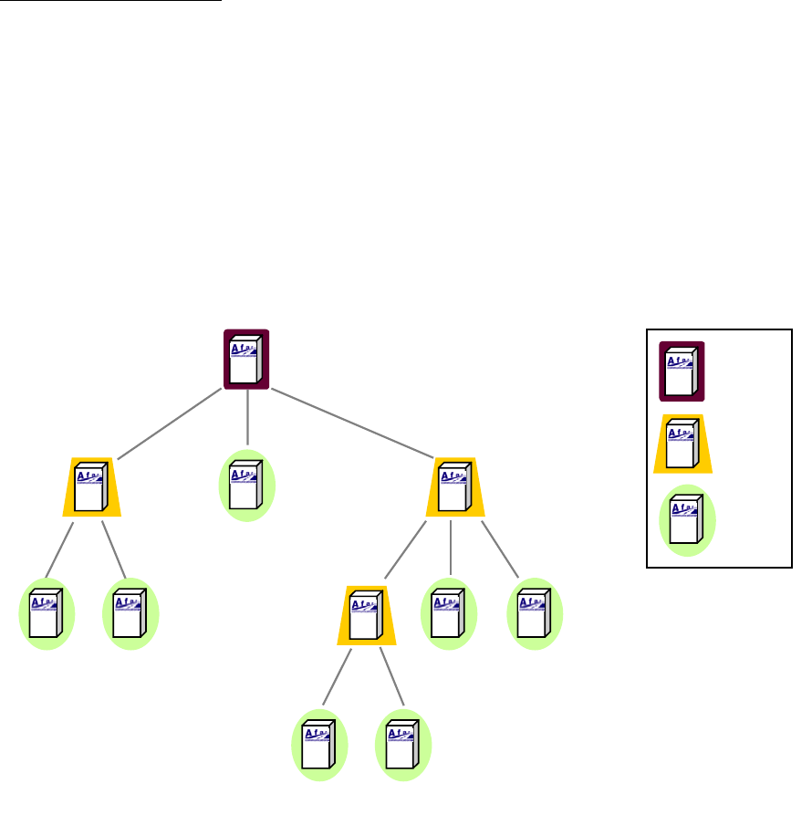
2.1.3 Tree topology
In a tree topology you have three node types: one root node and multiple branch and leaf nodes (use
the node command to configure the node type).
The root node performs a similar function to the hub in a point-to-multipoint topology and can have
up to 32 direct links to remote sites. The radios at the remote sites can be configured as either leaf or
branch nodes. A leaf node is similar to the remote in a point-multipoint topology. But a branch
node, besides having a link to a parent (root or another branch), also operates as an access point for
up to 32 additional remote nodes (children). Each of those nodes can again be configured as either a
leaf or a branch. There is no limit to the number of levels in the tree.
Root Root
Branch
Leaf
Figure 2.1 – Tree Topology
A branch node has two independent RF configurations, one for the link with the parent, the other for
the links with its children. Typically you set the link with the parent to use antenna A, and the link
with the children to use antenna B. This allows you to deploy a directional antenna pointing at the
parent node, while using an omni-directional or sectorial antenna for the links with the multiple
children. This is not mandatory, you can configure a branch radio to use a single antenna.
With a large network with many branch nodes you must pay special attention to the channel
assignments. One simple approach is to allocate non-overlapping channels to each “cell” (a cell
consists of a parent with all of its direct children). At the parent set both the transmit and receive
channel to the channel that you assigned to that cell. At the children set them to receive from the

pulsAR radio Operator’s Manual
2-4
parent in that same channel (see commands rf-1-setup and rf-2-setup). Once enough distance
separates cells you can start re-using overlapping channels.
The tree topology has the following features:
• There is no limit to the number of levels on the tree.
• Automatic association of new remote radios: just configure a new remote to receive on the
transmit channel of the desired parent, and it will automatically associate to the network (use the
“network-id” of the node command to prevent unauthorized radios from attaching).
• Self-learning bridging algorithm: the radios automatically learn the addresses of your equipment
attached on any of the LANs and route the packets using the minimal number of hops to reach
their destination.
• Self-healing network: If a parent node goes down a branch continues to operate and pass data
between its children. Once the parent recovers the branch automatically reattaches to the rest of
the network.
Dual antenna root mode: You also have the option of running the root with two antennas. This may
be useful if your remotes are grouped geographically such that you can use two directional or
sectorial antennas to cover each group. To run in this mode set the node type to root-2 and use rf-1-
setup and rf-2-setup to configure the RF parameters for each antenna.
Network throughput: A branch radio allocates half of the time to communicate with its parent and the
other half with its children. A root radio does not have a parent, so it divides its children into two
groups communicating with one group during the first half cycle, and with the second group during
the second half. Each of these two groups gets half of the total network capacity. Therefore in the
tree topology the maximum throughput available at one specific node in the tree is half of the total
network capacity. This is irrespective of the level in the tree, i.e., there is no further drop in
throughput as you go down the various levels.
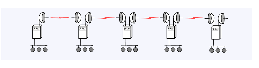
2.1.4 Linear Network
A Linear Network topology is ideal for providing communications in systems that naturally require
stations deployed along a line. Some of the applications are:
• Railway wayside communications
• Pipeline communications
• Highway roadside communications
• Long links that requires multiple repeaters between the end points
pulsAR radio Operator’s Manual
2-5
LAN
LAN
LAN
LANLAN
12345
Figure 2.2 - Linear Network Topology
You can easily implement a Linear Network as a subset of the Tree topology: configure the leftmost
radio as a root and all the radios in the network as a branch. Install each radio with two directional
antennas pointing at their two neighbors.
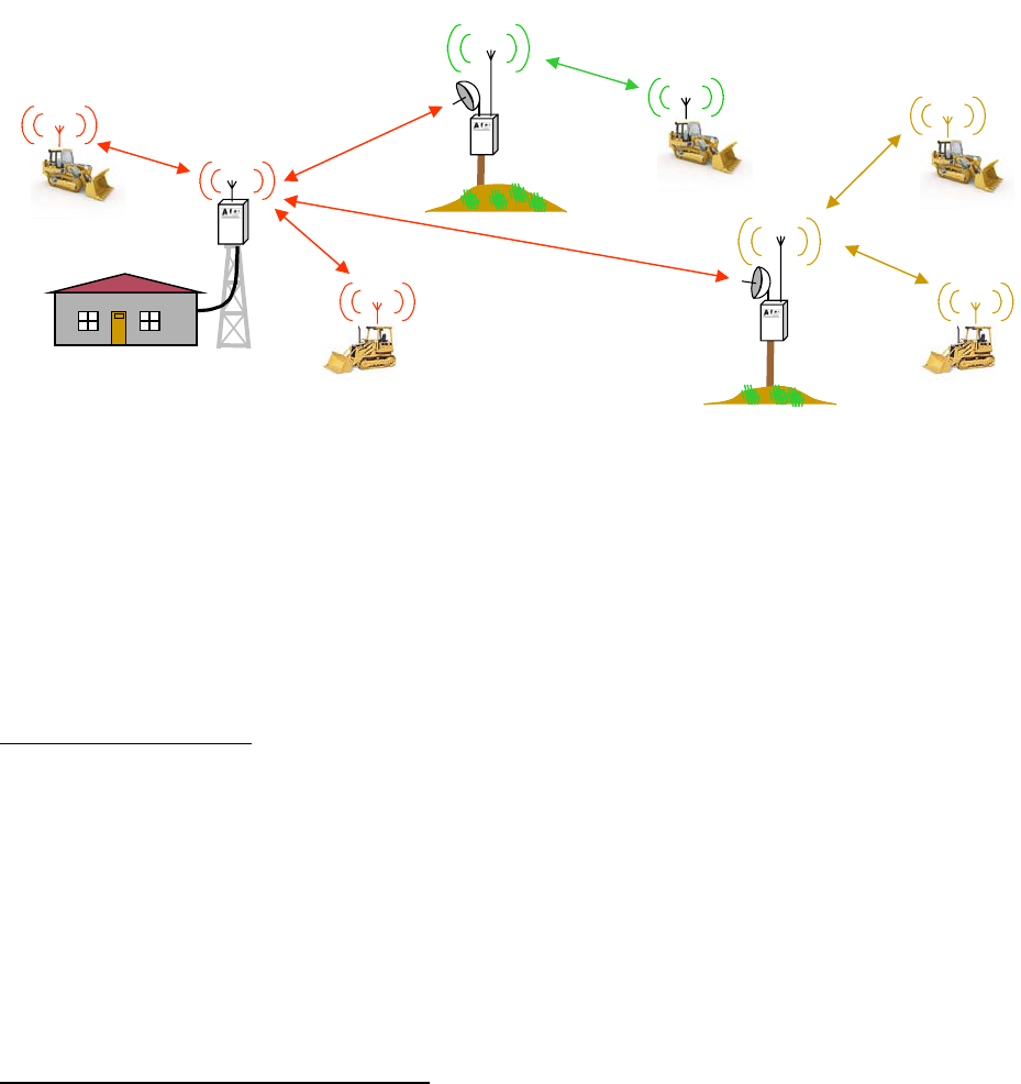
2.2 Roaming
With the roaming option, a remote or leaf radio can be configured with up to six different receive
channels (see command rf-1-setup). With this capability you can deploy multiple access points in a
region where a group of mobile radios will move around. Mobile radios attach to the network
through any of the access points and automatically switch to a new one whenever the need arises.
This capability is ideal for communications between a control center and vehicles, where the vehicles
must move beyond the range of a single hub radio.
All the access points are typically connected, through a backbone network, back to a central site.
This backbone network can be wired or wireless. You can use the tree topology and have each
branch and root serve both as access points and backbone nodes to bring the traffic back to the central
site (see figure).
The overall system supports the following features:
1. Mobile nodes automatically attach to the strongest access point.
2. As a mobile unit moves and the link to its parent fades, the mobile radio changes autonomously to
attach to a stronger parent.
3. Connectivity to a central site, through a backbone network, is maintained when a mobile changes
parent. Packet routing is switched over autonomously throughout the network so that packets are
correctly routed immediately after the mobile radio changes the access point.
4. Using the Tree topology you can use the fixed nodes in the tree (root and branches) to provide the
backbone network. Those same radios can also be the access points to the mobile leaf nodes.
This approach depicted in Figure 2.3.
pulsAR radio Operator’s Manual
2-6
.
Control center
branch
f2
branch
f3
root-1
f1
Figure 2.3– Roaming vehicles attaching to any of three access points
Each roaming radio decides on its own when to switch to another access point. If the signal strength
from the current parent drops down to a point where the link performance becomes compromised,
and there is a stronger signal from an alternate access point, then the mobile radio drops its current
link and reattaches to a stronger parent. Once it reattaches to the network, the roaming radio
broadcasts its new position so that all the equipment in the network will update their routing tables
accordingly. Overall the switch-over takes less than 250 ms.
Redundant hub operation: In a point-to-multipoint deployment it is often desirable to deploy the hub
site with two redundant radios. You can use the roaming feature to achieve this result. Configure the
two hubs to different non-overlapping channels. Configure all the remotes to roam between the two
hub channels. If one of the hub radios fail, or if there is interference in one of the channels, the
remote radios will automatically attach to the other hub.
In this application, since you would be co-locating the two hub radios, you need to pay attention to
the possibility of self-interference. Section 2.4 describes this issue and what you need to do to avoid
it.
2.3 Time Division Duplex
2.3.1 Fixed and variable cycle split
The PulsAR radio operates in Time Division Duplex (TDD) mode meaning that the radio switches
between transmit and receive over RF. In a point-to-multipoint topology this cycle consists of one
phase used for outbound transmissions (from parent to children) and a separate phase for inbound
transmissions (from the children to the parent). In the tree topology the cycle includes four phases: a
branch node first communicates with its children (transmit and then receive) and then with its
parent(receive and then transmit).
The radio provides two parameters that let you configure the TDD operation to best suit your
application. You can select the total cycle period between 20 and 40 ms and you can control the
cycle split to favor either outbound or inbound traffic. You only need to set these two parameters at
the hub or root node: all the children will pick up these TDD values from their parents.

pulsAR radio Operator’s Manual
2-7
A cycle period of 20 ms (default) results in lower latencies throughout the network. However there
will be more transitions between transmit and receive resulting in somewhat lower throughput
capacity for the network. A cycle period of 40 ms has the opposite effect.
For small networks a cycle period of 20 ms is usually preferred. If you have a network with many
nodes that are simultaneously active the 40 ms cycle will give you better performance.
The cycle split controls the percentage of time allocated for outbound traffic (from parent to children)
versus inbound traffic (from children to parent). The default is an automatic mode where the parent
radio allocates the split of each cycle dynamically based on the amount of traffic queued up in each
direction. In a tree network each parent decides this split independent of the other parents, based on
the local traffic conditions. In most deployment this setting gives you the best performance.
You can also specify a fixed cycle split. You have the choice of 9 different values in 10% nominal
increments from 10/90 (outbound/inbound) all the way to 90/10. You need to use the fixed TDD split
when you co-locate multiple radios and want to avoid self-generated interference. Refer to section
2.4 for details about synchronizing co-located radios. The fixed split may also be appropriate in
applications where the data traffic is constant and with pre-determined throughput.
2.3.2 On demand bandwidth allocation
The complete TDD cycle is divided into slots of approximately 1 ms each. In automatic cycle split
mode, the parent radio examines the total traffic queued up for outbound and inbound, and selects an
appropriate cycle split. With fixed cycle split this step is omitted.
For the outbound traffic, the parent radio allocates the bandwidth on demand to each remote. If there
is no traffic to a specific remote, the parent does not transmit any packets to that remote. When the
parent has packets to multiple children, it distributes the available bandwidth evenly so that all
children get equal throughput.
The parent starts every outbound transmission with a broadcast packet that includes the current cycle
split as well as the slot allocation for the inbound phase. All children decode this packet and only
transmit if they have been assigned one or more slots during the inbound phase.
When the children radios transmit they include a bandwidth request parameter informing the parent of
how much inbound traffic they have queued up. The parent allocates slots to the children based on
this information. On a given cycle, each child may be allocated zero, one, or several contiguous slots
to transmit. If the aggregate requested bandwidth exceeds the network throughput the parent divides
the available bandwidth fairly among the active children.
Once in a while the parent allocates a single slot to children that have remained idle to check if they
now have inbound traffic. This check only takes a single inbound slot and this slot is allocated
dynamically depending on current traffic load, available slots, and traffic history.

pulsAR radio Operator’s Manual
2-8
2.4 Radio co-location and interference
2.4.1 Radio co-location
As a network grows it often becomes necessary to deploy multiple radios at the same site. The
reasons to co-locate radios include the following:
1. In a Point-to-Multipoint or Tree network you want to achieve 360-degree coverage around a
central site, but would like to use sector antennas rather than one omni. Sector antennas have
higher gain than the omni and provide shielding from interfering signals originating at different
sectors. In this situation you might deploy a central site with six hub radios for example, each
one feeding a sector antenna covering 60-degree sectors.
2. The number of remote radios serviced by a single hub has grown to a point where the shared
bandwidth is no longer adequate. You may then add a second hub radio operating on a different
channel and split the remotes between two or more hubs.
3. You want to deploy two hubs to provide redundancy at the central site.
4. You want to deploy a repeater site with two “back to back” radios.
The problem is that when you co-locate two or more radios they can become the source of self-
interference, even if they are set to non-overlapping channels. The reason for this is explained in the
following section.
2.4.2 Co-located radios self-interference
The self-interference situation is illustrated in Figure 2.4, that shows radio A transmitting on channel
f1 while a co-located radio is trying to receive on channel f2. Because the antennas are in close
proximity antenna B will pick up a significant portion of the signal transmitted by radio A.
Figure 2.4 also shows a block diagram of the radio front end circuitry. It includes an RF filter to
reject out-of-band signals, followed by a Low Noise Amplifier (LNA), a second RF filter, Mixer and
finally the Intermediate Frequency (IF) filter. Channel selection occurs at the Intermediate Frequency
(IF), where the narrow band IF filter blocks out the other channels. This means that if the interferer
(radio A) is in close proximity, and is transmitting while radio B is trying to receive, it may saturate
the LNA or the Mixer of radio B. This results in radio B making errors even when it is set to a
different channel than radio A.
pulsAR radio Operator’s Manual
2-9
Radio
A
Radio
B
f1
f2
RF
Filter LNA RF
Filter
IF
Filter
Local
Osc.
IF
(undesired coupling)
freq
f2f1 freqIF
Figure 2.4– Co-located radio interference
The traditional approaches to reduce this self-interference include:
• Separate the antennas of the two radios further apart.
• Use different antenna polarization.
• Lower the transmit power of the interfering radio.
These approaches are limited and, at most, may allow you to co-locate three of four radios. The Afar
SPAN technology implements a synchronization scheme that completely eliminates this self-
interference allowing you to co-locate a much larger number of radios. This is explained in the
following sections.
2.4.3 SPAN Network synchronization
The PulsAR can be operated in a fixed TDD mode, where the complete cycle is divided into fixed
length outbound and inbound phases. You can specify this cycle split to be 50/50 or asymmetric.
When you co-locate multiple devices you must choose a fixed split and it must be the same for all the
co-located radios. The radios will then synchronize their cycle periods so that all co-located radios
transmit at the same time and then receive at the same time. This avoids the situation depicted in
Figure 2.4altogether. With a synchronized site you can then deploy upwards of 24 radios at the same
location.
The key to the synchronized SPAN network is the generation and distribution of the synchronization
information or heartbeat. At any site where there is more than one co-located radio, the various
radios detect each other, and automatically negotiate which should become the source of the
heartbeat. If that device later is turned off or fails, another device will take its place without user
intervention.
pulsAR radio Operator’s Manual
2-10
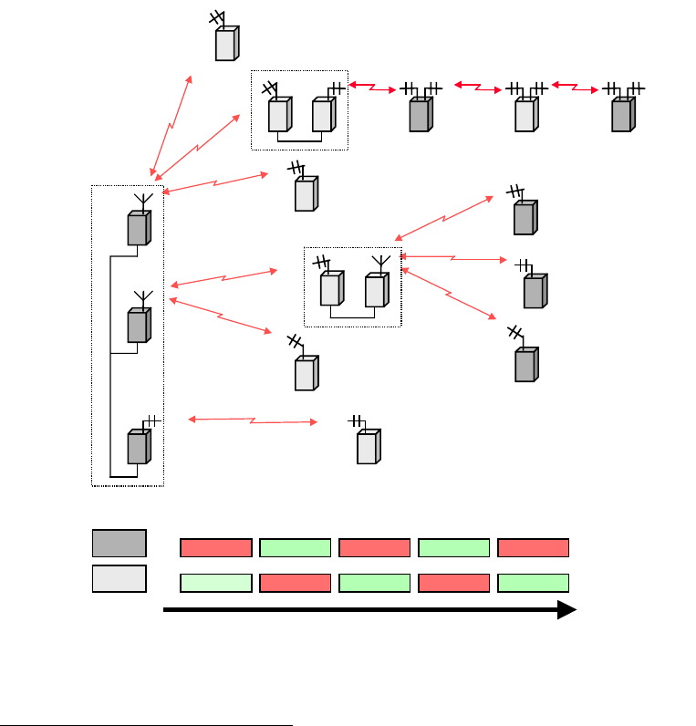
Figure 2.5 shows an example of a mixed network with multiple topologies. When the whole network
is synchronized each radio runs its TDD in one of two timings, A or B, as shown in the figure. All
radios at a single site run on the same cycle.
The following are guidelines you need to follow to achieve a successful synchronization in a complex
network:
1. At any site with multiple radios ensure that all radios are connected to the same LAN. The LAN
connection between radios must be FULL DUPLEX. Use the “>ether” command to check that
the radio Ethernet port is in full duplex (see also section 2.4.5 for synchronizing a site where the
radios are paired with NetCrossing Gateways).
2. You need to use a fixed TDD cycle split throughput the network. If you are co-locating multiple
hubs or roots in a point-to-multipoint or tree configurations, choose any split appropriate for the
traffic in your network. You must use the same value in all co-located radios.
3. When you co-locate all hubs or all roots, you may use a cycle period of either 20 or 40 ms, but it
must be the same in all co-located devices. You can mix hub and root radios at the same site, but
in that case you must set the hubs cycle periods to 20 ms and the roots to 40 ms.
4. You can also co-locate a remote (or a leaf or branch) with other radios. However children nodes
have their cycles synchronized to their parents. So at one given site there can only be one child
node, which will become the source of the heartbeat. The other radios at that site must be hubs or
roots. In this situation choose an even cycle split of 50/50.
5. Make sure that all radios have the tdd sync-mode set to auto (default).
If you follow these guidelines the radios will spread the synchronization across the network and
completely avoid self-interference. Use the “>show” command to find which radio is the source for
the heartbeat at that site and also whether there are any conflicts in the configuration.
pulsAR radio Operator’s Manual
2-11
A
B
B
B
B A B A
LAN
A
B
B
A B
B
A
A
A
Tx Rx Tx Rx Tx
Rx Tx Rx Tx Rx
Time
(A)
(B)
Figure 2.5– Multiple Topology Network
2.4.4 Heartbeat suppression
There are situations when the multicast of heartbeat packets may not be necessary, and would put an
unnecessary burden on the Ethernet. The radios detect these situations automatically and suppress the
multicast of the heartbeat packets when there is no co-located device to receive them.
You may need to co-locate radios and do not wish them to try and synchronize to each other. For
example, if the connection between LAN ports of the radios goes through bridges that insert variable
delays on the Ethernet packets, the synchronization protocol may not work properly. In these cases
you can turn off the radio participating in the synchronization protocol by setting the tdd sync-mode
to off. This is also the appropriate setting if multiple co-located radios get synchronization over RF
and therefore cannot accept a heartbeat over the Ethernet.. In these cases you need to avoid self-
interference with the more traditional methods of increasing the separation between antennas, and/or
reducing transmit power
pulsAR radio Operator’s Manual
2-12
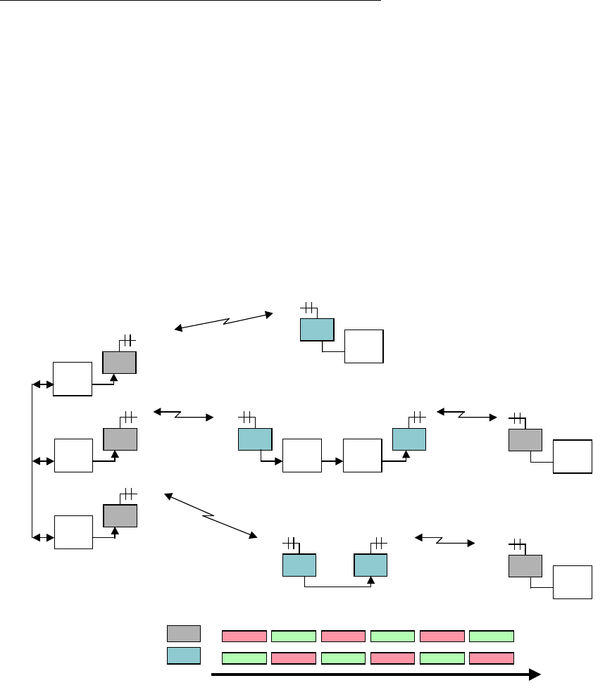
2.4.5 Synchronization with NetCrossing Gateways
The Afar NetCrossing Gateway devices convert between a synchronous serial data stream and
Ethernet packets. They can be paired with the PulsAR to establish wireless point to point serial
synchronous links. When you have multiple such links and need to co-locate radios, the gateways
can participate in the heartbeat negotiation and site synchronization. The gateways are equipped with
a SYNC port through which they propagate the synchronization information, without having to
connect the radio LANs together.
Figure 2.6 shows a network with mixed radios and gateways (NxG) and illustrates how the SPAN
synchronization is achieved.
In the gateways the tdd sync-mode can be set to three different values: off (which is the default),
auto, and master. The figure shows the appropriate setting of each gateway. All radios should have
the tdd sync-mode configured to the default auto setting.
Tx Rx Tx Rx Tx Rx
Rx Tx Rx Tx Rx Tx
Time
(A)
(B)
NxG 2
Sync
Radio
2 (A)
NxG 3
Sync
Radio
3 (A)
tdd sync=master
NxG 1
Sync
Radio
1 (A)
NxG 4
Sync
Radio
4 (B)
tdd sync=off
NxG 5
Sync
Radio
5 (B) NxG 6
Sync
Radio
6 (B) NxG 9
Sync
Radio
9 (A)
tdd sync=auto tdd sync=off
Radio
7 (B)
Radio
8 (B) NxG 10
Sync
Radio
10 (A)
tdd sync=off
Figure 2.6– Synchronization with NetCrossing Gateways
The site on the left shows three gateways, each one connected to a respective radio. These radios are
co-located and therefore their TDD cycles need to be synchronized to avoid self-interference. Since
their LAN ports are not connected to each other the synchronization is achieved through the SYNC
ports of the gateways. You must connect all the SYNC ports together in a daisy-chain manner, and
configure the gateways tdd sync-mode to master. In master mode each gateway keeps a cycle timer
running, synchronized to the other gateways. This synchronization is shared, i.e. no single gateway
is the synchronization source. In fact any gateway can be added or dropped without affecting the
cycle timers of the remaining gateways.

pulsAR radio Operator’s Manual
2-13
You must configure the three left radios as the “hub” for their RF links. Each of these three radios
detects the presence of the respective gateway, which becomes the source of its heartbeat over the
Ethernet. In this way, all three radios run their cycle times synchronized and following timeline A in
the figure.
The middle site in the figure illustrates another way in which the gateways participate in the cycle
synchronization. At this site radio 5 is a “remote” with its cycle synchronized to radio 2 across the
RF link. Radio 5 therefore becomes the source of the heartbeat at this site. It sends heartbeat packets
over the Ethernet, which synchronize the cycle timer of gateway 5. As shown in the figure you must
connect gateway 5 and 6 SYNC ports together and configure their tdd sync-mode to auto. In this
mode the gateways propagate the heartbeat between the Ethernet WAN port and the SYNC port.
Gateway 5, which receives heartbeat packets from the radio, drives the SYNC port. Gateway 6
synchronizes its cycle timer to the SYNC port and sends heartbeat packets to radio 6. The two co-
located radios at this site have their cycle times synchronized, following timeline B. At this same site
you could have more pairs of gateways and radios. You would connect the SYNC lines of all the
gateways together and configure their tdd sync-mode to auto.
At the sites where there is a single radio and gateway you should set the gateway tdd sync-mode to
off. Since there are no co-located radios this setting turns off the generation of heartbeat packets
which are unnecessary.
2.5 Ethernet Bridging
2.5.1 Self-learning bridging
The radio operates the Ethernet port in a self-learning bridge mode. It configures the port in
promiscuous mode, i.e., it examines all the Ethernet packets that are flowing in the local LAN. Since
these Ethernet packets contain a source and destination address, the radio quickly learns the
addresses of all the local stations connected to the LAN (all the source addresses of packets flowing
in the LAN are local).
As a radio receives packets over RF it also learns the addresses of stations that can be reached across
that RF link. For a hub radio in a PmP topology, the radio keeps track of which addresses are
associated with each remote.
With this information on hand, each radio examines the destination address of every Ethernet packet
in the local LAN and makes one of the following decisions:
1. If the destination address is for a local station, discard the packet.
2. If the destination address is associated with a remote radio, queue that packet to be forwarded to
that remote radio. Note that for a PmP topology, the hub radio keeps multiple output queues, one
per remote radio.
3. If the station address is unknown or is a broadcast send the packet to all the remote radios.
Each device has capacity to store 500 entries in its Ethernet table. Entries are erased after a certain
amount of time to allow for stations to be moved between LANs and not show up in two distinct
LANs. You can control this time-out with the “ethernet” command. If the table ever gets full, entries
that have been least used are erased to make room for new entries.
You can examine the table of ethernet addresses and their respective nodes with the command:

pulsAR radio Operator’s Manual
2-14
>show ethernet
2.5.2 Packet priorities
As packets arrive into a radio from any port, the bridging algorithm determines if the packets need to
be transmitted over RF. If so the radio queues the packets into one of several priority queues.
Starting with the highest priority the packets are classified as follows:
• Vital packets: These are UDP packets with a specific destination UDP port number. This port
number is part of the field programmable radio configuration (see command >udp).
• NetCrossing Gateways Serial packets: These are SNAP encapsulated packets containing
synchronous serial data generated by the Afar NetCrossing Gateway devices.
• High-Priority: These includes network management packets for “ECON” command sessions, and
also IP packets with a value in the “Type-Of-Service” indicating high priority. The radio
interprets the IP TOS field per the IETF differentiated services (DS) definition as shown below:
01234567
Codepoint Unused
When the codepoint field has the value xxx000, the three most significant bits are interpreted as
precedence bits. The radio gives high priority to packets with a precedence field of 6 or 7. In
hexadecimal notation this translates into TOS values of E0 and C0.
• Low-priority: All other packets
When the time to transmit over RF arrives, the software always takes packets from the higher priority
queues first.

pulsAR radio Operator’s Manual
3-1
3 INSTALLATION AND SETUP
NOTE
Appendix F contains a quick set up diagrams showing the minimum configuration and commands
necessary to put up a point-to-point link and a point to multipoint network.
3.1 Bench Check Out
It is recommended that an initial check be performed on the bench before a field installation.
For this bench check out you need two PulsAR units. Radio 1 will be configured as the hub and radio
2 will be configured as a remote. The first approach described below uses the “Ethernet Console
Program” to emulate the terminal across an Ethernet connection. The second approach uses two
terminals connected to the auxiliary port of the radios.
3.1.1 Using the radio Ethernet connection
In order to use the Ethernet connection you need the “Ethernet Console Program” (Econsole)
provided in the CD. See Appendix D for installation instructions for Econsole. Once Econsole is
installed, perform the following steps.
1. Connect the PC Ethernet port to the “To LAN” connector of the Power Inserter Unit of radio 2.
Use an Ethernet crossover cable if connecting the PC directly to the Power Inserter Unit, or use a
straight cable if connecting through a hub.
2. Connect each Power Inserter Unit to the respective PulsAR using a CAT 5 cable as defined in
section 1.
3. Connect each radio Antenna A port (N type connector) to an appropriate 2.4 GHz band antenna
using an RF coaxial cable.
4. Connect the two Power Inserter Units to a power outlet of the appropriate voltage.
5. At the PC open a DOS window and invoke the Econsole program by typing:
> econ
If only one radio is connected to the LAN, ECON will establish a connection with that radio. If
more than one radio are in the same LAN, ECON provides a list of all radios found (see
Appendix D for more detailed instructions on the use of Econsole). Once a connection to the
radio is established, the radio outputs a prompt with the following format:
rmt-nnnnn #>
where nnnnn are the last five digits of the radio serial number. The first three letters may read
hub or rmt. If the radio had previously been configured the prompt will be the radio name.

pulsAR radio Operator’s Manual
3-2
6. Set radio 2 to its factory default configuration by typing the commands:
> load factory
> save-configuration
7. Move the Ethernet cable from the radio 2 power inserter to the power inserter connected to radio
1. At the DOS window invoke once again the Econsole program. Configure radio 1 by typing
the commands:
> load factory
> node type=hub
> save-configuration
8. Once radio 1 is configured as the hub it will establish a RF communication with radio 2. To
verify this connection type:
> show
Check that the radio status shows “MASTER IN SYNC”, and that the number of remotes is 1.
You may also type >show radios to see various statistics of the link with radio 2.
9. Once the link is established, Econsole can be used to configure the local or the remote radio. In
order to switch the Econsole connection, logout of the current connection and re-invoke
Econsole:
> logout
> econ
Econsole will list the two radios and give a choice to connect to either. Section 4 describes the
command language used to further modify the radio’s operating parameters.
3.1.2 Using the radio auxiliary port
1. Connect each PulsAR Console Port to a terminal, or a PC running a terminal emulation program.
Configure the terminal settings as follows:
Baud rate: 9600
Word length: 8 bits
Parity: none
Stop bits: 1
2. Connect each Power Inserter Unit to the respective PulsAR using a CAT 5 cable as defined in
section 1.
3. Connect each radio Antenna A port (N type connector) to an appropriate 2.4 GHz band antenna
using an RF coaxial cable.
4. Connect the two Power Inserter Units to a power outlet of the appropriate voltage.
5. The radios output a banner identifying the software and hardware versions and serial number,
followed by the command prompt with the following format:
rmt-nnnnn #>
where nnnnn are the last five digits of the radio serial number. The first three letters may read
hub or rmt. If the radio had previously been configured the prompt will be the radio name.

pulsAR radio Operator’s Manual
3-3
6. Set radio 2 to its factory default configuration by typing the command:
> load factory
> save-configuration
7. Configure radio 1 by typing the commands:
> load factory
> node type=hub
> save-configuration
8. Once radio 1 is configured as the hub it will establish a RF communication with radio 2. To
verify this connection type:
> show
Check that the radio status shows “MASTER IN SYNC”, and that the number of remotes is 1.
You may also type >show radios to see various statistics of the link with radio 2.
9. The terminal connected to each radio can be used to further modify the radio’s operating
parameters. Section 4 describes the command language used to perform those functions.
3.2 Field Installation
3.2.1 Mounting Bracket installation
The radio is shipped with mounting hardware designed to easily mount the unit onto a pole outdoors.
You can secure the radio to poles of up to 2.5 inches (6.3 cm) in diameter.
Before taking the radio into the field, assemble the mounting hardware as follows:
1. Using the two screws provided, secure the flat aluminum plate into the recessed channel on the
back of the unit. Also install the provided ground lug for connection to the earth ground as
described in step 3 of the section below.
2. Thread the L shape bolt into the hole of the V shape bracket. The non-threaded segment of the
bolt should be outside of the V bracket.
In order to secure the radio outdoors place the radio against a pole with the RF connectors facing up
(see Figure 1.1). The back of the radio enclosure has four guiding feet that prevent it from sliding
from side to side. Place the V bracket around the pole, sliding its two grooves up into the aluminum
plate on the back of the radio. Once the grooves reach the stops, manually tighten the L shaped bolt
so that it “bites” into the pole.
Afar also provides a different bracket for mounting the radio against a flat surface.

pulsAR radio Operator’s Manual
3-4
3.2.2 Earth Grounding
For an outdoor installation you must provide a solid ground connection between the PulsAR metal
enclosure and the Earth ground. This will minimize possible damage due to static buildup or nearby
lightning.
If you install a lightning arrestor (Afar part no SUR-0205) on the antenna connector follow these
same directions but connect the grounding cable to the appropriate lug of the arrestor rather than the
radio. A RF lightning arrestor is only recommended in locations where it is warranted and you use a
coaxial cable of lengths exceeding 10 feet (3 m).
Each radio is shipped with a small ground lug (part no. SLU-35), and a lock washer to facilitate the
installation of the ground connection.
You will require some additional supplies that are easily found at a hardware store, namely:
• AWG #6 copper grounding cable (4.1 mm diameter).
• Grounding lug, nut, bolt, lock washer (as required) for attaching the cable to the metal
tower or structure.
• Anti oxidizing paste
• Outdoor cable ties (as required)
The following steps describe a procedure for a proper Earth ground connection:
1. Select an adequate grounding point on the tower or structure near the radio. This point should be
below the unit and must not be inside the building. If you must drill a hole make sure it is NOT
in the tower supports or cross braces. If several outdoor units are installed in the same area you
may use the same grounding point.
2. Apply a thin film of anti oxidizing paste to both sides of the supplied grounding lug blade, as well
as the threads of the screw used to secure the lug.
3. Install this grounding lug onto the radio enclosure with one of the two screws used to secure the
mounting plate. This screw must go through (i) the lock washer, (ii) the grounding lug blade, (iii)
the radio mounting plate and finally into the enclosure, in that order. Insure that the cable
connector of the grounding lug is pointing downward.
4. Prepare the grounding cable by stripping an adequate amount of insulation from both ends and
apply anti oxidizing paste to the exposed copper.
5. Insert one end of the exposed cable into the radio ground lug and tighten the screw on the lug.
6. Use steel wool or sand paper to clean the grounding point on the metal tower or structure.
7. Apply a thin film of anti oxidizing paste to this grounding point surface.
8. Fasten the cable to the grounding point using a lug, bolt and nut as required.
9. If required secure the cable to the tower or structure with cable ties or clips. DO NOT bundle this
grounding cable with any other cable used for data, power or RF.

pulsAR radio Operator’s Manual
3-5
Cautions
When using the anti oxidizing paste read and follow the instructions and warnings for the selected
product. In addition you should note the following general guidelines:
• The paste will act as a lubricant, therefore always use lock washers.
• DO NOT apply the paste to RF and data cable connections: the anti-oxidizing paste is conductive
and may degrade the performance or damage the equipment.
• DO NOT use electrical or other tape for sealing the grounding connections when using anti
oxidizing paste
• DO NOT use thread-locking compound on the same screw with anti oxidizing paste.
Inspect the grounding connections on a regular basis as well as after a lightning strike. Look for
cables that may have been damaged or connections that may have loosen up or oxidize over time.
Replace any damaged cables or connectors and tighten any loose connections.
3.2.3 Power/Ethernet cable
Connect the outdoor cylindrical connector of the CAT5e cable to port D of the radio. The other end
of this cable (with an RJ45 connector) plugs into the indoor Power Inserter Unit.
You can optionally install the Ethernet/Power Surge Suppressor module (SUP-0202) at the point
where the CAT5e cable enters the building. This protects your indoor equipment against surges
induced by nearby lightning on the outdoor CAT5 cable. The surge suppressor has two RJ45
connectors and a ground wire, which you must connect to an earth ground.
If you use a DC source to power the radio, make sure you do not exceed the CAT5e cable length
specified in the table below. At port D the radio requires a minimum of 9.5 VDC (and a maximum of
58 VDC). With the DC voltages shown at the power inserter, the maximum cable length results in an
input voltage at the radio of 9.5 VDC. The radio includes a voltage monitor which you can read with
the >show command. This can be useful to determine the status of your battery for a battery-powered
installation.
DC voltage Maximum CAT5e cable length
(at power inserter) (feet) (meters)
10 51 16
11 153 47
12 255 78
13 358 109

pulsAR radio Operator’s Manual
3-6
3.2.4 Antenna Installation
NOTICE
The antennas for the pulsAR radios must be professionally installed on permanent structures for
outdoor operations. The installer is responsible for ensuring that the limits imposed by the applicable
regulatory agency (FCC, IC, or CE) with regard to Maximum Effective Isotropic Radiated Power
(EIRP) and Maximum Permissible Exposure (MPE) are not violated. These limits are described in
the following sections.
The pulsAR radio is typically attached to a pole (with the clamp provided) with the antenna
connectors facing up. For optimum performance the radio must be mounted in close proximity to the
antenna with a cable run typically under 2 meters (6 feet). Afar carries several antennas for operation
at either 900 MHz or 2.4 GHz as shown below:
Band Antenna Type Gain AFAR Model Number
Omni-directional 5 dBi ATO-0905
900 MHz
Dish Reflector 15 dBi ATD-0915
Omni-directional 9 dBi ATO-2409
2.4 GHz
Dish Reflector 24 dBi ATD-2424
Antennas at each end of the link must be mounted such that they have the same polarization, and
directional antennas must be carefully oriented towards each other. The choice of polarization
(horizontal vs. vertical) is, in many cases, arbitrary. However, many potentially interfering signals
are polarized vertically and an excellent means of reducing their effect is to mount the system
antennas for horizontal polarization. Of those antennas listed above, the directional antennas can be
mounted for horizontal or vertical polarization, while the omni-directional antennas can only be
mounted for vertical polarization.
Proper grounding of the antenna is important for lightning protection as well as to prevent electrical
noise interference from other sources. The antenna should be mounted to a mast or tower that is well
grounded to Earth. Use weatherproof connectors in all outdoor couplings. Also use the “coax-seal
tape” (included with the radio) to further weatherproof outdoor connections.
If the coaxial cable between the radio and antenna exceeds 10 ft (3 m) you may also want to install a
lightning arrestor device at the N type connector of the radio (Afar part no SUP-0205). For short
coaxial cable lengths you do not need a RF lightning arrestor device.
3.2.5 Antenna Alignment
When mounting the high gain antenna (24 dBi), the proper antenna alignment is extremely important
since the beam-width of the antenna is very narrow. Once you perform a rough alignment and the
link is in operation, you can use the “monitor-link” and “antenna-alignment-aid” commands. Type:
> monitor-link

pulsAR radio Operator’s Manual
3-7
in order to update, every half second, the link statistics including the RSSI level. The antenna can
then be aligned so that the RSSI is maximized. In the PmP topology, the hub antenna is typically an
omni and dose not need to be carefully aligned. But if you need to align a hub radio antenna for
maximum signal from a particular remote use the command:
> monitor-link node=N
where N identifies the remote per the table displayed with the show command
Since in many applications the antenna is on a tower where it is not practical to have a terminal
nearby, the pulsAR radio provides an “antenna alignment aid” available at the outdoor unit. This
feature uses the three pin “Auxiliary port” connector to output an audio signal with a pitch
proportional to the receive signal strength. AFAR provides a special cable adapter that converts the
three-pin connector into a standard female audio jack. Use this cable to connect the three-pin
connector to a pair of standard headphones while aligning the antenna. At a terminal session issue the
command:
>aaa audio (aaa is an abbreviation for “antenna-alignment-aid”)
and then align the antenna until you hear the highest audio pitch. Once the antenna is aligned you
may type the command:
>aaa off
to turn off the audio signal and revert the auxiliary port connector to console mode.
3.2.6 Radio Configuration
The pulsAR units are shipped pre-configured with a factory default configuration. If the unit
configuration has been altered, you can always reload it with the command:
> load factory
In order to deploy an RF network between two or more radios you need choose one radio to be the
“hub” and configure it with the command:
> node type=hub
All other radios may be left configured with the factory configuration. As you turn them on with
antennas pointing at the hub they will automatically join the network. Use the >show command to
see the status of the radio, or the >show radios command for a complete list of all the radios in the
network.
In most installations you may want to change several other parameters. The table below shows the
most common ones and the associated commands to change them. Refer to section 4 for a complete
description of each command.

pulsAR radio Operator’s Manual
3-8
Parameter Description Command
RF channel You may need to change the RF channels if there is interference
on the default channel (12). You can configure the RF transmit
channel independently from the RF receive channel. Refer to
section 3.2.7 for the procedure for choosing new channels.
rf-1-setup
rf-2-setup
RF transmit
power
The factory default is 18 dBm. You can configure this parameter
in 1 dB increments from 0 to its maximum value (model
dependent). Take care not to exceed the maximum power limits
as described in sections 3.2.8 or 0
rf-1-setup
rf-2-setup
Network ID The default value is 0. Change this value in all radios to a unique
number to avoid unauthorized radios from joining the network
node
3.2.7 Spectrum Analysis and channel selection
Radio operation in unlicensed bands has the potential of suffering from interference from other
equipment operating in the same band. The use of directional antennas greatly reduces the potential
for interference. In addition, the pulsAR radio includes several features, described below, to identify
and overcome sources of interference.
The radio can be commanded to perform a spectrum analysis of the ISM band and report the results in
either a graphical or tabular form. The command:
>spectrum-analysis antenna=a dwell=xx
instructs the radio to scan the entire band, dwelling on each channel for a programmable amount of
time, and record the highest signal level in that channel. This feature can be used to perform a site
survey and identify the best receive channel.
Note that the RSSI value reported for each channel represents the total energy within the radio RF
bandwidth centered around that channel. The radio RF bandwidth depends on the pulsAR model and
can be 1.7, 4.6, or 17 MHz (see specification on appendix ). When you do a spectrum analysis any
single channel sample that shows a low “noise” level, is a good candidate to select as a receive
channel.
Once you identify a potential receive channel using the spectrum analysis tool, you may then use the
“timing analysis” feature to confirm that the selected channel is indeed clear. The command:
>time-analysis channel=xx antenna=a dwell=xx
instructs the radio to dwell on the specified channel for the specified amount of time. After taking
several samples the radio displays the signal level detected in that channel over time.

pulsAR radio Operator’s Manual
3-9
3.2.8 Output Power Limits (FCC)
The Federal Communications Commission (FCC) regulations limit the maximum Effective Isotropic
Radiated Power (EIRP) for spread spectrum systems operating in the 900 MHz or the 2.4 GHz band.
The tables below show the maximum allowed output power using the various antennas.
Maximum Output Power (dBm) – 900 MHz models
Antenna Gain
5 dBi 15 dBi
AR-9010E
AR-9027E
27 19
\
Maximum Output Power (dBm) – 2.4 GHz models
Antenna Gain
9 dBi 24 dBi
AR-24010E
AR-24027E
AR-24110E
27 24
Maximum Output Power (dBm) – 2.4 GHz models
3.2.9 Output Power Limits (CE)
The European Telecommunications Standards Institute (ETSI) regulations impose a limit of 20 dBm
as the maximum Effective Isotropic Radiated Power (EIRP) for direct sequence spread spectrum
systems operating in the 2.4 GHz band. In addition the maximum spectral power density is limited to
10 dBm per MHz maximum EIRP. Of these two limits the power density is the most restrictive for
this radio. The installer must reduce the output power of the pulsAR radio so that the EIRP of the
radio does not exceed TBD dBm. The antenna gain, cable and connector losses must be taken into
account when computing the maximum output power.
3.2.10 Maximum Permissible Exposure (MPE) Limitations
The installer must mount all transmit antennas so as to comply with the limits for human exposure to
radio frequency (RF) fields per paragraph 1.1307 of the FCC Regulations . The FCC requirements
incorporate limits for Maximum Permissible Exposure (MPE) in terms of electric field strength,
magnetic field strength, and power density.
Antenna installations must be engineered so that MPE is limited to f/1500 mW/ cm2 (at 900 MHz) or
1 mW/cm2 , (2.4 GHz) the more stringent limit for "uncontrolled environments". The table below

pulsAR radio Operator’s Manual
3-10
specifies the minimum distance that must be maintained between the antenna and any areas where
persons may have access, including rooftop walkways, sidewalks, as well as through windows and
other RF-transparent areas behind which persons may be located.
900 MHz - Minimum Distance calculation to
avoid Antenna Radiation Hazard (exposure of 0.610 mW/cm2)
Antenna Gain (dBi): 5 15
Max. Output Power 27 19
MPE safe distance (cm) 20 20
2.4 GHz - Minimum Distance calculation to
avoid Antenna Radiation Hazard (exposure of 1 mW/cm2)
Antenna Gain (dBi): 9 24
Max. Output Power 27 24
MPE safe distance (cm) 25 25
*NOTE: For fixed location transmitters, the minimum separation
distance is 2 m, even if calculations indicate a lower MPE distance. For
mobile transmitters the minimum is 20 or 25 cm (shown on the tables)
3.3 Upgrading the Firmware.
3.3.1 Description
The operational firmware for the pulsAR radio is stored in Flash PROM and can be easily updated.
The Flash PROM can hold multiple versions of the firmware simultaneously. The table below lists
some of the “File Utility” commands used to download and manage the various files stored in Flash
PROM. A more detailed explanation for each command can be found in section 4.
File Utility command summary
Command Description
directory Lists all files stored in Flash PROM
delete-file filename Deletes the specified file from the directory
download-file path/filename Downloads the specified file from the PC path/filename
into the Flash PROM
set-default-program filename Sets the indicated filename as the default program to run
after power up
run-file filename loads the indicated program into RAM and executes it.

pulsAR radio Operator’s Manual
3-11
New firmware versions are made available from time to time at the following page in our website:
http://www.afar.net/support.htm
The firmware files (for point-to-multipoint) are named:
pmp0x_xx.bze (binary zipped file for downloads through the Ethernet port)
pmp0x_xx.dwe (ascii file for download through the serial port, or via Telnet)
where 0x_xx is the firmware version number. The website contains instructions for transferring the
files into your PC.
A new file can be downloaded into the radios in one of three ways: (1) Using the “econ” program
running in a PC connected to the same physical LAN as one of the radios. This is the fastest method
and allows you to download to multiple radios from the same PC. (2) Using a Telnet session from
anywhere on the Internet. This requires the radio to have been pre-configured with an IP address. (3)
Using a terminal emulator program (e.g. HyperTerminal) running on a PC connected through the
serial port to the radio RS-232 auxiliary port. This method only allows you to download to that
specific radio.
The next three sections explain in detail how to download a new file using each method.
3.3.2 Installing new firmware through the Ethernet port
This procedure assumes that the new firmware needs to be installed in all radios of a working
network. The upgrade is performed from a single PC connected via Ethernet to one of the radios.
Note that new firmware does not need to be compatible with the firmware currently running. You
can still download incompatible firmware and restart the network from a single location.
1. If you have not done so, install the utility program “econ” in the PC. This utility program is
distributed with the radios and can also be downloaded from the website. Please refer to
appendix D for instructions on how to install this utility.
2. Make sure the file with the new firmware (file pmp0x_xx.bze) is available in the PC.
3. Start the econsole utility by typing “econ” from a DOS window. Econ will send a “discovery”
message and display all the radios that can be seen. Verify that all radios in the network are
listed. Then select one of the radios in the list that you wish to upgrade.
4. Issue the command:
>directory
to view a list of files stored in Flash PROM as well as the available free space. Verify that the
free space in flash PROM is larger than the size of the pmp0x_xx.bze file in the PC. If there is
not enough space in Flash PROM delete one of the program files to make up space (use command
>delete filename).
5. If the radio configuration has been password protected, you must first unlock the protection with
the command:
>unlock enable-configuration=password
pulsAR radio Operator’s Manual
3-12
(when the configuration is unlocked, the radio prompt ends with the characters ‘#>. In locked
mode the prompt does not include the ‘#’ character).
6. Issue the command:
>download path/pmp0x_xx.bze
where path/ is the directory in the PC where the pmp0x_xx.bze file is stored. The path/ extension
is not required if the file is in the same directory as the ECON program. As the download
proceeds econ displays a line showing the current percentage complete.
7. Once the download is complete, issue the command:
>set-default-program pmp0x_xx
in order to make the new file the default program to run after a reset.
8. Issue the command:
>single-node-reboot timeout=60
in order to speed up the network recovery after rebooting the hub radio below (this step is not
necessary if the new firmware is known to be compatible with the old one but it does not hurt in
either case).
9. Depress the “F4” key to log-off the session with the current radio. “Econ” displays the list of all
radios from the initial discovery phase. Select another radio in the network and repeat steps 4
through 8 for each of the radios.
10. Once all radios in the network have the new program, log onto the hub radio (using econsole) and
issue the command:
>reboot
to cause that radio to restart using the new firmware.
11. If the new firmware is compatible with the old one, the links will be reestablished in a short time
(with the hub running the new version and the remotes running the old version).
If the new firmware is incompatible with the old one, the links to the remotes will not be
reestablished. In this case, after 60 seconds, the remote radio will reboot. They will then load the
new firmware and be able to reestablish the links with the hub.
12. Wait at least ten seconds from the moment you entered the reboot command, then press <CR>.
Econsole automatically attempts to reconnect to the same radio. Once a new session with that
radio is reopened issue the command:
> version
and check that the radio is indeed executing the new version.
13. Depress the “F4” key to log-off the session with the hub radio. “Econ” displays the list of all
radios from the initial discovery phase. Select a different radio and issue the command:
>version

pulsAR radio Operator’s Manual
3-13
and check if that radio is running the new or old version. If the radio is already running the new
version repeat this step with the next radio. Otherwise perform the next step.
14. If the radio is running the old version issue the command:
>reboot
Wait at least ten seconds for the radio to perform its start up code and re-establish the link. Then
press <CR>. Econsole automatically attempts to reconnect to the same radio again. Once a new
session with that radio is reopened issue the command:
>version
and check that the radio is indeed executing the new version.
Note that the file downloads are executed with the link in full operation. The only downtime in the
link occurs when the radios are rebooting. The radio configuration is kept intact when a new version
is started. The downtime for the radio being restarted, is typically less than twenty seconds. When
upgrading to an incompatible version, the downtime will be slightly over one minute.
3.3.3 Installing new firmware using Telnet
Telnet is a protocol that allows you to conduct a remote radio command session from a local host.
The radio must have been pre-configured with an IP address and be reachable, over the network, from
the local host. Refer to section 5 for details on how to configure a radio IP address and initiate a
Telnet session. The Telnet terminal emulation must have the capability of sending an ASCII file to
the remote machine. The following description assumes you are using Hyperterminal as the local
Telnet terminal emulation.
1. Verify that the new software is available in the local machine. The download software for
upgrade via Telnet must have a “.dwn” extension, e.g., pmp03_25.dwn.
2. Initiate a Telnet session with the radio as described in section 5.
3. If the radio configuration has been password protected, you must first unlock the protection with
the command:
>unlock enable-configuration=password
(when the configuration is unlocked, the radio prompt ends with the characters ‘#>. In locked
mode the prompt does not include the ‘#’ character).
4. Issue the command:
>directory
to view a list of files stored in Flash PROM as well as the available free space. Verify that there
is enough free space in flash PROM for the new file. The space required will be the size of the
pmp0x_xx.dwn file divided by 2.5. If there is not enough space in Flash PROM delete one of the
program files to make up space (use command >delete filename).
5. Start the download process by typing:
>download-file destination=pmp0x_xx method=inline
where 0x_xx file is new version of software being installed.

pulsAR radio Operator’s Manual
3-14
6. The radio will return with the following:
“Send the file ... if incomplete, end with a line with just a period”
When you get this prompt, go to “Transfer-Send Text file…” in Hyperterminal and select the file
to be installed. The file must have a “.dwn” extension.
7. After the file is successfully installed issue the command:
>directory
to insure that the file has been loaded into memory.
8. Issue the command:
>set-default-program pmp0x_xx
where 0x_xx file is new version of software being installed.
9. Issue the command:
>reboot
to restart the radio with the new software. Close the Telnet session, wait a few seconds and open
a new session with the same radio.
10. Issue the command:
>version
to insure the radio is running the latest version.
3.3.4 Installing new firmware using the RS-232 serial port
On occasion, it may be necessary to install new firmware using the RS-232 port. This is generally a
less desirable method as the download time is much longer and you can only update the radio that is
directly connected to the PC, i.e., remote updates are not possible.
The serial upgrade uses a PC with a terminal emulator. Any emulator can be used, however, it must
have the facility to download a text file on demand. In the example below, the emulator used is
Windows HyperTerminal.
1. Connect the PulsAR Auxiliary Port (3 pin circular connector) to a terminal, or a PC running a
terminal emulation program. A special adapter cable is supplied by AFAR. Configure the
terminal settings as follows:
Baud rate: 9600
Word length: 8 bits
Parity: none
Stop bits: 1
2. Verify that the new software is available in the PC. The download software for the serial upgrade
must have a “.dwn” extension, e.g., pmp03_25.dwn.
3. To have the shortest download time possible, set the radio to use the highest RS-232 speed
allowable on the PC. In this example, a download speed of 57600 baud will be used. Set the
console speed of the radio to 57600 baud by issuing the command:
pulsAR radio Operator’s Manual
3-15
>console-speed-bps 57600
4. Change the baud rate of the PC to match the radio. Remember that with HyperTerminal, you
must disconnect the session and re-connect before the changes will take effect. Verify the PC
communicates with the radio again.
5. If the radio configuration has been password protected, you must first unlock the protection with
the command:
>unlock enable-configuration=password
(when the configuration is unlocked, the radio prompt ends with the characters ‘#>. In locked
mode the prompt does not include the ‘#’ character).
6. Issue the command:
>directory
to view a list of files stored in Flash PROM as well as the available free space. Verify that there
is enough free space in flash PROM for the new file. The space required will be the size of the
pmp0x_xx.dwn file divided by 2.5. If there is not enough space in Flash PROM delete one of the
program files to make up space (use command >delete filename).
7. Start the download process by typing:
>download-file destination=pmp0x_xx method=inline
where 0x_xx file is new version of software being installed.
8. The radio will return with the following:
“Send the file ... if incomplete, end with a line with just a period”
When you get this prompt, go to “Transfer-Send Text file…” in HyperTerminal and select the file
to be installed. The file must have a “.dwn” extension.
9. After the file is successfully installed issue the command:
>directory
to insure that the file has been loaded into memory.
10. Issue the command:
>set-default-program pmp0x_xx
where 0x_xx file is new version of software being installed.
11. Issue the command:
>reboot
to restart the radio with the new software. Remember to change the PC HyperTerminal settings
back to 9600 baud and disconnect/re-connect the session.
12. Issue the command:
>version
to insure the radio is running the latest version.

pulsAR radio Operator’s Manual
3-16
3.3.5 Feature upgrades
The PulsAR radio firmware includes optional features and capabilities that may have been activated at
the time of purchase or you may purchase later and activate in the field. This is done via the use of
the “license” command. This command requires a “key” that is specific to a particular radio serial
number and capability. To obtain a feature key, you must supply the specific model number, the
serial number, and the feature desired. Please contact your local distributor for a list of optional
features available for your radio.

pulsAR radio Operator’s Manual
4-1
4 COMMANDS
4.1 Configuration techniques
You can establish a command session with an Afar radio in any of four different interfaces:
1. Serial Console through a 3-pin RS-232 port.
2. With the Afar EConsole program running on a PC connected to the radio Ethernet port.
3. Using Telnet from anywhere that can reach the radio IP address.
4. Using a UDP/IP interface for programming using a host computer.
Serial Console: To establish a command session on this port all you need is a terminal or PC directly
connected to the radio 3-pin cylindrical connector. Afar provide an adapter cable to convert this
connector to a DB9 female. By default this port is set as follows:
Baud rate: 9600
Word length: 8 bits
Parity: none
Stop bits: 1
This port allows you to configure and monitor only the local radio, i.e. you can not reach any of the
remote radios through RF. It is often used for bench testing and for setting up device parameters prior
to installation.
EConsole: This is an Afar program, available on the distribution CD or downloaded from our
website, that runs on a PC Windows or a Linux platform connected to the same Ethernet LAN as the
radio. With Econsole you can reach any local radios and also remote radios across multiple RF hops.
However, EConsole does not cross an IP router. Refer to Appendix D for instructions on the
installation of Econsole.
Telnet: Lets you establish a command session with a radio from anywhere on the Internet. The only
requirement is that the radio must have been pre-configured with an IP address using one of the
previous two interfaces (see ip-configuration command). Telnet is explained in more detail in
section 5.
UDP/IP Interface: This is intended to allow a host computer to issue all the same text commands
available through the other interfaces. Refer to the udp-configuration command and section 5.3 for
details.
After power up the radio performs several diagnostic and calibration tests. At the end of these tests it
outputs the command prompt. The default prompt has the following format:
rmt-nnnnn #>
pulsAR radio Operator’s Manual
4-2
where nnnnn are the last five digits of the radio serial number. The first three characters are an
abbreviation of the node type in the network, which may be: hub, rmt, rt1, rt2, bra, lf. If a node
“name” has been assigned to the node, the prompt will be that name.
The “help” command provides a list of all the commands available. To get more detailed help for a
specific command, type “help command-name”.
The radio keeps a history of several of the previously issued commands. Those commands can be
viewed by pressing the up-arrow and down-arrow keys on the keyboard. Any of those previously
issued commands can then be edited and reentered by pressing the <Enter> key.
4.2 Command syntax
The command interpreter in the pulsAR radio is designed to accommodate both a novice as well as an
expert operator. All commands and parameters have descriptive names so that they are easily
remembered and their meaning is clear. In order to be descriptive however, those commands are
sometimes long. As the operator becomes familiar with the command language, typing the complete
words could become cumbersome. The PulsAR radio command interpreter recognizes any
abbreviations to commands and parameter names, as long as they are unambiguous. If an ambiguous
command is entered, the radio will output all possible choices.
Commands have the following generic form:
command parameter=value parameter=value
You can enter multiple commands in one line by separating them with a semi-colon. If one of the
commands has a syntax error the radio executes all commands up to the one with the syntax error and
discards the remaining commands.
Following is a brief list of syntax rules:
• Words (for commands, parameters, or values) can be abbreviated to a point where they are
unambiguous.
• Some commands or parameters consist of compound words separated by an hyphen. With
compound words, the hyphen is optional. Additionally each word in a compound word can be
abbreviated separately. For example, the following are all valid abbreviations for the command
“save-configuration”: “save”, “savec” s-c” “sc”.
• The parameter and value lists are context sensitive, i.e., in order to solve ambiguities the
command interpreter only considers parameters valid for current command, or values valid for the
current parameter.
• The arguments “parameter=value” must be entered with no blank spaces on either side of the ‘=’
sign. Those arguments (parameter/value pairs) can be listed in any order.
• Even though parameters can be listed in any order, there is a “natural” order known by the
command interpreter. This allows the user to specify parameter values without having to type the
parameter names. For example the command
>spectrum-analysis antenna=a display=table
pulsAR radio Operator’s Manual
4-3
can be entered as (using abbreviation rules as well):
>spa a t
• Using the preceding rule, for commands that have a single argument, the “parameter name” part
of the argument is always optional, i.e., you can enter:
>command value
For example the command:
>save-configuration destination=main
can be shortened to any of the following:
>save-configuration main
>save main
>save
• Not all parameters associated with a command need to be specified. Depending on the command,
when a parameter is omitted it either assumes a default value or keeps the last value assigned to
that parameter.
• For all parameters that accept a numeric value, the number can be entered in decimal or
hexadecimal notation. To enter a number in hexadecimal notation precede it with a 0x or 0X. All
other numeric values are interpreted as decimal. Example:
>rf-1 receive=0x1a (hexadecimal)
>rf-1 receive=14 (decimal)
The following sections describe the various commands grouped according to their functionality. A
summary list of all commands are contained in Appendices A and B.
4.3 Configuration Management Commands
A radio configuration consists of a set of programmable parameters that define the radio operation
with regard to a variety of operating modes. There are five different configurations identified as
current, main, alternate, factory and basic.
The main and alternate configurations are both stored in non-volatile memory. They can be loaded
into the current configuration with the load command. On power up the radio loads the main
configuration from non-volatile memory into the current configuration.
The current configuration is the set of parameters currently being used and can be modified by the
operator through several commands. This configuration is volatile. If the current configuration has
been modified it should be saved using the save command. Otherwise the modifications will be lost
if power is removed.
The factory configuration can not be modified by the operator and is used to return the radio to the
factory default condition. It is useful as a starting point to create a customized configuration.
The basic configuration is similar to the factory configuration with the exception that a few
parameters are left unchanged when you issue the load basic command. The parameters left
unchanged are the RF and the IP configuration. This is useful when you are logged on to a remote

pulsAR radio Operator’s Manual
4-4
unit and need to start from a known configuration. If you were to issue the load factory command
you might lose contact with the remote unit if, for example, it changes the antenna of the remote
radio.
The access to change the radio configuration can be password protected. This password is set by the
user with the change-password command. Once a password is set, issue the lock command to
prevent any unauthorized changes to the configuration. Once locked, the configuration can only be
modified by issuing the unlock command with the correct password.
When the configuration is unlocked, the radio prompt ends with the characters ‘#>’ to remind the user
that the configuration is unlocked. In locked mode the prompt does not include the ‘#’ character.
Once a password is set, the radio will automatically lock the configuration after 10 minutes without
any commands being issued.
The configuration management commands are listed below:
change-password
enable-configuration=”ASCII string”
This command allows the user to set or change a password used to “lock” and “unlock” access
to the commands that change the radio configuration. The PulsAR radio is shipped with no
password which allows access to all commands. Once a password is set and the configuration
is locked, the password is needed to unlock the access to those commands. After changing the
password you should also issue the “save-configuration” command to save the new password in
non-volatile memory.
Examples:
>change-password enable-configuration=bh7g8
WARNING
The pulsAR radios are shipped with no password. If the “change-password” command is issued make
sure you do not forget the password. Once locked, without a password, you need to contact the
factory to have the radio unlocked.
display-configuration
source= current or main or alternate or basic or factory
Displays all the parameter values for the specified configuration. If the source is not specified
it defaults to “current”. The figure below shows the table displayed with the factory defualt
values:
--------------- TDD Radio Configuration (factory) ---------------
Node type: Remote Name: rmt-15005
Max children: (not applicable) Location: Not defined
Network ID: 0 Contact: Not defined
RF-SETUP 1:with parent 2:(not used)
antenna: A B
rec-chan: 12 25
tr-chan: 12 25
tr-power: 18 dBm 18 dBm
speed: 2.75 Mbps 2.75 Mbps
pulsAR radio Operator’s Manual
4-5
TDD ETHERNET
sync-mode: auto speed: auto
cycle: 20 ms station-timeout: 30 sec
split: auto multi-cast-timeout: 30 sec
Time-zone: GMT Single-node-timeout: 900 sec
Distance-max: 80 km
IP and SNMP:
IP Address: Netmask: Gateway:
No SNMP managers defined
Examples:
> display-configuration factory
> disco
load-configuration
source=main or alternate or basic or factory
Loads the specified configuration into the current set of parameters controlling the radio
operation. If no source is specified it defaults to the “main” configuration.
Examples:
> load-configuration source=factory
> load
lock
This command locks the access to all the commands that can alter the radio configuration.
Once locked use the “unlock” command to regain access to those commands. Note that a
password must be set prior to the “lock” command being issued (the radios are shipped with no
password), otherwise the lock command has no effect. If a password is set, the radio
automatically “locks” the configuration at the end of 10 minutes with no command activity.
save-configuration
destination=main or alternate
Saves the current set of radio operating parameters into one of the two non-volatile
configurations. If the destination is not specified it defaults to “main”.
Examples:
> save-configuration destination=alternate
> save
pulsAR radio Operator’s Manual
4-6
unlock
debug-mode=”ASCII string”
enable-configuration=”ASCII string”
This command unlocks the access to various commands. The enable-configuration password
(set with the change-password command) unlocks the various commands listed in this manual
that alter the radio configuration. The debug-mode is a factory mode used for troubleshooting
by customer support.
Examples:
> unlock enable-configuration=bh7g8
4.4 Major Configuration Parameters
These commands change several operating parameters of the radio that are part of the radio
configuration. When entering commands with multiple parameters, if a parameter is not
included, that parameter keeps its current value.
distance
maximum=10..255 (km), 10..158 (miles)
units=km or miles
Sets the limit for the maximum distance of any RF link in this network. You only need to set
this maximum distance at the root or hub node. All other nodes will automatically configure
the maximum distance to that of the parent node.
The units you choose (km or miles) will be used in other displays when reporting the measured
distances.
In general you should leave the maximum distance set to the default value of 80 km (50 miles).
But if you are deploying a network where one or more links exceed this distance you must
change this parameter to a value that is equal to or greater than the maximum link distance.
Increasing the maximum distance results in a slight decrease of the network capacity.
Examples:
> distance 100 km
> distance units=miles
ethernet
speed=auto-10 or 10hdx or 10fdx or 100hdx or 100fdx or auto or off
Sets the ethernet port speed to a combination of 10 or 100 Mbps, half or full duplex, or auto
negotiate.
In installations requiring a very long outdoor CAT5 cable, operation at 100 Mbps may become
unreliable. For this reason the auto-10 setting forces the speed to 10Mbps but negotiates the
pulsAR radio Operator’s Manual
4-7
half vs full duplex setting. The auto setting negotiates both the speed and duplex to the fastest
configuration supported by the other device on the Ethernet. With this setting the radio also
detects and crosses over the Tx and Rx signal pairs, if necessary.
You can also turn off the ethernet port, but only if your command session is over the console
port, or remotely over an RF link. This can be useful for test purposes if you suspect that you
created a loop in the network and want to shut down this port without turning off the radio.
timeout-sec=5..10000
Sets the time the radio will retain Ethernet addresses obtained from the network.
multi-cast-timeout-sec=5..10000
Sets the time the radio will retain Ethernet multi-cast addresses obtained from the network. This
can not be set to a value below the station-timeout.
Examples:
> ethernet speed=10fdx timeout=100
node
type=hub or remote or root-1 or root-2 or branch or leaf
For a point-to-point network configure one of the two radios as the hub and the other as the
remote. At the hub also set the max-children parameter to 1, which optimizes the network for
point-to-point.
For a point-to-multipoint network configure the central radio as the hub and all other radios as
remote. In a fixed installation you would typically deploy the remote radios with directional
antennas pointing at the hub radio.
In a tree network configure the central radio as the root. Use root-1 if you have a single
antenna at the root. You may also deploy a root with two antennas on ports A and B in which
case use root-2.
In a tree network all other nodes must be configured as either branch or leaf. A branch node
will attempt to connect to a parent (which can be the root or another branch) using the rf-1
configuration. It will also be acting as a parent and serve as an access point using the rf-2
configuration.
A leaf node will attach to the parent (root or branch) using the rf-1 configuration.
When you attempt to configure a node to be a branch or a root the radio may indicate that it is
not authorized to operate in that mode. In that case contact Afar to purchase a key to operate
the radio in the tree topology.
max-children=1..32
At the hub, root or branch nodes this value specifies the maximum number of children that will
be allowed to join the network through this access point. Once the radio has the maximum
children specified it stops allocating a slot for new nodes to join the network. This improves
the inbound throughput slightly, specially if the number of children is small. It also prevents an
pulsAR radio Operator’s Manual
4-8
unauthorized radio to join the network. In a point-to-point link make sure you set this
parameter to 1.
name=”ASCII string”
Gives the node a meaningful name for further reference. This name will be used as the
command prompt. It is also used to identify the node in a variety of commands and displays.
The name field can be up to 23 characters with no spaces. If spaces are desired, you may
include the whole name in quotation marks. In some displays the name is truncated to 10
characters.
network-id=0..65,535
You must set all the radios that are part of the same network with the same network-id,
otherwise they will not be allowed to join the network. The default value is zero. We
recommend that you set the network id to a unique number that you keep private to prevent an
unauthorized radio to join your network.
To keep the network-id private its value is only displayed if the configuration is unlocked.
location=”ASCII string”
Optional parameter to define the location of the node. This field is displayed in the “Display-
configuration” output and also reported through SNMP. This field is used for information only.
The location string can be up to 25 characters with no spaces. If spaces are desired, you may
include the whole string in quotation marks.
contact=”ASCII string”
Optional parameter to define the contact for maintenance purposes. This field is displayed in
the “Display-configuration” output and also reported through SNMP. This field is used for
information only. The contact string can be up to 25 characters with no spaces. If spaces are
desired, you may include the whole string in quotation marks.
Examples:
>node name=bank location=”wall street” contact=964-5848
rf-1-setup
rf-2-setup
antenna=a or b
receive-channel=nn,nn,nn….
transmit-channel=nn
power-dbm=nn
speed-mbps=nn
There are two RF configurations, 1 and 2, which take the same parameters. All node types use
the RF configuration 1. Node types root-2 or branch also use the RF configuration 2 for links
with their children. The table below shows how the radios use the two RF configurations
depending on the node type. Once you set the node type issue the “>display-configuration”
command to display this information.

pulsAR radio Operator’s Manual
4-9
Topology Node type rf-1 rf-2
hub Link with children Not usedPoint-to-
Multipoint remote Link with parent Not used
root-1 Link with children Not used
root-2 Link with children Link with children
branch Link with parent Link with children
Tree
leaf Link with parent Not used
Antenna: In most topologies use antenna A for the RF configuration 1, and antenna B for the
RF configuration 2. This is not mandatory, there are situations when you may want to override
this default.
Receive-channel: For the link with the parent this value must match the transmit channel of
the desired parent. If you have the roaming option enabled you can specify up to six receive
channels for the rf-1 configuration (separate values with commas but no spaces). These
channels should match the transmit channels of separate access points in the area (hub, root or
branch). The radio will then attach to the parent with the strongest signal and change parent
automatically when the signal becomes too weak.
Transmit-channel: This is only applicable at the parent nodes for the links with their children.
At the child nodes, the transmit channel is configured automatically when the node attaches to
the parent (it will be set to match the receive channel of the parent).
Power-dbm: This is the transmit power fed into the antenna. The default value is 18 dBm
which is adequate in most situations. If you do not have enough link margin or there is
interference in your channel you may want to increase the power up to the maximum value
aupported by your model. If your links are very short and you have plenty of signal you can
reduce the transmit power in order to re-use the same channel in other links in the area.
Speed-mbps: This is only applicable at the parent nodes for the links with their children. At
the child nodes the speed is set automatically to match that of the parent. The default value is
always the highest speed supported by your specific model. The lower speeds may be
appropriate for very long links where the receive signal strength is too weak and you need a
little more link margin. We suggest that in those cases you first increase the transmit power
and only then start reducing the speed.
Example:
> rf1 ant=a rec=15 tra=15 po=23 sp=0.5
> rf1 rec=6,13,18,24
pulsAR radio Operator’s Manual
4-10
single-node-reboot
timeout-sec=15..20000
After power up, a radio attempts to get an RF link up with one or more radios. If a radio fails
to get a link up (or drops all existing links), it will perform a complete reset after the timeout
specified in this command.
This feature is useful if you issue a command to a distant radio (over an existing RF link) and
the link drops as a consequence of the command. If that radio now has no other links up it
waits for the "single-node-reboot” and then perform a reset. As a result, the radio reverts to the
saved configuration, allowing it to reestablish the original link.
Examples:
> snr 60
time-division-duplex
sync-mode=off or auto
This parameter selects whether this radio participates in the negotiation of the heartbeat
synchronization to select a single source for the heartbeat. The default auto mode is
recommended for most applications.
The off mode may be useful in situations where there is a variable and significant delay in the
local Ethernet connecting the several co-located radios. In that case the radios may not be able
to establish synchronization and you may get better results turning off the heartbeat protocol.
See section 2.4.3 for a detailed explanation of the synchronization between co-located radios.
cycle-period-ms= 20 or 40
A cycle period of 20 ms (default) results in lower latencies throughout the network. However
there will be more transitions between transmit and receive resulting in somewhat lower
throughput capacity for the network. A cycle period of 40 ms has the opposite effect.
For small networks a cycle period of 20 ms is usually preferred. If you have a network with
many nodes that are simultaneously active the 40 ms cycle will give you better performance.
The cycle period only needs to be set at the hub or root nodes. All the children will pick up the
cycle period from their parents.
split-outbound-percent=auto or 10 or 20 or 30 or 40 or 50 or 60 or 70 or 80 or 90
This parameter is relevant at the hub or root nodes only. It specifies the percentage of the total
cycle period dedicated to RF outbound transmissions (from parent to children). The remaining
time is dedicated to inbound traffic (from children to parent). You only need to specify this
parameter at the root or the network hub. For all the other nodes, as they join the network they
take the split information from their parent.
In auto mode a parent radio dynamically assigns a split based on the current traffic load in each
direction. This split may be different from cycle to cycle and different at each branch on a tree.
Select fixed splits if you co-locate multiple radios and need to avoid self-interference. You may
also choose a fixed split if your traffic is constant and consistently favors either outbound or
pulsAR radio Operator’s Manual
4-11
inbound. In all other cases select the auto mode. See section 2.3.1 for a more detailed
explanation of fixed versus auto splits.
At very low RF speeds (0.25 and 0.5 Mbps) the radio will not allow you to select some of the
more asymmetric splits as they would result in packets that have too few bytes.
Example:
> tdd sync=off cycle=40 split=70
4.5 Internet Protocol (IP) Management Commands
The IP Management commands configure the radio IP protocol parameters which allow the radio to
be monitored and configured through Telnet and SNMP. Refer to section 5 for a more detailed
explanation on those two applications.
ip-configuration
address=<ip address>
netmask=<string>
gateway=<ip address>
dhcp-client=yes or no
This command configures the radio IP address, netmask and gateway. The IP configuration is
optional and the radios are shipped with these parameters left blank. Once the IP configuration
has been initialized, the radios will reply to “ping” packets. The IP configuration is also
required in order to use the “ping”, “snmp” and “telnet” features.
Alternatively you can enable the dhcp-client function. In that case the radio will attempt to
configure its IP address parameters from a DHPC server in the network.
Since the two radios in a link are bridged together they are in the same “internet network”.
Example:
> ipconfig add=207.154.90.81 netmask=255.255.255.0 gateway=207.154.90.2
ping
destination=<string>
count=0..500
size-bytes=32..1400
This command causes the radio to “ping” the destination address and display the results. The
“ping” packet consists of an ICMP packet with a length specified by the “size-bytes”
parameter. The destination is any valid IP address. When the destination host receives the
packet it generates a reply of the same size. Upon receiving the reply the radio displays the
round trip delay. This process is repeated until the number of replies reaches the value
pulsAR radio Operator’s Manual
4-12
specified by the “count” parameter (default to 4). A count of zero leaves ping running
indefinitely until stopped by the user.
Example:
> ping 207.154.90.81 count=10 size=100
snmp
The radio runs an SNMP agent which allows up to four IP addresses to be specified as valid
SNMP managers. This command configures those IP addresses and the type of access allowed.
You can issue the command up to four times to specify each separate IP address manager. The
radios are shipped with all entries blank. While no entries are specified, the unit accepts SNMP
“get” requests from any IP address with the “public” community. Once one or more entries are
specified, the radio only responds to requests from the specific IP addresses listed. This list of
authorized managers is also used for validating Telnet requests.
Refer to section 5 for an overview of Network Management using SNMP and Telnet.
manager=<ip address>
Specifies one valid IP address where the SNMP manager or Telnet session will run.
community=<string>
Any string of up to 9 characters. For SNMP requests the “community” field in the request
packet from this IP address must match this parameter. For a Telnet session the username
entered when initiating the session from this IP address must match this string. If this
parameter is not specified it defaults to “public”. Note that you must always enter the
“manager” IP address in the same command line that sets the “community” value.
access=g or gs or gst or gt
SNMP access type authorized for this IP manager. Specify as any combination of three letters:
g (get), s (set) and t(trap). If this parameter is not specified it defaults to “get”. Note that you
must always enter the “manager” IP address in the same command line that sets the “access”
value.
authentication-traps=0 or 1
Specifies whether an “authentication trap” should be generated if a SNMP request is received
that can not be honored (due to invalid IP address, community or access fields). When enabled,
all IP managers that have “trap” access will receive this trap.
delete=1..4
Allows deleting one entry in the SNMP table. The number 1..4 refer to the entry number as
listed in the “display configuration” report.
Example:
> snmp manager=207.154.90.81 com=support access=gst
pulsAR radio Operator’s Manual
4-13
udp-configuration
console=on or off
vital-port-1=1..0xFFFF
vital-port-2=1..0xFFFF
command-port=1..0xFFFF
max-response-bytes=500..1466
socket-mode=1 or 2
peer-address=<ip address>
peer-command-port=1..0xFFFF
The console parameter turns on or off the radio UDP interface. The factory default is off. You
may turn it on for either of the following purposes:
1. To send and receive vital packets which the radio classifies as the highest priority (see
section 2.5.2).
2. Send radio configuration text commands encapsulated in UDP/IP packets. This is useful
when you want to configure the radio from a program running on an external computer
The vital-port-1 and vital-port-2 specify two different UDP port numbers. The radio examines
the “source” and “destination” ports of any UDP encapsulated packets that the radio receives
and queues for transmission over RF. If any of those two values match the vital-port-1 or vital-
port-2, the packet is classified as vital priority and is transmitted ahead of all other packets.
All the remaining parameters are used for the purposes of issuing radio commands using UDP
encapsulated packets. The formats of these UDP packets and radio replies are described in
detail in section 5.3.
The command-port parameter is the UDP port number used by the radio to receive commands.
The max-response-bytes parameter allows extending the length of the UDP response packets
generated by the radio beyond the default 500.
The socket-mode=1 (default) is intended for applications where the controlling program
allocates a single socket for packets in both directions, while socket-mode=2 is used when the
program must create separate sockets for sending to the radio and receiving from the radio.
In both modes the radio listens for UDP packets addressed to the specified command-port
number. In socket-mode 1, if you do not specify a peer-address and a peer-command-port
the radio accepts packets from any IP address and port and sends the responses to the same IP
address and port from which the command was received. If you specify a peer-address and/or
a peer-command-port the incoming packets must match these parameters, otherwise the
packets will be ignored.
In socket-mode 2, the radio sends the UDP command replies to the IP address specified by the
peer-address parameter and sets the destination UDP port to the value specified by the peer-
command-port parameter. Additionally the IP address on incoming packets must match the
peer-address parameter.
4.6 Installation and Link Monitoring Commands
These commands are useful as installation aids and also for monitoring link statistics after the link is
established.
pulsAR radio Operator’s Manual
4-14
antenna-alignment-aid
mode=off or a-antenna or b-antenna
With the mode other than off, the radio outputs, through the auxiliary port, an audio signal with
a pitch proportional to the Receive Signal Strength (RSS) level of packets received on the
specified antenna. AFAR provides a special cable adapter that converts the three-pin auxiliary
port connector into a standard female audio jack. Use this cable to connect the auxiliary port to
a pair of standard headphones while aligning the antenna.
While the antenna alignment is on the RS-232 console output is not available. When the
antenna alignment output is set to off the auxiliary port output reverts to RS-232 console.
The antenna alignment output setting can also be saved as part of the radio configuration. This
is useful to take a pre-configured radio to an installation site with no need to turn the antenna
alignment ON (through a terminal) after power up.
Example:
>aaa a-antenna
>aaa off
monitor-flow
This command continuously displays the current and peak data rates to and from all the radios
that have a direct link with this one. Press the [space bar] to terminate the command.
monitor-link
node=1, 4..N
clear=0 or 1
This command continuously displays link statistics including the RSSI at both ends of the link,
link distance, percent of packets lost, and the elapsed time since this link has been up. You
must specify a valid node number from the list displayed by the show links command (if this
radio is involved in only one link you do not need to enter the node number). Press the [space
bar] to terminate the command.
The “clear=1” parameter clears the percent of dropped packets statistic. You can also clear that
statistic by pressing the “zero” key while the command is running.
Examples:
>monitor-link node=4 clear=1
monitor-roaming
If a radio is configured to roam between multiple hubs, this command shows which hubs are
currently within range, and the Receive Signal Strength (RSSI) from each hub. The report also
identifies the current hub that this radio is attached to. This information is refreshed once per
second. Press the [space bar] to terminate the command.

pulsAR radio Operator’s Manual
4-15
show-table
table=status or ethernet or econsole or links or tree or radios or ip-stack
format=counts or times
This command displays various tables in different formats as described below:
status table
This contains miscellaneous information including system start and run times, unit temperature,
input DC voltage, and RF link status. The “format” parameter is not applicable for this table.
ethernet-stations table
This table can be displayed in two formats, “counts” (default) and “times”.
>show ethernet
--Discard-- --Forward--
# MAC address IP address Radio from to from to
-- ----------------- -------------- ----- ----- ----- ----- -----
0 ff-ff-ff-ff-ff-ff Local 0 0 0 919
1 00-0d-94-00-3a-9d me 0 0 388 361
2- 01-0d-94-00-00-01 me 0 0 0 0
3 00-a0-cc-66-70-8e 207.154.90.161 4 0 0 197246 99568
4 00-a0-cc-d7-06-76 207.154.90.173 Hub 0 0 99578 197133
5 00-a0-cc-d6-fd-50 6 0 0 122 148
6 00-a0-cc-d7-0b-0d 207.154.90.204 5 0 0 180 0
7 00-a0-cc-d7-0b-14 Hub 0 0 118 0
8 00-0d-94-00-42-69 4 0 0 1 0
>show ethernet times
# MAC address IP address Radio MC Time added Idle VLAN
-- ----------------- -------------- ----- -- ------------ ----- ----
0 ff-ff-ff-ff-ff-ff Local 11-Jan 22:57:57 N/A
1 00-0d-94-00-3a-9d me X 11-Jan 22:57:57 N/A
2- 01-0d-94-00-00-01 me 11-Jan 22:57:57 5490.86 N/A
3 00-a0-cc-66-70-8e 207.154.90.161 4 11-Jan 23:30:48 N/A
4 00-a0-cc-d7-06-76 207.154.90.173 Hub 11-Jan 23:32:32 N/A
5 00-a0-cc-d6-fd-50 6 12-Jan 00:28:22 N/A
6 00-a0-cc-d7-0b-0d 207.154.90.204 5 11-Jan 23:30:56 20.23 N/A
7 00-a0-cc-d7-0b-14 Hub 11-Jan 23:31:14 14.96 N/A
8 00-0d-94-00-42-69 4 12-Jan 00:29:06 21.64 N/A
Both formats list all the ethernet stations attached to either this radio or other radios that have a
direct link to this one. The tables list the MAC (Ethernet) address of the station, and, if known,
the IP address.
The first row in the table tracks broadcast traffic while the second entry is always the address of
the radio itself. The Radio column shows the radio where that station is physically attached. It
may have a number 4 through N which identify one of the children radios as shown in the show
links table. Or it may say: “Local” to indicate stations connected to the local Ethernet, “me” to
identify this radio, “Hub” for the parent radio, and “Bcast” for addresses that are in an
unknown segment (this radio broadcasts packets to these addresses through all ports).
The “counts” format shows the cumulative number of ethernet packets that have been seen with
that MAC addresses in the source (“from”) or the destination (“to”) fields. The radios operate

pulsAR radio Operator’s Manual
4-16
the Ethernet port in promiscuous mode and therefore look at all the packets in the Local Area
Network. The radios discard the packets that are known to be local, but forward all other
packets to remote radios. These are accounted separately in the report.
The “times” format indicates whether that entry is for a “multicast” (MC) address, shows the
time when the station was added to the table, and how long since that address has been seen.
When the “idle” time exceeds the time specified by the “ethernet” command, that entry is
deleted from the table.
links table
This table displays various statistics for all the RF links with adjacent radios. For a leaf or
remote radio there is only one entry which is the link to the parent. For a parent radio there
may be multiple entries. The entry with an ID of 1 is always the link to the parent. The table
shows the link distance in either miles of km. You can use the “distance” command to change
the units.
If this radio is enabled for roaming and is set to receive in more than one channel, then this
report also includes the “Roaming Table”. This table includes a line for each receive channel,
the Hub Serial Number of a hub transmitting in that channel, the RSSI and the time elapsed (in
seconds) since that RSSI was measured.
ROAMING TABLE: Rx Hub Time
chan Ser.N RSSI elapsed
---- ------- ---- -------
12 16322 -73 1.0
25 16300 -65 0.4
current chan -> 32 15005 -53 0.0
37
DIRECT LINKS: Rmt Rmt My % Dropped
# Ant Name Ser.N RSSI km TxPwr RSSI Now Ever Uptime
-- - --------- ----- ---- ----- ----- ---- --- ---- ---------
1 A bra-15005 15005 -61 0 18 -53 0 0.0 000:58:40
tree table
In response to this command the radio broadcasts a discovery packet to obtain information from
all the radios in the network including radios that may be several hops away. It then displays
various statistics for all the links. The first column indicates in an indented fashion the “level”
of each radio in the tree, which corresponds to the number of hops away from the root (or hub).
For each radio that is a parent the report displays the entries of all its children before moving to
another node at the same level. You can find the parent of any node by going up the table to
the first entry with one level lower.
COMPLETE TREE NETWORK:
/----- Parent Link -----\
Level Type # Name IP address km RSSI % Uptime
------ ---- -- --------- --------------- ----- ---- -- ---------
0 RT1 0 rt1-16322 207.154.90.108
1 bra 4 bra-16300 207.154.90.161 0 -71 0 000:56:33
2 lf 4 rmt-16323 0 -71 0 001:05:25
* 1 bra 6 bra-15005 207.154.90.163 0 -76 0 000:58:20
2 lf 4 lf-17001 0 -53 0 000:56:33
radios table
This command displays both the links table and the tree table described above.

pulsAR radio Operator’s Manual
4-17
econsole table
The unit broadcasts an e-console discovery packet on both its ports: Ethernet and RF, and then
reports all the replies. These include both gateways and radios that can be reached on either
port.
spectrum-analysis
antenna=a or b
display=graph or table
dwell-time-ms=1..1000
This command switches the receiver to the specified antenna (defaults to A) and then performs
a scan of all the channels from 2.400 to 2.500 MHz, dwelling on each channel for the specified
amount of time (defaults to 20 milliseconds). While on each channel it measures the RSSI for
that channel and stores its peak value. It then displays the data collected in a graphical or table
formats (defaults to “graph”).
Note that even though the PulsAR radio channels are spaced 2 MHz apart, the receiver RF
bandwidth is approximately 5 MHz. Therefore the RSSI value reported for each channel
represents the total energy in a 5 MHz band centered around that channel. For this reason, a
narrow band transmitter will show up in the spectrum analysis report as a lobe with 5 MHz
bandwidth. Conversely, you do not need to find a quiet 5 MHz wide region in the spectrum
analysis report to select a quiet channel, i.e., any single channel sample that shows a low
“noise” level, is a good candidate to select as a receive channel.
Examples:
>spectrum-analysis antenna=b
>spa dwell=500
time-analysis
channel=0..50
antenna=a or b
display=graph or table
dwell-time-ms=1, 2, 5, 10, 20, 50, 100, 200, 500
This command switches the receiver to the specified antenna (defaults to A) and then measures
the RSSI for a single channel over a period of time. Each “sample” consists of the maximum
RSSI measured during the dwell time specified (defaults to 20 milliseconds). After collecting
60 samples the RSSI values are displayed graphically or numerically (defaults to “graph”).
Example:
>time-analysis antenna=b
>tia ant=a dis=t dwell=500
pulsAR radio Operator’s Manual
4-18
4.7 File Utilities
The PulsAR radio maintains a file system that allows multiple programs to be stored in either non-
volatile flash PROM or volatile RAM. New programs can be downloaded into the PulsAR radio
memory through the auxiliary port, through the Ethernet port, or to a remote radio across the RF link.
One of the programs in flash PROM is designated as the default program to run after reboot. On
power up that program is copied from PROM into RAM and the code runs out of RAM.
Both sections of memory (non-volatile flash PROM and volatile RAM) are segregated into two
“directories”. The non-volatile flash PROM is called “flash” signifying the flash PROM and the
volatile RAM is called “tmp” signifying the temporary status of the program. Use the “directory”
command to view the programs loaded and whether they are in non-volatile or volatile memory.
Any program can be invoked with the command “run” without making it the default file. This is
useful when upgrading the software over an RF link as a way to ensure that the new code is working
correctly before making it the default.
console-speed-bps
baud-rate-bps=9600 or 19200 or 38400 or 57600 or 115200
Sets the Auxiliary port of the radio to the specified baud rate. This setting is not saved in the
radio configuration, the auxiliary port always reverts to 9600 baud on power up.
This command is useful to speed up the download process over the auxiliary port. Before
issuing the download command, use this command to change the radio console speed to the
highest baud rate supported by the PC. Then change the terminal settings to match the radio
speed. Issue the download command described below and initiate the transfer at the terminal.
Examples:
>console-speed-bps baud-rate-bps=115200
copy-file
source=filename
destination=filename
Copies the input-file into the output-file. If the memory location is not defined (flash or tmp),
the command assumes the flash directory.
Examples:
>copy-file tmp/pmp03_25 pmp03_25
delete-file
filename=filename
Deletes the specified file from RAM or Flash PROM. If the memory location is not defined
(flash or tmp), the command assumes the flash directory.
Examples:
pulsAR radio Operator’s Manual
4-19
>delete pmp03_25
directory
format=short or full
Lists all the files currently stored in flash PROM and RAM, their size, the sectors occupied and
the MD5 checksum (full version). It also indicates which of the files is the default program.
Files stored in flash PROM have the flash/ prefix. Files stored in RAM have the tmp/ prefix.
Examples:
>dir
download-file
source=path/filename
destination=filename
method=inline or binary
Downloads a program file from a PC to the Radio.
To download a file through the Ethernet port or across RF links you need to be running the
Econsole program on a PC attached to a radio through the Ethernet port. In this case the
program file must be in binary zipped format (with extension .bze). The path/ in the source
parameter is the PC directory where the file resides. The program file is transferred to the radio
and is stored in memory under the name specified by the destination parameter. If the
destination parameter is omitted, the file will be stored in Flash PROM with the same name as
the source. Note that the “.bze” extension is required in the command. The download
“method” must be “binary” (which is the default).
Example:
>download C:\load\pmp03_12.bze
download the file pmp03_12.bze from the PC directory C:\load into the unit file
flash/pmp03_12
If the download is executed from a terminal connected to the Auxiliary port, the file is in ASCII
format and has the extension .dwn. The download method must be “inline”. The source
parameter is not needed since, after issuing the command, you must initiate the transfer of the
file from the terminal.
Example:
>download destination=pmp03_12 method=inline
After issuing the command initiate the file transfer using the terminal facilities.
run-file
filename=filename
Executes the specified file. The file is first copied into RAM and then the program is executed
out of RAM. If the radio is rebooted or power cycled, the radio reverts back to the program
pulsAR radio Operator’s Manual
4-20
defined as the default program. If the memory location is not defined (flash or tmp), the
command assumes the flash directory.
Examples:
>run pmp03_04
set-default-program
filename=filename
Sets the specified file as the default program to be loaded upon reboot or power cycle. Since
the default program must reside in flash memory, the “flash/” prefix is assumed and is not
required for the command.
Examples:
>sdp pmp03_04
4.8 Event Logging Commands
The PulsAR radio keeps track of various significant events in an “event log”. This event log holds up
to 500 events. The first 100 entries in the log are filled sequentially after power up and are not
overwritten. The remaining 400 entries consist of the last 400 events recorded. All events are time-
tagged with system time.
Events are classified in different categories from level 0 (catastrophic error) to 7 (information).
clear-log
region= all-events or reboot-reasons
This command clears the contents of the system event log from the specified “region”. After a
code upgrade it is recommended to clear the reboot reasons since the pointer in non-volatile
memory pointing to the reason message may no longer be valid.
display-log
region=end or tail or beginning or all-events or reboot-reasons
length=1..500
id=0..200
min-level=0..7
max-level=0..7
This command outputs to the terminal the specified region of the event log. The length
parameter specifies the number of events to output (defaults to 10). The remaining parameters
provide filters to leave out specific events. If the id parameter is specified, only the event
identified by that id will be displayed. The min-level and max-level settings allow the user to
display only the events with the specified category range.
When the region is specified as tail, the command displays the last 10 events followed by a
blank line, then waits for more events and displays then as they occur. You can press the space
bar to exit this mode.
pulsAR radio Operator’s Manual
4-21
The reboot-reasons region of the event log consist of the last four events that that caused the
gateway to reboot. These events are stored in non-volatile memory. The time tag in these
events is the time the gateway was up since it was rebooted, not the time of day.
Examples:
>display-log region=all
>display-log region=all length=300 min-level=2 max-level=6
max-event
Sets the event severity level that should be saved or displayed. These two parameters are saved
as part of the configuration
save=0..7
Only events of the specified level or below will be saved in the event log.
print=0..7
Events of the specified level or below will be output to the console port as they occur.
Examples:
>max-event print=6
4.9 Miscellaneous commands
date
The PulsAR radio will set the internal radio date and time automatically by decoding Network
Time Protocol (NTP) packets in the Ethernet LAN. The “zone” parameter specified with the
“date” or “time” command will then be used to display the date/time in local time. The “zone”
value is saved as part of the radio configuration.
If NTP packets are not available, the user can initialize the radio date and time with either the
“date” or “time” commands. The parameters for both commands are identical, but the
parameter order is different. The date command can be entered as:
> date 16-may-2000 10:32:06
date=day-month-year
Sets the date used by the radio. The day / month / year parameter may be separated by any
valid separator (‘-‘ ‘/’ etc.)
time=hh:mm:ss
Sets the radio time in hours, minutes and seconds. Use colons to separate the three fields.

pulsAR radio Operator’s Manual
4-22
zone=zone-code or offset
Sets the time zone to be used by the radio to translate the NTP time to local time. It can be
specified by an offset from GMT (-0800 or +0200 for example), or as a “zone-code”. The valid
“zone-codes” and the respective offsets are shown below:
Zone zone code offset
Pacific Standard Time PST -0800
Pacific Daylight Time PDT -0700
Mountain Standard Time MST -0700
Mountain Daylight Time MDT -0600
Central Standard Time CST -0600
Central Daylight Time CDT -0500
Eastern Standard Time EST -0500
Eastern Daylight Time EDT -0400
Greenwich Mean Time GMT 0000
help [command-name]
If no command is specified, displays the complete list of commands. If a command is specified
it displays the valid parameter and corresponding values for that specific command.
Examples:
>help monitor-link
history
Displays the previous commands entered.
license
key=< ASCII string>
The “license” command is used to turn ON or OFF a set of optional features or capabilities. The
key is a 35-character string combination of ASCII letters, numbers, and hyphens. The key must
be input with the syntax as shown in the example below, including hyphens, for the radio to
accept it. The characters can be input as upper or lower case.
After entering the key you must reboot the radio for the feature, enabled by the key, to take
effect.
Each key is unique for a particular radio serial number and capability, i.e. a key generated to
turn ON a capability on one serial number will not work on another radio.
Example:
>license key=02EL1-ZGZ42-G0000-00C54-81WAJ-C9BEK
pulsAR radio Operator’s Manual
4-23
logout
Closes the current Econsole session.
reboot
Resets the radio causing the software to perform a complete start up sequence. This is
equivalent to power cycling the radio off and on.
time
time=hh:mm:ss
date=day-month-year
zone=zone-code or offset
This command is identical to the “date” command explained above except for the order of the
parameters. It allows the time and date to be entered as:
> time 10:32:06 16-may-2000
version
Displays the radio model and software version.

pulsAR radio Operator’s Manual
5-1
5 NETWORK MANAGEMENT
The radios operate as part of a network environment with many devices. Whether operated by an
Internet Service Provider (ISP) or the Information Technology (IT) department of a business, there is
often a need to supervise and manage the network from a central Network Operations Center (NOC).
This chapter describes the features of the PulsAR radio that are useful for this purpose.
5.1 Telnet
5.1.1 General
Telnet, which stands for Telecommunications Network, is a protocol that allows an operator to
connect to a remote machine giving it commands interactively. Once a telnet session is in progress,
the local machine becomes transparent to the user, it simply simulates a terminal as if there was a
direct connection to the remote machine. Commands typed by the user are transmitted to the remote
machine and the responses from the remote machine are displayed in the telnet simulated terminal.
5.1.2 Starting a Telnet Session
In order to start a telnet session with a radio you first need to configure the radio with a unique valid
IP address. This is done with the ip-configuration command described in section 4. This initial
configuration must be done using either the RS-232 console port or the ECON program.
Once the radio has an IP address, you must start the telnet application at the local machine and
establish a connection with the IP address of the radio. If the local machine is a PC running
Windows, you can start Telnet through Hyperterminal as follows:
1. Start the Hyperterminal application (in a typical Windows installation Hyperterminal can be
found from the Start button under Programs/Accessories/Communications…)
2. From the File menu choose New Connection.
3. In the Name field enter any name you wish and press the OK button. This will open the
“Connect To” window.
4. In the last field, titled “Connect using:”, select TCP/IP (Winsock). The fields above will
change to Host Address: and Port Number:.
5. In the Host Address field, type the IP address of the radio, then press the OK button.
6. TCP will now attempt to connect to the specified device. If successful the radio will request a
login name with the prompt login:
7. Type public followed by the Enter key
The radio will now display its prompt command and you may type any commands as described in
section 4.

pulsAR radio Operator’s Manual
5-2
If after entering the public login name, the terminal displays the message “Login Failed”, this may be
due to the radio being configured to be managed from only some specific IP addresses. This is
explained in the following section.
5.1.3 Telnet Security
The remote management capability through Telnet opens the possibility for an unauthorized user to
login to any radio accessible through the Internet. The radio configuration can be password protected
with the use of the lock and unlock commands. If further security is desired you can specify up to
four source IP addresses that are authorized to initiate Telnet sessions with the radio. When
configured in this way, the radio will reject Telnet requests from all IP addresses that are not in the
authorized list.
The authorized source IP addresses for Telnet are the same addresses that are authorized to perform
SNMP management. They are entered using the snmp command described in section 4 and can be
viewed with the display-configuration command. When this list is empty, you can initiate a Telnet
session from any IP address with the login name public. When this list is not empty, Telnet sessions
can only be initiated from the listed hosts. Additionally, for each host, the login name must match the
string listed for the community field.
If you wish to use this security feature you need to know the IP address of the local machine. On a
PC running Windows, one way to find its IP address is to open a DOS window and issue the
command:
>ipconfig
5.2 SNMP
5.2.1 Command Line Interface Versus SNMP
Configuration settings on the PulsAR radio are displayed and modified using a command line
interface, which can be accessed using either the RS-232 console port, the ECONSOLE program, or
via a TELNET session.
In a NOC environment, there is a need for an automated monitoring system to collect on an ongoing
basis information from devices in the network for three purposes:
1) to build an inventory of all the devices of the network
2) to keep track of all devices on the network and raise alarms when any device becomes
unreachable (device failed, link down, etc)
3) to maintain statistics on traffic levels in order to implement usage-based charging, or to determine
where congestion exists in the network, so that the network can be expanded to accommodate
growth
Command line interfaces are not very suitable for these purposes, and the PulsAR radio supports the
Simple Network Management Protocol (SNMP) to assist in these tasks. SNMP is a simple,

pulsAR radio Operator’s Manual
5-3
transaction-based (command/response) protocol, which allows a variety of third-party software
products to query network devices and collect data for these purposes.
For a generic introduction to the SNMP protocol, we recommend the book "The Simple Book - An
Introduction to Internet Management" by Marshall T Rose (P T R Prentice-Hall, 1994).
5.2.2 What is SNMP?
The SNMP protocol is described in the following documents:
• RFC1157 - Simple Network Management Protocol (SNMP) - ftp://ftp.isi.edu/in-notes/rfc1157.txt
• RFC1155 - Structure and identification of management information for TCP/IP-based internets -
ftp://ftp.isi.edu/in-notes/rfc1155.txt
• RFC1213 - Management Information Base for Network Management of TCP/IP-based internets:
MIB-II - ftp://ftp.isi.edu/in-notes/rfc1213.txt
SNMP is a specification for the interaction (protocol) between the SNMP agent embedded in a
network device, and the SNMP manager software running on another machine in the network.
The data provided by the SNMP agent in a network device is described by a document called the MIB
(Management Information Base). MIB-II describes the basic information provided by all devices,
and additional documents describe optional extensions for components that may not exist in most
devices.
Devices may also provide non-standard MIB groups. In order for a network management system to
make use of these extended features, the MIB description must be obtained from the device
manufacturer and loaded into the management station.
SNMP data travels in IP packets, using the UDP port 161 for the agent, so in order to use SNMP, the
device must have an IP address.
5.2.3 Security Considerations in SNMP
SNMP was designed before the Internet grew commercial, and the original design was not secure.
Later versions intended to provide security, but grew cumbersome and complex. As a result, most
devices provide secure operation in a non-standard way.
The original SNMP design as embedded in the protocol, assigns network devices to named
communities. Any transactions exchanged between the agent and the manager include the name of the
community to which they both belong. The agent has a list of which access rights (set, get, trap) it
will grant for each community of which it is a member.
In the PulsAR radio, this has been re-interpreted: The radio has a list of up to 4 management stations
from which it will accept requests, and for each one - identified by its IP address - it is indicated what
access rights it is granted, and which community string it must use. Requests from all other sources
are ignored. Refer to the snmp command in section 4 for details on how to configure the radio for
management using SNMP..
If no management stations are listed, get-requests with the community public will be accepted and
responded to from any IP address.

pulsAR radio Operator’s Manual
5-4
5.2.4 Examples of Network Management Systems
Some of the most common network management systems are listed below. All of them provide many
similar features, including network status displays showing key devices on a map, where the devices
change color if they have alarms, and with provisions for activating a remote paging device if there is
a problem.
WhatsUp Gold (Ipswitch Inc)
http://www.ipswitch.com/
USD 800 (approx)
SNMPc (Castle Rock Computing, Inc)
http://www.castlerock.com/
USD 900 to USD 2700 (approx, depending on options)
OpenView (Hewlett-Packard)
http://www.openview.hp.com/
USD 3,000 to USD 10,000
The OpenView product line has been revamped; HP is now positioning it not as a turnkey
software product, but as a custom adapted application to be bought through a value-added
implementation partner.
Multi-Router Traffic Graphing
http://www.mrtg.org/
This is a free, open-source software, capacity planning tool.
5.2.5 PulsAR radio Management Information Base (MIB)
The PulsAR radio implements only the core MIB-II. A management station will see three interfaces
in the interfaces group:
1 - Bridge
2 - Ethernet
3 - Radio
The first of these represents the attachment of the SNMP agent to the bridged network. Only IP traffic
seen by the embedded host is counted.
The ethernet device (ifIndex=2) represents the traffic passing through the radio's ethernet port. This is
what should be tracked by MRTG.
The third device represents the wireless transceiver. If will appear as down if the radio does not have
a working link to its peer. This is useful for confirming the loss of a link. The traffic counts show all
packets to and from the radio, including handshaking between the two radios radios.

pulsAR radio Operator’s Manual
5-5
5.3 UDP Command and Data Interface
5.3.1 Purpose
The PulsAR radio firmware includes an optional command/data interface based on the UDP/IP
protocol. This interface can be used for two purposes:
1. As a command interface allowing radio text commands and replies to be encapsulated in UDP/IP
packets. This is useful when you want to configure the radio from a program running on an
external computer
2. To send and receive vital packets which the radio classifies as the highest priority.
With the UDP Command Interface a host computer can issue all the same text commands available
through the other interfaces and described in the radio Operator’s Manual. The command text, in
ASCII, must be encapsulated in an UDP/IP packet addressed to the radio. The radio replies to every
command with text also encapsulated in an UDP/IP packet. This reply packet can be addressed to a
pre-configured IP address or to the device that generated the command. See the udp-configuration
command in section 4 for the options to configure this udp interface.
5.3.2 UDP Command Packet formats
Table 5.1 below shows the structure of the UDP command and reply packets. The host computer
always initiates the command, and the radios reply to every command. The command sequence
number field, in the reply, “echoes” the contents of the sequence number field in the command.
If the socket-mode is set to 2, the radio issues an “unsolicited reply” message on power up to the
configured peer-address. This can be used to alert a host that the radio just rebooted. The command
sequence number in this power up unsolicited reply is always zero.
The command and reply text is in ASCII. Refer to section 4 for a complete list of all valid
commands. Prior to using the UDP interface you must initialize the radio IP and the UDP
configuration (using commands ip-configuration and udp-configuration) through either the RS-232
console or the Ethernet Econsole ports.

pulsAR radio Operator’s Manual
5-6
Table 5.1. UDP Command / Reply Packet Format
Bytes Host to Radio (Command) Radio to Host (reply)
0-5 Dest MAC address Dest MAC address
6-11 Src MAC address Src MAC address
12-13 0x0800 0x0800
Ethernet
Encapsulation
14-33 IP header IP header
34-35 Src port (any) Src port: radio UDP cmd port
36-37 Dest port: radio UDP cmd port Dest port: UDP peer cmd port
38-39 Length of UDP payload (6-500) Length of UDP payload (6-500)
40-41 Checksum Checksum
UDP/IP
encapsulation
RFC-768 (UDP)
RFC-760 (IP).
42-45 Command Sequence number Command Sequence number
46-47 Pad (all zeroes) Reply code
48- Command text Reply text
Payload
The values of the “reply code” field are shown in the following table.
Table 5.2. Reply Code Field
Code Mnemonic Description
0 CMD_SUCCESS Command executed successfully
1 CMD_RESTART Unsolicited reply at startup.
A start command must be given.
2 CMD_TRUNCATED Response text overflow (truncated if over the
value specified by max-response-bytes)
3 CMD_NOT_FOUND Unknown Command
4 CMD_AMBIGUOUS Ambiguous abbreviation
5 CMD_BAD_ARG_NAME Illegal or ambiguous argument name
6 CMD_BAD_ARG_VALUE Argument value out of range
7 CMD_ARG_MISSING Required argument missing
8 CMD_FAILED Command failed
9CMD_DISABLED A start command must be given
.

pulsAR radio Operator’s Manual
6-1
6 RF LINK DESIGN
6.1 Antenna Selection
The pulsAR radio comes equipped with two antenna ports to connect to external antennas. It is very
important to select the correct antennas based on the application. This section provides an overview
of the major antenna parameters to help you select the correct antenna.
6.1.1 Antenna Types
There are a vast number of antenna types designed for various general and special purposes, but
despite the huge variety, all designs essentially address two concerns, directionality and gain. These
selection criteria are discussed in the following paragraphs, along with a third criterion, polarization.
For the pulsAR radio, Afar carries the following antennas which should be adequate for most
installation requirements.
Band Antenna Type Gain AFAR Model Number
Omni-directional 5 dBi ATO-0905
900 MHz
Dish Reflector 15 dBi ATD-0915
Omni-directional 9 dBi ATO-2409
Panel 16 dBi ATD-2416
Panel 19 dBi ATD-2419
2.4 GHz
Dish Reflector 24 dBi ATD-2424
6.1.2 Directionality
An antenna may be designed to receive and transmit in all directions. Such antennas are omni-
directional. The sensitivity and power of an omni-directional antenna are unfocused; that is, they are
spread through a wide volume of space, so the advantage of being able to communicate in all
directions is traded off for limited sensitivity and power.
If it is determined that all signals of interest are coming from a definable direction, the omni-
directional antenna can be replaced by a directional or sectorial antenna, which increases sensitivity
and power by focusing the beam in the desired direction.

pulsAR radio Operator’s Manual
6-2
In practice, even omni-directional antennas take advantage of directionality by focusing their
sensitivity and power in the horizontal plane. Rather than waste performance by sending signals into
space or into the ground, the omni-directional antenna redirects its power and sensitivity from these
directions, increasing performance in the horizontal plane.
In point-to-point applications, where the direction of communication is known and fixed, a highly
focused directional antenna can be used to provide maximum sensitivity and power. In addition,
because of its decreased sensitivity in all directions but the desired one, the directional antenna
improves performance by rejecting signals not coming from the desired direction. This provides an
effective increase in signal-to-noise performance.
A sector antenna has a wider “spread” than a directional (generally between 60 to 120 degrees) which
makes it a cross between an omni-directional and a directional. This is useful in a point to multipoint
configuration where multiple sites are grouped in the same general area. The installer can then make
use of the higher sensitivity and power but also take advantage of the wider beam pattern and
improved front to back ratio.
6.1.3 Gain
“Gain” specifies the receive and transmit performance of any antenna compared to a theoretical
“isotropic” antenna or “spherical radiator”. The objective of a directional antenna design is to
achieve gain, by improving sensitivity and effective radiating power in specific directions.
Gain is measured and stated in decibels, abbreviated dB. The decibel is a logarithmic unit that
represents the magnitude of a signal relative to a specific reference level. A signal 3 dB greater than
another has twice as much power, 6 dB represents a fourfold power increase, 9 dB represents an 8-
fold increase, etc. For antenna gain the units are usually written as “dBi”, because it measures the
increase in signal power relative to an “isotropic” radiating element.
One type of directional antenna available from Afar Communications is called a “semi parabolic”.
This antenna has a gain of 24 dBi (at 2.4 GHz), representing power and sensitivity levels 256 times
greater than those of an isotropic antenna.
For omni-directional coverage from fixed locations, Afar Communications Inc. provides collinear
antennas. The collinear design achieves gain by increased focus in comparison with the dipole
design. At 2.4 GHz the standard collinear antenna used with the pulsAR radio provides 9 dBi gain,
representing an eight-fold power and sensitivity increase.
6.1.4 Polarization
Another important concept for antenna performance is polarization. An antenna radiates radio waves
that vibrate in a specific plane, normally horizontal or vertical. Polarization refers to the restriction of
wave vibration to a single plane.
NOTE
Do not confuse polarization with directionality. The plane of wave
vibration has nothing to do with the direction of wave propagation.
For example, an antenna that focuses its energy in the horizontal
plane may be vertically or horizontally polarized.

pulsAR radio Operator’s Manual
6-3
Designs such as the semi parabolic offer a choice of polarization. Mounting a semi parabolic antenna
with the radiating element horizontal provides horizontal polarization, while mounting the antenna
with the radiating elements vertical provides vertical polarization.
In setting up a pulsAR radio system, either vertical or horizontal polarization can be used, as long as
polarization is the same at both ends of each link. It is essential that the two antennas at both ends of
one RF link have the same polarization. Differences in polarization among antennas – called “cross-
polarization” – can reduce signal considerably.
The choice of polarization – horizontal vs. vertical – is in many cases arbitrary. However, interfering
signals from such devices as cellular phones and pagers are generally polarized vertically, and an
excellent means of reducing their effect is to mount your system antennas for horizontal polarization.
6.1.5 Antenna Orientation
Directional antennas must be carefully oriented towards each other. Orientation of directional
antennas is critical because their sensitivity is greatly reduced outside a fairly narrow angle.
Performance of the system can be seriously degraded by misaligned directional antennas. The pulsAR
radio has a built in feature that allows you to use an audio signal to assist in aligning the antenna.
Refer to section 0 for details.
6.2 RF Path Analysis
6.2.1 Line-of-Sight Requirements
At the high operating frequencies of the pulsAR radio, radio waves travel in a nearly straight-line
path. These frequencies are greatly weakened by substantial obstructions or the absence of a direct
path. Simply put, all antennas communicating with each other must be able to physically “see” each
other.
For shorter ranges, a degree of obstruction may be acceptable. For example, at less than maximum
ranges the radio has some ability to “penetrate” trees and other foliage, specially the 900 MHz
models. On the other hand, geographical features (hills) and large buildings are likely to interfere
with communications, and antennas must be elevated to see each other above such objects.
For links covering very long distances (exceeding 5 miles or 8 km) you also need to take into account
the following factors:
• The curvature of the earth.
• Fresnel Zone clearance.
• Atmospheric refraction.
Figure 6.1 illustrates these concepts with an exaggerated representation of a long link. The following
sections describe these effects. You can use our free “Fresnel Zone Calculator”, shown in figure 6.2,
to make all the computations for the RF path analysis and determine if you have adequate antenna
height for your links. The calculator runs on a PC and is available on the CD and at our website.

pulsAR radio Operator’s Manual
6-4
Fresnel Zone
Earth
sea level
h1
h2
Figure 6.1 – Earth curvature, Fresnel Zone and antenna heights
Figure 6.2– Fresnel Zone Calculator
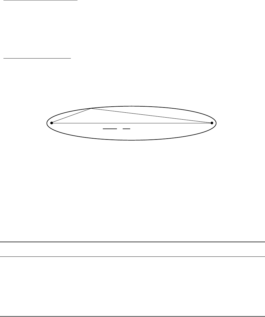
pulsAR radio Operator’s Manual
6-5
6.2.2 Earth curvature
With long links the earth curvature can prevent the two antennas from seeing each other. This is
illustrated in tables 6.2 and 6.3, which show the minimum antenna heights required, at both ends of
the link, to simply clear the earth surface at various distances. As the distance grows the effect
worsens requiring you to have access to high elevation points to deploy such links. The values in the
table used a typical atmospheric refraction factor of 4/3 (see below).
6.2.3 Fresnel Zone
The Fresnel zone is a long ellipsoid that stretches between the two antennas. The first Fresnel zone is
such that the difference between the direct path (AB) and an indirect path that touches a single point
on the border of the Fresnel zone (ACB) is half the wavelength (see figure 6.3).
AB
C
ACB - AB = λ / 2
Figure 6.3– Fresnel Zone Definition
If a significant portion of the Fresnel Zone is obstructed the receive-signal-strength at the receiving
antenna can be significantly attenuated. A rule of thumb is that you need at least 60% of the first
Fresnel Zone clear of any obstructions in order for the radio wave propagation to behave as if it is in
“free space”.
Even though at 2.4 GHz half of the wavelength is only 2.4 inches (6.2 cm), at long distances the
radius of this ellipsoid can be quite large. This is illustrated in tables 6.2 and 6.3, which show the
radius of this (60%) ellipsoid at the mid-point for various distances.
Table 6.2 – Antenna heights (meters) to clear the earth and 60% of the Fresnel Zone (2.4 GHz)
Distance (km): 5 10 20 30 40 50 60 70
Antenna height to clear
earth (meters): 0.41.5 6 1324375372
60% Fresnel Zone radius
at mid-point (meters): 7.510151821232628
Total antenna height
required (meters): 7.9122131456079100

pulsAR radio Operator’s Manual
6-6
Table 6.3 – Antenna heights (feet) to clear the earth and 60% of the Fresnel Zone (2.4 GHz)
Distance (miles) 5 10 20 30 40 50
Antenna height to clear
earth (ft) 3 12 50 113 200 313
60% Fresnel Zone radius
at mid-point (ft) 31 44 62 76 87 98
Total antenna height
required (ft) 34 56 112 189 287 412
6.2.4 Atmospheric Refraction
Under normal atmospheric conditions radio waves do not propagate in a straight line, they actually
bend slightly downward. This is due to "refraction" in the atmosphere that affects radio waves
propagating horizontally. To take this downward bending into account, we perform all the RF path
calculations using a larger value for the earth radius, such that we can then consider the radio waves
as propagating in a straight line.
In the Fresnel Zone calculator you can change the earth radius multiplying factor (the "k factor") to
take into account different atmospheric conditions. Under normal conditions the "k factor" is 4/3.
However unusual weather conditions can cause significant changes to the refraction profile. For a
high reliability link you may want to use a lower value for the k factor.
6.2.5 Clearing Obstructions
The calculator allows you to quickly determine whether you have enough clearance above a particular
obstruction in the RF path, or alternatively, how high you need to elevate your antennas to clear the
obstruction.
For each potential obstruction in the path you need to know its distance from one of your end points
and the height of the obstruction. Drawing the path in “Google Earth” is a quick way of identifying
buildings or structures that lay in the direct path and finding their distance from the end points. You
may need to use a topographic map, draw the line between the end points, and create an accurate
terrain profile. If there are buildings or trees in the path you need to determine or estimate their
height and add it to the terrain elevation at those points.
For each of these potential obstruction points, enter its distance from site 1 in the bottom left input
“spinner” of the calculator. On the right hand side the calculator displays the vertical separation
between the bottom of the Fresnel Zone and the Earth sea level (“Clearance between Earth and FZ“).
This value needs to be larger than the height of your obstruction. If it is not you can use the antenna
height spinners to increase the height of one or both antennas until that clearance exceeds the height
of your obstruction.
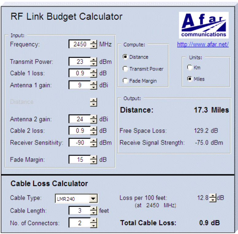
pulsAR radio Operator’s Manual
6-7
6.3 RF Link Budget Calculations
If you have radio-line-of-sight for your link (as explained in the previous section), then it is easy to
compute the receive-signal-strength at the receiving radio and from there determine if you have an
adequate “fade margin”.
You can use our free “RF Link Budget Calculator”, shown in figure 6.4, to make all the required
computations and evaluate the trade-off between antenna gains, cable losses etc. The calculator runs
on a PC and is available on the CD and at our website.
Figure 6.4 - RF Link Budget Calculator
Even though your link is bi-directional, in the calculator Site 1 is viewed as the transmitter and Site 2
as the receiver. If you configure both radios with the same transmit power the results for both
directions are identical. If you configure the transmit power of the two radios to different values you
should compute the link budget in each direction separately.

pulsAR radio Operator’s Manual
6-8
The RF link budget calculations are made a lot easier by using “deciBel” units (dB). The deciBel is a
logarithmic scale that compares a parameter value against a specific reference. The advantage of
working in dB is that you can simply add all the parameters that boost your signal and subtract the
ones that attenuate it.
The following paragraphs follow an RF signal from the transmit radio to the receive radio, explaining
the various parameters and how they apply to the pulsAR radio
Transmit Power
The RF signal starts at the output of the radio at Site 1 with a specific transmit power. In the PulsAR
radio you can configure that power from 0 to 23 dBm (the “m” in the dBm unit indicates that this
power is measured relative to 1 milliwatt).
Cable Losses
The radio is connected to the antenna through an RF coaxial cable. As the signal propagates through
this cable it is attenuated. The total attenuation (loss) depends on the frequency, cable type, cable
length and number of connectors. You can use the “Cable Loss Calculator” (at the bottom of the RF
Link Budget calculator), which includes the characteristics for several RF cable types. If your cable
is not listed you can also enter its “loss per 100 ft” (or loss per meter) at 2.4 GHz and the calculator
computes the total loss. Note that each connector along the way introduces additional attenuation,
typically around 0.25 dB per connection.
The pulsAR radio is housed in a watertight enclosure so that you can mount it in very close proximity
to the antenna. That way you can keep the RF coaxial cable very short and therefore reduce these
losses.
Antenna Gain
The transmit signal is radiated through the antenna at Site 1. The antenna focuses the radiated energy
in a specific direction or plane, boosting your signal strength in that specific direction. That boost is
measured by the “antenna gain” in dBi (the “i” in the dBi unit indicates that the antenna gain is
measured in relation to an isotropic radiating element).
Distance and Free Space Loss
Once the signal is in the air it propagates towards the receiver but suffers attenuation as it radiates
away from the transmitter. If there are no obstructions the total attenuation is called the Free-Space-
Loss (FSL). This loss is a function of the frequency, f, and the distance, d. It can be computed, in
dB, from the following expressions:
FSL = 32.4 + 20 log f + 20 log d (with f in MHz and d in km)
or
FSL = 36.6 + 20 log f + 20 log d (with f in MHz and d in miles)
The calculator computes this loss for you and displays it in the output panel. An easy rule to
remember is that the free space loss increases by 6 dB every time you double the distance.

pulsAR radio Operator’s Manual
6-9
Receive Signal Strength
The signal is much weakened when it reaches the receiving antenna. That antenna will give it a
boost, measured by the antenna gain in dBi. The signal is then attenuated as it propagates down the
RF coaxial cable that connects that antenna to the radio. The Receive Signal Strength (RSS)
parameter refers to the strength of the signal that finally arrives at the RF connector of the receiving
radio at site 2. With all the gains and losses measured in dB, this receive signal strength is computed
with the following expression:
RSS = TxPower – CableLoss1 + AntGain1 – FSL + AntGain2 – CableLoss2
The RF Link Budget calculator always computes and displays this value in the output panel.
Receive Sensitivity
The radio Receiver Sensitivity is the receive-signal-strength at the input of the radio at which point its
"Bit Error Rate (BER)" is at a specified value. Most manufacturers, including Afar, use a BER of
1x10⁻⁶ (1 bit error in one million bits) to specify the radio receiver sensitivity. However make sure
you check the specifications when comparing the sensitivity in radios from different manufacturers.
You can configure the PulsAR radio to operate at four different RF speeds. Lower speeds give you a
better receiver sensitivity. Use the appropriate value from the table below:
RF Speed (Mbps): 2.75 1.375 0.500 0.250
Receiver Sensitivity (dBm): -90 -93 -95 -98
Fade Margin
The Fade Margin is the difference between the Received Signal Strength and the radio Receiver
Sensitivity. When you deploy a link you want to have a Receive Signal Strength that is sufficiently
above the radio Receiver Sensitivity in order to survive signal fading due to a variety of factors.
These factors might include slight misalignment of the antennas, losses due to fog and rain, etc. As a
rule of thumb you should try to get at least 15 dB of fade margin in your links.
With the calculator you can select whether to compute the Distance, the Fade Margin or the Transmit
Power. All these parameters are inter-related as described above. When you select one parameter to
compute, its value in the input panel is disabled.
All the input values are controlled with “spinners”. As you change any input the calculator instantly
updates the output values. By seeing the results immediately you can quickly evaluate trade-offs
between different parameters.

pulsAR radio Operator’s Manual
A-1
APPENDIX A – Command Summary
This appendix lists all commands organized in the respective functional groups. Parameters that are
part of the radio configuration are identified by having an entry under the “Factory Configuration”
heading. When entering a command, if a parameter that is part of the radio configuration is omitted,
the value for that parameter is not modified.
For commands that are not part of the radio configuration, if a parameter is omitted, the value for that
parameter defaults to the value indicated in bold.
Configuration Management Commands
Command Parameters Values
change-password enable-configuration <string>
display-configuration source current
main
alternate
basic
factory
load-configuration source main
alternate
basic
factory
lock
save-configuration destination main
alternate
unlock enable-configuration <string>

pulsAR radio Operator’s Manual
A-2
Major Configuration Parameters
Command Parameters Values Factory
Configuration
distance-max maximum 10..160 80
units km or miles km
ethernet speed auto-10, 10hdx, 10fdx
100hdx, 100fdx, auto,
off
auto
timeout-sec 5..10000 30
multi-cast-timeout-sec 5..10000 30
node type hub, remote, root-1,
root-2, branch, leaf
remote
max-remotes 1..32 32
name (23 character string) rmt-nnnnn
network-id 0..65535 0
location (25 character string)
contact (25 character string)
rf-1-setup antenna a, b rf-1: a, rf-2: b
rf-2-setup receive-channel min..max rf-1: 12 rf-2: 25
transmit-channel min..max rf-1: 12 rf-2: 25
speed-mbps [speeds] max
power-dbm 0..max_power 18
single-node-reboot timeout-sec 15..20000 900
time-division-duplex sync-mode off, auto auto
cycle-period-ms 20, 40 20
split-outbound-percent auto, 10, 20, 30, 40,
50, 60, 70, 80, 90
auto

pulsAR radio Operator’s Manual
A-3
Internet Protocol (IP) Management Commands
Command Parameters Values Factory
Configuration
ip-configuration address ip address
netmask ip address
gateway ip address
dhcp-client on, off off
ping destination ip address
count 0..500 (def 4)
size-bytes 32..1400
snmp manager ip address
community ASCII string (9 max)
access g, gs, gt, gst
authentication-traps 0, 1
delete 1..4
udp-configuration console on, off off
vital-port-1 1..0xFFFF 0
vital-port-2 1..0xFFFF 0
command-port 1..0xFFFF 422
max-response-bytes 500..1466 512
socket-mode 1, 2 1
peer-address ip address
peer-command-port 1..0xFFFF 0

pulsAR radio Operator’s Manual
A-4
Installation and Link Monitoring Commands
Command Parameters Values Factory
Configuration
antenna-alignment-aid mode off,
a-antenna, b-antenna
off
monitor-flow
monitor-link node 1,4,5,6…
clear 0, 1
monitor-roaming
show-tables table status, ethernet,
econsole, links,
tree, radios, ip-stack
format count
times
spectrum-analysis antenna a, b
display graph
table
dwell-time-ms 1…1000 (def: 20)
time-analysis channel 0..50
antenna a, b
display graph
table
dwell-time-ms 1, 2, 5, 10, 20, 50,
100, 200, 500

pulsAR radio Operator’s Manual
A-5
File Utilities
Command Parameters Values
console-speed-bps baud-rate-bps 9600, 19200, 38400
57600, 115200
copy-file source filename
destination filename
delete-file filename filename
directory format short
full
download-file source path/filename
destination path/filename
method binary
inline
run-file filename filename
set-default-program filename filename
Event Logging Commands
Command Parameters Values Factory
Configuration
clear-log region all-events
reboot-reasons
display-log region end
tail
beginning
all-events
reboot-reasons
length 1..500 (def 10)
id 0…200
min-level 0…7 (def: 0)
max-level 0…7 (def: 7)
max-event save 0..7 5
print 0..7 3

pulsAR radio Operator’s Manual
A-6
Miscellaneous Commands
Command Parameters Values Factory
Configuration
date date dd-mmm-yyyy
time hh:mm:ss
zone offset or code GMT
help command
history
license key <35 character string>
logout
reboot
time time hh:mm:ss
date dd-mmm-yyyy
zone offset or code GMT
version

pulsAR radio Operator’s Manual
B-1
APPENDIX B – Specifications
RF Specifications AR-9010E AR-9027E AR-24010E AR-24027E AR-240110E
RF Frequency Band (MHz) 902 to 928 902 to 928 2400 to 2483 2400 to 2483 2400 to 2483
Signal Bandwidth (-20 dBc) 1.6 MHz 4.6 MHz 1.6 MHz 4.6 MHz 17 MHz
RF Channels (non-overlap): 13 4 35 11 3
Transmitter Output Power: 0 to 27 dBm 0 to 27 dBm 0 to 27 dBm 0 to 27 dBm 0 to 27 dBm
(dBm) (kbps) (dBm) (kbps) (dBm) (kbps) (dBm) (kbps) (dBm) (kbps)
Receiver Sensitivity
(10-6 BER)
and Data Rates
-103 @
-100 @
-98 @
-95 @
100
200
550
1100
-100 @
-97 @
-95 @
-92 @
250
500
1375
2750
-100 @
-97 @
-95 @
-92 @
100
200
550
1100
-98 @
-95 @
-93 @
-90 @
250
500
1375
2750
-94 @
-91 @
-89 @
-86 @
1000
2000
5500
11000
Maximum Receive Signal -30 dBm (to stay in receiver linear region)
+20 dBm (to avoid damage)
Modulation Type direct sequence spread spectrum
Ethernet Port
Speed 10/100 BaseT, full/half duplex, auto-negotiate
Connector 8 pin circular (Lumberg 0321-08) - RJ45 at the power inserter
Networked Operation
Network topologies Point-to-point, point-to-multipoint, Mesh/Tree, Linear Network, Roaming
Management Telnet, SNMP (MIB2), or Econsole reach any node over wireless
Security Optional 3-DES or AES encryption, 32 bit network ID / password.
Console / Diagnostic Port
Interface RS-232/V.24, asynchronous 9600 to 115 kbaud
Connector 3 pin circular (Lumberg 0321-03) - cable adapter to DB9 available
Power
Input Voltage DC: Power over Ethernet (IEEE 802.3af) or +10 to +58 VDC
AC: 110 to 220 VAC (with external power inserter)
Power Consumption Rx: 2.8 W Sleep: 0.7 W
Tx: < 4.0 W
Rx: 2.8 W Sleep: 0.7 W
Tx: < 6.3 W
Transient Max. Peak Power 1500W (with 10/1000 us waveform)
Transient Max. Peak Current 35 A (with 10/1000 us waveform as defined by R.E.A.)
Environmental
Temperature -40 to +70 deg C (-40 to +158 deg F)
Max. Humidity Up to 95% non-condensing
Mechanical
Dimensions 4.72" wide x 8.66” high x 2.20” deep (120mm W x 220 H x 56 D)
Weight 3.4 lbs. (1.5 kg).
pulsAR radio Operator’s Manual
B-2

pulsAR radio Operator’s Manual
C-1
APPENDIX C – Channel Frequencies
900 MHz Models:
The center frequency of each channel can be determined by the following expression:
Freq(MHz) = 900 + Channel_number
The table below shows the frequencies for all channels that fall in the ISM band.
Chan
Freq
(MHz) Chan
Freq
(MHz) Chan
Freq
(MHz)
1 11 911 21 921
2 12 912 22 922
3 903 13 913 23 923
4 904 14 914 24 924
5 905 15 915 25 925
6 906 16 916 26 926
7 907 17 917 27 927
8 908 18 918 28
9 909 19 919 29
10 910 20 920 30
Model
Number of
Non-Overlapping
Channels
Suggested Channel Allocation
Frequency
Separation
(MHz)
13 3,5, 7, 9, 11, 13, 15, 17, 19, 21, 23, 25,27 2.0
7 6, 9, 12, 15, 18, 21, 25 3.0
6 5, 9, 13, 17, 21, 25 4.0
AR9010E
5 5, 10, 15, 20, 25 5.0
AR9027E 4 6, 12, 18, 25 6.0

pulsAR radio Operator’s Manual
C-2
2.4 GHz Models:
The center frequency of each channel can be determined by the following expression:
Freq(MHz) = 2400 + 2 x Channel_number
The table below shows the frequencies for all channels that fall in the ISM band.
Chan
Freq
(GHz) Chan
Freq
(GHz) Chan
Freq
(GHz) Chan
Freq
(GHz)
1 2.402 11 2.422 21 2.442 31 2.462
2 2.404 12 2.424 22 2.444 32 2.464
3 2.406 13 2.426 23 2.446 33 2.466
4 2.408 14 2.428 24 2.448 34 2.468
5 2.410 15 2.430 25 2.450 35 2.470
6 2.412 16 2.432 26 2.452 36 2.472
7 2.414 17 2.434 27 2.454 37 2.474
8 2.416 18 2.436 28 2.456 38 2.476
9 2.418 19 2.438 29 2.458 39 2.478
10 2.420 20 2.440 30 2.460 40 2.480
Model
Number of
Non-Overlapping
Channels
Suggested Channel Allocation
Frequency
Separation
(MHz)
12 3, 6, 9, 12, 15, 18, 21, 24, 27, 30, 33, 36 6.0
9 4, 8, 12, 16, 20, 24, 28, 32, 36 8.0
7 5, 10, 15, 20, 25, 30, 35 10.0
6 5, 11, 17, 23, 29, 35 12
AR24010E
or
AR24027E
4 8, 16, 24, 32 16
AR24110E 3 9, 20, 31 22

pulsAR radio Operator’s Manual
D-1
APPENDIX D – Ethernet Console Program
Short description
The ethernet console program was developed in order to accommodate the remote configuration of a
radio, i.e. the configuration in cases where the physical access to the radio is not feasible, or it is
cumbersome. The software consists of two parts: the client and the server. The client runs on the
administrator's PC, while the server runs on the radio.
The communication is done via a TCP-like protocol. There is an acknowledgment for every packet
that is sent, as well as a retransmission mechanism when a packet gets lost.
Each radio allows multiple sessions, i.e. more than one client can be connected concurrently to the
same server (radio). Nevertheless, for performance reasons, it is not recommended to have more
concurrent sessions than they are really needed, and definitely not more than the maximum number
which currently is 4.
System requirements
• Win95, Win98, Windows ME, WinNT, Win2000, WinXP
• NetBIOS installed
• WinPCap installed
Note: With regard to Windows NT platform, the code has been tested with versions 4.0, or newer. There is also
a Linux beta version
Installation for Windows
In order to install the WinPCap library, if not already installed, just click on the WinPCap.exe.
Support and updates for this library can be found at http://netgroup-serv.polito.it/winpcap/. It is
strongly suggested to uninstall older versions of the library and reboot the machine before installing
the new one. NetBIOS is a software component that comes by default with all Windows system, so
you don't have to install it. To start the Econsole, simply open a MS-DOS window and type econ. For
available command line arguments, please read the "input arguments" section.
Included files
• win_readme.doc The file that you are reading
• econ.exe The EConsole client
• WinPCap The Windows installer for the WinPCap library
• input_script.txt A sample input script file, that contains a list of radio commands.
Input arguments
You can provide the following arguments in the command line, even though none of them is required.

pulsAR radio Operator’s Manual
E-2
Input file
There are two sources for the input commands: the keyboard, or a text file. The second option is
useful when you are running the same set of commands periodically, so you want to avoid retyping
them every time you want to execute them. If there is an input file in the command line, then the
keyboard will be deactivated and only the function keys will be available. If the specified file cannot
be found, the application will be terminated.
example:
C: > econ -i input.txt
Sample input file:
help
# this is a comment - note that the character # must appear as the fist character
time
date
# the following is a local command specifying a delay in seconds
. delay 10
time
. delay 1.5
version
logout
As you probably noticed from the above file, all the lines are interpreted as radio command, unless:
a) They start with the character ‘#’ which implies a comment
b) They start with the character ‘.’ which implies a local command. Currently there is only one local
command, namely the delay < time in secs>
Important note: All the input scripts should end with the logout command. Since all the commands are terminated with the
new line character, there must be one command per line and after the final logout command you must have an extra empty
line.
Output file
When you want to capture the output of a session into a text file, you can pass the filename as an
argument. If the file does not exist it will be created, otherwise it will be overwritten.
example:
>econ -o output.txt
Radio MAC address
If you are interested in a specific radio, you can pass its MAC address and let the client ignore any
response from other radios. That's very handy when you are always getting connected to the same
radio and you want to avoid the manual selection of a preferred one. Very useful also in case you are
using scripts for fully automated procedures.
example:
>econ -r 00:78:24:22:BA:4F
Radio Serial Number

pulsAR radio Operator’s Manual
D-3
The same functionality as above (see Radio MAC address) can be achieved by providing the radio
serial number, instead of the radio physical address. Note that you should not include the initial UC
characters of the serial number (i.e. type 11078 instead of UC11078)
example:
>econ -r 11787
Local Physical Address
Even though econsole identifies the PC local physical address automatically, there are some cases in
which the user wants to specify the local address on his/her own. These cases usually arise when there
are multiple NIC cards with the same names under WinNT operating system. In such case, the econ
might pick up the wrong MAC address, and therefore the user should supply manually the physical
address as a command line argument.
example:
>econ -m 00:78:24:22:BA:4F
Inverse Screen Colors
You can change the default settings (white texture on black background) by providing the -b option,
which will change the settings to black characters on white background.
example:
>econ -b
Change the console window size
Currently you can specify two values, either 25 or 50. These values indicate the number of lines of
the MS-DOS window.
example:
>econ -l 50
Help
Function keys, including F1, are activated after you get connected to a radio. If you want to get help
from the command line, you can use the -h argument.
example:
>econ -h
Syntax:
econ <argument list>
argument list = argument list | argument | {}
argument = -o outputfile | -i inputfile | -r MAC address
Examples
Let's say you want to read a list of commands from the text file called in.txt, and capture the output to
a text file called out.txt. You are also interested only in a specific radio with MAC address equal to
00:78:24:22:BA:4F. In that case, you will start the EConsole with the following arguments (the
arguments order is irrelevent):
>econ -i in.txt -o out.txt -r 00:78:24:22:BA:4F or

pulsAR radio Operator’s Manual
E-4
If you are reading from the keyboard, and you are simply interested in capturing the output of the
session, use the following syntax:
>econ -o out.txt
Since no input file was specified, it is assumed that the keyboard will be used for input, and ALL
radios will participate in the discovery process.
Function Keys
Currently there are 6 different function keys.
F1 - Online help - gives a short description of the other function keys and the input arguments
F2 - Active/deactivate diagnostic messages. Initially diagnostic messages are not shown, therefore
if you want to see them you should press F2. Diagnostic messages include warnings, and
retransmission info in order to get an idea of the connection's speed/integrity. Error messages
are always shown.
F3 - Terminates the current session and closes the application.
F4 - Close the session with the current radio and display the results of the initial discovery phase
to allow the user to connect to a new radio.
F5 - Reverse/Restore screen settings. Initially the screen displays white letters on black
background, but you can reverse it to black letters on a white background.
F6 - Increases the console window buffer. This introduces a side bar which enables the user to
scroll up and down. Available in Windows NT Only.
Troubleshooting & Updates
Common problems
1. Failed to open adapter
This usually happens when you haven't installed properly the WinPCap library, or you have
and older version of it. Please visit http://netgroup-serv.polito.it/winpcap/ to get the latest
version. You should also make sure that your Ethernet adapters are working properly.
2. Cannot find radio(s) even though they are running properly
Make sure that:
• The ethernet cables are OK
• You are getting connected to the right network segment (i.e. try all ethernet adapters)
• You are using the right MAC address. The system tries to identify the adapter physical
address through some NetBIOS calls in the Win9X case, or some NDIS queries in the
WinNT/Win2000 case. If NetBIOS is not installed, the econ will probably use the wrong
local host MAC address. Also if there are more than one Ethernet adapter installed with
the same name, this might cause problem in the WinNT case.
Resolution: Use the command line argument to specify the correct physical local address.
You can see all the local physical address by executing the ipconfig -all command. Example:
>econ -m 00:78:24:22:BA:4F
3. Find a radio but not getting connected
Check if the maximum number of sessions has been reached. The maximum number of
sessions on the server side is limited to four, therefore you should NOT connect to the same
radio multiple times if not absolutely necessary. When the number of sessions reaches the
limit the radio will ignore any new discovery messages.
pulsAR radio Operator’s Manual
D-5
Another reason might be a unreliable RF link causing a high packet loss. Since during the
discovery phase there isn't any retransmission mechanism, it is quite possible that you
managed to "see" the radio, but you weren't able to connect to it, because the connection
request packet was lost. In such case, try to connect again.
4. High drop rate - screen freezes momentarily - connection times out
There are two possible causes.
1. The link between the client (PC) and the server (radio) is very weak. If the packet drop rate is
more than 20%, then the connection is problematic.
2. There are multiple sessions opened on the same server. With many concurrent sessions the
server response may be noticeably slower. Always close the session gracefully by executing
the logout radio command, and not by closing the MS-DOS console. If the logout command
is not issued the session at the server will remain open for an additional 15 minutes. Use the
list long command to find out the number of open sessions.
5. If I leave the client inactive for half an hour, and try to type a new command, I get an unable to
transfer packet message or I get a "session timeout - application will be closed" message.
An open session times out after 15 minutes of inactivity on the server side, and 30 minutes on
the client side.
Report a bug & Updates
Please visit http://www.afar.net/ for more info.
Acknowledgments
The WinPCap library was obtained from “Politecnico di Torino” and the code is distributed in binary
form as part of the Econsole. The following copyright notice applies to that library.
/*
* Copyright (c) 1999, 2000
* Politecnico di Torino. All rights reserved.
*
* Redistribution and use in source and binary forms, with or without
* modification, are permitted provided that: (1) source code distributions
* retain the above copyright notice and this paragraph in its entirety, (2)
* distributions including binary code include the above copyright notice and
* this paragraph in its entirety in the documentation or other materials
* provided with the distribution, and (3) all advertising materials mentioning
* features or use of this software display the following acknowledgement:
* ``This product includes software developed by the Politecnico
* di Torino, and its contributors.'' Neither the name of
* the University nor the names of its contributors may be used to endorse
* or promote products derived from this software without specific prior
* written permission.
* THIS SOFTWARE IS PROVIDED ``AS IS'' AND WITHOUT ANY EXPRESS OR IMPLIED
* WARRANTIES, INCLUDING, WITHOUT LIMITATION, THE IMPLIED WARRANTIES OF
* MERCHANTABILITY AND FITNESS FOR A PARTICULAR PURPOSE.
*/

pulsAR radio Operator’s Manual
E-1
APPENDIX E – Cable Diagrams
The next two pages show the assembly drawings for the cables used to connect the Radio to a Power
Inserter Unit (CAT5), and a Console cable for connection to a standard computer terminal used for
Radio configuration and monitoring.
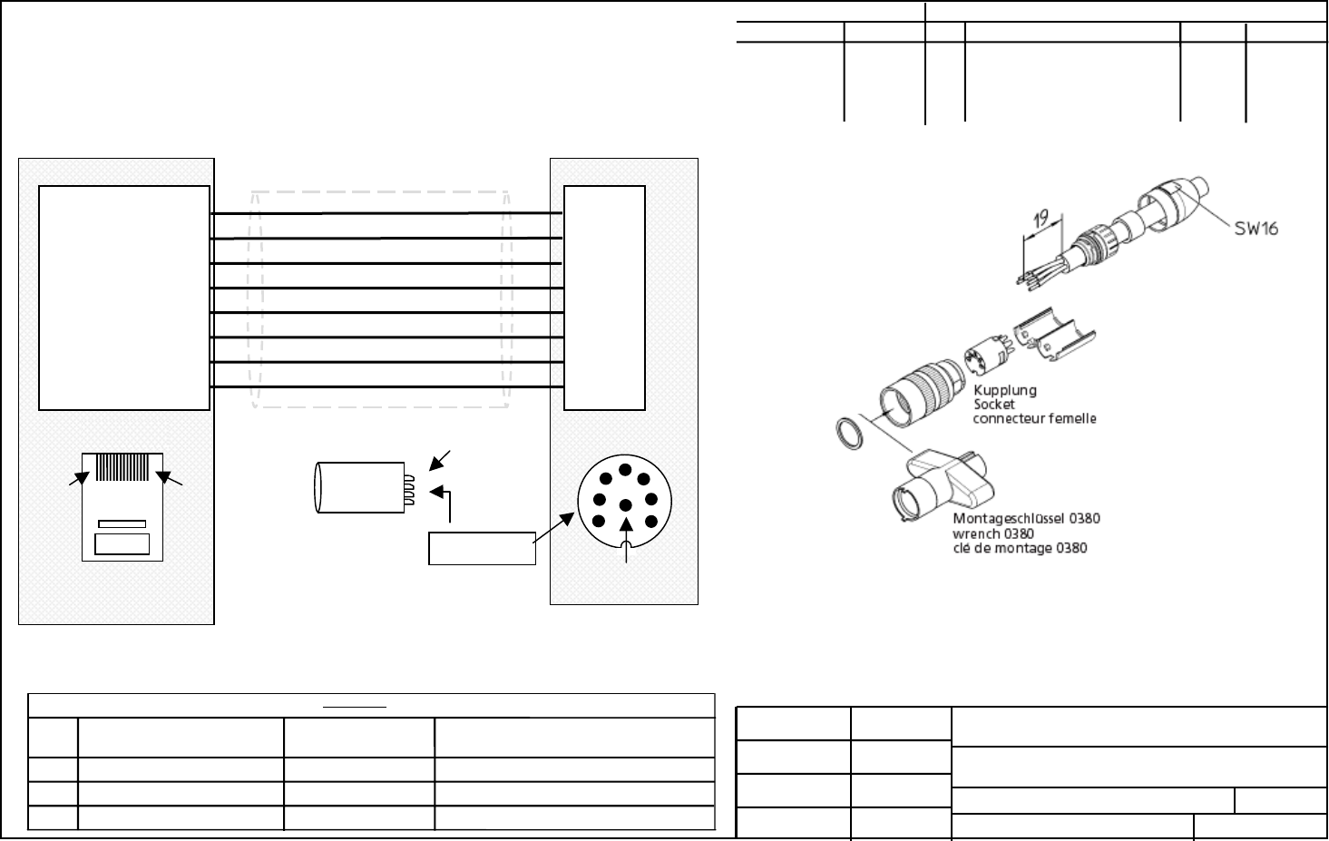
pulsAR radio Operator’s Manual
E-3
SHEET
REDRAWING
TITL
DRAWN
CHECKED
DAT
DAT
A
PPROVE DAT
A
PPROVE DAT SCAL
CAT5 ETHERNET & POWER
CBL-0503-
A
1NON
J. 9/15/0
APPLICATIO REVISIO
NEXT USED RE DESCRIPTIO DAT
A
PPROV
A
8 Pin Field Connector, FemaleLumberg USA
0321 08 or 0322 08 (fig. A)3
MATERIAL
Plug Connector, 8 Cond., RJ45-type
A
llen Tel
A
T8X8SC-2224
2
Cable, CAT5, Outdoor, Solid Cond.CommScope
5EXH04P24-BK-R-CMS-PV1
DESCRIPTION
MANUFACTURER
PART NO.
ITEM
Fig. A Five pin connector is shown. Use same process for 8 pin.
NOTES:
1. Use proper crimp tool for Item #2 connection
2. Remove cable filler gel from conductors before inserting into Item #2.
3. Insure that all eight conductors reach to end of interior channel before crimping Item #2.
4. Add label near item #2 “Afar Communications / CBL-0503-XXX” where XXX is cable len
g
th in
A
FAR Communications
,
1
RJ 45
ITEM ITEM
WHT
/
OR
OR
WHT
/
GR
BLU
WHT
/
BLU
GR
WHT
/
BR
BR
ITEM
W
/
BL
W
/
GR
GR
OR
W
/
BR
BL
BR
W
/
OR BR
NO TAB
1
7
2
3
4
5
6
W
/
OR
8
Solder
REA
R
Cable Length, in feet, specified in part number:
Exam
p
le: CBL-0503-050 for a 50 feet cable
5
A
J.BInitial Release 09
/
15
/
03
RADIO_ETH_TX+ 1
RADIO_ETH_TX- 2
RADIO_ETH_RX+ 3
VDC 4
VDC 5
RADIO_ETH_RX- 6
GND 7
GND 8
1
7
2
3
5
4
8
6
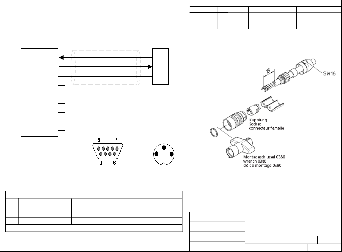
pulsAR radio Operator’s Manual
E-4
SHEET
RE
DRAWING NO
TITL
DRAWN
CHECKED BY
DAT
DAT
A
PPROVE DAT
A
PPROVE DAT SCALE
3 Pin Console Cable
CBL-0403-XXX
A
1
NONE
J. Becker 9-16-2003
APPLICATIO REVISION
NEXT USED RE DESCRIPTIO DAT
A
PPROV
A
3 Pin Field Connector, Female
MATERIAL
2
Serial Direct Cable Db9, F/F 6’.**
Belkin
F3B207061
DESCRIPTION
MANUFACTURER
PART NO.
ITEM
1
2
3
Contact
arrangements
shown from face of
DB9 connector
ITEM #1
DB-9 ITEM #2
Contact
arrangements
shown from rear of
0321 03 connector
** 6’ cable cut in ½ will make two cables.
0321 03 or 0322 03 (fig. A) Lumberg USA
ITEM #1
DB-9 ITEM #2
A
FAR Communications,
Fig. A Five pin connector is shown. Use same process for 3 pin.
1
2
3
2
3
5
1
4
6
7
8
9
RS232_RX
RS232_TX
GND
A
Initial Release 09/16/03 J.B

APPENDIX F – Quick Setup Examples
The next pages show examples on how to configure the pulsAR radios to deploy various topologies
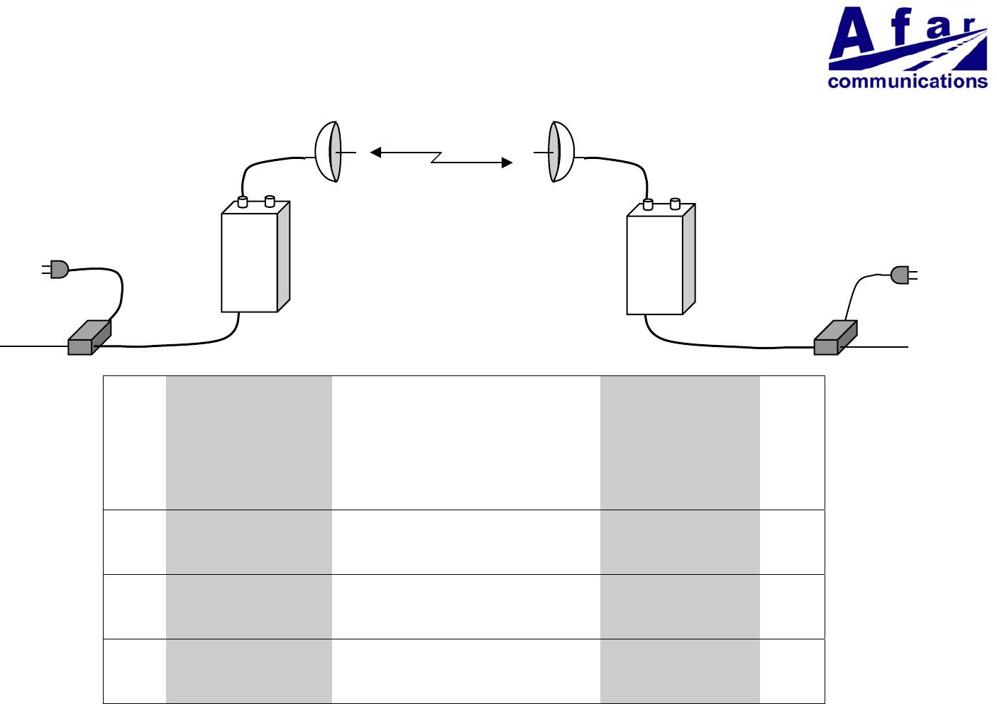
Wireless Point to Point Bridge
Quick Setup Example
Minimal Configuration
>load factory >load factory
>node hub >save
>node max-children=1
>save
Changing RF Channels (optional)
>rf1 rec=18 tr=18 >rf1rec=18
Changing Tx Power (optional)
>rf1 power=23 >rf1 power=23
Checking Link Operation
>show radios >show radios
>monitor-link >monitor-link
AC Power
CAT5
Coax
LAN
AC Power
CAT5
Coa
x
LAN
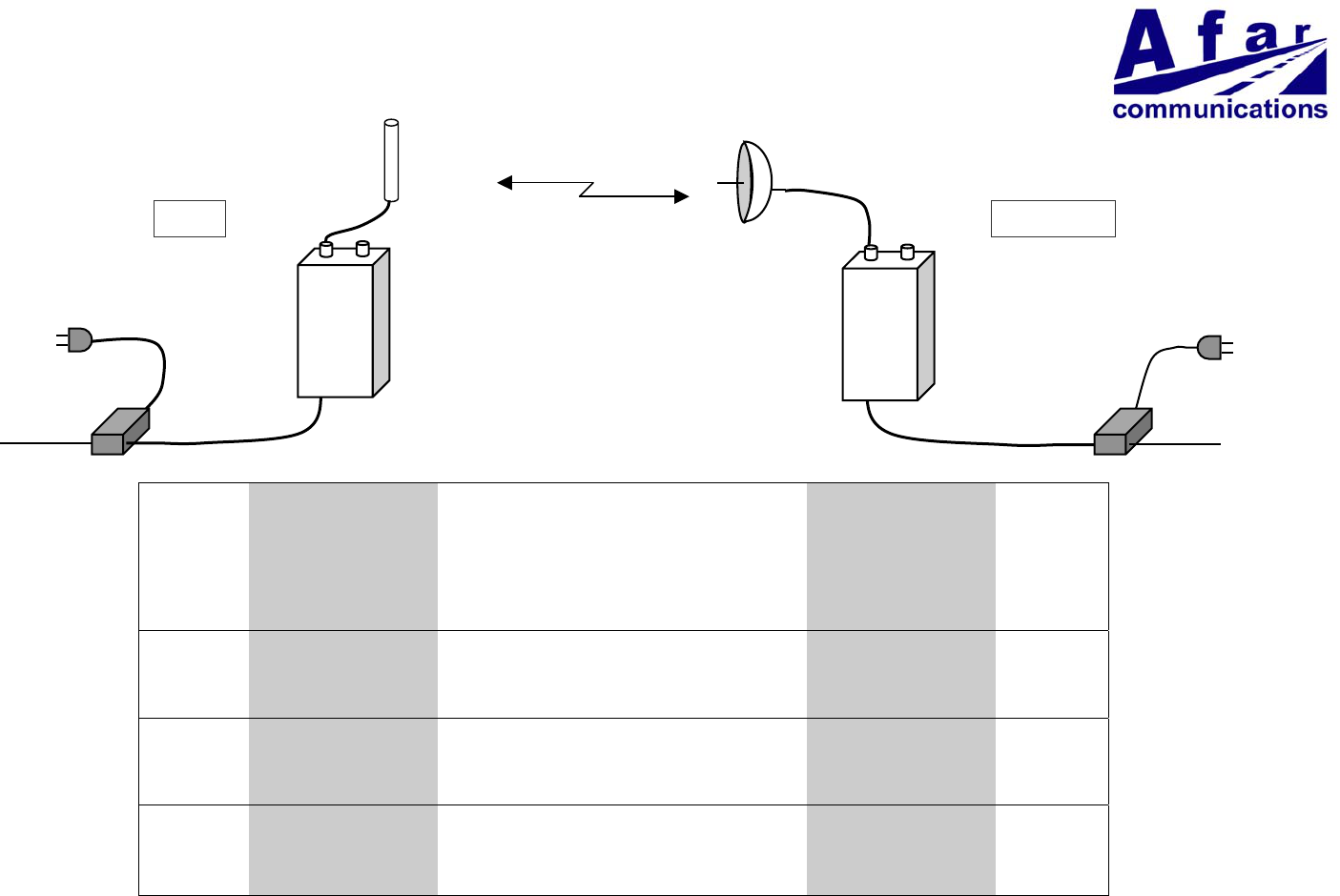
Wireless Point to Multi-Point Bridge
Quick Setup Example
Minimal Configuration
>load factory >load factory
>node hub >save
>save
Changing RF Channels (optional)
>rf1 rec=18 tr=18 >rf1 rec=18
Changing Tx Power (optional)
>rf1 power=23 >rf1 power=23
Verifying Network Operation
>show radios
AC Power
CAT5
Omni
LAN
AC Power
CAT5
Coa
x
LAN
HUB REMOTES
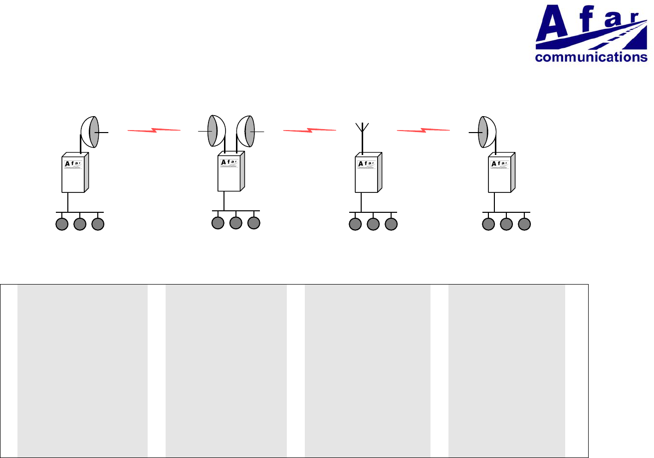
Wireless Linear Network
Quick Setup Example
Leftmost node Middle
(2 antennas)
Middle
(single antenna)
Rightmost
>load factory >load factory >load factory >load factory
>node type=root-1 >node type=branch >node type=branch >node type=leaf
>node max-children=1 >node max-children=1 >node max-children=1
>rf1 ant=b tr=6 rec=6 >rf1 ant=a rec=6 >rf1 ant=a rec=12 >rf1 ant=a rec=18
>rf2 ant=b tr=12 rec=12 >rf2 ant=a tr=18 rec=18
>save >save >save >save
LAN LAN LANLAN
Channel 6 Channel 12 Channel 18
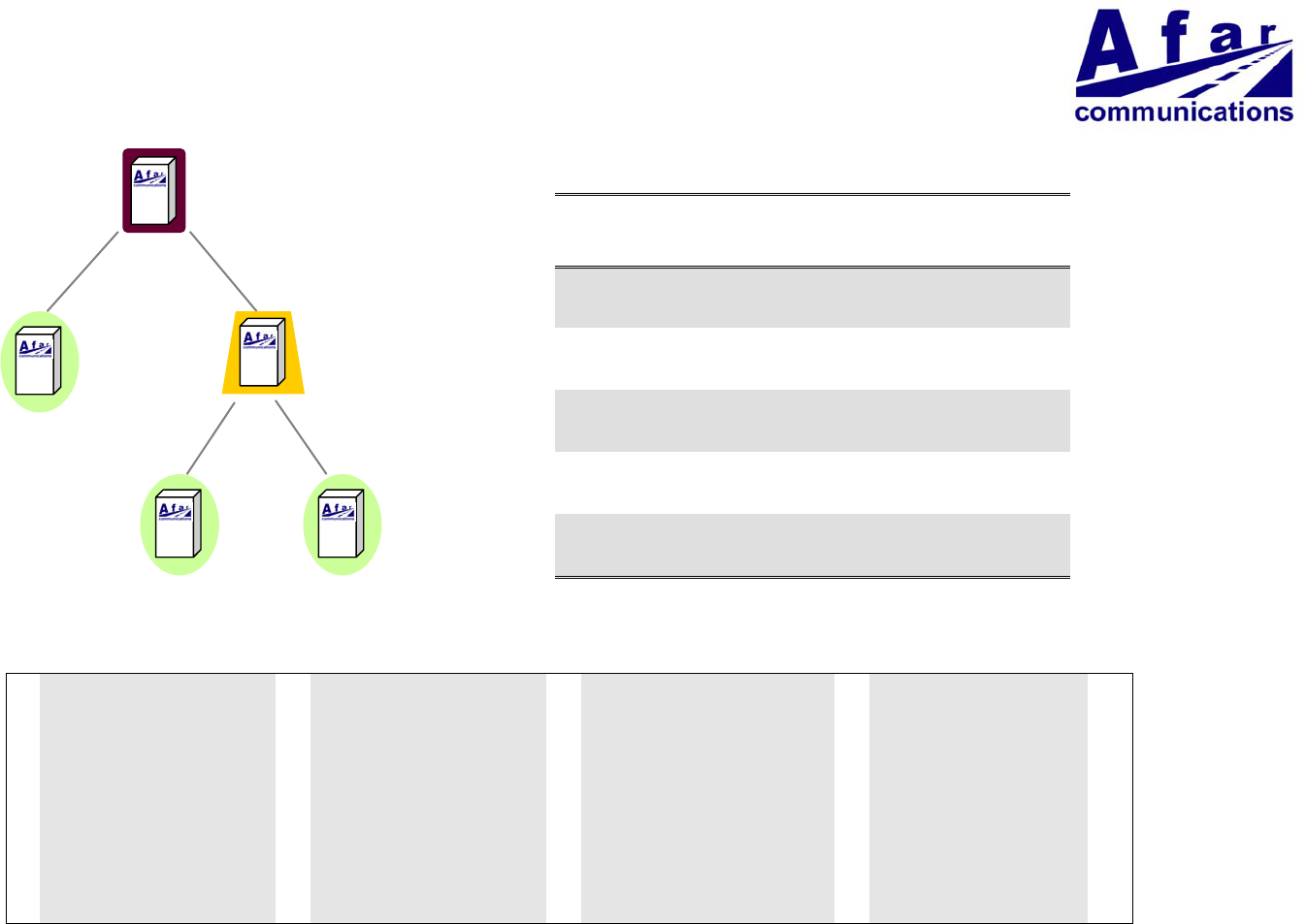
Wireless Tree Network
Quick Setup Example
Antennas
A B
1 – root Omni not used
2 – leaf Directional
(point to 1)
not used
3 – branch Directional
(point to 1)
Omni
4 – leaf Directional
(point to 3)
not used
5 – leaf Directional
(point to 3)
not used
Minimum Configuration
1 2 3 4 and 5
>load factory >load factory >load factory >load factory
>node type=root-1 >node type=leaf >node type=branch >node type=leaf
>rf1 tr=12 rec=12 (1) >rf1 rec=12 (1) >rf1 rec=12 (1) >rf1 rec=25
>rf2 tr=25 rec=25 (1)
>save >save >save >save
Note 1: Channel 12 and 25 are the defaults for rf1 and rf2 configurations. These commands are not necessary if you plan to use those defaults.
At any node use command “>show tree” to view the complete network and key statistics for each link
1
23
45
Channel 12
Channel 25
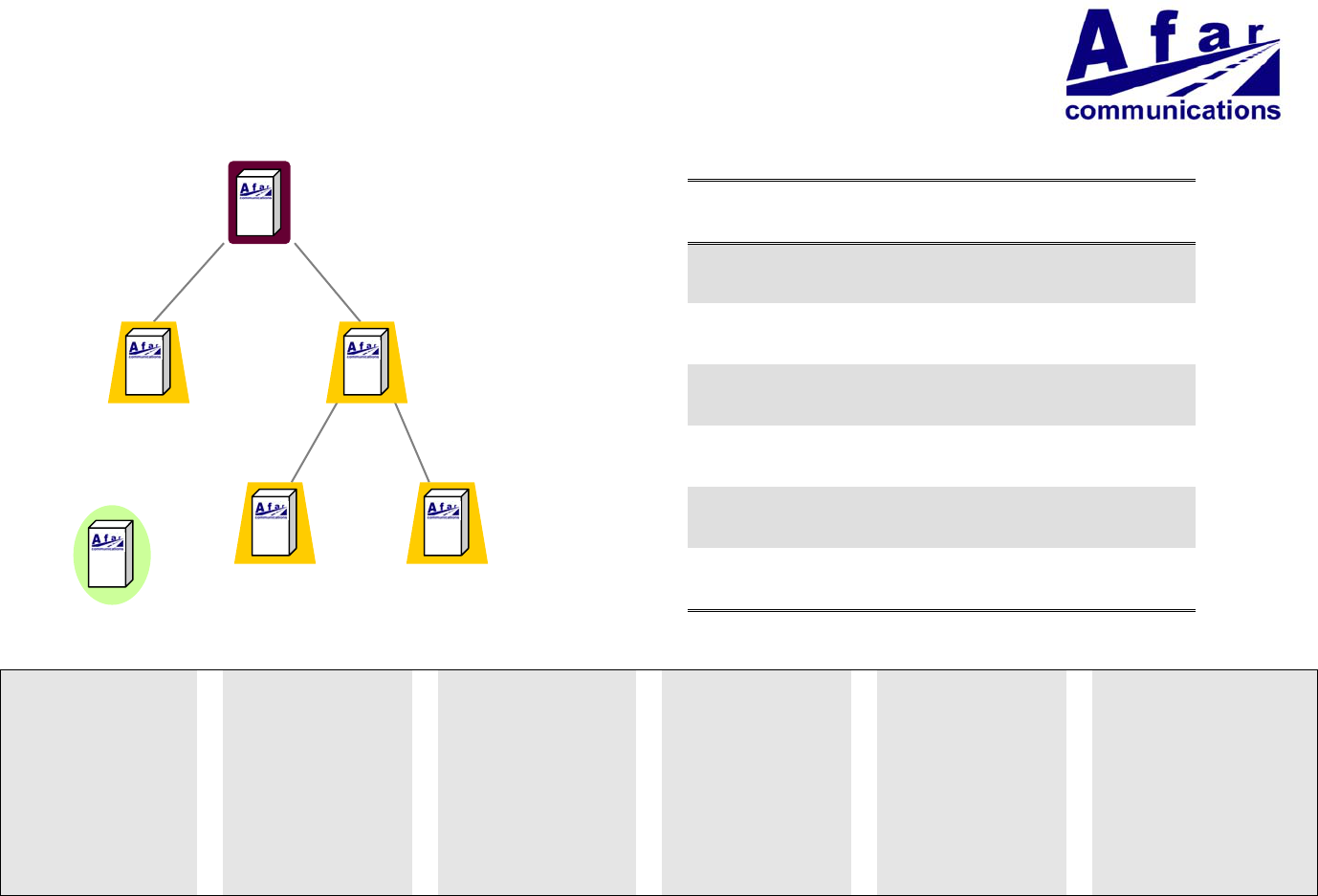
Wireless Tree Network and Roaming
Quick Setup Example
Antennas
A B
1 – root Omni not used
2 – branch Directional
(point to 1)
Omni
3 – branch Directional
(point to 1)
Omni
4 – branch Directional
(point to 3)
Omni
5 – branch Directional
(point to 3)
Omni
6 - leaf Omni not used
Minimum Configuration
1 2 3 4 5 6
>load factory >load factory >load factory >load factory >load factory >load factory
>node type=root-1 >node type=branch >node type=branch >node type=branch >node type=branch >node type=leaf
>rf1 tr=12 rec=12 (1) >rf1 rec=12 (1) >rf1 rec=12 (1) >rf1 rec=25 >rf1 rec=25 >rf1 rec=6,12,18,25,32
>rf2 tr=6 rec=6 >rf2 tr=25 rec=25 (1) >rf2 tr=18 rec=18 >rf2 tr=32 rec=32
>save >save >save >save >save >save
Note 1: Channel 12 and 25 are the defaults for rf1 and rf2 configurations. These commands are not necessary if you plan to use those defaults.
At any node use command “>show tree” to view the complete network and key statistics for each link.
At the mobile use the command “>monitor-roam” to see the signal strengths and verify the roaming operation as the signal strengths vary.
1
23
45
6
(mobile)
Ch 12
Ch 25
Ch 32Ch 18
Ch 6