AFAR Communications 24027 Wireless Ethernet Bridge User Manual 373526
AFAR Communications, Inc Wireless Ethernet Bridge 373526
UserManual.wiki
>
AFAR Communications
>
24027 User Manual
>
User Manual
Contents
1.
User Manual
2.
Additional User Manual
User Manual
Navigation menu
Upload a User Manual
Namespaces
Wiki Guide
HTML
PDF
Info
Views
User Manual
Discussion / Help
Navigation

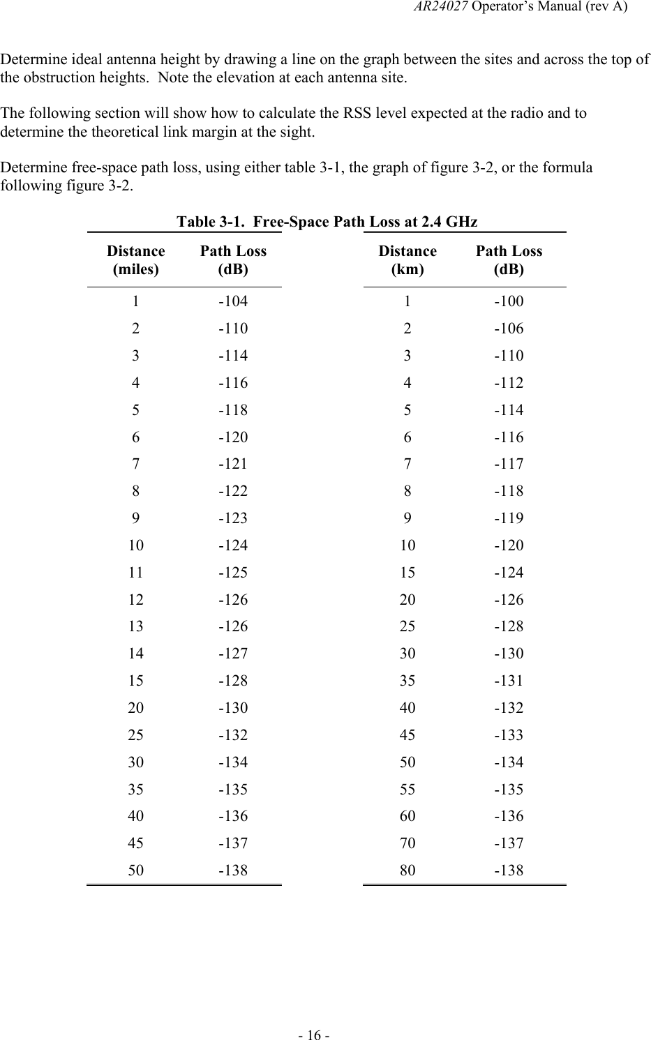
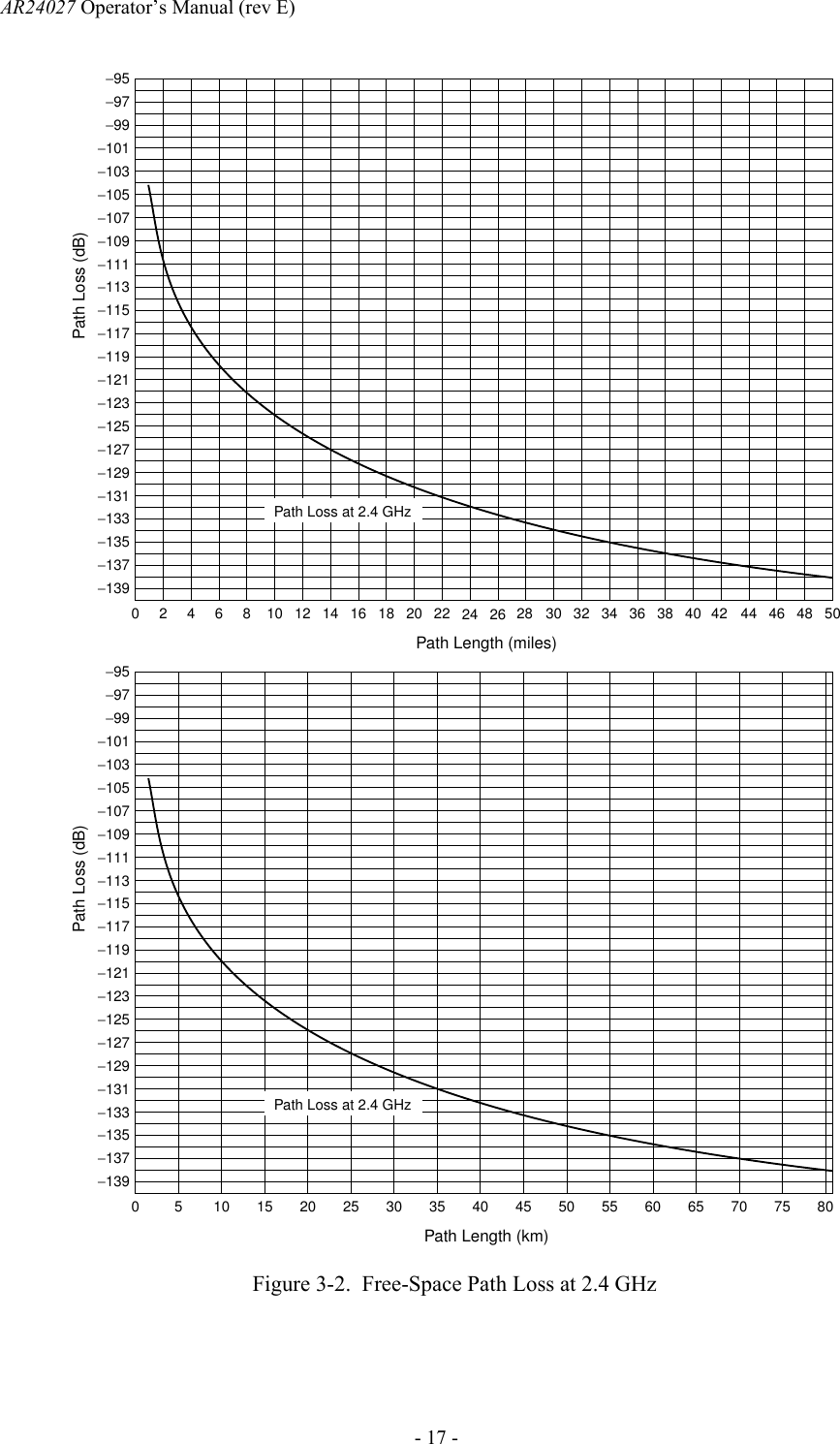
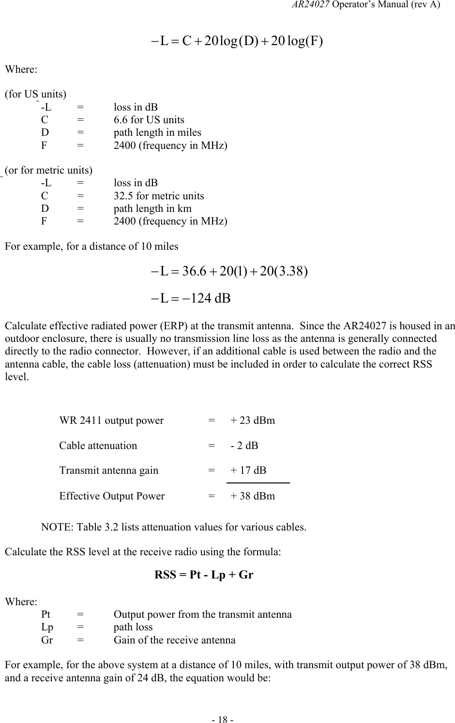
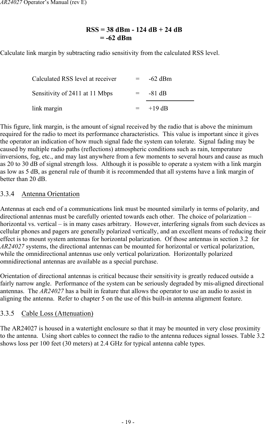
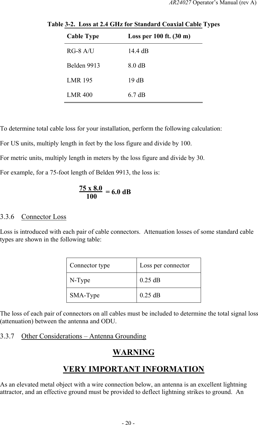

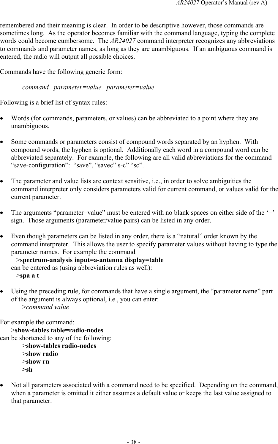

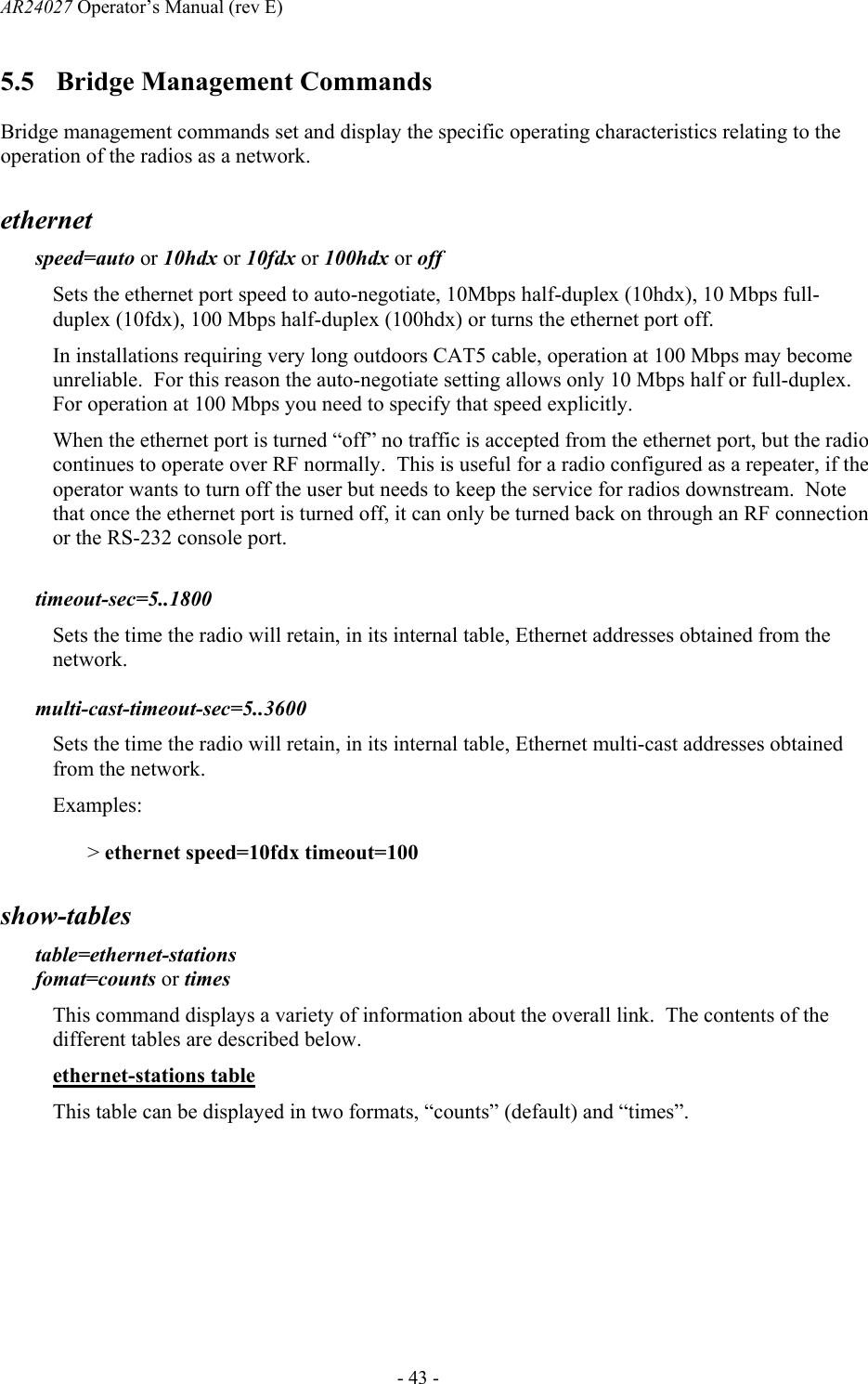

![AR24027 Operator’s Manual (rev A) - 52 - zone=zone-code or offset Sets the time zone to be used by the radio to translate the NTP time to local time. It can be specified by an offset from GMT (-0800 or +0200 for example), or as a “zone-code”. The valid “zone-codes” and the respective offsets are shown below: Zone zone code offset Pacific Standard Time PST -0800 Pacific Daylight Time PDT -0700 Mountain Standard Time MST -0700 Mountain Daylight Time MDT -0600 Central Standard Time CST -0600 Central Daylight Time CDT -0500 Eastern Standard Time EST -0500 Eastern Daylight Time EDT -0400 Greenwich Mean Time GMT 0000 help [command-name] If no command is specified, displays the complete list of commands. If a command is specified it displays the valid parameter and corresponding values for that specific command. Examples: >help monitor-link history Displays the previous commands entered. license key=< ASCII string> The “license” command is used to turn ON or OFF a set of optional features or capabilities. The key is a 35-character string combination of ASCII letters, numbers, and hyphens. The key must be input with the syntax as shown in the example below, including hyphens, for the radio to accept it. The characters can be input as upper or lower case. After entering the key you must reboot the radio for the feature, enabled by the key, to take effect. Each key is unique for a particular radio serial number and capability, i.e. a key generated to turn ON a capability on one serial number will not work on another radio. Example: >license key=02EL1-ZGZ42-G0000-00C54-81WAJ-C9BEK](https://usermanual.wiki/AFAR-Communications/24027.User-Manual/User-Guide-373526-Page-59.png)