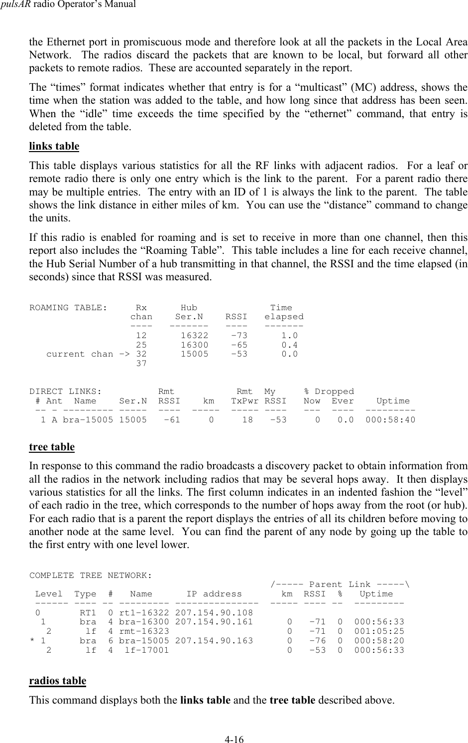
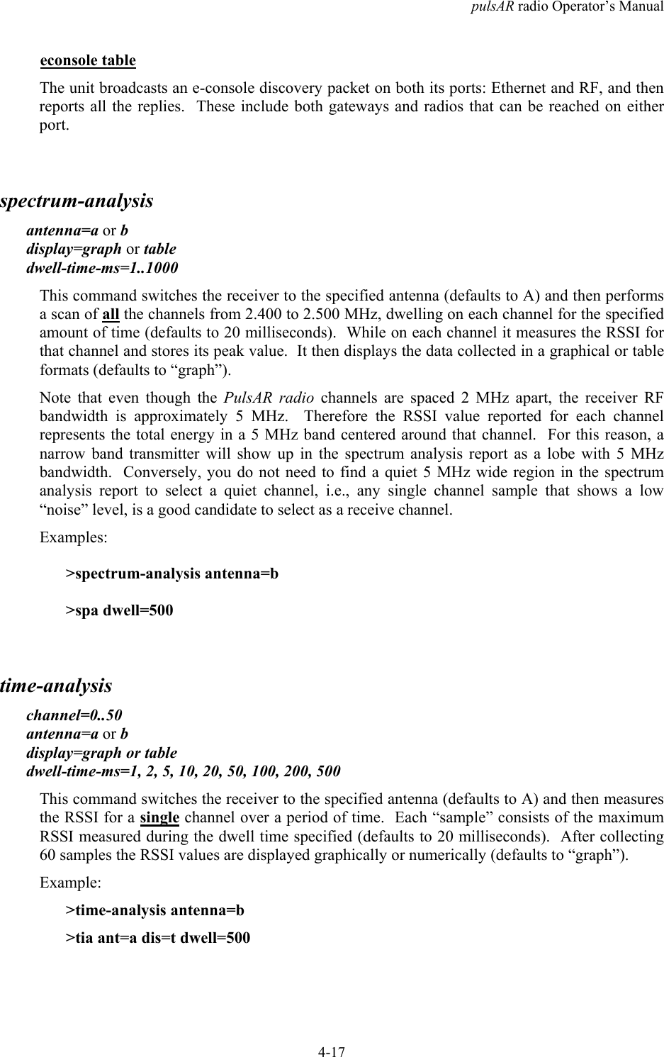
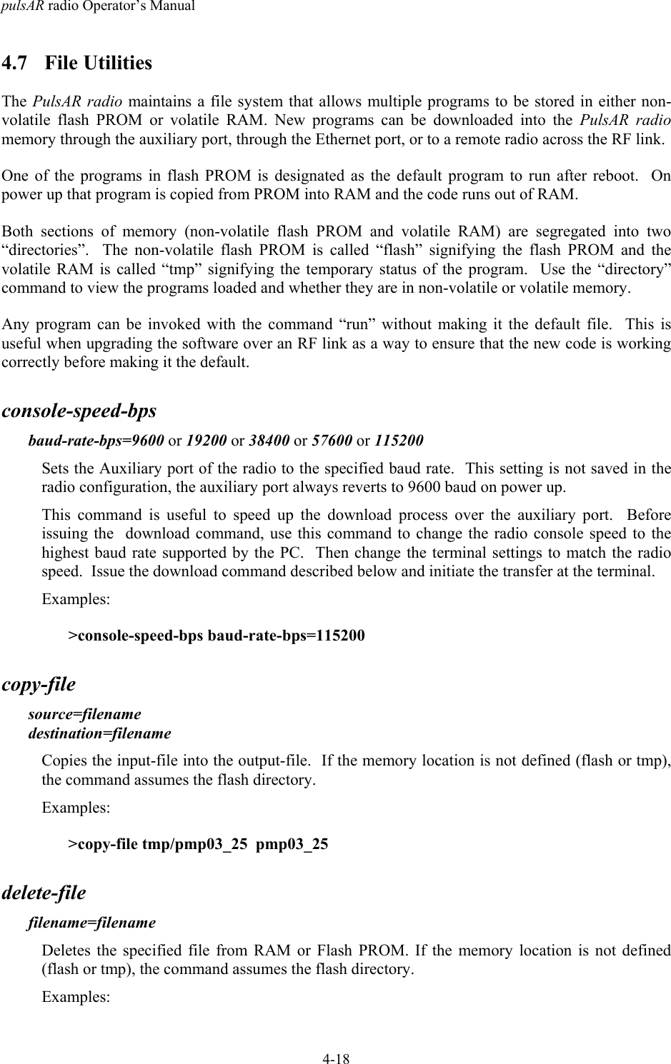
AFAR Communications 24110E Wireless Ethernet Bridge User Manual PulsAR Manual
AFAR Communications, Inc Wireless Ethernet Bridge PulsAR Manual
UserManual.wiki
>
AFAR Communications
>
24110E User Manual
User Manual
Navigation menu
Upload a User Manual
Namespaces
Wiki Guide
HTML
PDF
Info
Views
User Manual
Discussion / Help
Navigation
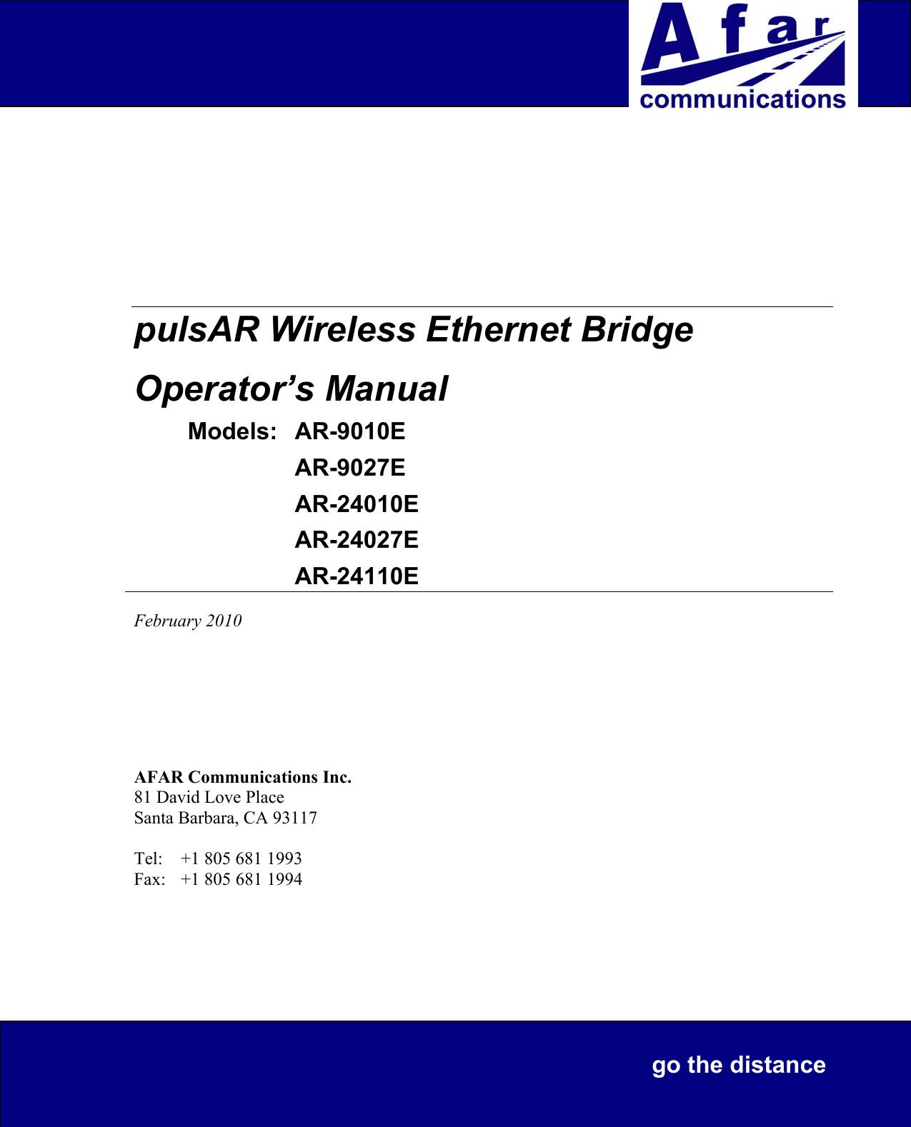
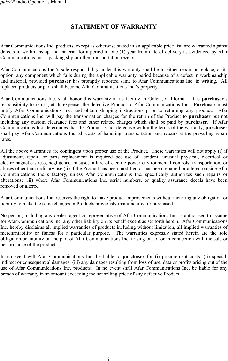
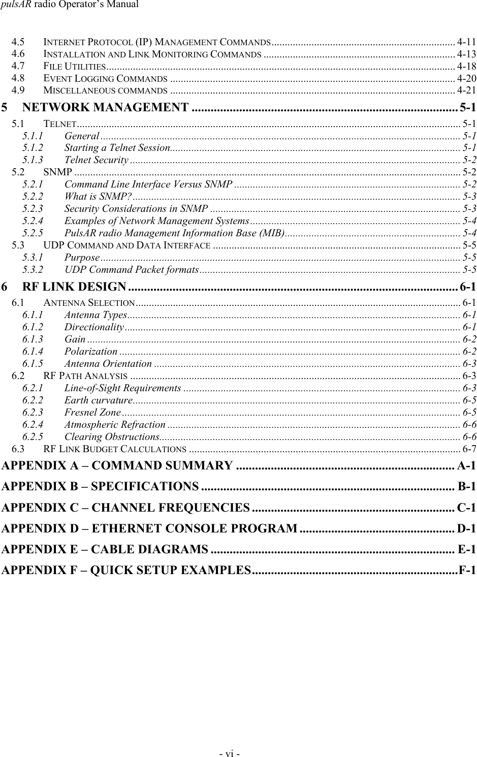
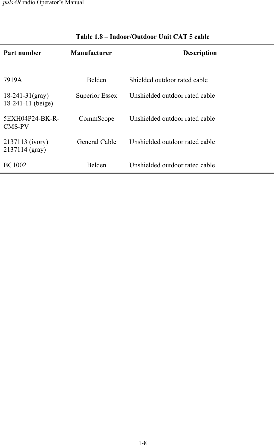
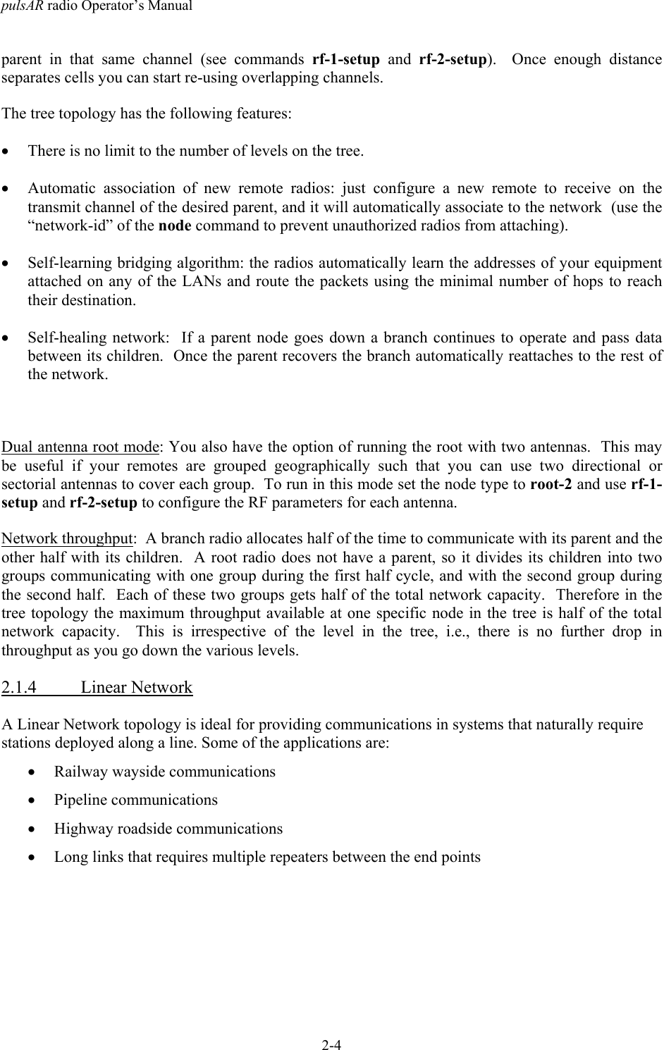
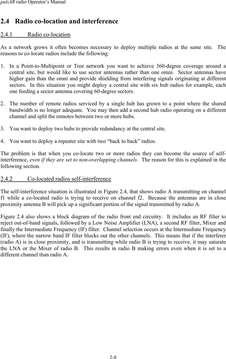

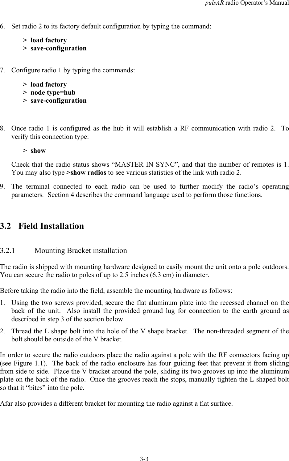
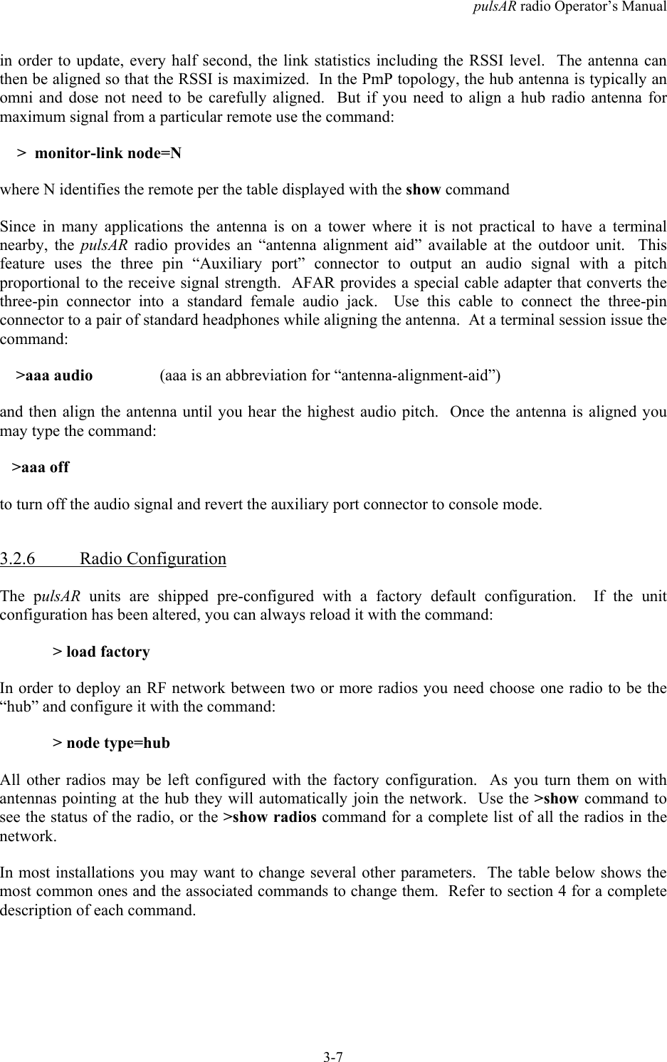
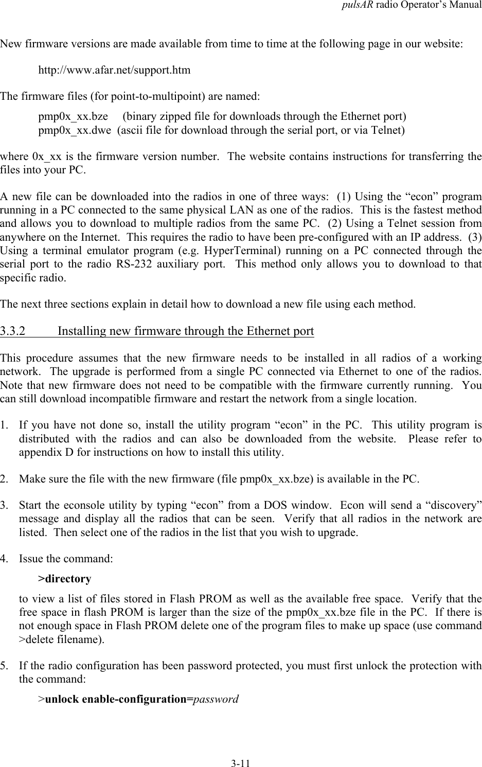
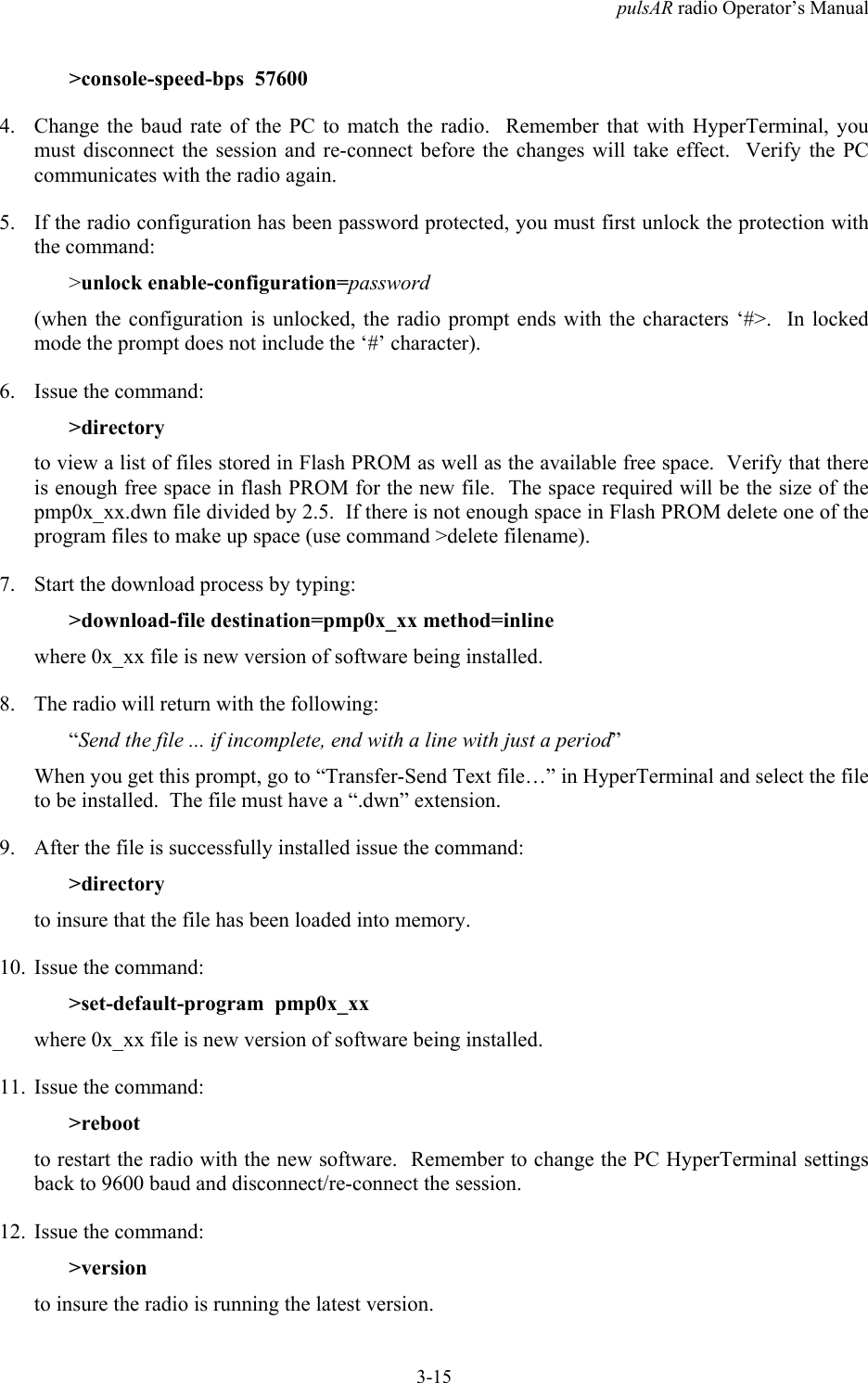
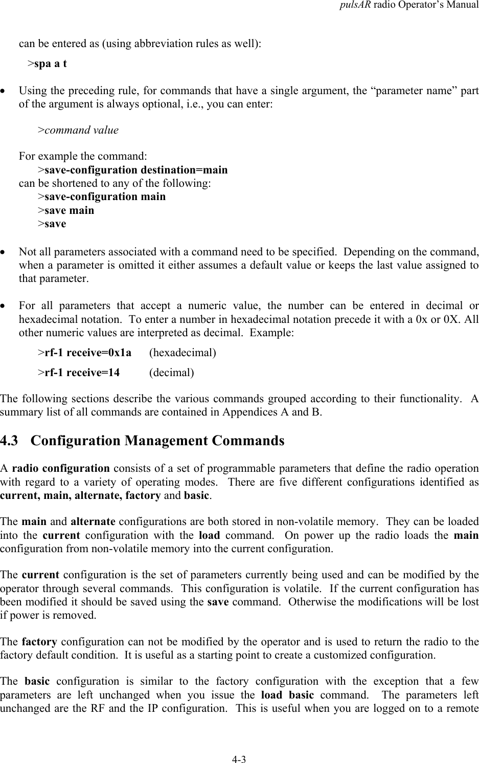
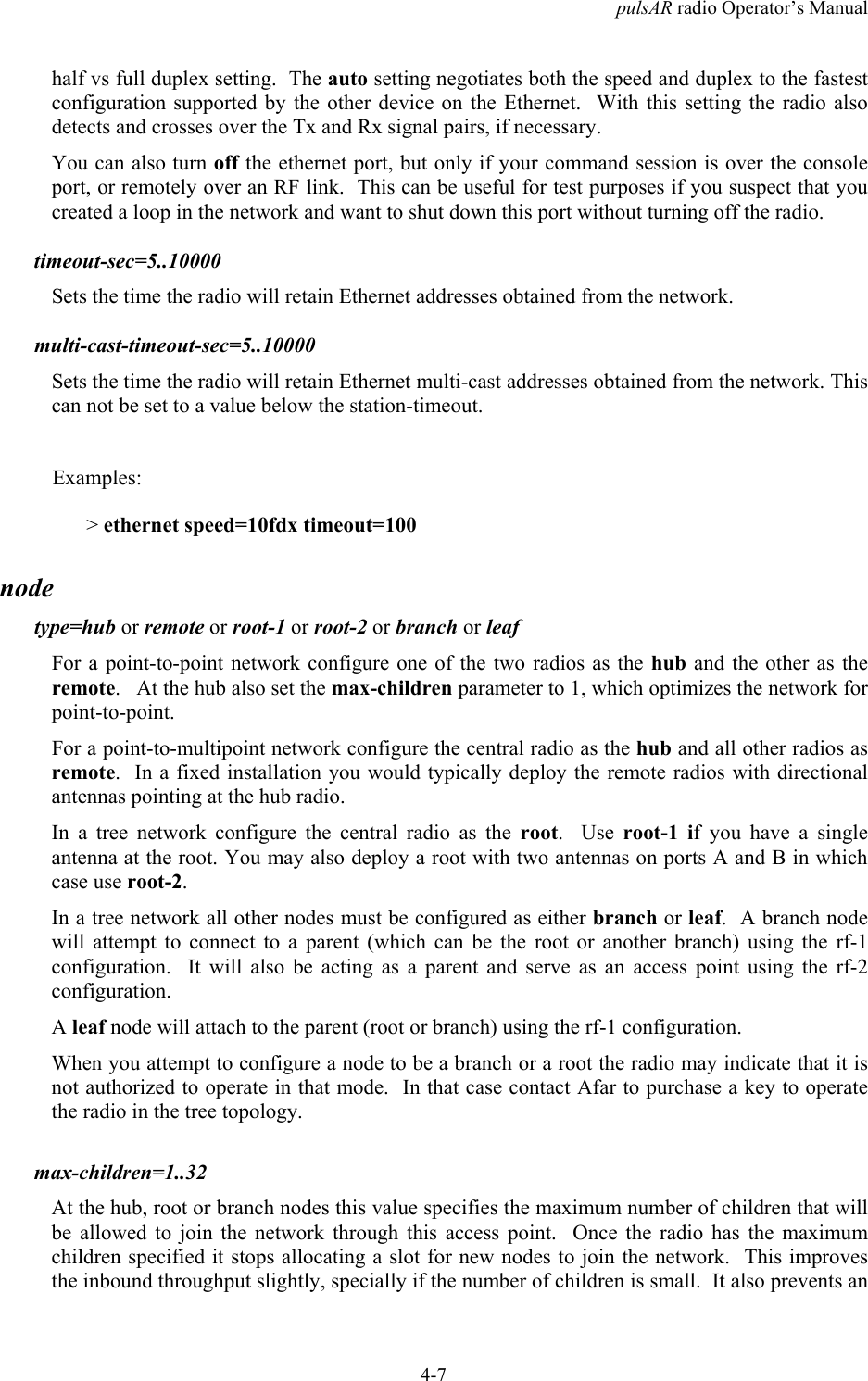
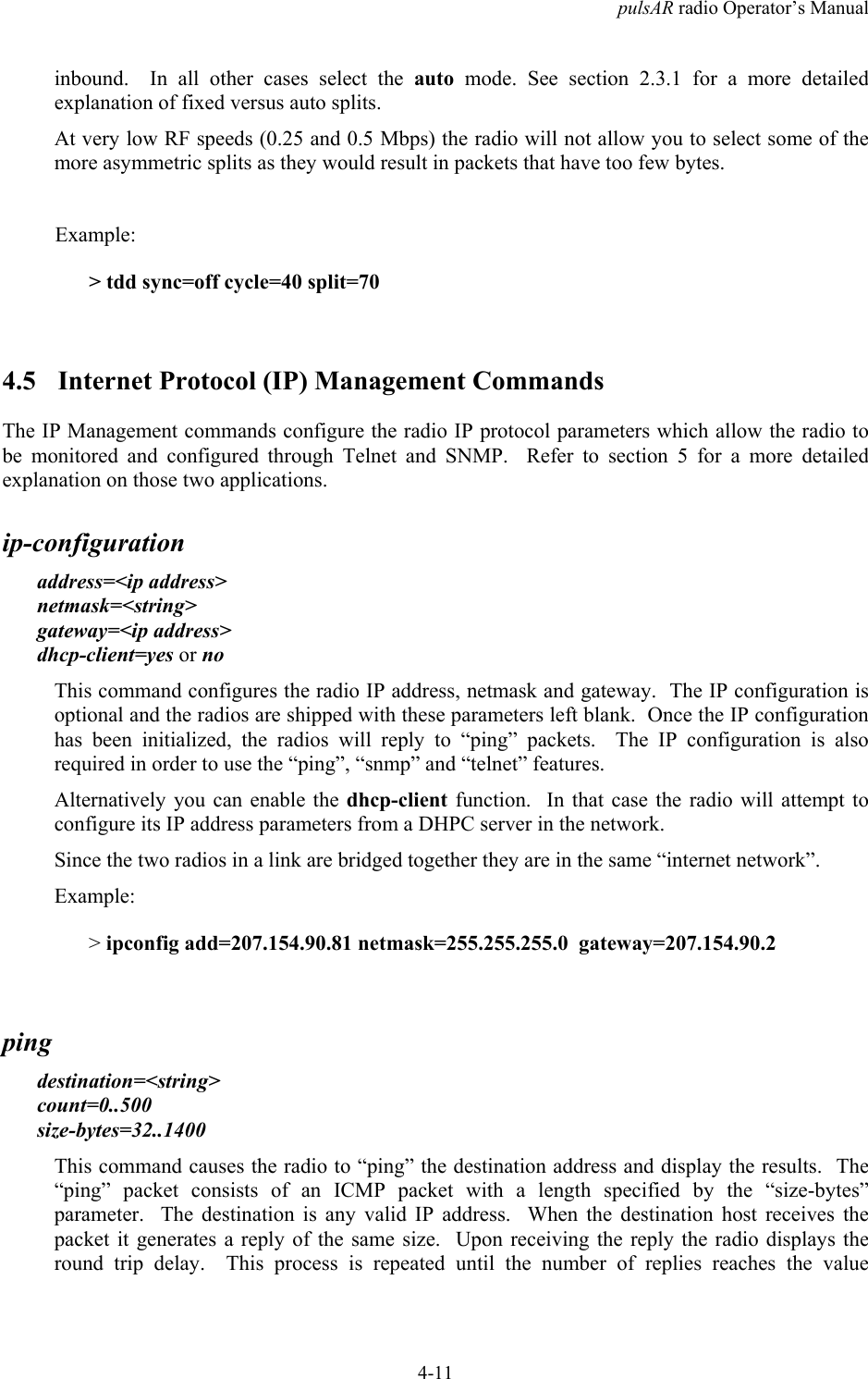
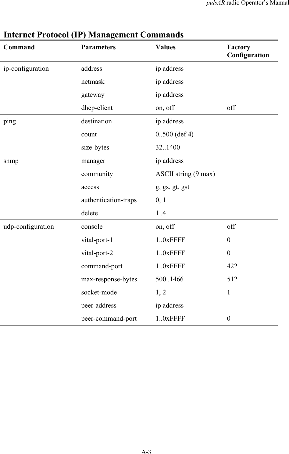
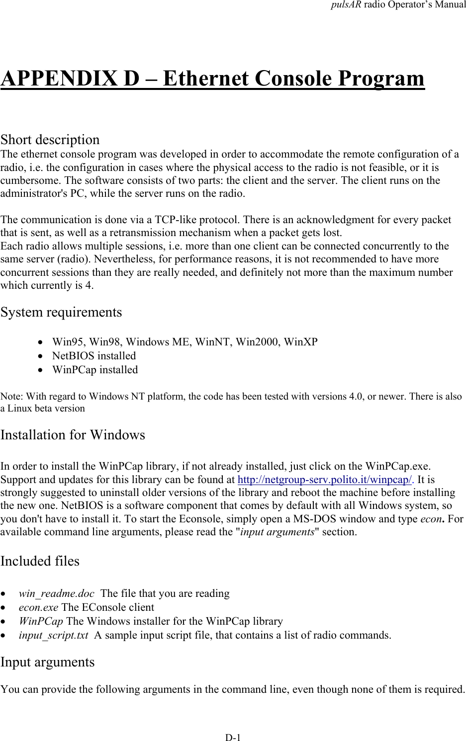
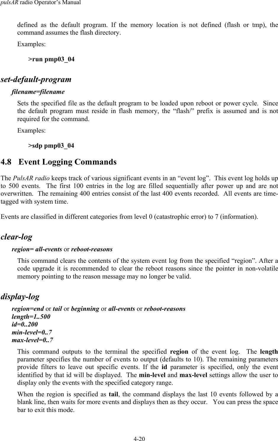
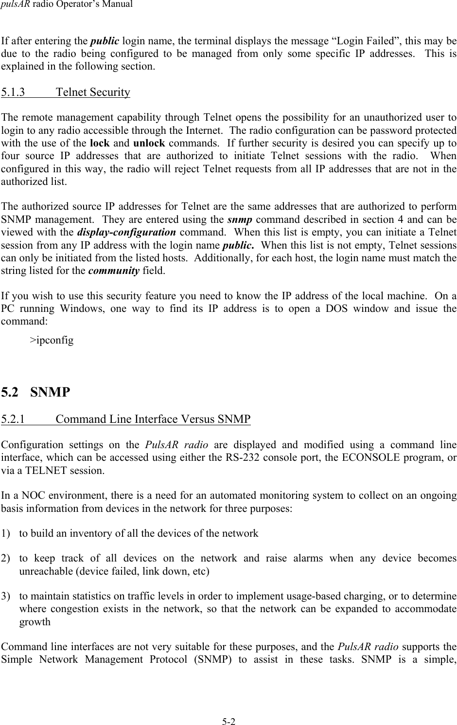
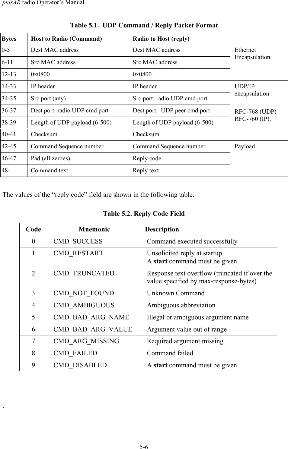
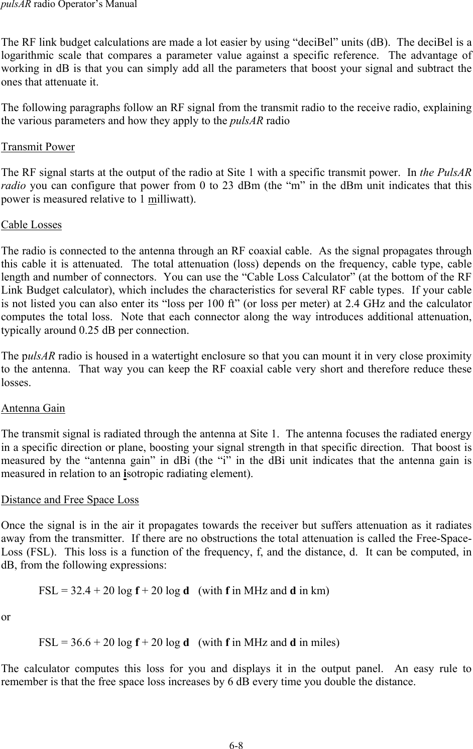
![pulsAR radio Operator’s Manual4-14antenna-alignment-aidmode=off or a-antenna or b-antennaWith the mode other than off, the radio outputs, through the auxiliary port, an audio signal witha pitch proportional to the Receive Signal Strength (RSS) level of packets received on thespecified antenna. AFAR provides a special cable adapter that converts the three-pin auxiliaryport connector into a standard female audio jack. Use this cable to connect the auxiliary port toa pair of standard headphones while aligning the antenna.While the antenna alignment is on the RS-232 console output is not available. When theantenna alignment output is set to off the auxiliary port output reverts to RS-232 console.The antenna alignment output setting can also be saved as part of the radio configuration. Thisis useful to take a pre-configured radio to an installation site with no need to turn the antennaalignment ON (through a terminal) after power up.Example:>aaa a-antenna>aaa offmonitor-flowThis command continuously displays the current and peak data rates to and from all the radiosthat have a direct link with this one. Press the [space bar] to terminate the command.monitor-linknode=1, 4..Nclear=0 or 1This command continuously displays link statistics including the RSSI at both ends of the link,link distance, percent of packets lost, and the elapsed time since this link has been up. Youmust specify a valid node number from the list displayed by the show links command (if thisradio is involved in only one link you do not need to enter the node number). Press the [spacebar] to terminate the command.The “clear=1” parameter clears the percent of dropped packets statistic. You can also clear thatstatistic by pressing the “zero” key while the command is running.Examples:>monitor-link node=4 clear=1monitor-roamingIf a radio is configured to roam between multiple hubs, this command shows which hubs arecurrently within range, and the Receive Signal Strength (RSSI) from each hub. The report alsoidentifies the current hub that this radio is attached to. This information is refreshed once persecond. Press the [space bar] to terminate the command.](https://usermanual.wiki/AFAR-Communications/24110E/User-Guide-1262897-Page-62.png)
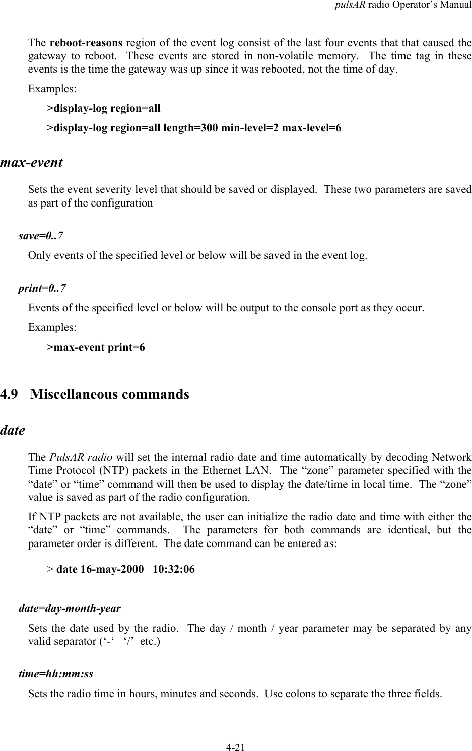
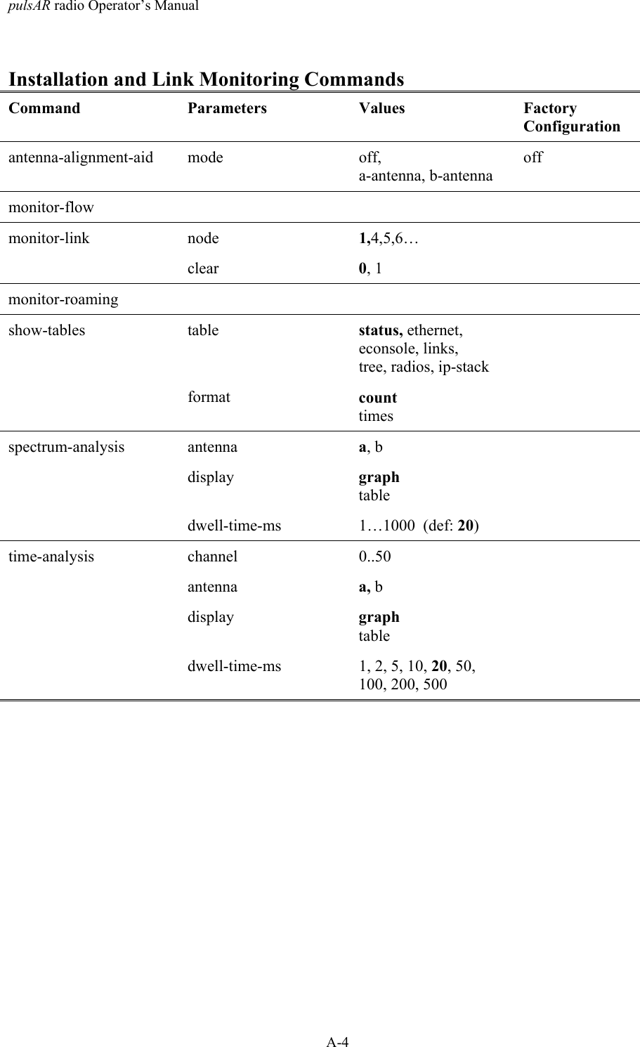
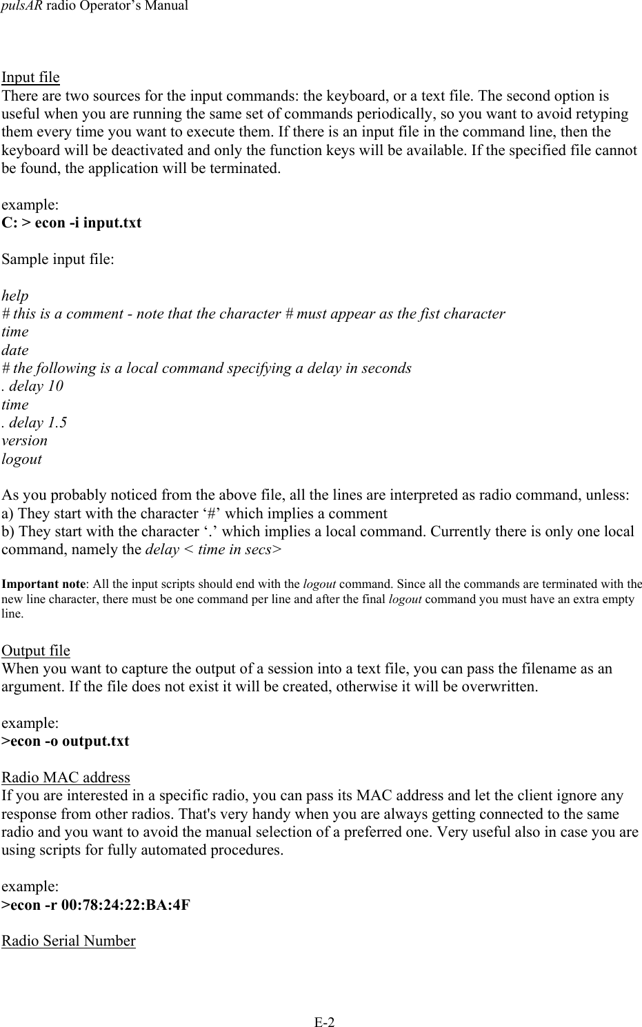
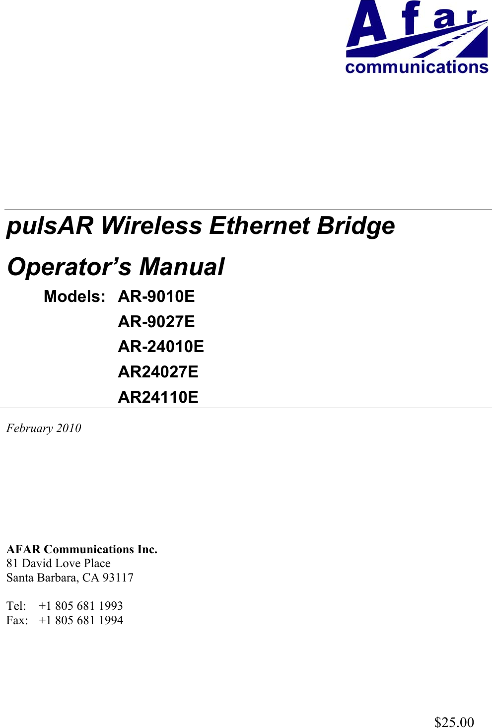
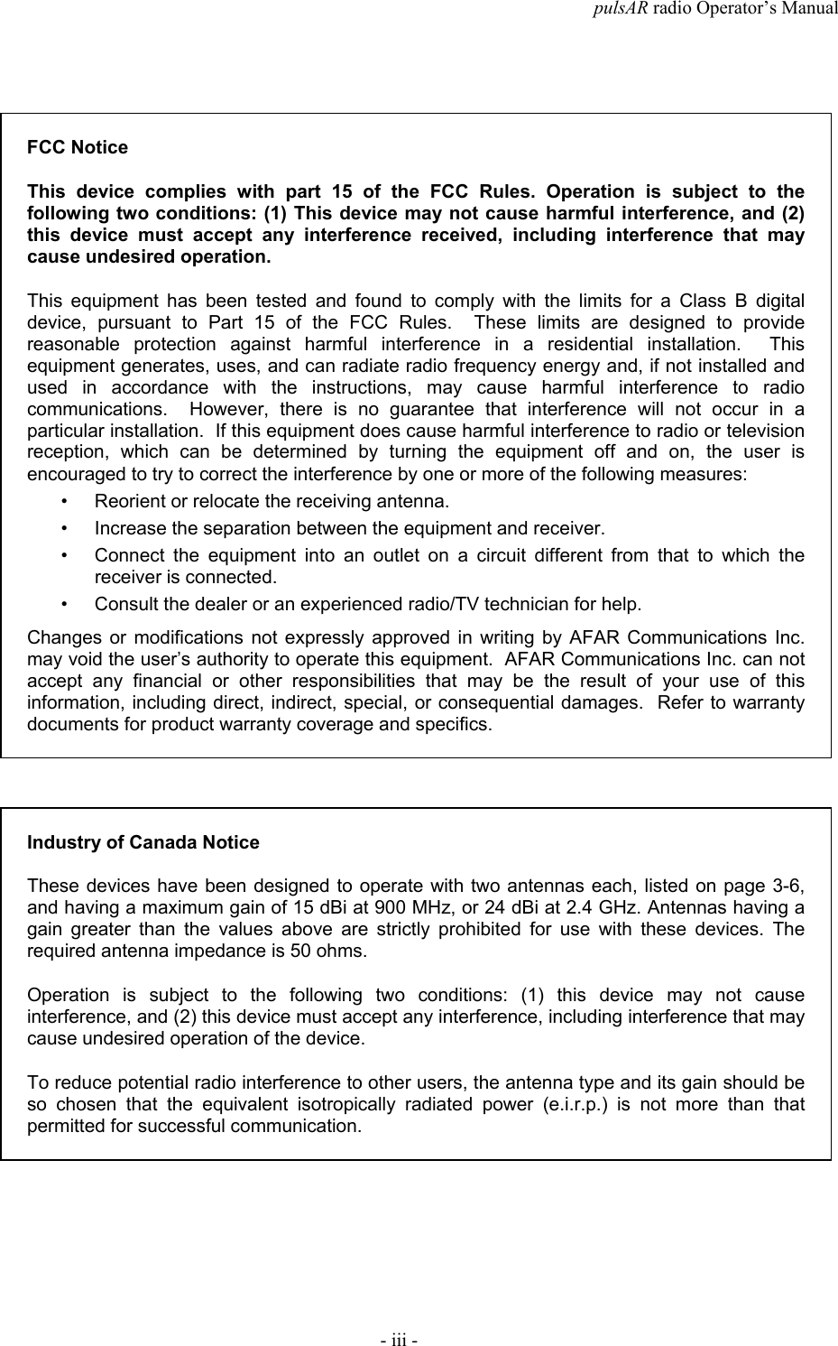
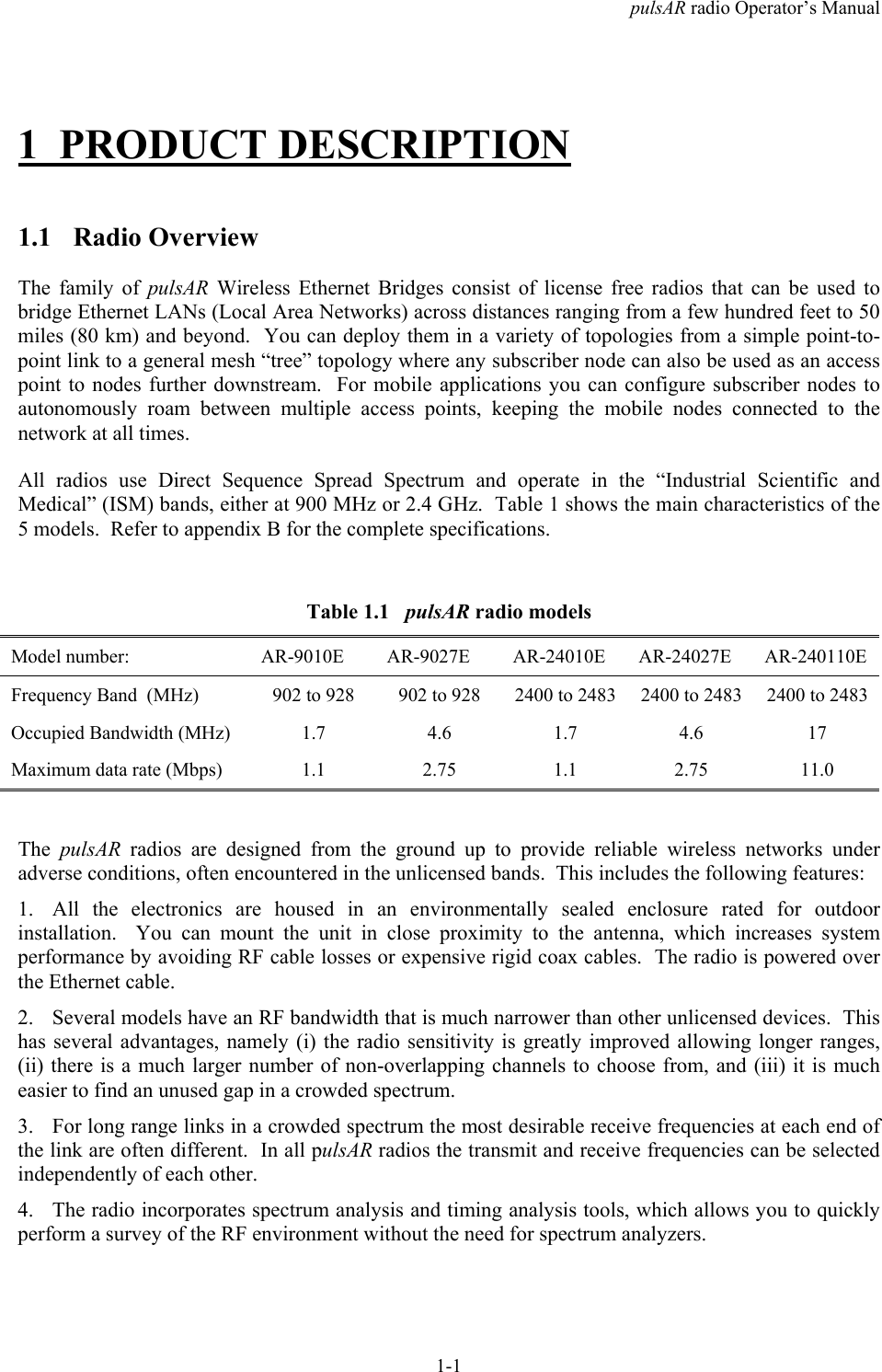
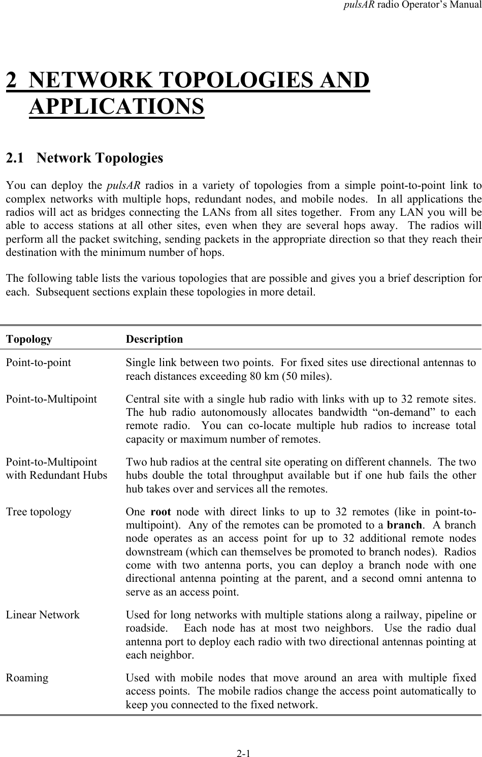
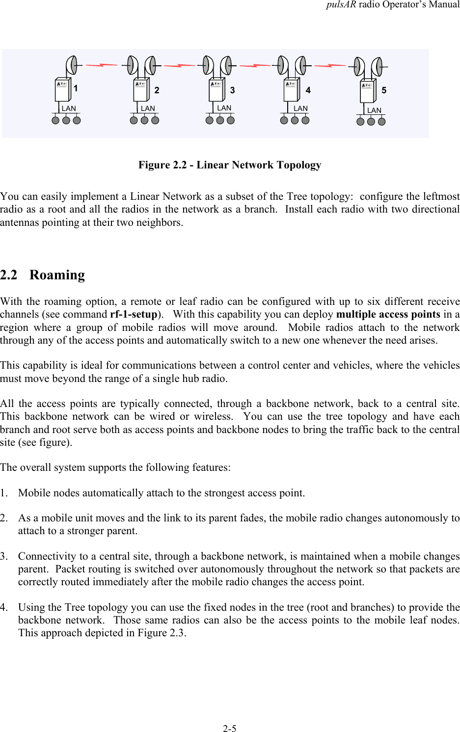
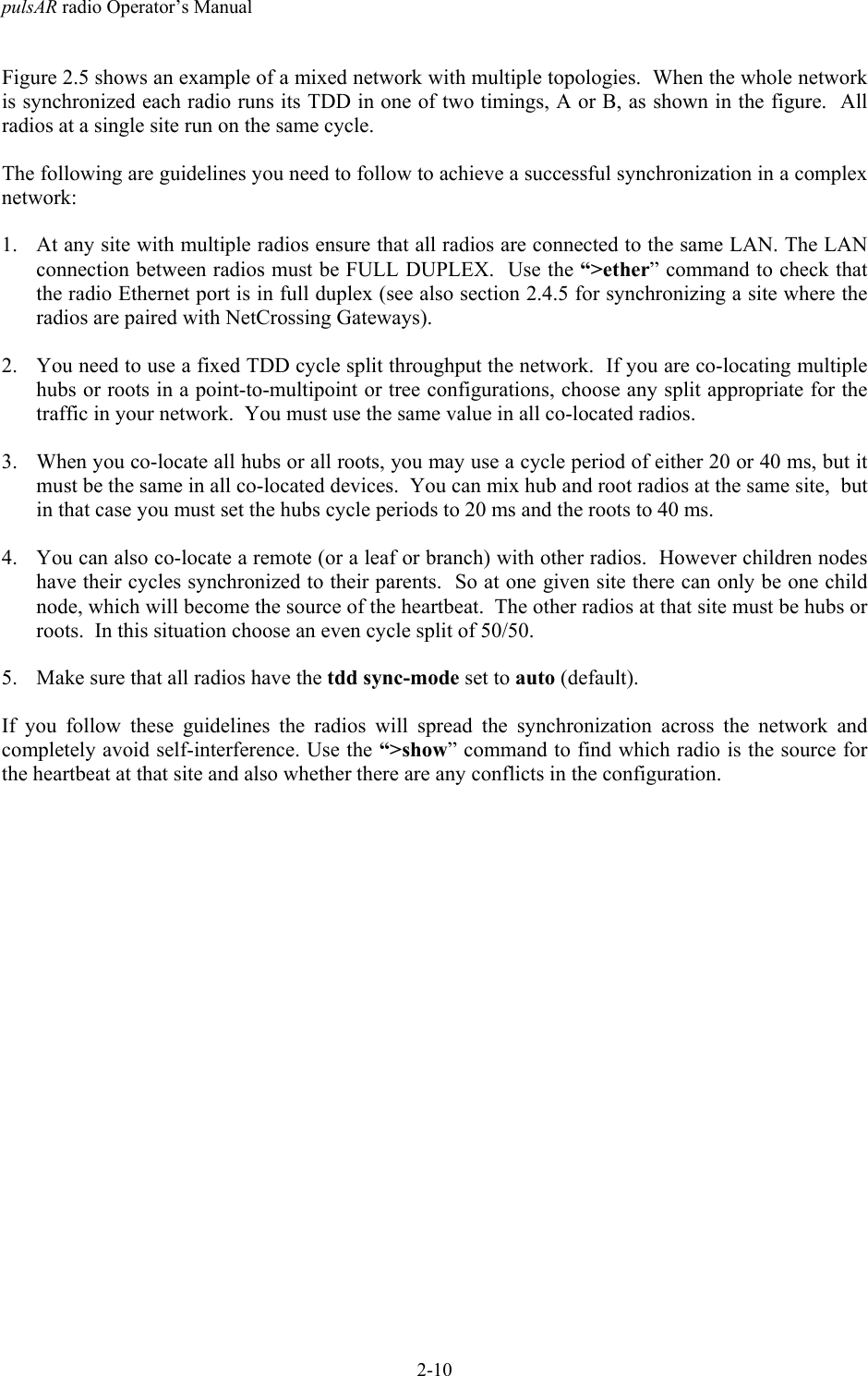
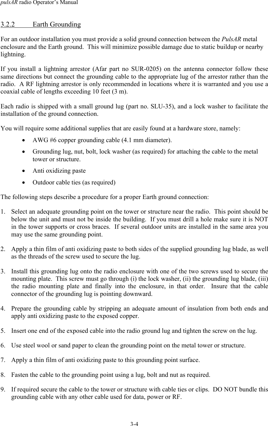
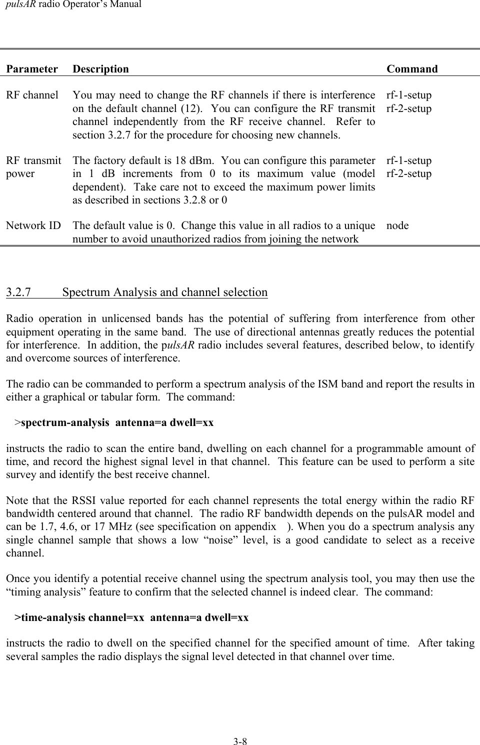
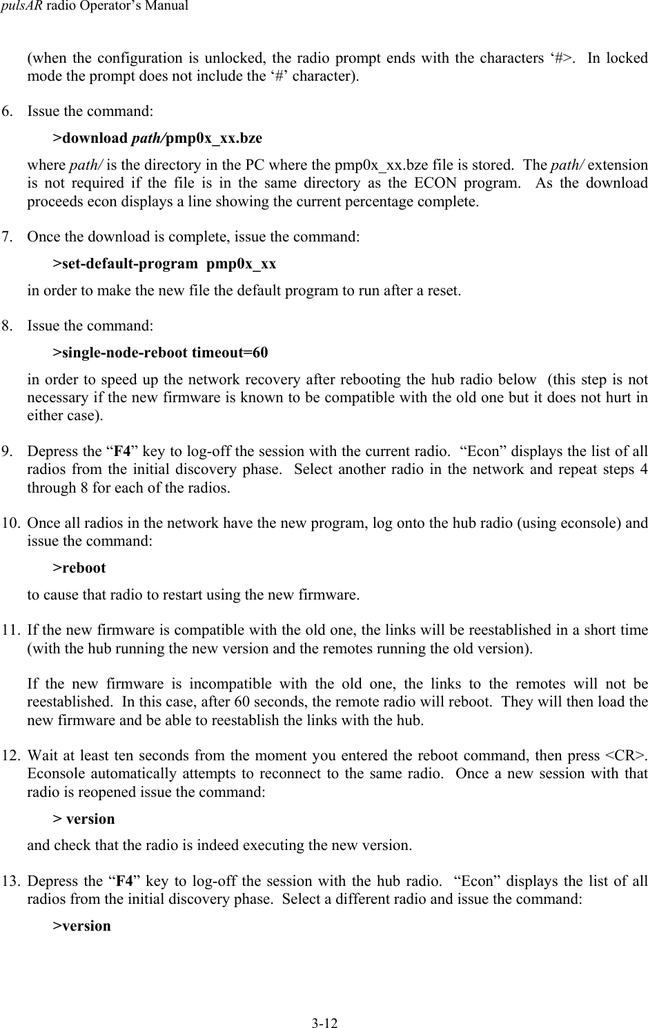
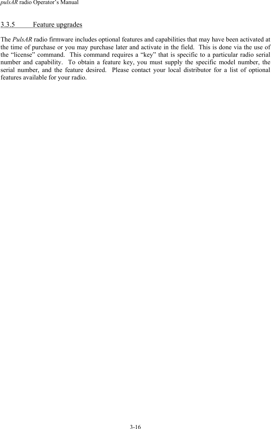
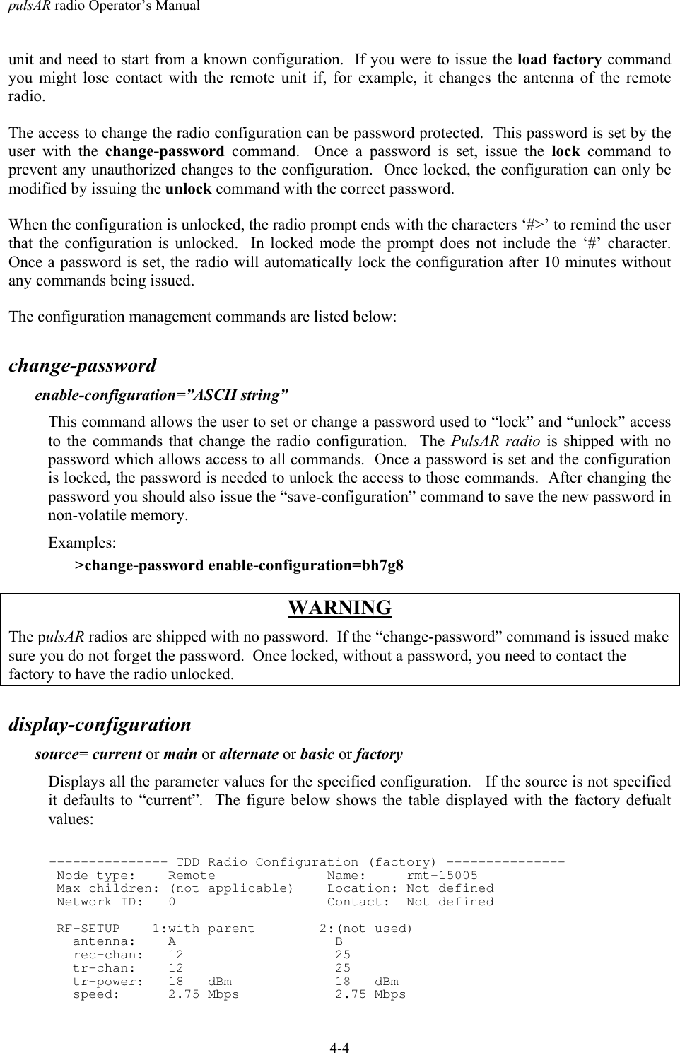
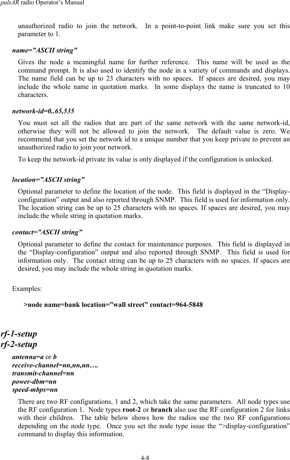
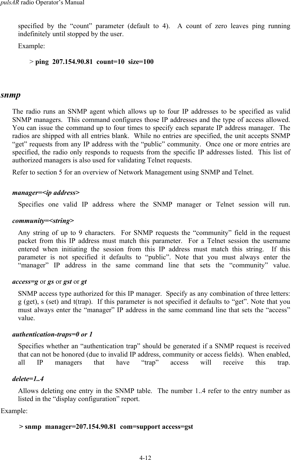
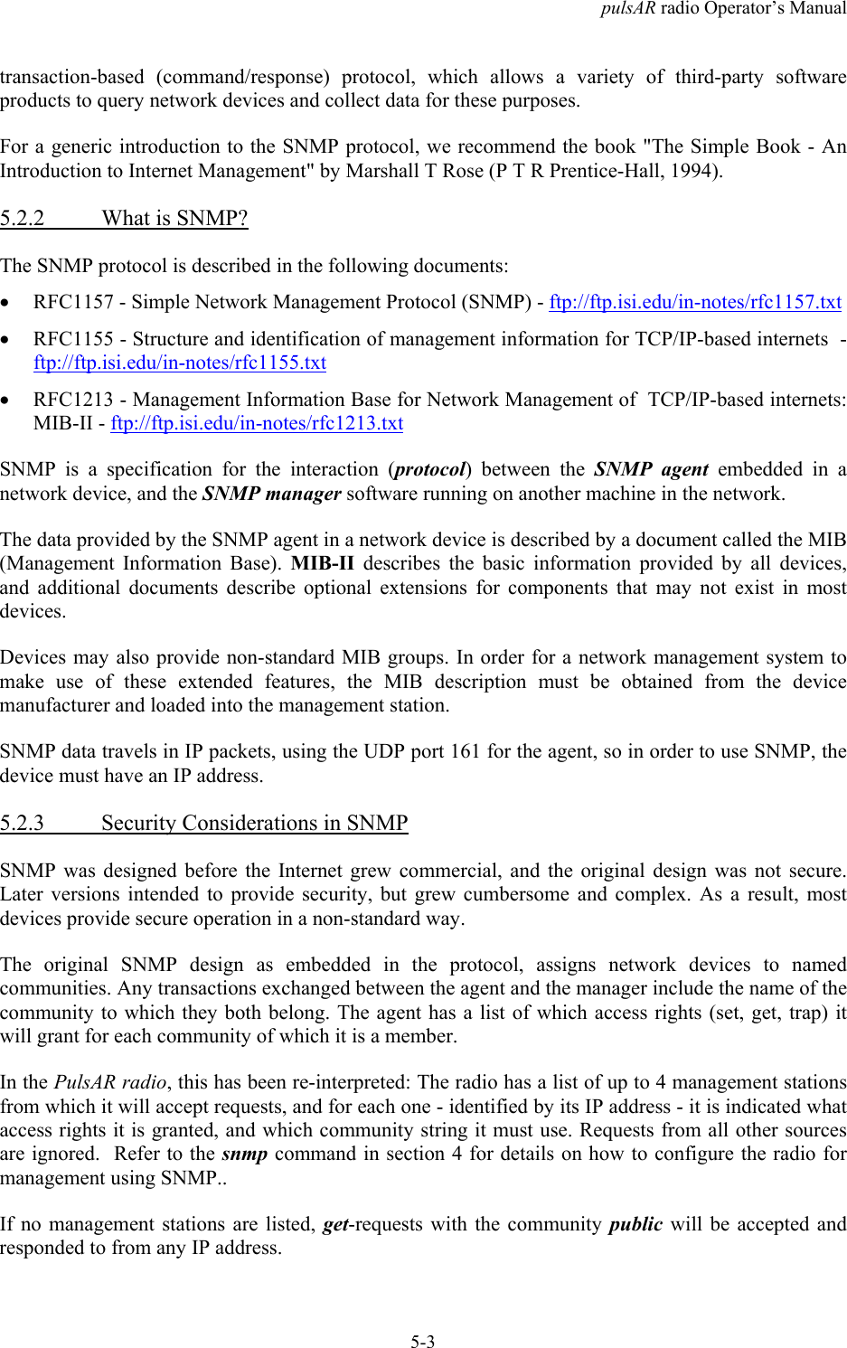
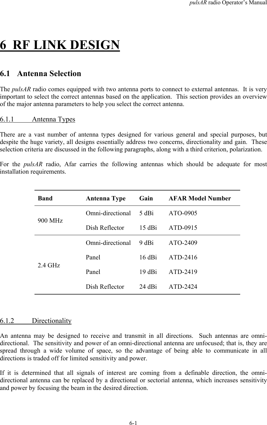
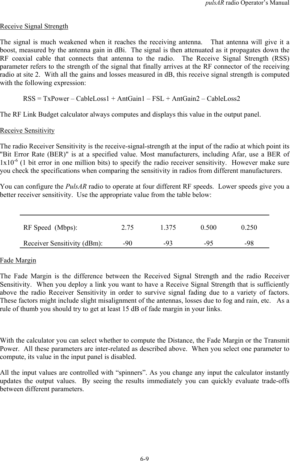
![pulsAR radio Operator’s Manual4-22zone=zone-code or offsetSets the time zone to be used by the radio to translate the NTP time to local time. It can bespecified by an offset from GMT (-0800 or +0200 for example), or as a “zone-code”. The valid“zone-codes” and the respective offsets are shown below:Zone zone code offsetPacific Standard Time PST -0800Pacific Daylight Time PDT -0700Mountain Standard Time MST -0700Mountain Daylight Time MDT -0600Central Standard Time CST -0600Central Daylight Time CDT -0500Eastern Standard Time EST -0500Eastern Daylight Time EDT -0400Greenwich Mean Time GMT 0000help [command-name]If no command is specified, displays the complete list of commands. If a command is specifiedit displays the valid parameter and corresponding values for that specific command.Examples:>help monitor-linkhistoryDisplays the previous commands entered.licensekey=< ASCII string>The “license” command is used to turn ON or OFF a set of optional features or capabilities. Thekey is a 35-character string combination of ASCII letters, numbers, and hyphens. The key mustbe input with the syntax as shown in the example below, including hyphens, for the radio toaccept it. The characters can be input as upper or lower case.After entering the key you must reboot the radio for the feature, enabled by the key, to takeeffect.Each key is unique for a particular radio serial number and capability, i.e. a key generated toturn ON a capability on one serial number will not work on another radio.Example:>license key=02EL1-ZGZ42-G0000-00C54-81WAJ-C9BEK](https://usermanual.wiki/AFAR-Communications/24110E/User-Guide-1262897-Page-70.png)
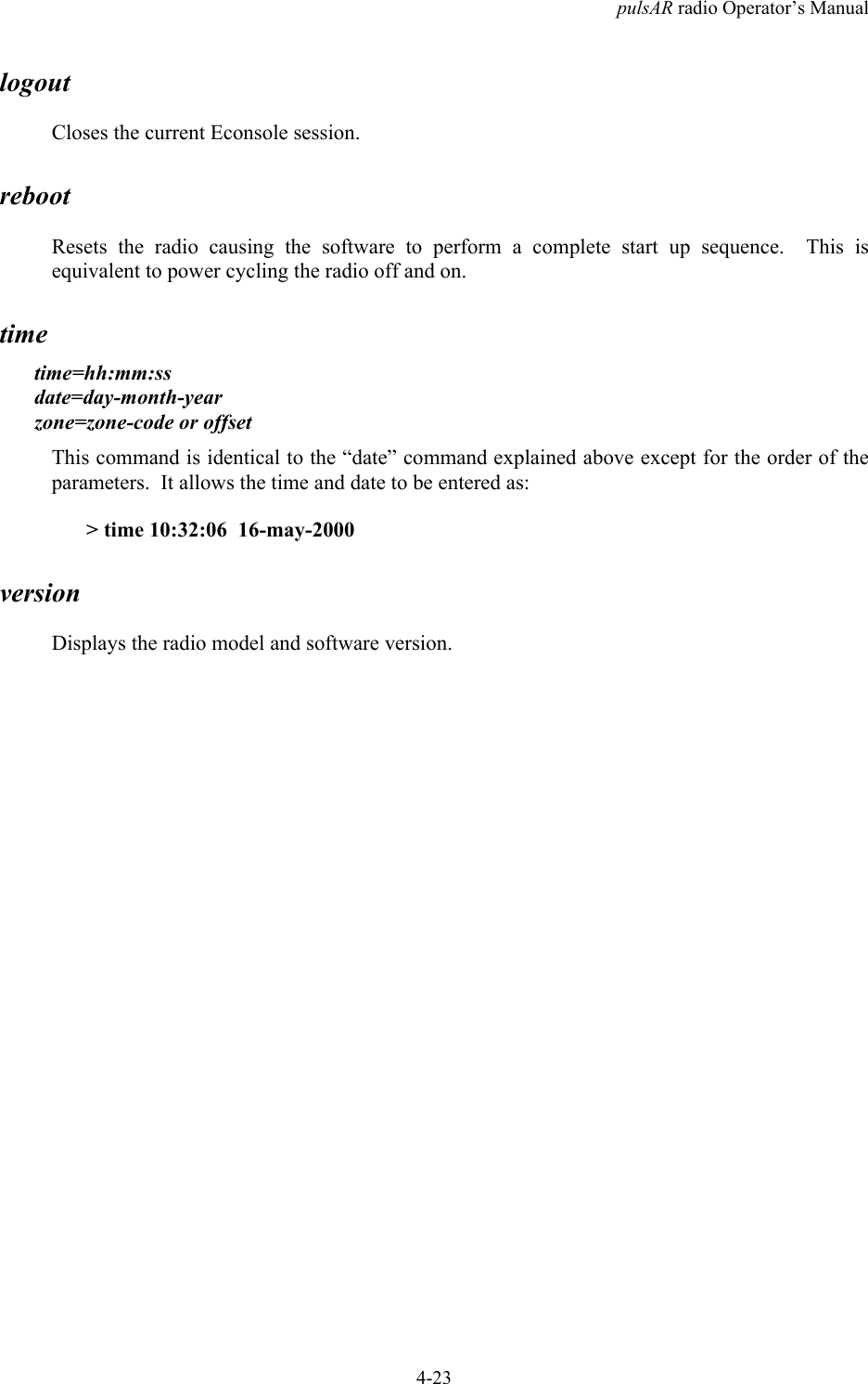
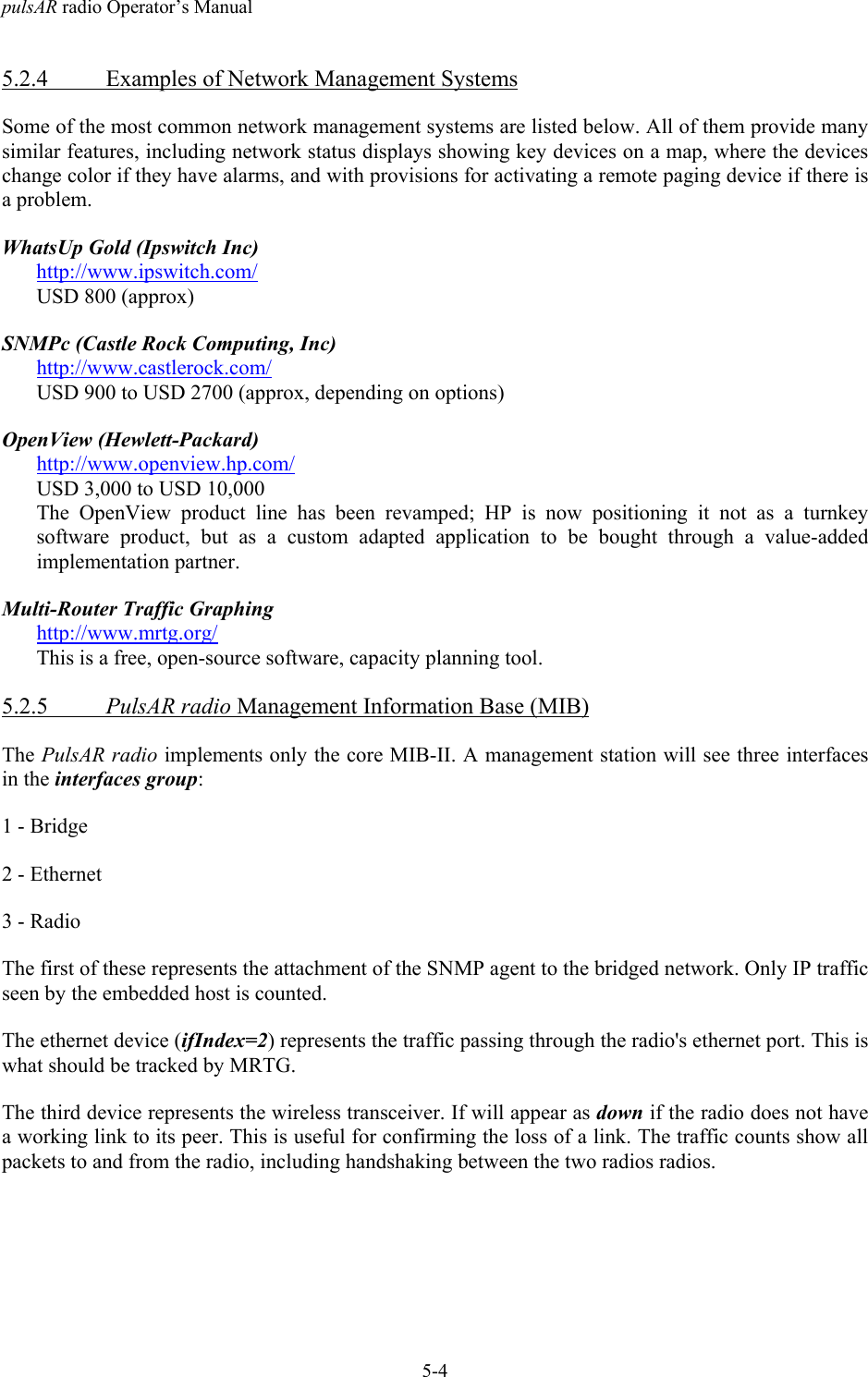
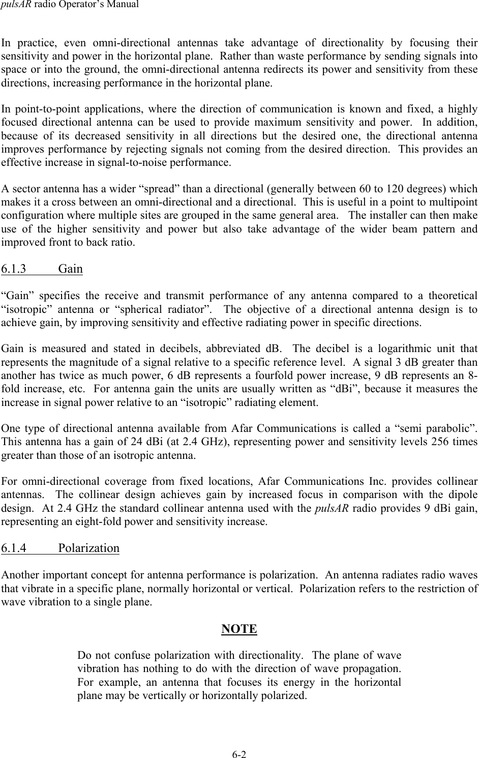
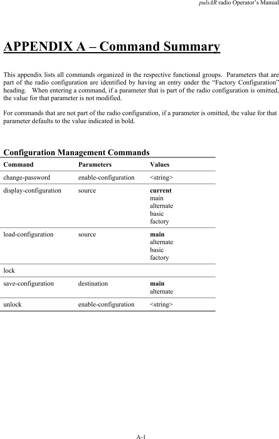
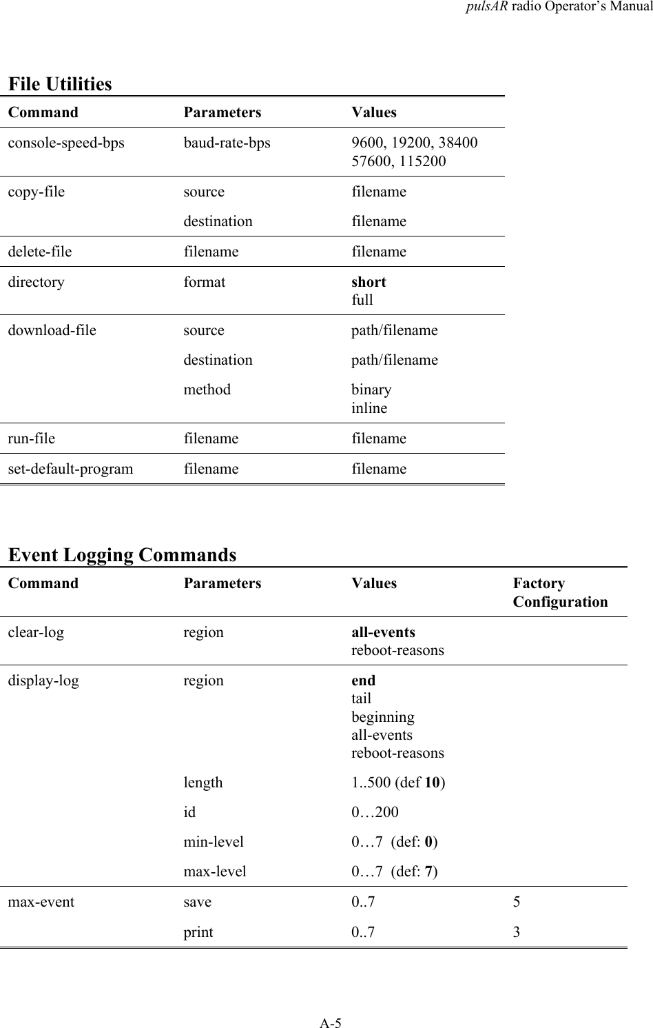
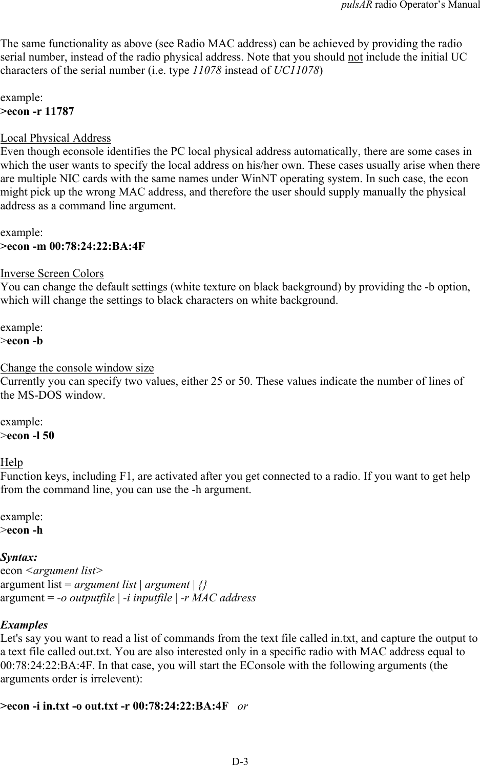
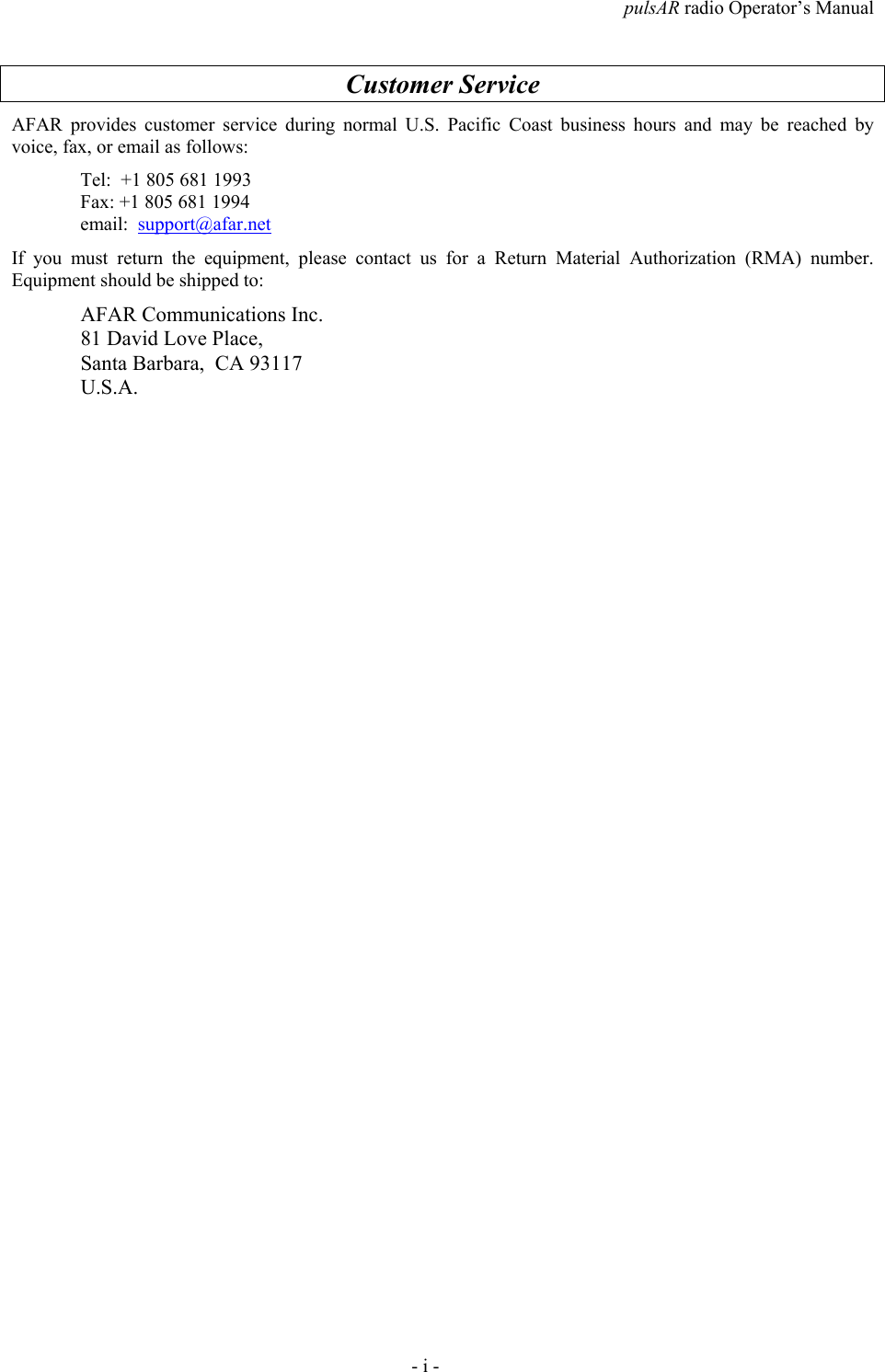
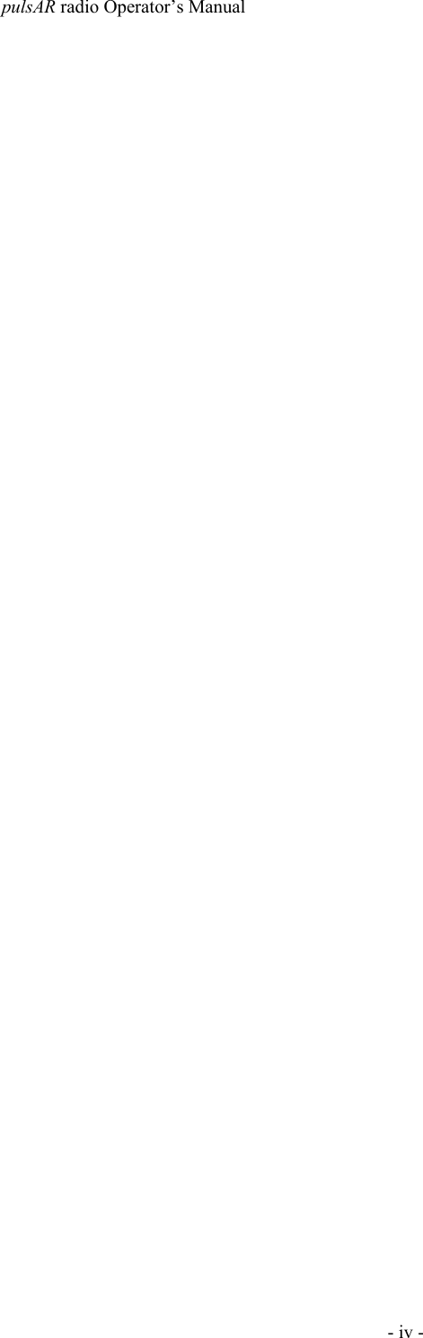
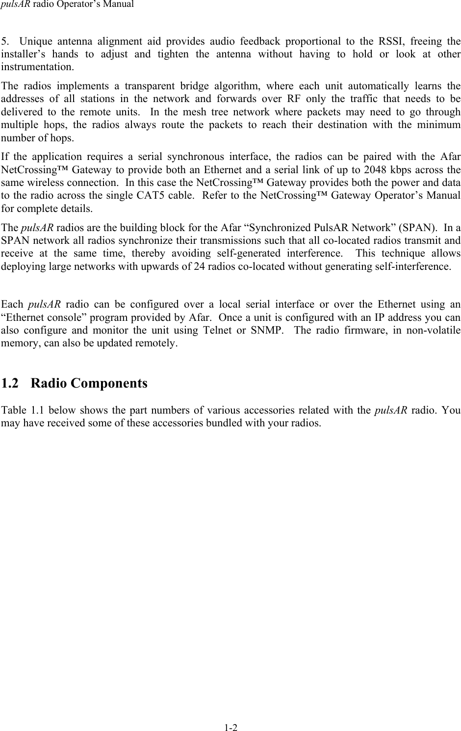
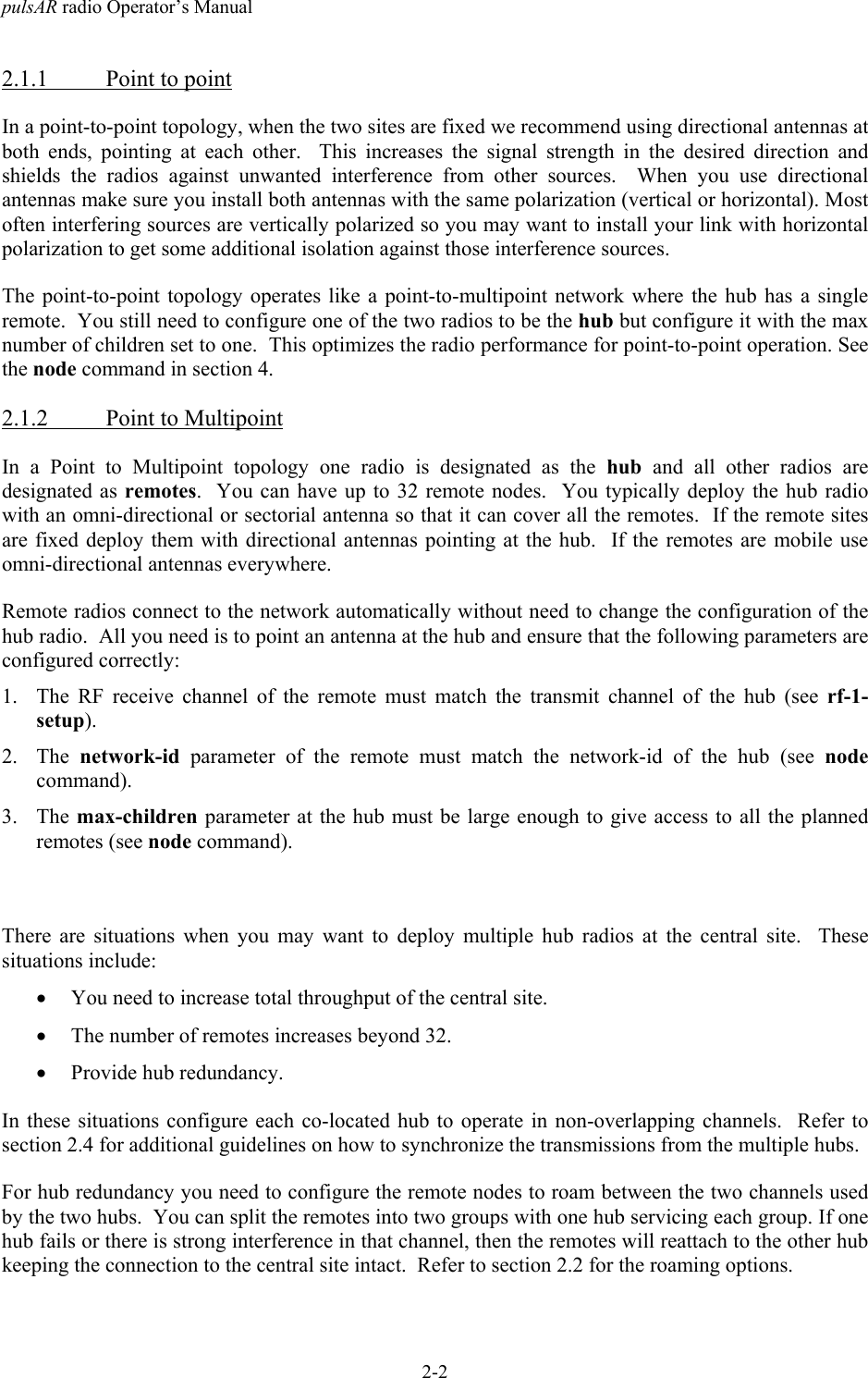
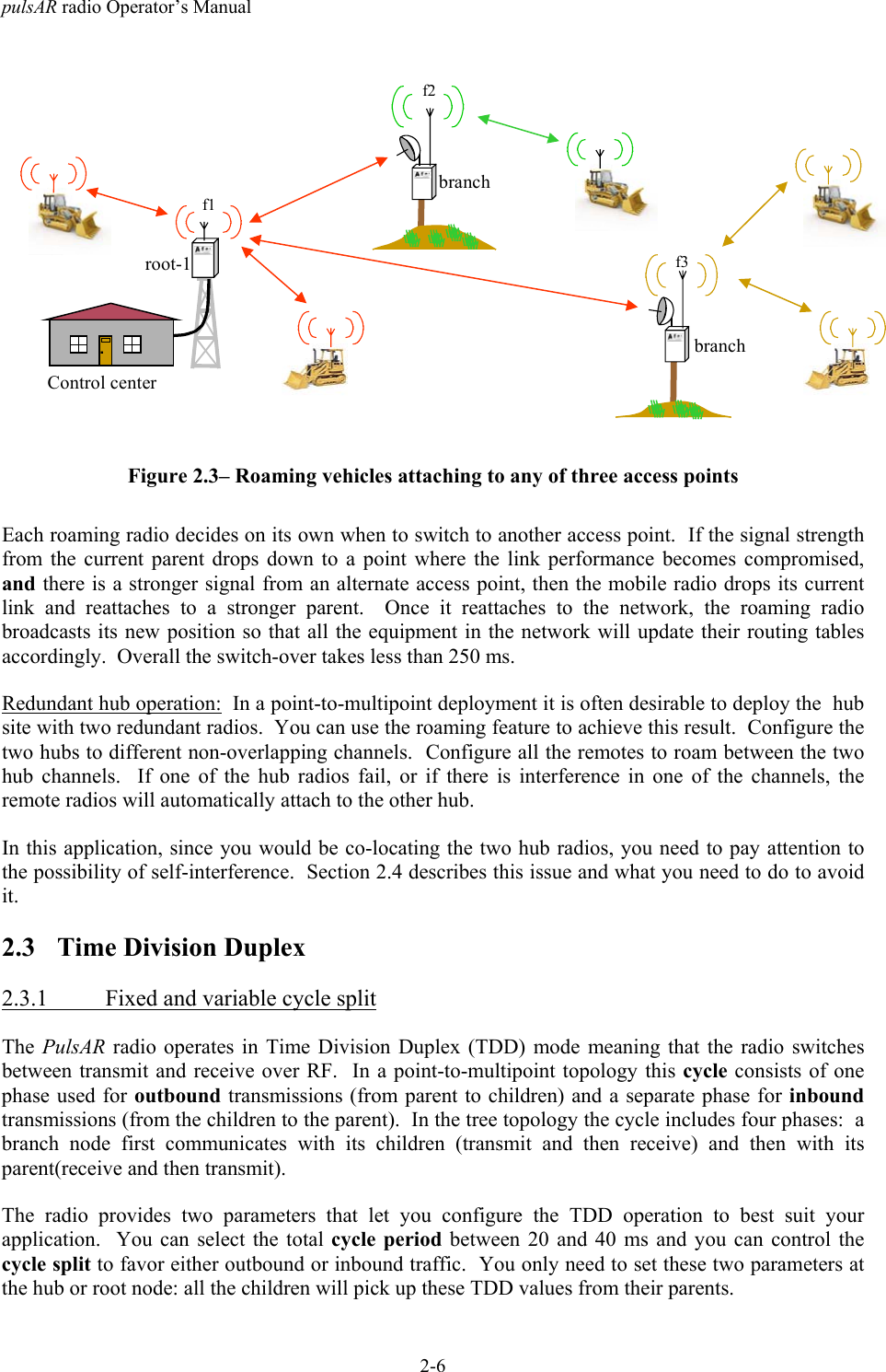
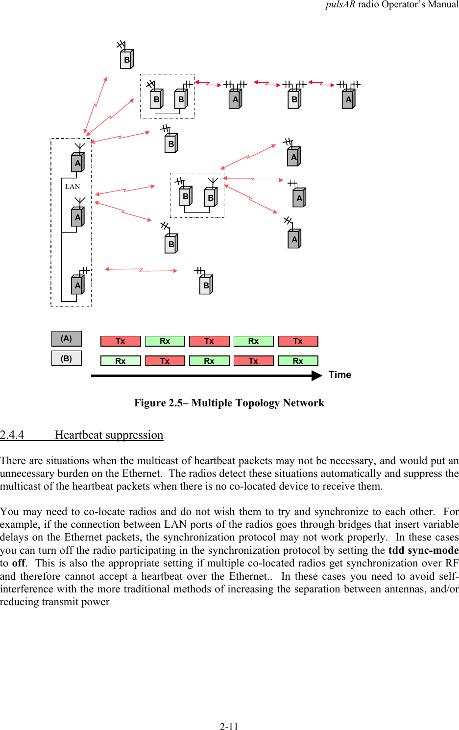
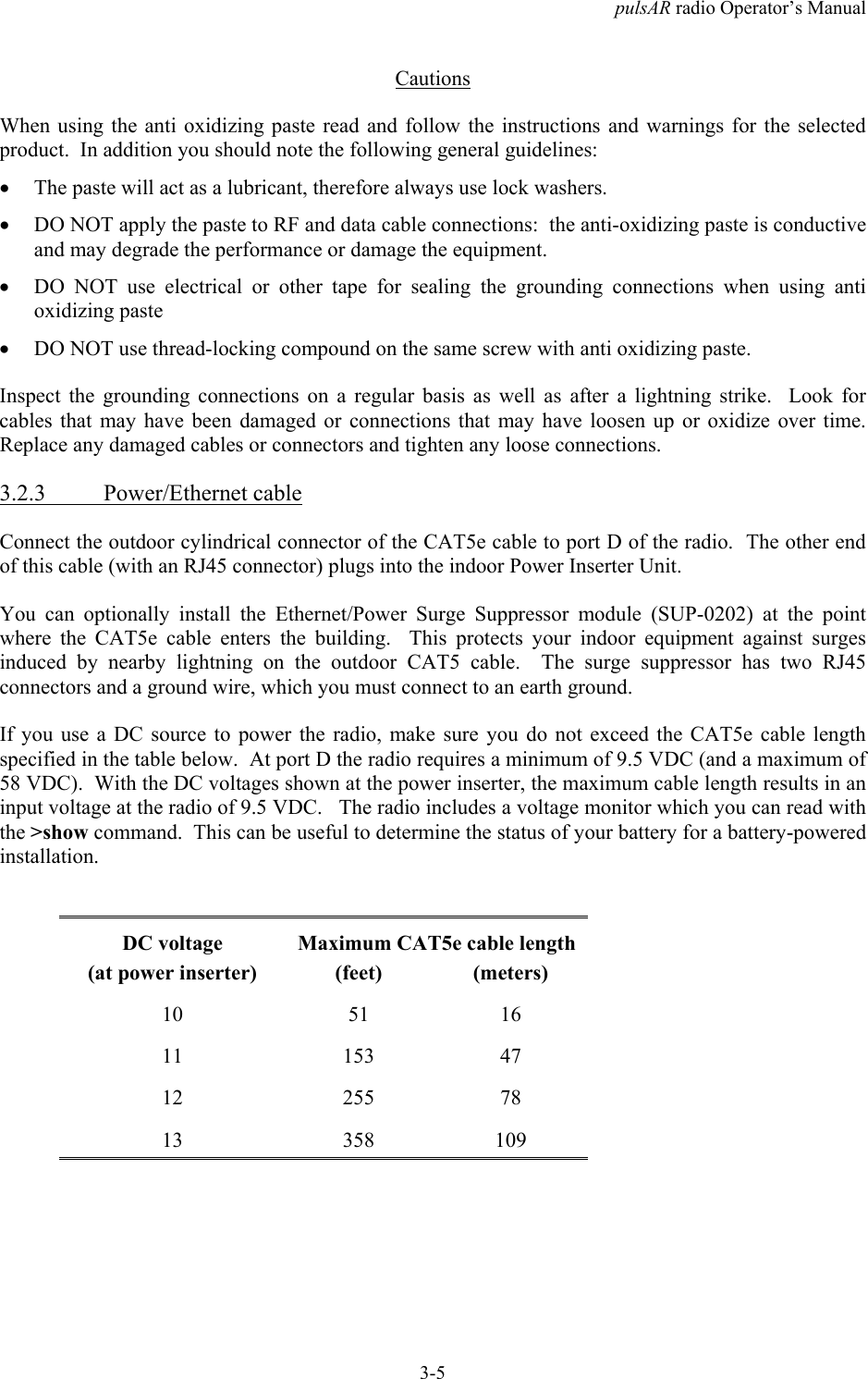
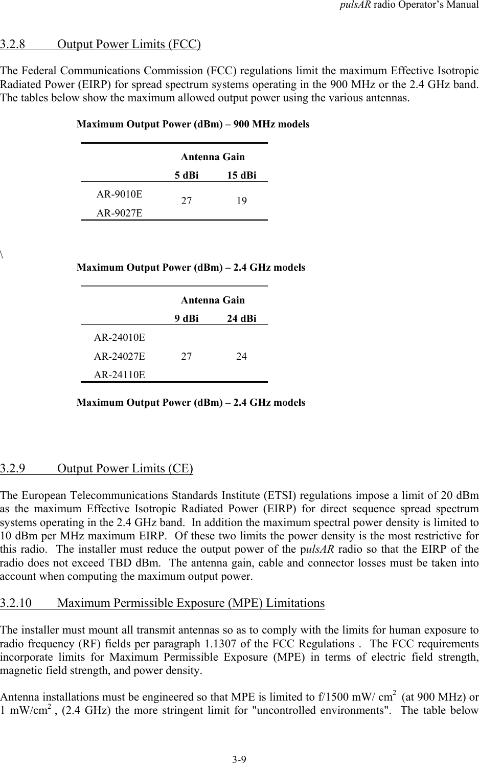
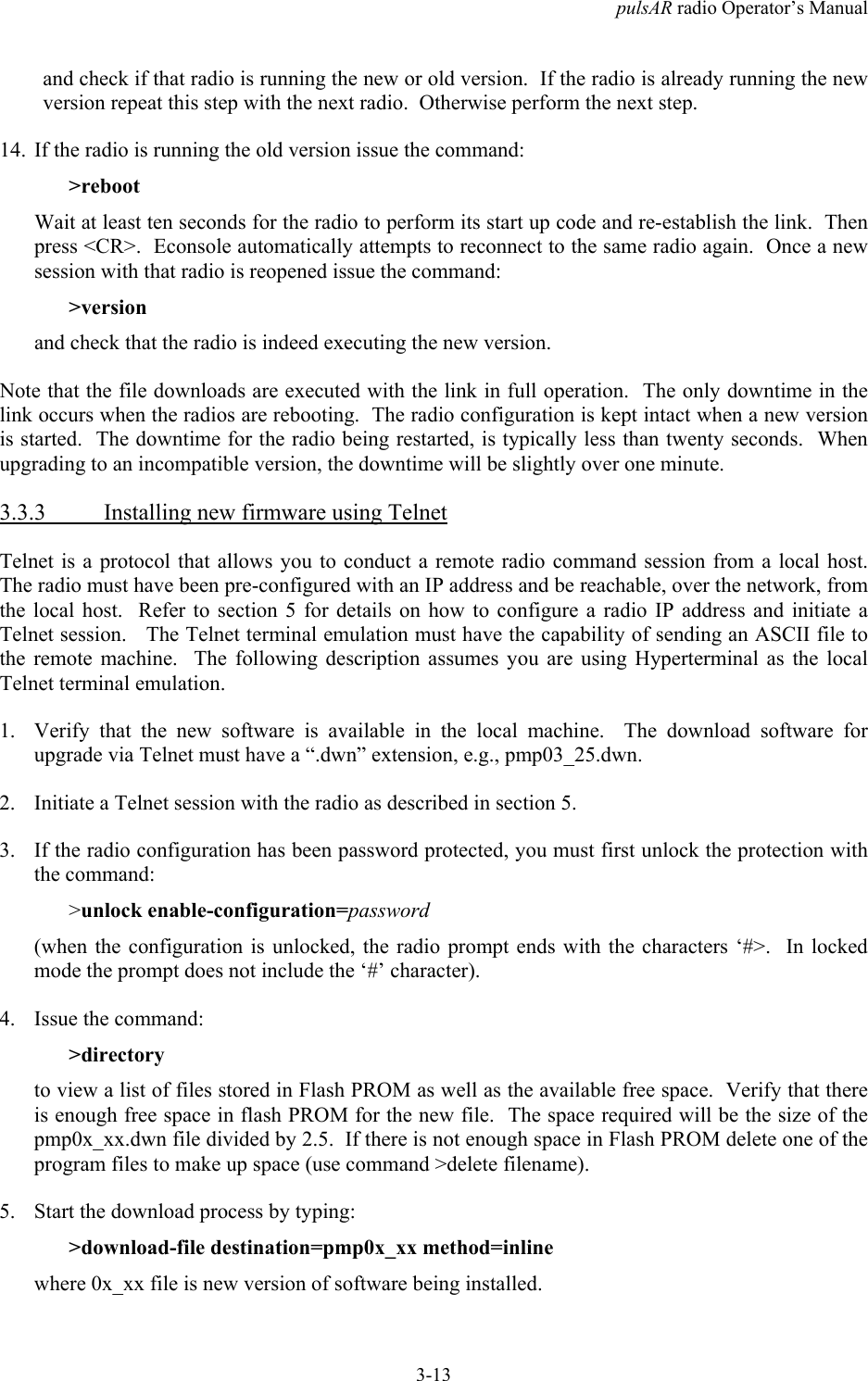
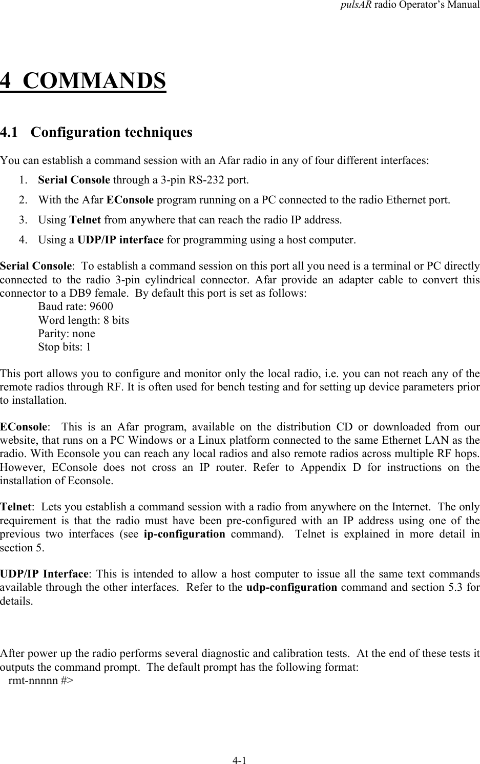
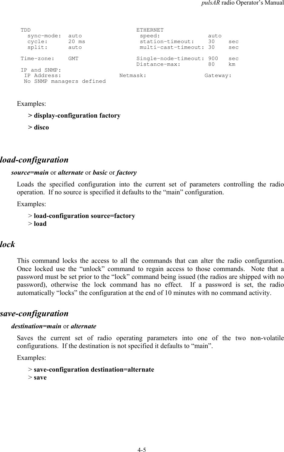
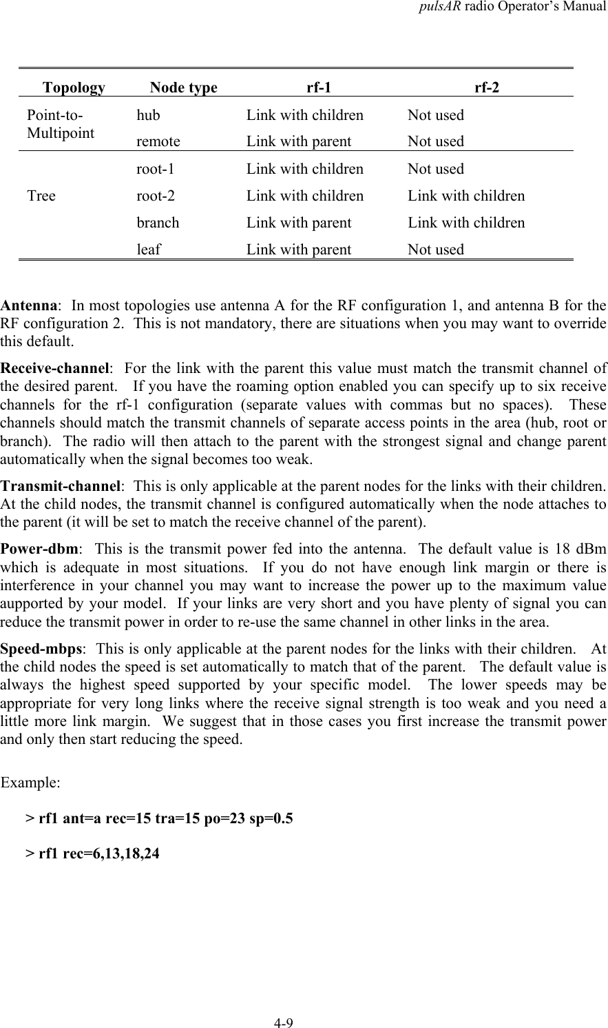
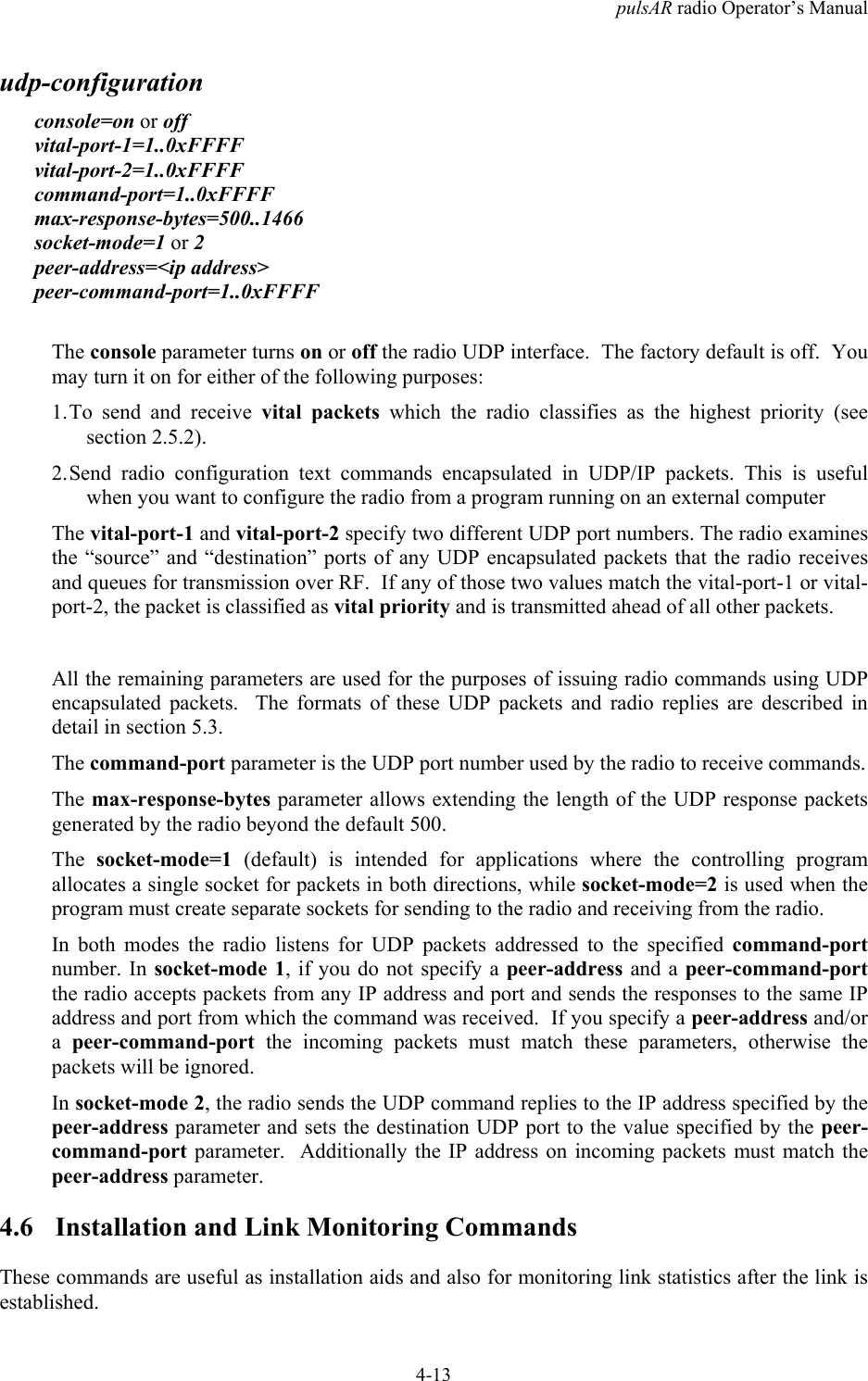
![pulsAR radio Operator’s ManualA-2Major Configuration ParametersCommand Parameters Values FactoryConfigurationdistance-max maximum 10..160 80units km or miles kmethernet speed auto-10, 10hdx, 10fdx100hdx, 100fdx, auto,offautotimeout-sec 5..10000 30multi-cast-timeout-sec 5..10000 30node type hub, remote, root-1,root-2, branch, leafremotemax-remotes 1..32 32name (23 character string) rmt-nnnnnnetwork-id 0..65535 0location (25 character string)contact (25 character string)rf-1-setup antenna a, b rf-1: a, rf-2: brf-2-setup receive-channel min..max rf-1: 12 rf-2: 25transmit-channel min..max rf-1: 12 rf-2: 25speed-mbps [speeds] maxpower-dbm 0..max_power 18single-node-reboot timeout-sec 15..20000 900time-division-duplex sync-mode off, auto autocycle-period-ms 20, 40 20split-outbound-percent auto, 10, 20, 30, 40,50, 60, 70, 80, 90auto](https://usermanual.wiki/AFAR-Communications/24110E/User-Guide-1262897-Page-90.png)