AISOLUTION KDC200 Barcode Reader User Manual KDC200 User Manual 1 2
AISOLUTION CO., LTD. Barcode Reader KDC200 User Manual 1 2
UserManual.wiki
>
AISOLUTION
>
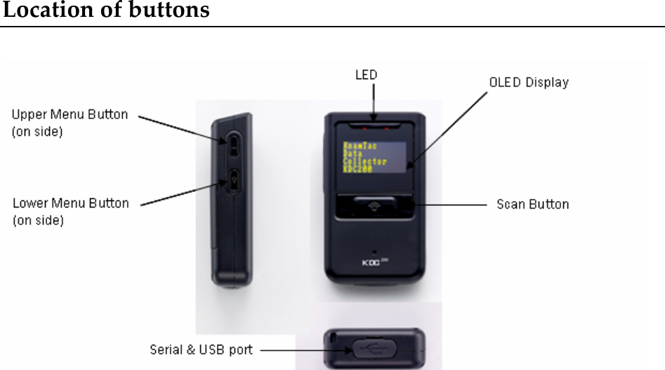
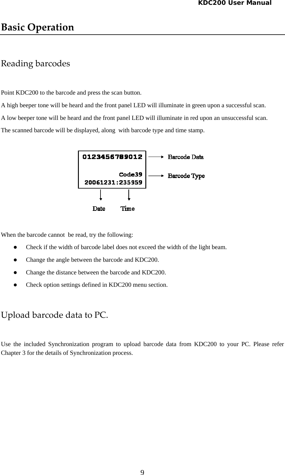
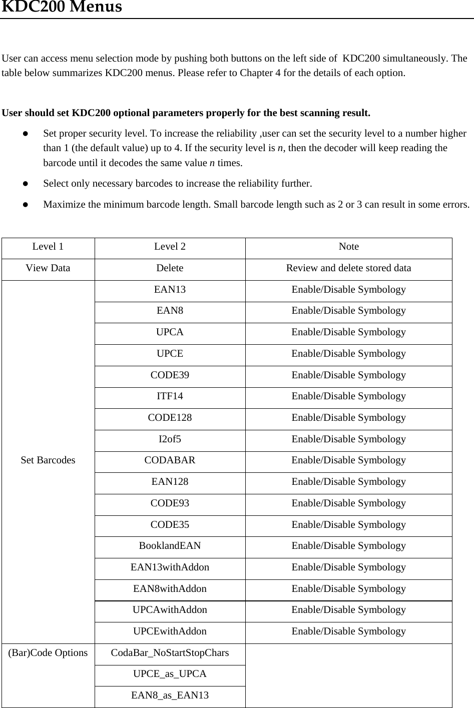
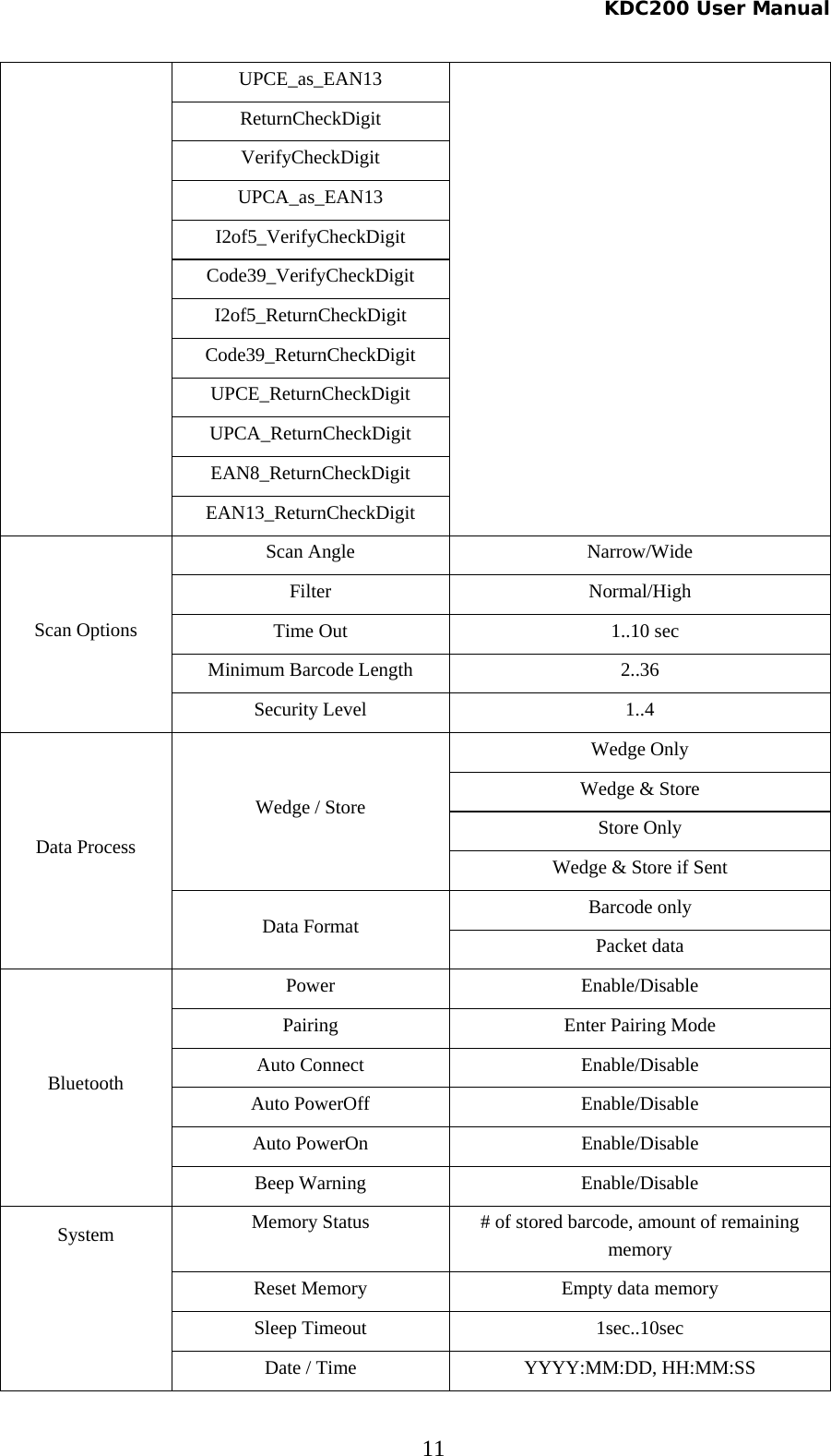
KDC200 User Manual
User manual
Navigation menu
Upload a User Manual
Namespaces
Wiki Guide
HTML
PDF
Info
Views
User Manual
Discussion / Help
Navigation