AISOLUTION KDCUHF05 KDCSLED UHF 0.5W Module Pack User Manual

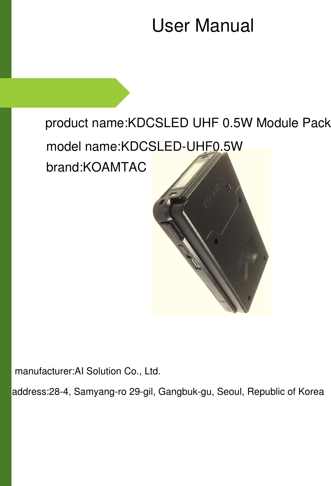
AISOLUTION CO., LTD. KDCSLED UHF 0.5W Module Pack

User manual

                                                                                                  User Manualproduct name:KDCSLED UHF 0.5W Module Packmodel name:KDCSLED-UHF0.5Wbrand:KOAMTACmanufacturer:AI Solution Co., Ltd.address:28-4, Samyang-ro 29-gil, Gangbuk-gu, Seoul, Republic of Korea
1  KOAMTAC, Inc. | 116 Village Blvd. Suite 305 | Princeton, NJ 08540 | phone 609.256.4700 | fax 609.228.4373 www.koamtac.com Table of Contents ➢ KDC470 UHF Module Concept ........................................................................................................................ 2 ➢ KDC470 UHF Module Assemble Instructions ................................................................................................... 3 .1 What’s in the box ....................................................................................................................................... 3 .2 How to assemble ....................................................................................................................................... 3 .3 How to use to read RFID tag ...................................................................................................................... 4 ➢ KDC470 UHF Module Configuration ................................................................................................................ 6 3.1 Read Mode (Barcode-reading mode vs. Tag-reading mode) .......................................................................... 6 3.2 Operation Mode (Single-reading mode vs. Multiple-reading mode) .............................................................. 6 3.3 Triggering Methods ...................................................................................................................................... 7 3.4 Timeout Value .............................................................................................................................................. 7 3.5 Data Types.................................................................................................................................................... 7 3.6 Data Format ................................................................................................................................................. 7 ➢ UHF Special Barcodes ..................................................................................................................................... 8
2  KOAMTAC, Inc. | 116 Village Blvd. Suite 305 | Princeton, NJ 08540 | phone 609.256.4700 | fax 609.228.4373 www.koamtac.com ➢ KDC470 UHF Module Concept  One of major features for KDC470 is modular design, which means various technologies can be attached on top of KDC as a module. UHF RFID Reader module (0.5W) is one of them. ➢ Product Spec KDC470 UHF module is fully compliant with ISO18000-6C/EPC Global Gen II reader protocol UHF Spec  UHF 0.5 Watt Standards Supported EPC Class1 Gen2, EPC Gen2 V2, ISO 18000-6c Antenna type/field  Rectangular Micro-Strip Ceramic Antenna(0dBic) Tx Output Power Range  +20 to +22dBm   Rx Sensitivity  -63dBm (@Tx 27dBm) Fastest read rate  150 Tags per second Nominal read range  1.5 meter Batch mode memory  409,600 RFID tags (EPC Data) Dimensions  Companion: 104.5 x 60 x 10 (mm) KDC470+Companion: 105 x 65 x 19 (mm) Weight  Companion: 53.5 gram KDC470+Companion: 134.5 gram Drop spec  5 feet (1.5m) Temp spec  Operating: -4˚F (-20˚C) ~ 122˚F (50˚C) Storage: -4˚F (-20˚C) ~ 140˚F (60˚C) Humidity spec  5% ~ 95% (noncondensing) Sealing  IP65 Compliance  KC, FCC, CE, TELEC
3  KOAMTAC, Inc. | 116 Village Blvd. Suite 305 | Princeton, NJ 08540 | phone 609.256.4700 | fax 609.228.4373 www.koamtac.com ➢ KDC470 UHF Module Assemble Instructions  .1 What’s in the box  • KDCSLED-UHF0.5W   • 4 screws + 1 extra                    .2 How to assemble  ➢ Use 4 screws to fasten UHF RFID module to KDC470
4  KOAMTAC, Inc. | 116 Village Blvd. Suite 305 | Princeton, NJ 08540 | phone 609.256.4700 | fax 609.228.4373 www.koamtac.com .3 How to use to read RFID tag  ➢ When you insert the battery, the power automatically turns on.   * The barcode- read mode is set immediately after the power is turned on.                     * Does not operate as UHF Reader.  ➢ Change to UHF Reader mode using mode change button.              * Press mode change button for 3 seconds to turn tag-reading mode on / off.       Mode Change Button   : On/Off tag-reading mode       Scan Button       : Barcode Read or Tag Read
5  KOAMTAC, Inc. | 116 Village Blvd. Suite 305 | Princeton, NJ 08540 | phone 609.256.4700 | fax 609.228.4373 www.koamtac.com ➢  Keep your arms straight and point the KDCSLED0.5W antenna towards the RFID tag and read the tag using the scan button.                           *  In order to transmit a UHF signal, you must press the scan button in tag-reading mode. * The UHF signal will not be transmitted unless the Scan button is pressed in the tag-reading mode  when worn on the body.  ➢ Hold the device as in the below picture.                        ➢ Please don’t cover an antenna as below picture.
6  KOAMTAC, Inc. | 116 Village Blvd. Suite 305 | Princeton, NJ 08540 | phone 609.256.4700 | fax 609.228.4373 www.koamtac.com ➢ For optimal UHF tag read performance and to be sure that human exposure to RF energy does not exceed the FCC, European Union guidelines, always follow below instructions and precautions: o Before using KDC470 UHF reader, user should carefully read this operation guide and user guide to understand how to use KDC470 UHF reader properly. o KDC470 UHF reader should be used by professional person who understand fully how to operate KDC470 UHF reader. o Maintain at least 20cm between KDC470 UHF reader and the body when reading UHF RFID tag. o Keep KDC470 UHF Antenna to face the UHF RFID tag, but not your body when reading UHF RFID tag. o Exit UHF tag read mode and keep Barcode read mode when finished reading UHF tag. o Don’t wear KDC470 UHF reader when not using KDC470 UHF reader. ➢ KDC470 UHF Module Configuration  3.1 Read Mode (Barcode-reading mode vs. Tag-reading mode) ➢ There are two read modes. One is barcode-reading mode (Barcode can be read by SCAN button) and the other one is tag-reading mode (UHF Tag can be read by SCAN button). ➢ After reset, KDC470 is set to a barcode-reading mode. ➢ The mode can be changed when you press and hold UP button for 3 seconds.  ➢ Or, the application can also change the mode between a barcode-reading mode and a tag-reading mode using SDK. ➢ When the mode is changed, 3 short beeps means a tag-reading mode. 1 long and 1 short beeps means a barcode-reading mode. 3.2 Operation Mode (Single-reading mode vs. Multiple-reading mode) ➢ KDC470 has two operation modes: Single-reading and Multiple-reading. ➢ Single-reading mode means it reads only one tag by triggering the SCAN button once. ➢ Multiple-reading mode means it reads multiple tags by triggering the SCAN button once. ➢ The mode can be changed by scanning the special barcodes below. (The default is a Multiple-reading mode). Single-reading Mode  Multiple-reading Mode   ➢ In the single-reading mode, it keeps trying to read any tag until timeout value is expired. Once it reads any tag, KDC470 sends the first read tag information to the host and stops reading. ➢ In the multiple-reading mode, KDC470 sends all the information of the tags which are read until timeout value is expired. ➢ The application can also change the mode between a single-reading mode and a multiple-reading mode using SDK.
7  KOAMTAC, Inc. | 116 Village Blvd. Suite 305 | Princeton, NJ 08540 | phone 609.256.4700 | fax 609.228.4373 www.koamtac.com 3.3 Triggering Methods ➢ There are two ways to read a UHF tag: Hardware-triggering and software-triggering. ➢ The hardware-triggering is done by a SCAN button and the software-triggering is done by an API called from an application using SDK.  3.4 Timeout Value ➢ KDC470 has UHF tag reading timeout value with the same with Barcode reading timeout value. The default timeout is a 2 second.   3.5 Data Types ➢ KDC470 only sends EPC data to a host by default but sends along with PC data if the user configures PC+EPC by reading the special barcode below.  Data Type – EPC  Data Type - PC+EPC   ➢ The data types can also be changed using SDK.  3.6 Data Format ➢ KDC470 sends tag data to a host with binary format by default and can be changed to HexaDecimal format by reading the special barcode below.  Data Format = Binary  Data Format = Hexa Decimal   ➢ The data format can also be changed using SDK.
8  KOAMTAC, Inc. | 116 Village Blvd. Suite 305 | Princeton, NJ 08540 | phone 609.256.4700 | fax 609.228.4373 www.koamtac.com ➢ UHF Special Barcodes   Enable UHF Power   Disable UHF Power   Power Level = 0  Power Level = 1  Power Level = 2  Power Level = 3  Power Level = 4  Power Level = 5  Power Level = 6  Power Level = 7  Data Format = Binary  Data Format = Hexa Decimal  Smart Hopping
FCC Statement 1. This device complies with Part 15 of the FCC Rules. Operation is subject to the following two conditions: (1) This device may not cause harmful interference. (2) This device must accept any interference received, including interference that may cause undesired operation. 2. Changes or modifications not expressly approved by the party responsible for compliance could void the user's authority to operate the equipment. NOTE:   This equipment has been tested and found to comply with the limits for a Class B digital device, pursuant to Part 15 of the FCC Rules. These limits are designed to provide reasonable protection against harmful interference in a residential installation. This equipment generates uses and can radiate radio frequency energy and, if not installed and used in accordance with the instructions, may cause harmful interference to radio communications. However, there is no guarantee that interference will not occur in a particular installation. If this equipment does cause harmful interference to radio or television reception, which can be determined by turning the equipment off and on, the user is encouraged to try to correct the interference by one or more of the following measures: Reorient or relocate the receiving antenna. Increase the separation between the equipment and receiver. Connect the equipment into an outlet on a circuit different from that to which the receiver is connected.   Consult the dealer or an experienced radio/TV technician for help.  SAR Information Statement Your Module Pack is a radio transmitter and receiver. It is designed and manufactured not to exceed the emission limits for exposure to radiofrequency (RF) energy set by the Federal Communications Commission of the U.S. Government. These limits are part of comprehensive guidelines and establish permitted levels of RF energy for the general population. The guidelines are based on standards that were developed by independent scientific organizations through periodic and thorough evaluation of scientific studies. The standards include a substantial safety margin designed to assure the safety of all persons, regardless of age and health. The exposure standard for Module Pack employs a unit of measurement known as the Specific Absorption Rate, or  SAR. The SAR limit set by the FCC is 4.0 W/kg. * Tests for SAR are conducted with the Module Pack transmitting at its highest certified power level in all tested frequency bands. Although the SAR is determined at the highest certified power level, the actual SAR level of the Module Pack while operating can be well below the maximum value. This is because the Module Pack is designed to operate at multiple power levels so as to use only the power required to reach the network. In general, the closer you are to a wireless base station antenna, the lower the power output. Before a Module Pack model is available for sale to the public, it must be tested and certified to the FCC that it does not exceed the limit established by the government adopted requirement for safe exposure. The tests are performed in positions and locations (e.g., at the ear and worn on the body) as required by the FCC for each model. The maximum scaled SAR in extremity mode is 3.074W/Kg. While there may be differences between the SAR levels of various  Module Pack and at various positions, they all meet the government requirement for safe exposure. The FCC has granted an Equipment Authorization for this model Module Pack with all reported SAR levels evaluated as in compliance with the FCC RFexposure guidelines. SAR information on this model Module Pack is on file with the FCC and can be found under the Display Grant section of http://www.fcc.gov/ oet/fccid after searching on   FCC ID:VH9KDCUHF05 Additional information on Specific Absorption Rates (SAR) can be found on the Cellular Telecommunications Industry Asso-ciation (CTIA) web-site at http://www.wow-com.com. * In the United States and Canada, the SAR limit for Module Pack used by the public is 1.6 watts/kg (W/kg) averaged over one gram of tissue. The standard incorporates  a sub-stantial margin of safety to give additional protection for the public and to account for any variations in measurements.  Body-worn Operation This device was tested for typical body-worn operations. To comply with RF exposure requirements, a minimum separation distance  of 0mm must be maintained between the user’s body and the handset, including the antenna. Third-party belt-clips, holsters,   and similar accessories used by this device should not contain any metallic components. Body-worn accessories that do not meet these requirements may not comply with RF exposure requirements and should be avoided. Use only the supplied or an approved

Navigation menu