AKG Acoustics DPT700 digital pocket transmitter for wireless microphones User Manual DMS700 BDA 2 EN3
AKG Acoustics GmbH digital pocket transmitter for wireless microphones DMS700 BDA 2 EN3
UserManual.wiki
>
AKG Acoustics
>
DPT700 User Manual
Users manual
Navigation menu
Upload a User Manual
Namespaces
Wiki Guide
HTML
PDF
Info
Views
User Manual
Discussion / Help
Navigation
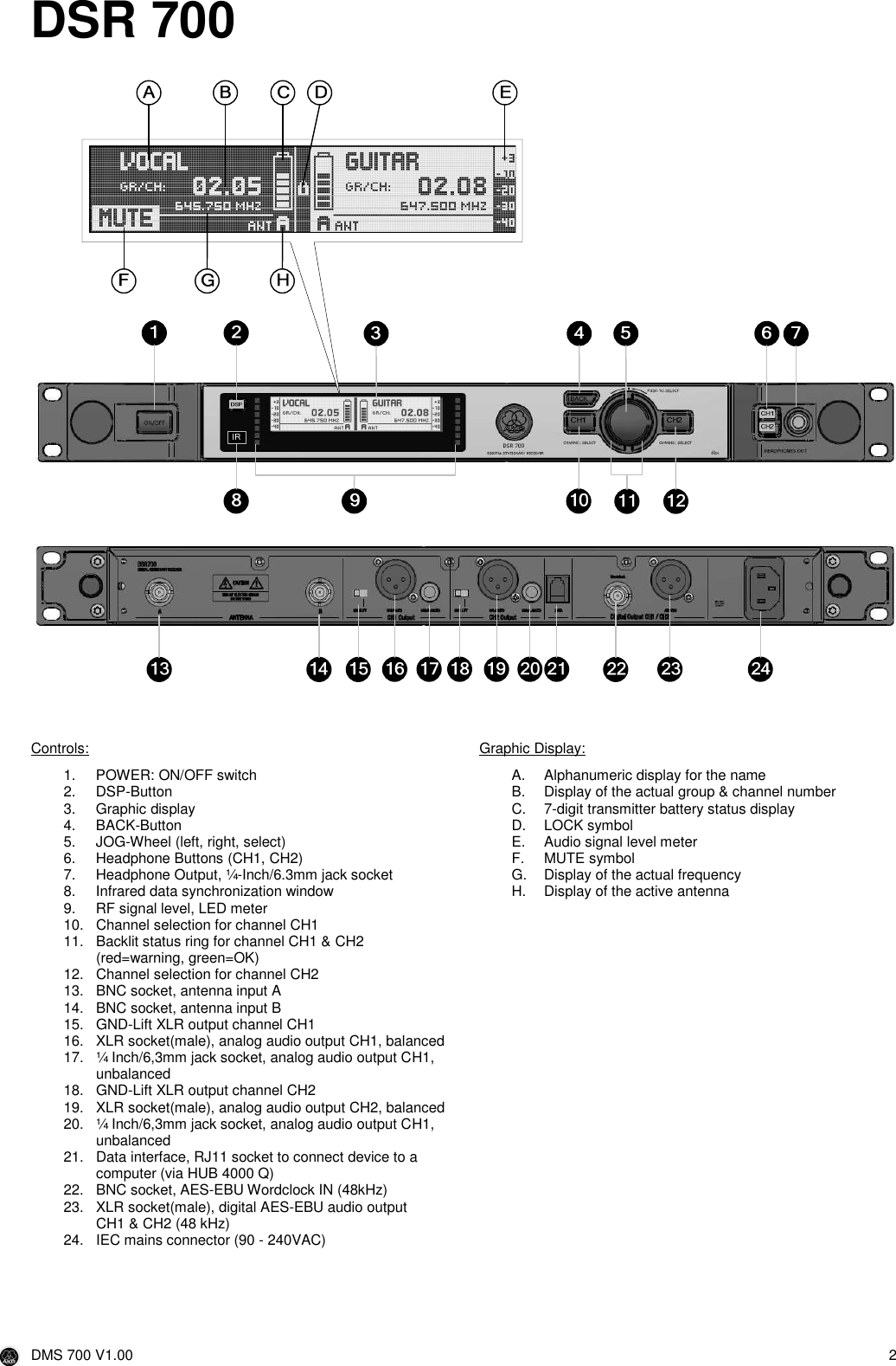
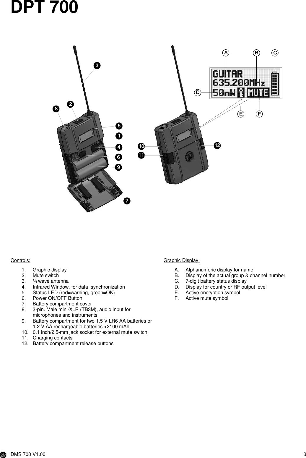
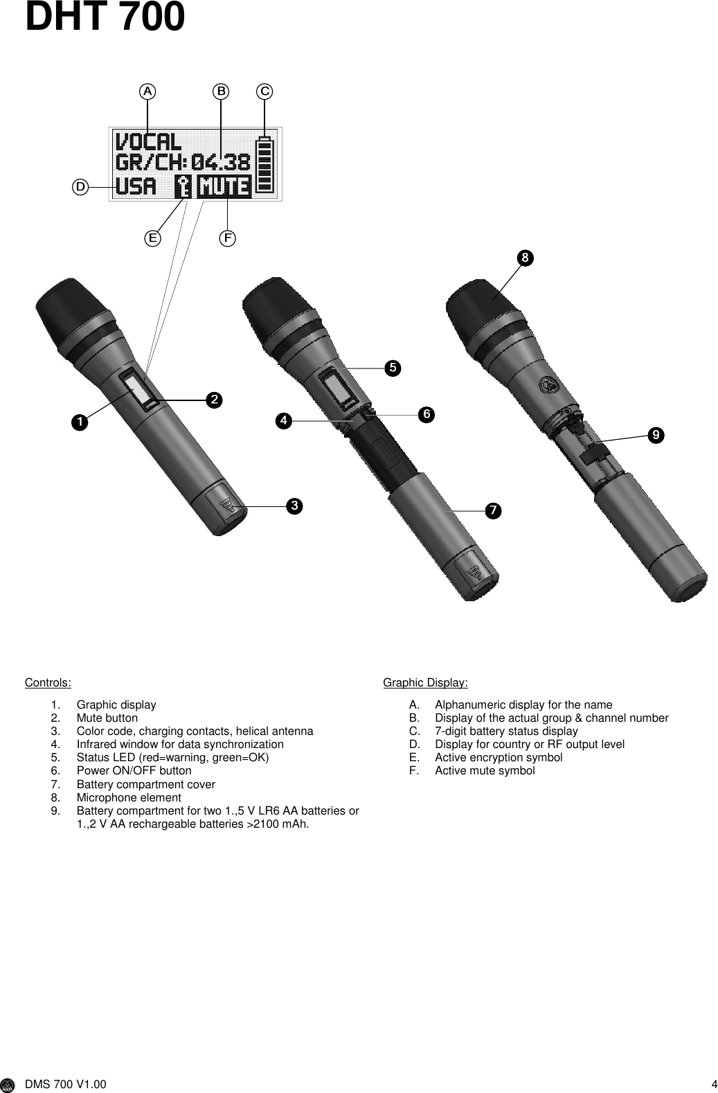
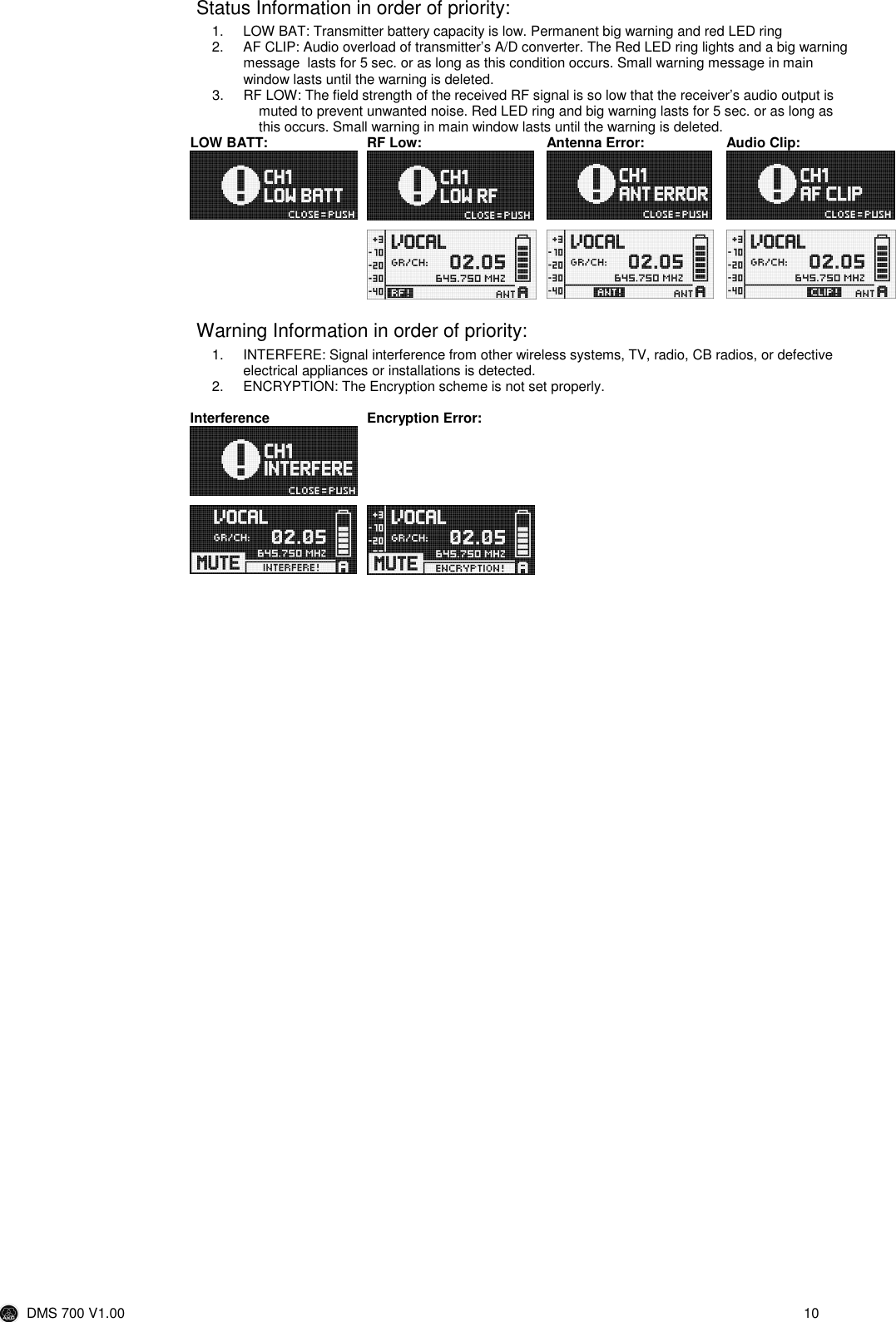
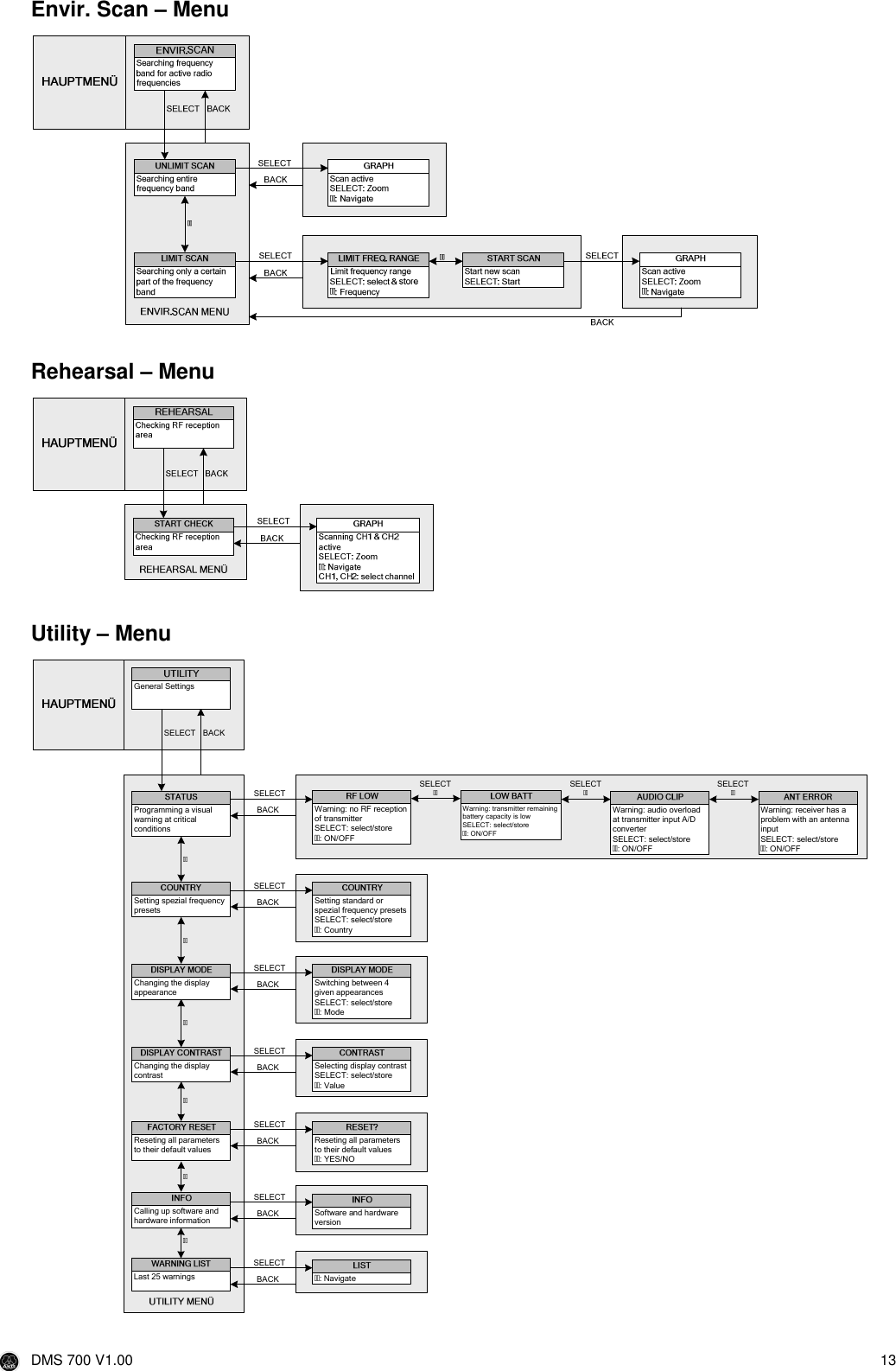
![DMS 700 V1.00 16 DSP Button The DSP button provides a bypass function for LOW CUT, EQ, COMPRESSOR and LIMITER for both channels separately. Output Gain For matching the receiver’s BALANCED output level to the input gain of the connected equipment . If you are using the MIC input of your mixer, the LINE 0 dB level might overload the input. In that case, set the receiver’s output gain to MIC -30 dB to reduce the output level. The UNBALANCED line output level is not adjustable Environment Scan The Environment Scan function converts the receiver into a spectrum analyzer. The UNLIMITED SCAN automatically searches the receiver's entire frequency band ±6 MHz for active radio frequencies. The LIMIT SCAN provides the possibility of scanning only a part of the receiver’s frequency range. During the search, the audio output is muted and the display shows a frequency graph. You can navigate (CW, CCW) and zoom (push) through the graph by using the SETUP Wheel. Rehearsal – Sound Check The Rehearsal Scan function converts the receiver to an RF recorder to check the RF level in your reception area. Start this function and walk around the desired coverage area with the synchronized transmitter. The graphic display shows you the received signal level in time. To mark some positions, you can use the transmitter MUTE button to set markers on the receiver display. You can navigate (CW, CCW) and zoom (push) through the graph by using the SETUP Wheel. The received signal level should never drop below -85 dBm. You can optimize signal reception by changing the position of the connected antennas. DSP Profile - Factory default valuesLow Cut LimiterNo. Profil Display User Input Gain [dB]Freq. [Hz]Low [dB]Mid [dB]MidFreq [kHz]High [dB]Threshold [dB]Ratio Gain [dB]Attack [ms]Release [ms]Threshold [dB]1Handheld Present HT 20 77 0 0 1.0 3.0 -30 2.1:1 3 1 712Headset Present PT 25 40 -25 1.5:1 5 6 2073C555L Present C555 15 40 -25 1.5:1 5 6 2074Handheld Music HT 105Headset Music PT 206C555L Music C555 107Instrument Microphone mit BodypackInstru PT Profi+Amateure, Trompete, Tuba, Drums 208Guitar mit BodypackGuitar PT E-Gitarre, Bassgitarre,aktive Akustikgitarre 0Equalizer CompressorPresenterAmateure, Powerpoint, Kirche, Ansprache 0OFFMusicProfi, SängerIn Rockband, Karaoke, Musical40 OFF OFF 99PT InstrumentOFF OFF OFF](https://usermanual.wiki/AKG-Acoustics/DPT700/User-Guide-1055868-Page-16.png)