ALCON Telecommunications 5801A01 Wireless LAN Outdoor Bridge User Manual
ALCON Telecommunications Co., Ltd. Wireless LAN Outdoor Bridge
Users Manual
ALink-5801a Wireless LAN Outdoor Bridge
ALCON Telecommunications Co., Ltd. 1
ALink-5801a
Wireless LAN Outdoor Bridge
User’s Manual
Version 3.2a
April. 10, 2005

ALink-5801a Wireless LAN Outdoor Bridge
ALCON Telecommunications Co., Ltd. 2
PREVIOUS HISTORY
Revision Date of Issue Scope
0.0 March 31, 2004 Initial
1.0 April 2, 2004 First draft
2.0 A p r i l 2 , 2 0 0 4 Correct errors and the paragraph
orders
2.5 May 25, 2004 Second draft
3.0 June 15, 2004 Edit the third part and correct
errors
3.1a Dec. 30, 2004
A
dd the third part and correct
errors
3.2a April. 10,2005 Correct errors and add feature

ALink-5801a Wireless LAN Outdoor Bridge
ALCON Telecommunications Co., Ltd. 3
Federal Communication Commission Interference Statement
This equipment has been tested and found to comply with the limits for a Class B digital device,
pursuant to Part 15 of the FCC Rules. These limits are designed to provide reasonable
protection against harmful interference in a residential installation. This equipment generates,
uses and can radiate radio frequency energy and, if not installed and used in accordance with
the instructions, may cause harmful interference to radio communications. However, there is
no guarantee that interference will not occur in a particular installation. If this equipment does
cause harmful interference to radio or television reception, which can be determined by turning
the equipment off and on, the user is encouraged to try to correct the interference by one of the
following measures:
Reorient or relocate the receiving antenna.
Increase the separation between the equipment and receiver.
Connect the equipment into an outlet on a circuit different from that to which the receiver is
connected.
Consult the dealer or an experienced radio/TV technician for help.
FCC Caution: Any changes or modifications not expressly approved by the party responsible for
compliance could void the user's authority to operate this equipment.
This device complies with Part 15 of the FCC Rules. Operation is subject to the following two
conditions: (1) This device may not cause harmful interference, and (2) this device must accept
any interference received, including interference that may cause undesired operation.
This device and its antenna(s) must not be co-located or operating in conjunction with any other
antenna or transmitter.
IMPORTANT NOTE:
FCC Radiation Exposure Statement:
This equipment complies with FCC radiation exposure limits set forth for an uncontrolled
environment. This equipment should be installed and operated with minimum distance 20cm
between the radiator & your body.
ALink-5801a Wireless LAN Outdoor Bridge
ALCON Telecommunications Co., Ltd. 4
PREFACE
The ALCON Telecommunications Co., Ltd. (ALCON) is so honored to offer you this
product – “ALink-5801a Wireless LAN Outdoor Bridge”. The ALink-5801a Wireless LAN
Outdoor Bridge is cost-effective to expand or relocate your local wired networks (LANs). This
advanced design suits the goal to create an unwired working environment.
The ALink-5801a with IEEE 802.11a feature is the wireless solution for building-to-building.
The ALink-5801a provides the data rate up to 54 Mbps and is suited for enterprises, campus or
off-site locations that require LAN or Internet access without the availability of wired networks to
extend network coverage.
The ALink-5801a provides point-to-point and point-to-multi-point connection capabilities.
The wireless building-to-building bridging solution contains a state-of-the-art wireless Bridge,
high gain performance antenna and power-over-Ethernet technology. For further protection,
the bridge and power-over-Ethernet adapter have built in lightning protector.
The ALink-5801a provides the alternative solution for last-mile connection. By leveraging
the IEEE 802.11’s volume power and low cost, ALink-5801a Link provides very cost effective
solution to carriers. With the cost effective wireless last mile solution, service provider can
have fast deployment (time-to-market) and successful business models.
The document is for your information to know more detail about ALCON ALink-5801a
Weather proof Wireless LAN Outdoor Bridge. We will introduce the hardware part, the
software configuration, and the field installation in the following chapters. This manual is
intended for those people who will install and operate the ALCON ALink-5801a.
ALCON Telecommunications Co., Ltd..
April. / 2005
ALink-5801a Wireless LAN Outdoor Bridge
ALCON Telecommunications Co., Ltd. 5
Table of contents
PREVIOUS HISTORY................................................................................................................................................ 2
PREFACE ............................................................................................................................................................... 4
TABLE OF CONTENTS............................................................................................................................................ 5
TABLE OF CONTENTS............................................................................................................................................ 7
MANUAL CONVENTIONS.......................................................................................................................................... 8
DISCLAIMER........................................................................................................................................................... 9
1. INTRODUCTION ................................................................................................................................................. 10
2. ALINK-5801A HARDWARE FEATURE ............................................................................................................. 10
2.1 HARDWARE OUTLINE...................................................................................................................................... 10
2.2 HARDWARE ARCHITECTURE............................................................................................................................ 11
2.3 PRODUCT FEATURE........................................................................................................................................ 12
2.4 PRODUCT AND ACCESSORIES ......................................................................................................................... 12
2.5 PRODUCT CONNECTION FEATURE................................................................................................................... 13
2.5.1 External Antenna & Power over Ethernet (PoE) Cable Connector..................................................... 13
2.5.2 Grounding Screw ................................................................................................................................ 13
2.5.3 Caution over Cable Connection.......................................................................................................... 13
2.6 PRODUCT WARRANTY .................................................................................................................................... 14
2.7 WARRANTY LIMITATION .................................................................................................................................. 14
2.8 REQUIREMENT ............................................................................................................................................... 14
2.9 FEATURE SUMMARY ....................................................................................................................................... 15
3. IP DISCOVER UTILITY....................................................................................................................................... 16
4. BRIDGE (ALINK-5801A) CONFIGURATION..................................................................................................... 18
4.1 THE MASTER/SLAVE SIDE PC NETWORK CONFIGURATION ............................................................................... 18
4.1.1 How To Start Network Configuration on your PC ............................................................................... 18
4.1.2 Master Bridge side PC TCP/ IP Setup................................................................................................ 19
4.1.2.1 Master side PC TCP/IP Setup.....................................................................................................................19
4.1.2.2 Master Bridge Side PC IP/ MAC Address Set up ........................................................................................19
4.1.2.3 Slave Side PC Configuration and TCP/IP set up.........................................................................................20
4.1.3 MASTER/SLAVE BRIDGE CONFIGURATION..................................................................................................... 21
4.1.3.1 How To Start .................................................................................................................................... 21
4.1.3.2 Master/Slave Bridge Configuration .................................................................................................. 22
4.1.3.2.1 After Login................................................................................................................................................22
4.1.3.2.2 Region/Country Set up.............................................................................................................................22
4.1.3.2.3 Master/ Slave side IP/ MAC Address first time Set up..............................................................................24
4.1.3.2.3 Configure 5GHz Bridge Setting ................................................................................................................25
Radio Setting...................................................................................................................................................25
Security Setting – Master / Slave side Share/Unique Key...........................................................................28
Master Side......................................................................................................................................................29
Slave Side........................................................................................................................................................30
4.1.4.2 Master & Slave Bridge joining condition......................................................................................................31
4.1.4.3 Statistics......................................................................................................................................................31
4.2 FIRMWARE AND LICENSE UPGRADE................................................................................................................. 34
4.3 REBOOTING ................................................................................................................................................... 35
5. SNMP .................................................................................................................................................................. 36
6. PLANNING LINKAGE......................................................................................................................................... 40
6.1 SITE SURVEY ................................................................................................................................................. 40
6.2 DATA RATE.................................................................................................................................................... 41
6.3 PLANNING RADIO PATH .................................................................................................................................. 41
6.3.1 Antenna Height ................................................................................................................................... 43
6.3.2 Antenna Types.................................................................................................................................... 44
6.3.3 Antenna Cable .................................................................................................................................... 44
6.3.4 Weather Affection................................................................................................................................ 45
ALink-5801a Wireless LAN Outdoor Bridge
ALCON Telecommunications Co., Ltd. 6
7 FIELD INSTALLATION........................................................................................................................................ 46
7.1 UNPACK THE SHIPMENT .................................................................................................................................. 46
7.1.1 Required Tools:................................................................................................................................... 46
7.1.2 Product................................................................................................................................................ 46
7.1.3 Accessories......................................................................................................................................... 46
7.2 INSTALLING THE ODU..................................................................................................................................... 47
7.2.1 Required Tools:................................................................................................................................... 47
7.2.2 Installed Accessories: ......................................................................................................................... 47
7.2.3 How to Mount the Bridge: ................................................................................................................... 47
7.2.4 Connecting the cable .......................................................................................................................... 48
7.2.5 General Antenna and Safety Tips....................................................................................................... 48
7.2.6 Basic Antenna Alignment.................................................................................................................... 49
7.2.7 ESD Protection.................................................................................................................................... 49
7.2.8 Review the Installation ........................................................................................................................ 49
APPENDIX A........................................................................................................................................................... 50
GLOSSARY........................................................................................................................................................... 50
APPENDIX B........................................................................................................................................................... 52
TROUBLESHOOTING.............................................................................................................................................. 52

ALink-5801a Wireless LAN Outdoor Bridge
ALCON Telecommunications Co., Ltd. 7
Table of contents
Picture1 Bridge outlook 11
Picture2 Bridge Architecture 11
Picture 3 Bridge 13
Picture 4 Connection1 13
Picture 5 IP Discover Tool 16
Picture 6 Find out the IP and MAC address 17
Picture 7 Start Menu 18
Picture 8 Network Connection 18
Picture 9 Local Area Connection Properties 19
Picture 10 Internet Protocol Properties 20
Picture 11 Enter Username and Password 21
Picture 12 Statistic Page 22
Picture 13 Region/Country Setup 23
Picture 14 Manually setup IP address 24
Picture 15 Auto Get IP 25
Picture 16 5GHz Bridge (Master) 28
Picture 17 5GHz Bridge (Slave) 28
Picture 18 Master Bridge Security Setup 29
Picture 19 Slave Bridge Security Setup 30
Picture 20 Master/Slave Bridges Connections 31
Picture 21 Statistics 32
Picture 22 Firmware Upload Web Page 34
Note: In case network interruption happens during firmware
uploading, system will still keep on current active firmware. You
may perform the firmware upgrade again when network is back to
normal. 34
Picture 23 Rebooting Window 35
Table 1 Evaluated Maximum Distance 41
Picture 24 Line-of-Sight (LOS) 42
Table 2 Estimated LOS Clearance 43
Picture 25 Antenna Height 43
Picture 26 The Bridge with the omnidirectional antenna 44
Picture 27 Mount the ODU on the Mask or the Pole 47

ALink-5801a Wireless LAN Outdoor Bridge
ALCON Telecommunications Co., Ltd. 8
MANUAL CONVENTIONS
Bold Bold type within paragraph text indicates commands, file names,
directory names, paths, output, or returned values.
Italic Within commands, italics indicate a variable that the user must
specify.
Titles of manuals or other published documents are also set in
italics.
Courier The courier font indicates output or display.
[] Within commands, items enclosed in square brackets are
optional parameters or values that the user can choose to specify
or omit.
{} Within commands, item enclosed in braces are options from
which the user must choose.
| Within commands, the vertical bar separates options.
… An ellipsis indicates a repetition of preceding parameter.
> The right angle bracket separates successive menu selection.
NOTE: This message denotes neutral or positive information that calls out important points
to the text. A note provides information that applies only in special cases.
Caution: Cautions call special attention to hazards that can cause system damage
or data corruption, to a lesser degree than warnings.
Warnings: Warnings call special attention to hazards that can cause system
damage, data corruption, personal injury, or death.
ALink-5801a Wireless LAN Outdoor Bridge
ALCON Telecommunications Co., Ltd. 9
DISCLAIMER
The ALCON ALink-5801a Wireless LAN Outdoor Bridge User Manual
Document No.: 50-5000(REV: 3.2a), April. 10, 2005.
COPYRIGHT © 2005 ALCON Telecommunications Co., Ltd.
ALL RIGHTS RESERVED
Any part of this publication could not be copied, stored in a retrieval system, or translated into
any language or computer language in any form or any means, electronic, magnetic, chemical,
manual or otherwise, without the prior written permission of ALCON Telecommunications Co.,
Ltd. (ALCON). 2F, No.480-5,Sec.6, Yen-Ping N. Road Shih-Lin, Taipei, Taiwan, 111
The ALCON ALink-5801a is a registered trademark of ALCON Telecommunications Co.,
Ltd.
Printed in the Taiwan
The instructions in this manual have been carefully checked for accuracy and are presumed to
be reliable. The accuracy and adequacy of this document are the responsibilities of ALCON
Telecommunications Co., Ltd. Please, give us any comments or corrections to ALCON
Telecommunications Co., Ltd.
ALink-5801a Wireless LAN Outdoor Bridge
ALCON Telecommunications Co., Ltd. 10
1. Introduction
The ALink-5801a is designed for the outdoor environment. It will function under the strict
weather as the following passages you see. About the further protection, the bridge and
Power over Ethernet adapter are built with the lightning protector. This advanced innovation is
to help you to increase from the productivity, cost-effective, mobile Internet access, to other
sections.
The ALink-5801a is a wireless building-to-building bridge solution. The ALink-5801a
provides the data rate up to 54 Mbps that is best suited for enterprises, campus or off-site
locations that require LAN or Internet access without the availability of wired networks to extend
the network coverage. The ALink-5801a provides the point to point and point to multi-point
connection.
One of the ALink-5801a advanced feature is over the data rate section. The bridge has
one data rate mode, the one is the IEEE 802.11a. About the bridge under the IEEE 802.11a
mode, it supports the data rate from 6 Mbps to 54 Mbps. The supported frequency channel for
the IEEE802.11a is across from 5.725 to 5.850 GHz.
Another advanced design is the security setting. We all know the security is the major issue
over the wireless communication. We offer the two modes on the security setting, one is
“Shared Key”, and the other is “Unique Key”. It is really easy for you to secure your
communication through this thoughtful feature.
About the field installation, it is easy for you to install the device outside field. The
following paragraphs remind you what you need to notice during the installation form the site
survey, antenna installation, to the ODU installation. We also offer you the evaluated max
distance as your reference under the IEEE802.11a and the Antenna gain is 12 dBi .
During the appendix section, we offer you some terminologies explanation and how to do
the simple troubleshooting when you encounter the difficult over the wireless connection.
ALCON Telecommunications Co., Ltd.
April / 2005
2. ALink-5801a Hardware FEATURE
2.1 Hardware Outline
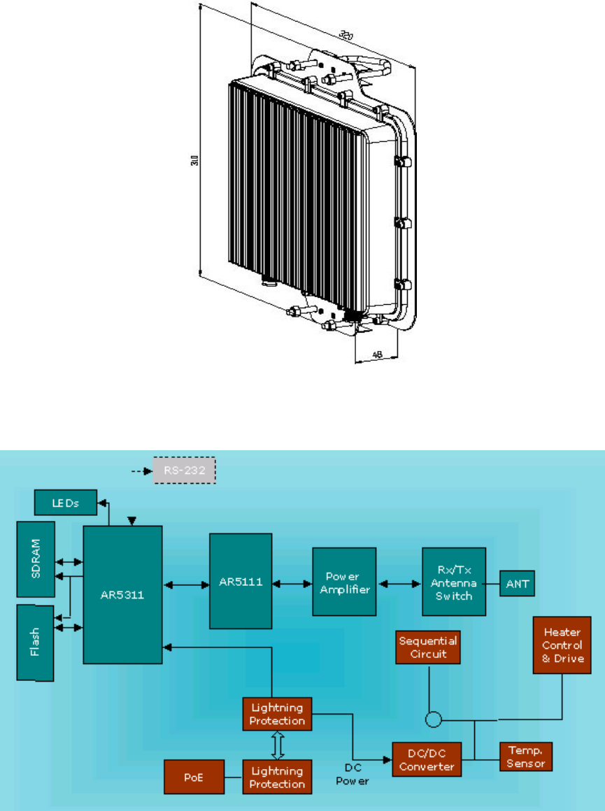
ALink-5801a Wireless LAN Outdoor Bridge
ALCON Telecommunications Co., Ltd. 11
Picture1 Bridge outlook
2.2 Hardware Architecture
Picture2 Bridge Architecture
ALink-5801a Wireless LAN Outdoor Bridge
ALCON Telecommunications Co., Ltd. 12
2.3 Product Feature
Temperature — The wireless bridge is tested for normal operation in temperatures
from -33°C to 55°C. Operating in temperatures outside of this range may cause the
unit to fail.
Wind Velocity — The wireless bridge can operate in winds up to 90 MPH and survive
higher wind speeds up to 125 MPH. You must consider the known maximum wind
velocity and direction at the site and be sure that any supporting structure, such as a
pole, mast, or tower, is built to withstand this force.
Lightning — The wireless bridge includes its own built-in lightning protection.
However, you should make sure that the unit, any supporting structure, and cables are
all properly grounded. Additional protection using lightning rods, lightning arrestors,
or surge suppressors may also be employed.
Range —The wireless bridge has been refined and optimized for long range
application, up to 28Km under the Basic data mode.
Rain — The wireless bridge is weatherproofed against rain and prolonged heavy rain
has no significant effect on the radio signal. You may need to use the sealing tape
around the Ethernet port connector for extra protection. If moisture enters the
connector, it may cause degradation in performance or even a complete failure of the
link.
2.4 Product and Accessories
A. ALink-5801a Master/Slave Bridge
B. CAT5/25M-RJ45 ( PoE Cable )
C. DC Injector /RJ45 (RJ45DI-48)
D. N-Type to N-Type RG-400/1.5M cable
E. AC/DC Power Supply (DC48V 1.37A)
F. Installation Guide
G. Utility and User’s Manual CD
H. Installation kits
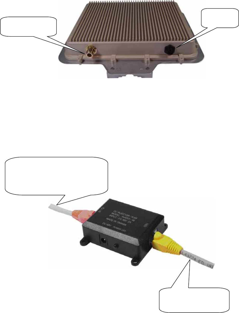
ALink-5801a Wireless LAN Outdoor Bridge
ALCON Telecommunications Co., Ltd. 13
2.5 Product Connection Feature
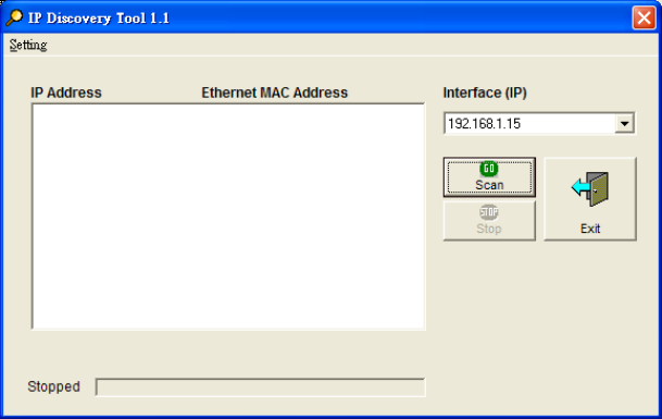
2.5.1 External Antenna & Power over Ethernet (PoE) Cable Connector
Picture 3 Bridge
2.5.2 Grounding Screw
1) Be grounding strip connection.
2) Proper grounding is always for the safety consideration.
2.5.3 Caution over Cable Connection
Picture 4 Connection1
External Antenna
Connector
PoE Cable
Connector
(1) Crossover Ethernet cable connects to
Input port and link to host PC.
(2) Straight Ethernet cable connects to
Input port and link to LAN Device
(
ex. Switch or Hub
)
cross ove
r
PoE Ethernet Cable
connect to Output port and
link to Bridge
ALink-5801a Wireless LAN Outdoor Bridge
ALCON Telecommunications Co., Ltd. 14
2.6 Product Warranty
This ALCON Telecommunications Co., Ltd. product is warranted against defects in
materials and workmanship for a period of one year from date of shipment. During the
warranty period time, the ALCON will either repair or replace products which to be defective.
For warranty service or repair, this product must be returned to a service facility designated
by ALCON. Buyer shall prepay shipping charges to ALCON and ALCON shall pay shipping
charges to return the product to Buyer. However, buyers shall pay all shipping charges, duties,
and taxes for products returned to ALCON from another country.
The ALCON warranty is for its software and the ALCON designed firmware when you
properly installed on this product. The ALCON does not warrant that the operation of the
product, or software, or firmware will be uninterrupted or error free.
2.7 Warranty Limitation
The foregoing warranty shall not apply to defects resulting from improper or inadequate
maintenance by buyers, buyer-supplied software, interfacing, unauthorized modification,
inappropriately use, operation out of the product environment specifications, or improper site
preparation and maintenance.
No any other warranty is expressed or implied. The ALCON specifically disclaims the
implied warranties of merchantability and fitness for a particular purpose.
2.8 Requirement
An FTP server is required for update bridge firmware.
The Ethernet connection is required for the initial Bridge configuration.
ALink-5801a Wireless LAN Outdoor Bridge
ALCON Telecommunications Co., Ltd. 15
2.9 Feature Summary
Provide the Ethernet to Wireless LAN Bridge fully compatible on IEEE 802.3 Ethernet
side and fully interoperable with IEEE 802.11a compliant equipments.
The Ethernet interface with 10 /100Base-T.
The operating mode is for IEEE 802.11a infrastructure.
The dynamic data rate switching with 6, 9, 1 2, 18, 24, 36, 48, 54 provided by Atheros
Chip allows auto fallback data rate for optimized reliability, throughput and transmission
range.
Using the FTP to upgrade the Firmware.
The 12dBi directional flat panel antenna offers up to 20 km transmission range with the
6MHz data rate.
The lightning protector.
Outdoor environment.
ALink-5801a Wireless LAN Outdoor Bridge
ALCON Telecommunications Co., Ltd. 16
3. IP Discover Utility
A simple Windows Utility is supplied on the CD. This utility can be used to locate the IP address
of the ALink-5801a Outdoor Bridge on the same sub-network segment. Although the
ALink-5801a Outdoor Bridge has a default IP address, this utility useful when the network
administrator forgets the modified IP address. Before using this utility, please make sure the
system firewall installed in your PC is “Disable”.
Below the installation and usage procedure:
1. Insert the Utility and User’s Manual CD into the CD-ROM drive.
2. Once the menu screen appears, click on the “IP Discover Tool” for installation. If the menu
screen dose not appears, enter E:\Utility\setup.exe (Assume “E” is your CD-ROM drive).
Flow the prompts to complete the installation.
3. After the installation completes, you can start this utility from “Start”>”Program
Files”>”IpDiscover1.1”>”IpDiscover1.1”.
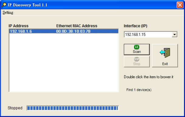
4. Once the utility is executed, the below screen will pop up. The “Interface(IP)” shows the
current IP address of your computer.
Picture 5 IP Discover Tool
ALink-5801a Wireless LAN Outdoor Bridge
ALCON Telecommunications Co., Ltd. 17
5. Click on the “Scan” button for the utility to start searching. And the utility will display the IP
address and MAC address of the available ALink-5801a Outdoor Bridge. Now you can using
a web browser to access the management interface with the IP address.
Picture 6 Find out the IP and MAC address
ALink-5801a Wireless LAN Outdoor Bridge
ALCON Telecommunications Co., Ltd. 18
4. Bridge (ALink-5801a) Configuration
4.1 The Master/Slave side PC Network Configuration
4.1.1 How To Start Network Configuration on your PC
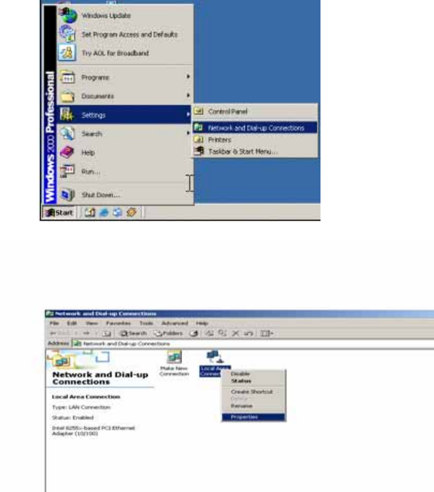
1) Click the “Start Menu” and choose “Setting”.
2) Click “Network and Dial-up Connection”.
3) Right-click on the “Local Area Connection” and select “properties”.
Picture 7 Start Menu
Picture 8 Network Connection
ALink-5801a Wireless LAN Outdoor Bridge
ALCON Telecommunications Co., Ltd. 19
4.1.2 Master Bridge side PC TCP/ IP Setup
4.1.2.1 Master side PC TCP/IP Setup
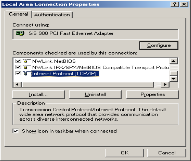
1) After clicking on “Property”, you will see the diagram as below.
2) Marking the “Internet Protocol (TCP/IP)” and click the “Properties”
Picture 9 Local Area Connection Properties
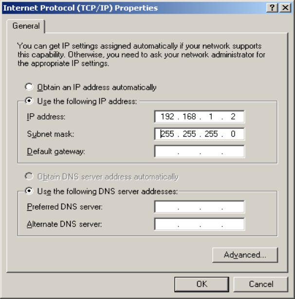
4.1.2.2 Master Bridge Side PC IP/ MAC Address Set up
1) Use “IP address (ex. 192.168.1.2)” under the same Bridge subnet and
Bridge Default IP Address( 192.168.1.20 ).
2) Using the default Subnet Mask Setting During the first time.
(Default value: 255.255.255.0)
3) Keep the “Default Gateway” as “Blank”.
4) Keep the “DNS Server Address” as “Blank” also.
5) Click ”OK” when you finish setting and Close the Window.
ALink-5801a Wireless LAN Outdoor Bridge
ALCON Telecommunications Co., Ltd. 20
Picture 10 Internet Protocol Properties
4.1.2.3 Slave Side PC Configuration and TCP/IP set up
1) About “ the Salve side PC Configuration “, you just following “the
same Set up method” as how you set the Master side.
2) As TCP/IP, you also follow “the exactly same procedure” as you set
up the Master side PC.
ALink-5801a Wireless LAN Outdoor Bridge
ALCON Telecommunications Co., Ltd. 21
4.1.3 Master/Slave Bridge Configuration
4.1.3.1 How To Start
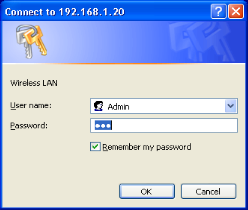
1) Launch a Web Browser.
2) Key in the default IP Address as URL (Default IP Address is http:// 192.168.1.20).
3) “Enter Network Password” Diagram will appear.
4) Enter “Username: Admin”(Case Sensitive).
5) Enter ”Password: 5up” (Case Sensitive).
6) Click ” OK ” when you finish.
Picture 11 Enter Username and Password
ALink-5801a Wireless LAN Outdoor Bridge
ALCON Telecommunications Co., Ltd. 22
4.1.3.2 Master/Slave Bridge Configuration
4.1.3.2.1 After Login
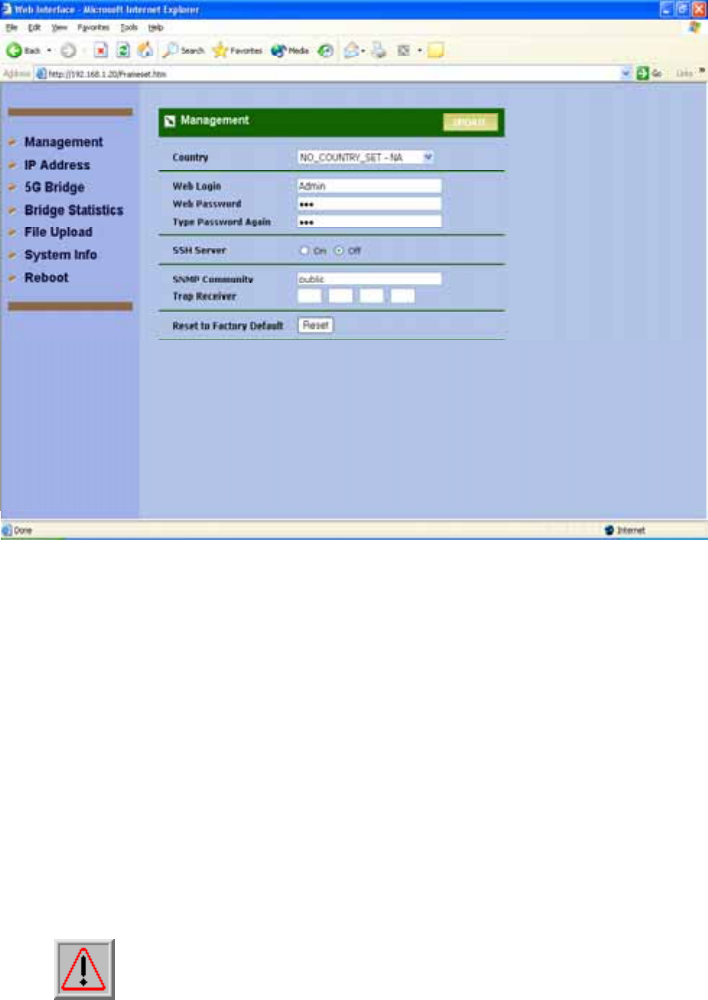
You will access by clicking the “Management” from left side menu.
Picture 12 Statistic Page
4.1.3.2.2 Region/Country Set up
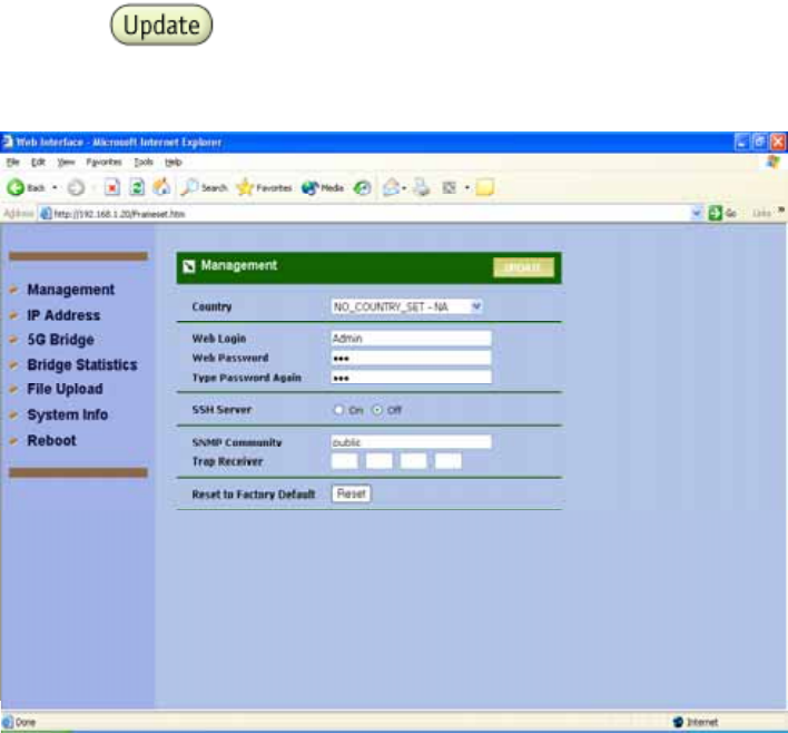
1) Click the “Management” on the left side of the Web page.
2) Select the “ Country ” you want from the list. Why you need to select the
“Country or Region” is because “different countries have its own RF
regulation”.
3) You need to use “the default Username and Password” when you sign in for
the first time.
4) SSH Server SSH is a secured telnet-like mechanism to invoke the command
line interface. All the commands and response will be encrypted. SSH
function can co-exist with Telnet function. The SSH port is 22. You need to
have an SSH client (e.g. OpenSSL) to access SSH.
Note: The web browser needs to equip 128-bit Cipher Strength to
process HTTPS SSL encryption. So, it is strongly
recommended you use the web browser whose version newer
than or equal to IE (Internet Explorer) 6 SP1 or Netscape 7.
Otherwise, you might experience the response of "The Page
Cannot Be Displayed".
5) SNMP Community Community name is a string for administrator to read the
ALink-5801a Wireless LAN Outdoor Bridge
ALCON Telecommunications Co., Ltd. 23
SNMP MIB from external SNMP manager. The default SNMP community
name is “public”. You may change the community name here as your plan.
6) Trap Receiver Trap is the notification of certain events generated by SNMP
agent to send to the network management server. To have the Outdoor
WLAN product send SNMP trap, you need to enter the IP address of the
server where the trap is sent to.
There are two trap messages, "Cold Start" and "Link Up", are supported.
They are sent out when the system is started.
7) Reset to Factory Default Press this button to reset to factory default.
8) Click and “ Reboot ” when you finish setting up.
Picture 13 Region/Country Setup
ALink-5801a Wireless LAN Outdoor Bridge
ALCON Telecommunications Co., Ltd. 24
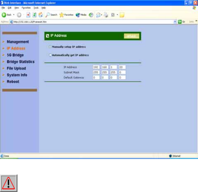
4.1.3.2.3 Master/ Slave side IP/ MAC Address first time Set up
1) “ Bridge Default IP Address (192.168.1.20) ” to do the first time set up and
you could change the IP Address you have after signing.
2) “Default value (255.255.255.0)” for the first time set up.
3) Keep the “Default Gateway” as “Blank” or set it up if you have your own
“Default Gateway”.
Picture 14 Manually setup IP address
Note: that every radio in the same network must be assigned a unique IP
address. So, you may need to have a network plan before deployment. Enter
the IP address, Subnet Mask and Gateway Address according to the planning. If
there is no gateway in the network, you may leave it all zeros.
ALink-5801a Wireless LAN Outdoor Bridge
ALCON Telecommunications Co., Ltd. 25
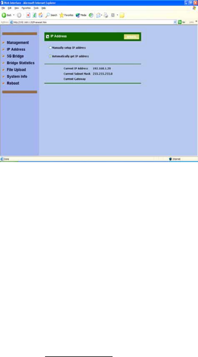
Picture 15 Auto Get IP
This will get the IP address from DHCP server if you have DHCP server enable in
your subnet.
4.1.3.2.3 Configure 5GHz Bridge Setting
Radio Setting
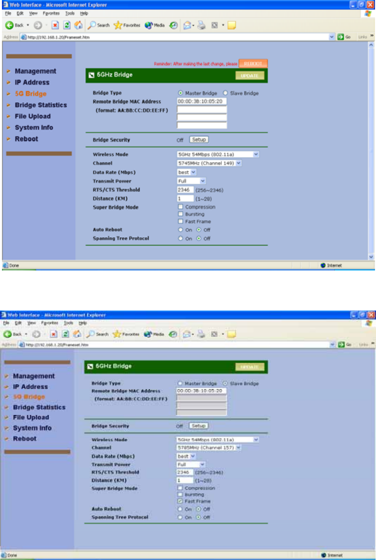
1) Bridge Type If the application is only for “Point to Point” architecture, the
set it as Slave one on each side. If the intended configuration is for “Point to
Multipoint” network architecture, you need one bridge loaded with Master
Bridge as host to wireless connect with the multiple remote bridges loaded
with Slave Bridge(s).
2) Remote Bridge MAC Address In order to establish the wireless link
between bridge radios, the MAC address of remotes bridge(s) need to be
registered in the address table. Type the MAC address with format
xx:xx:xx:xx:xx:xx (x is the hexadecimal digit) and use “Add” and “Delete”
button to edit the address table. A Master Bridge Radio may accommodate
up to 4 remote MAC addresses.
3) Bridge Security Please refer to “Bridge Security Setting” in the next section.
4) Wireless Mode There is one mode provided: 54Mbps (802.11a).
5) Channel Select a radio channel according to the availability or system plan.
It is required for Bridges having the same radio frequency to communicate
each other. “SmartSelect” is NOT recommended for the bridge applications.
6) Data Rate Available data rate range is dependent on the selection of Wireless
Mode in 5GHz Radio Basic Setting page. Rates of 6, 9, 12, 18, 24, 36, 48
and 54Mbps are supported for the wireless mode of 54Mbps (802.11a).

ALink-5801a Wireless LAN Outdoor Bridge
ALCON Telecommunications Co., Ltd. 26
Note: In order to maximize the system performance, it is recommended
to follow the following suggestions.
For Master Bridge, it is recommended to set data rate into “best” on
Master Bridge to communicate with Slave Bridges of different distance
and signal strength.
For Slave Bridge, it is recommended to check or predict the received
signal strength at the Slave Bridge, and pick a supported data rate
according to the following table. Note: 3 to 5dB additional margin is
recommended to maintain a reliable link.
Basic Mode
Modulation Data Rate
(Mbps)
Minimum
RX Sensitivity
BPSK 6 -88
BPSK 9 -87
QPSK 12 -86
QPSK 18 -84
16QAM 24 -81
16QAM 36 -76
64QAM 48 -72
64QAM 54 -68
Table 1 5GHz RX Sensitivity VS. Data Rate
7) Transmit Power Available selection of Transmit Power are Full, Half (-3dB),
Quarter (-6dB), Eighth (-9dB), and Minimum. Select the appropriate Transmit
Power according to the distance and environmental factor between Bridges.
8) RTS/CTS Threshold In order to prevent the transmission collision in a hidden
nodes environment, Bridge may send a RTS (Request To Send) before
transmitting the data frame and expect to receive a CTS (Clear To Send) from
remote Bridge. You may define a threshold for those frame size greater than
the threshold need to activate RTS/CTS mechanism. The valid range is
between 256 and 2346. Set low value to this threshold may avoid collision, but

ALink-5801a Wireless LAN Outdoor Bridge
ALCON Telecommunications Co., Ltd. 27
the RTS/CTS frame would consume bandwidth.
9) Distance Setup “Bridge Distance” according to the longest link distance
between the Master and Slaves in the network. The input needs to be
greater than or equal to the real distance. The range can be from 1KM to
28KM.
10) Super Bridge Mode Super Bridge Mode provides three mechanisms to
improve the bridge throughput.
Compression: Frame is compressed by hardware before transmitting.
Note that the compression may save bandwidth but would consume frame
process time. In case the data is already compressed (eg. mpeg frame),
please do NOT turn on this function.
Bursting: Turning on Bursting function enables multiple frames are
transmitted at SIFS intervals which may reduce transmission overhead.
But this may increase packet error rate on the other side.
Fast Frame: Turning on Fast Frame function enables two Ethernet
frames bundled into a single wireless frame.
Warning 1: It is required to setup the same options of Super Bridge
Mode between Bridges to communicate.
Warning 2: It very depends on the deployed site environment to decide
whether turning on Bursting & Fast Frame function or not.
11) Auto Reboot With this function enabled, Bridge will reboot itself
automatically while there is no data received for 30 seconds. This function is
disabled by default.
12) Spanning Tree Protocol This function is to prevent the network loop and
disabled by default. It is suggested you enable this function when the
network configuration is complicated.
13) Click and “ Reboot ” the system after setting.
ALink-5801a Wireless LAN Outdoor Bridge
ALCON Telecommunications Co., Ltd. 28
Picture 16 5GHz Bridge (Master)
Picture 17 5GHz Bridge (Slave)
Security Setting – Master / Slave side Share/Unique Key
To have a secured data transmission, Outdoor WLAN Product provides 3 encryption
mechanisms.
ALink-5801a Wireless LAN Outdoor Bridge
ALCON Telecommunications Co., Ltd. 29
64-bit WEP (10 Hex. Digits/ 5 ASCII Keys)
128-bit WEP (26 Hex. Digits/ 13 ASCII Keys)
152-bit WEP (32 Hex. Digits/ 16 ASCII Keys)
The key entry method can be in either “Hexadecimal” or “ASCII Text”. The security setting
between Master and Slave Bridge are different.
Note: It is required to have the same security setting between Bridges to
communicate.
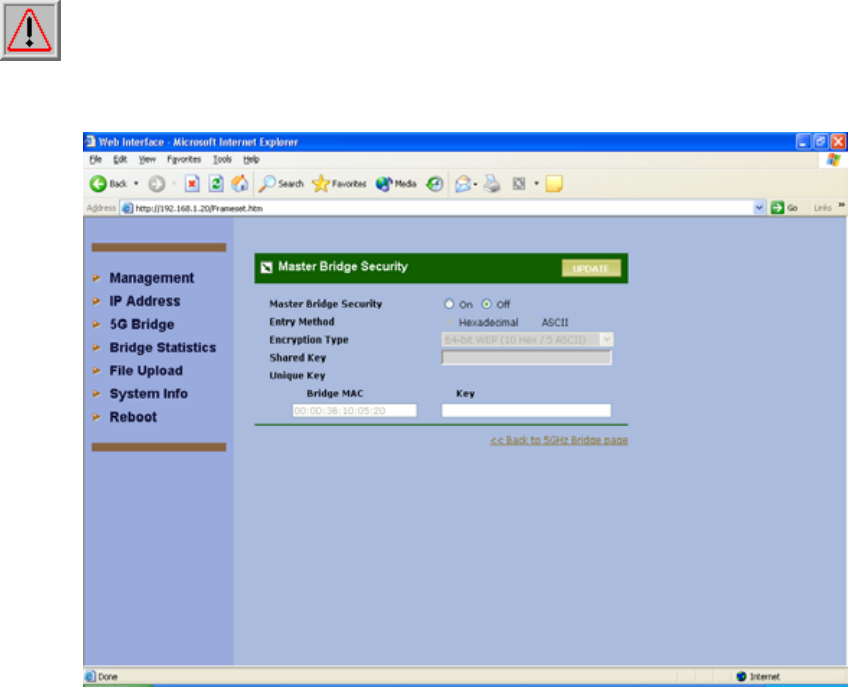
Picture 18 Master Bridge Security Setup
1) Master Bridge Security
Enable/Disable bridge’s security setting.
2) Entry Method
Hexadecimal -- The key input must be hexadecimal (0-9, A-F).
ASCII Text -- The key input can be any character.
3) Encryption Type
The encryption mechanism can be 64/128/152 “WEP”.
Master Side
A. Share Key – Hexadecimal / ASCII Mode
When Share Key is set, all Master-Slave links use this key to encrypt except the
link(s) specified with Unique Key. To setup Share Key, please input “Entry
ALink-5801a Wireless LAN Outdoor Bridge
ALCON Telecommunications Co., Ltd. 30
Method” and “Encryption Type” first.
B. Unique Key
In some special applications, you may need to assign different key for each
Master-Slave link instead of the same key for all links. It can be done by setting
up Unique Key per MAC address of Slave Bridge.
Note: It is required to have the same security setting between linked Bridges to
communicate.
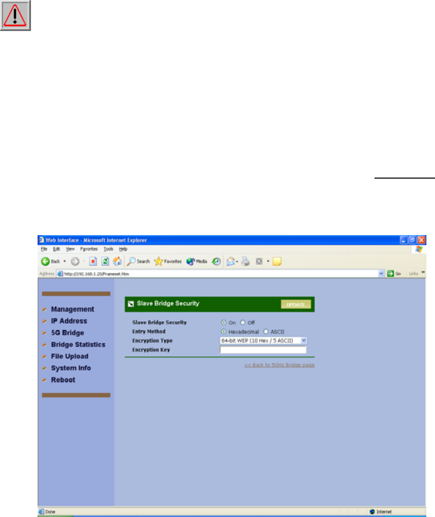
Slave Side
Slave Bridge security setting may apply on bridges of “Point-to-Point” network as well as
“Point-to-Multipoint” network.
For a “Point-to-Point” bridging network, 2 bridges to communicate each other need to use
the same key of same encryption type.
For a “Point-to-Multipoint” bridging network, the key and encryption type need to be the same
with Unique Key setting assigned to this Slave Bridge. Or, if there is no corresponding Unique
Key being assigned on Master Bridge, then Slave Bridge should follow the Share Key
assigned on Master Bridge.
Picture 19 Slave Bridge Security Setup
ALink-5801a Wireless LAN Outdoor Bridge
ALCON Telecommunications Co., Ltd. 31
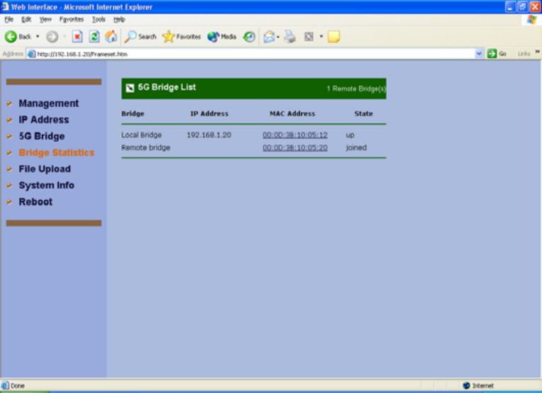
Picture 20 Master/Slave Bridges Connections
4.1.4.2 Master & Slave Bridge joining condition
1) Local Bridge This line shows the IP and MAC address of local Bridge as well
as its state.
2) Remote Bridge This line shows the IP and MAC address of remote Bridge as
well as its state.
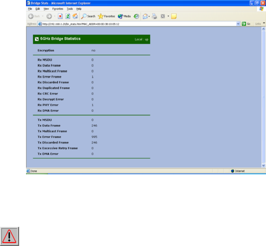
4.1.4.3 Statistics
Clicking MAC address hyperlink of desired remote Bridge, system will show a
Statistics page for you to monitor the information of the bridge link.
ALink-5801a Wireless LAN Outdoor Bridge
ALCON Telecommunications Co., Ltd. 32
Picture 21 Statistics
Values on this page are automatically refreshed every minute. You may manually
press the refresh button of browser to get the updated data more frequent. As RF
signal strength is more critical for outdoor deployment purpose, RSSI bar is refreshed
every 2 seconds.
Note: Due to frequent refresh of Statistics page, it is strongly recommended that you
close this page when performing network performance tests.

ALink-5801a Wireless LAN Outdoor Bridge
ALCON Telecommunications Co., Ltd. 33
Field Description
RSSI Displays the strength of the received signal in dBm (the remote bridge
received signal strenth). Refresh every 2 seconds.
RSSI of ACK Displays the strength of the far end received signals in dBm (the local
bridge received signal strength). Refresh every 2 seconds.
MSDU Maximum service data unit. Displays the number of packets sent and
received by the remote bridge.
Data / Management /
Control Packets can be data, management or control. Displays the number of
packets sent and received for each.
Multicast Displays the number of multicast frames.
Errors Displays the error count for both transmit and receive.
Data Rate Displays the receive and transmit data rate in Mbps.
Receive Errors Displays the number of receive errors.
Discarded Frames Displays the number of receive discarded frames.
Duplicate Frames Displays the number of receive duplicate frames.
CRC Errors Displays the number of receive CRC errors.
Decrypt Errors Displays the number of receive description errors.
PHY Errors Displays the number of receive PHY errors.
DMA Errors Displays the number of receive DMA errors.
Transmit Errors Displays the number of transmit errors.
Discarded Frames Displays the number of transmit discarded frames.
Excessive Retries Displays the number of transmit excessive retries.
DMA Errors Displays the number of transmit DMA errors.
ALink-5801a Wireless LAN Outdoor Bridge
ALCON Telecommunications Co., Ltd. 34
4.2 Firmware and License Upgrade
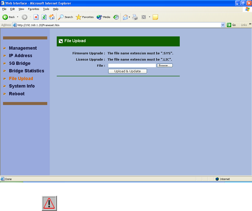
1) Firmware upgrade is for you to upgrade your bridges when the upgrade files release.
2) “ Browse” the firmware files to be uploaded from the Disc in the Picture 20 then click
“ Upload and Update ” when you finish.
3) When uploading successful, users need to reboot the system by clicking “ Reboot ” on
the left side column of the firmware upload page to make it effective.
4) Caution over the traffic on the bridge would be interrupted during system rebooting.
Picture 22 Firmware Upload Web Page
Note: In case network interruption happens during firmware uploading,
system will still keep on current active firmware. You may perform the firmware
upgrade again when network is back to normal.
ALink-5801a Wireless LAN Outdoor Bridge
ALCON Telecommunications Co., Ltd. 35
4.3 Rebooting
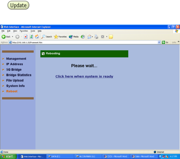
1) Click and “ Reboot “ either “ each time “or “ reboot “ the system once
when you finish all kinds of settings.
Picture 23 Rebooting Window
When all the parameters have been setup according to the network configuration and
requirements, click “Update” and “Reboot“ for parameter changes taking effect. When
starting reboot, system will prompt you a rebooting window. It usually takes at least 30
seconds to finish the reboot process.

ALink-5801a Wireless LAN Outdoor Bridge
ALCON Telecommunications Co., Ltd. 36
5. SNMP
The system provides SNMP v2c read capability for the network management. SNMP
interface can be reached both locally and remotely.
The supported standard MIB including
System of MIB-II
Interfaces of MIB-II
Address Translation of MIB-II
IP of MIB-II
ICMP of MIB-II
SNMP of MIB-II
Besides, the enterprise MIB is also provided especially for Bridge management. The OID
prefix is “1.3.6.4.1.9442.1.3”. OID field in the following table is shortened by specifying only
the digits after prefix.
OID MIB Name Type Description
.1.1.1 dot11StationID string Wireless MAC address of system
.1.1.2 dot11DesiredSSID string The value shall be the same as
SSID of system itself.
.1.1.3 dot11DesiredBSSType int The value shall be 1.
1: Infrastructure; 2: Independent;
3: Any
.1.1.4 dot11BeaconPeriod int The number of TU that shall use
for scheduling Beacon
transmissions.
.1.1.5 dot11DTIMPeriod int The number of beacon intervals
that shall elapse between
transmission of Beacons frames
containing a TIM element whose
DTIM Count field is 0.
.1.1.6 dot11PrivacyOptionImplemented int This value is 1 if WEP is
implemented.
.1.1.7 dot11OperationalRateSet string This string contains 16 ‘0’s.
.1.1.8 dot11AuthenticationAlgorithm int 1: Open system; 2: Share key
.1.1.9 N/A
.1.1.10 N/A
.1.1.11 dot11CountryString string Identify the country the system is
i

ALink-5801a Wireless LAN Outdoor Bridge
ALCON Telecommunications Co., Ltd. 37
operating.
.1.2.1 dot11DisassociateReason int
.1.2.2 dot11DisassociateStation string
.1.2.3 dot11DeauthenticateReason int
.1.2.4 dot11DeauthenticateStation string
.1.2.5 dot11AuthenticateFailStatus int
.1.2.6 dot11AuthenticateFailStation string
.1.3.1 dot11PrivacyInvoked int When this attribute is true, it shall
indicate that the IEEE 802.11
WEP mechanism is used for
transmitting frames of type Data.
.1.3.2 dot11WEPDefaultKeyID int This attribute shall indicate the
use of the first, second, third, or
fourth element of the
WEPDefaultKeys array when set
to values of zero, one, two, or
three.
.1.3.3 dot11WEPKeyMappingLen int The maximum number of tuples
that dot11WEPKeyMappings can
hold.
.1.3.4 dot11ExcludeUnencrypted int
.1.3.5 dot11WEPICVErrorCount counter This counter shall increment when
a frame is received with the WEP
subfield of the Frame Control field
set to one and the value of the
ICV as received in the frame does
not match the ICV value that is
calculated for the contents of the
received frame.
.1.3.6 dot11WEPExcludedCount counter
2.1.1 dot11MACAddress string Wireless MAC address of system
2.1.2 dot11ManufacturerID string Value is “Micorelectronics
Technology Inc.”
2.1.3 dot11ProductID string Value is “BR5811”
2.1.4 dot11ResourceTypeIDName string Value is “RTID”
2.2.1 dot11RTSThreshold int
2.2.2 dot11SwTxRetryLimit int
2.2.3 dot11HwTxRetryLimit int
2.2.4 dot11FragmentationThreshold int

ALink-5801a Wireless LAN Outdoor Bridge
ALCON Telecommunications Co., Ltd. 38
2.2.5 dot11MaxTxMSDULifetime int This value is 512
2.2.6 dot11MaxRxLifetime int This value is 512
2.3.1 dot11TxFragmentCount counter =Tx MSDU on statistics web
2.3.2 dot11MulticastTxFrameCount counter =web’s Multicast-Broadcast on
statistics web
2.3.3 dot11FailedCount counter =TxError on statistics web
2.3.4 dot11RetryCount counter =Excessive Retries on statistics
web
2.3.5 dot11MultipleRetryCount counter
2.3.6 dot11FrameDuplicateCount counter =Duplicated Frame on statistics
web
2.3.7 dot11RTSSuccessCount counter
2.3.8 dot11RTSFailureCount counter
2.3.9 dot11ACKFailureCount counter
2.3.10 dot11RxFragmentCount counter =Rx MSDU on statistics web
2.3.11 dot11MulticastRxFrameCount counter
2.3.12 dot11CRCErrorCount counter
2.3.13 dot11TxFrameCount counter =Tx MSDU on statistics web
2.3.14 dot11WEPUndecryptableCount counter
3.1.1.1 RemoteBridgePhysAddr string The MAC address of remote
bridges.
3.1.1.2 RxRssiDbm string The receiving RSSI in the unit of
dBm. If there is no signal, the
value is “--“.
3.1.1.3 TxRssiDbm string The transmission RSSI in the unit
of dBm. If there is no signal, the
value is “--“.
3.1.2 BridgeDescr string The description of local Bridge.
3.1.3 Distance int The distance set between local
and remote Bridges.
3.1.4 TxPower int full (0); half (1); quarter (2); eighth
(3); min (4)
3.1.5 AutoReboot int enable (1); disable (0)
3.1.6 RssiAuxOutput int enable (1); disable (0)
3.2.1 dot11CurrentChannel int Current channel the system is
using.

ALink-5801a Wireless LAN Outdoor Bridge
ALCON Telecommunications Co., Ltd. 39
3.2.2 dot11CurrentTxRate int Current transmission rate in the
unit of Kbps.

ALink-5801a Wireless LAN Outdoor Bridge
ALCON Telecommunications Co., Ltd. 40
6. Planning Linkage
6.1 Site Survey
You need to consider the following operating and environmental conditions when
performing a site survey:
Data rates – The sensitivity and the radio range are inversely proportional to
data rates. Therefore, the maximum radio range is achieved at the lowest
workable data rate, and a decrease in receiver threshold sensitivity occurs as
the radio data rate increases.
Antenna type and placement - Proper antenna configuration is a critical
factor in maximizing radio range. As a general rule, the radio range
increases in proportion to antenna gain and height.
Physical environment - Clear or open areas provide better radio range than
closed or filled areas. Clear line of sight (LOS) is required to establish a
good and reliable wireless link.
Obstructions - Metal shelving or a steel pillar can hinder devices. To avoid
placing these devices in locations where those obstructions are between the
sending and receiving antennas.

ALink-5801a Wireless LAN Outdoor Bridge
ALCON Telecommunications Co., Ltd. 41
6.2 Data Rate
According to the following table, you will have the idea about over what range the
ALink-5801a with what kind of antenna could operate under what data rate. You
might also know the relationship between the data rate and the maximum radio range;
for example, the bridge with 12dBi antenna could operate well under 6 Mbps data rate
within 17 KM.
Data Rate Maximum Distance
(12dBi Antenna)
Maximum Distance
(23dBi Antenna)
6 Mbps 17.72 KM 30.79KM
9 Mbps 16.82KM 29.36 KM
12 Mbps 16.07KM 28.07 KM
18 Mbps 14.64KM 25.60 KM
24 Mbps 11.66 KM 20.26 KM
36 Mbps 8.21 KM 16.85 KM
48 Mbps 3.72KM 12.23 KM
54 Mbps 1.84 KM 7.32 KM
Table 1 Evaluated Maximum Distance
6.3 Planning Radio Path
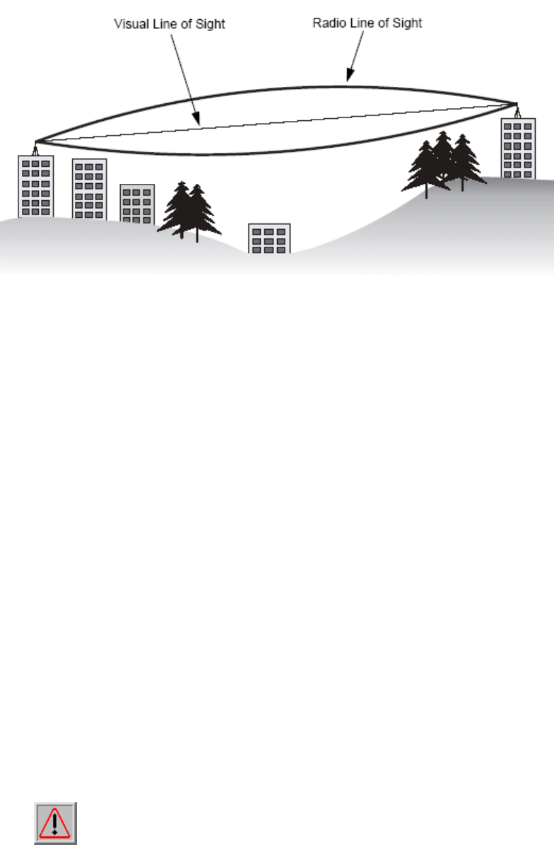
For the wireless communication, the Line-of-Sight (LOS) will be the major issue
over building up the wireless link. This evaluated procedure is to reduce the
obstructions and to avoid the multiple-path signal degrading the communication
quality.
The first requirement is the Line-of-Sight (LOS) between the both sides’
Antennas. The radio line-of-sight concept is the area along the radio linking path
through which is the bulk of the radio signal power travels. The area is known as
the first Fresnel Zone of the radio link. For the radio link, it should avoid to be
affected by obstacles in this path, including the ground within 60% of the first
Fresnel Zone.
The following figure illustrates the concept of a good radio line-of-sight.
ALink-5801a Wireless LAN Outdoor Bridge
ALCON Telecommunications Co., Ltd. 42
Picture 24 Line-of-Sight (LOS)
If there is any obstacle in the radio path, it may still be a radio link but the
quality and the signal strength will be affected. Ensuring the maximum
clearance from objects on a path is important to locate the antennas and the
height. For the long-distance links, the radio signals might be lost partially due to
the non-LOS issue.
As we setup the radio path for the wireless bridge link, it needs to consider
these factors:
• Avoid any partial line-of-sight between the antennas.
• Be aware of trees that may be near the path or obstruct the path.
• Make sure there is enough clearance from buildings and there is no any
building or construction blocking the path.
• Check the land topology between the antennas using topographical maps,
aerial photos, or even satellite image data.
• Avoid a path that may have the temporary blockage due to the moving
objects, such as cars, trains, or aircrafts.
Note: For the wireless link less than 500 m, the IEEE 802.11a radio
signal will tolerate some obstacles in the path and may not even require a
visual line of sight between the antennas.
ALink-5801a Wireless LAN Outdoor Bridge
ALCON Telecommunications Co., Ltd. 43
6.3.1 Antenna Height
The reliable wireless linkage usually depends on the both sides’
antennas for a clear radio line of sight. The minimum height is up to the link
distance, obstacles that may be in the path, topology of the terrain, and the
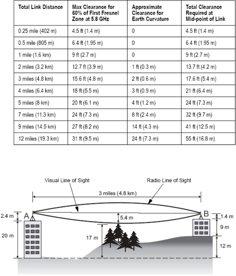
curvature of the earth (for links over 2 miles). For the long-distance links,
the mast or the pole may need to be constructed to attain the minimum
required height. The following table is for you to estimate the required
minimum clearance above the ground or path
obstruction.
Table 2 Estimated LOS Clearance
Picture 25 Antenna Height
ALink-5801a Wireless LAN Outdoor Bridge
ALCON Telecommunications Co., Ltd. 44
For example, the wireless link between the building A and the building B
is located three miles (4.8 km) away. There is a tree-covered hill in the
mid-way. From the table above, it can be seen that for a three-mile link and
the object clearance required at the mid-point is 5.4 m (17.6 ft). The
tree-covered hill height is at an elevation of 17 m (56 ft), so the antennas
linkage on both sides need to be at least 22.4 m (73 ft) high. The building A
is six stories high or 20 m (66 ft), so the mast or pole with 2.4 m (7.9 ft) must
be constructed on its roof to meet the required antenna height. The building
B is only three stories high or 9 m (30 ft) but it is located at an elevation that is
12 m (39 ft) higher than the building A. A mast or pole is required to mount
an antenna at the required height 1.4 m(4.6ft) on the roof of building B.
6.3.2 ANTENNA TYPES
Each antenna must have the FCC-approved for use with the bridge.
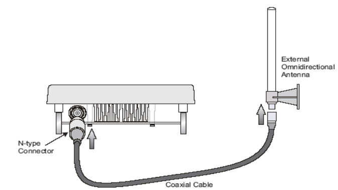
The antennas provide omnidirectional, directional, or diverse coverage and
support various communication distances. Antennas are available with
different gain ratings and coverage areas. The following figure is to show
you one of these combinations, for example; the Bridge comes with the
omnidirectional Antenna.
Picture 26 The Bridge with the omnidirectional antenna
6.3.3 Antenna Cable
An antenna cable introduces signal losses in the antenna system for
both the transmitter and receiver. To reduce signal loss, you should
minimize the cable length and use only low-loss antenna cable to connect
your radio device to the antenna.
ALink-5801a Wireless LAN Outdoor Bridge
ALCON Telecommunications Co., Ltd. 45
6.3.4 Weather Affection
The weather plays one of major matters to the antenna performance for
the wireless communication. The raining day, the lightning day, the cloudy
day, or the windy day will make a quite big impact to the both side antennas
over the communication results. It will also cause the communication quality
unstable.
ALink-5801a Wireless LAN Outdoor Bridge
ALCON Telecommunications Co., Ltd. 46
7 Field Installation
7.1 Unpack the shipment
7.1.1 Required Tools:
Utility knife
Clean and flat working surface
Check the equipments and the installation kits against the packing list to
ensure that the equipment part numbers, parts, and the ancillary equipments
included in the shipment match what is specified on the packing list. The
shipment consists of an ODU and an installation kit in the container. If there
is any difference from the packing list, you will need to contact the sales
representative.
Please, inspect the equipment to see if there is any shipping damage.
If it does have any damage, you could contact the sales representative for
repair or replacement.
7.1.2 Product
ALink-5801a Outdoor Bridge x 1
7.1.3 Accessories
Outdoor Mounting Kits x 1(Set)
DC Injector /RJ45 (RJ45DI-48) x 1
CAT5/25M-RJ45 ( PoE Cable ) x 1
AC/DC Power Supply (DC48V 1.37A) x 1
N-Type to N-Type RG-400/1.5M cable x 1
Installation Guide x 1
Utility and User’s Manual CD x 1
ALink-5801a Wireless LAN Outdoor Bridge
ALCON Telecommunications Co., Ltd. 47
7.2 Installing the ODU
7.2.1 Required Tools:
1) Screw Driver
2) Sealing Type
7.2.2 Installed Accessories:
1) Antenna Mounting Set x 1
2) Grounding rod x 1
3) Waterproof Seal
4) Ethernet Cable x 1
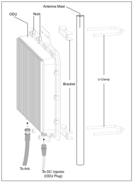
7.2.3 How to Mount the Bridge:
You could follow the steps to mount the bridge as below:
Picture 27 Mount the ODU on the Mask or the Pole
ALink-5801a Wireless LAN Outdoor Bridge
ALCON Telecommunications Co., Ltd. 48
7.2.4 Connecting the cable
An Ethernet cable connects to the power over Ethernet (P.O.E.) output port.
Another Ethernet cable (RJ – 45; the crossover cable) connects to the Power over
Ethernet (P.O.E.) input port. The POE AC Adapter supplies the AC power to the
bridge system.
7.2.5 General Antenna and Safety Tips
When installing an antenna, follow these general tips:
For most elevated antenna installations, we recommend you to ask the
professional installers for proper installation and safety.
For the safety reasons, you are recommended never to touch a high-gain
antenna when it is transmitting or point it at any part of your body.
Please, follow carefully the instructions with your antenna.
Keep antennas away from metal objects/obstructions (heating and
air-conditioning ducts, large ceiling trusses, building superstructures, and
major power cabling runs).
Use a directional antenna when you establish a link between two buildings.
A directional antenna must be properly aligned to the point at the other
antenna.
Locate an omnidirectional antenna in the middle of the desired coverage
area if possible.
Place the antenna as high as possible to increase the coverage area.
Outdoor antennas should be mounted at a sufficient height to prevent the
radio path from above the obstructions such as trees and buildings.
Antenna towers should keep a safe distance from overhead power lines.
The recommended safe distance is twice the tower height.
Use the special ground rods and follow the National Electrical Code for the
outdoor antenna and tower grounding properly.
To prevent water from entering into the antenna cable and be sure to seal
all external cable connectors using commercial products just like coax
compatible electrical tape and Coax-Seal.
ALink-5801a Wireless LAN Outdoor Bridge
ALCON Telecommunications Co., Ltd. 49
7.2.6 Basic Antenna Alignment
When you use directional antennas to communicate between two bridges,
you must manually align the antennas for proper bridge operation. Directional
antennas have greatly reduced radiation angles. The radiation angle is
approximately 25 to 30 degrees, and the parabolic dish antennas radiation angle
is approximately 12.5 degrees.
You can use the link-testing tool to help measure the alignment of two
antennas after the bridges are associated. The link-testing tool provides you
information you can use to gauge the alignment.
7.2.7 ESD Protection
The ESD (electrostatic discharge) can damage the electronic components.
The ESD can cause latent damage that results in premature failure even if
components remain function. The equipments must be properly grounded.
The technical people always need to wear the proper ESD grounding straps and
make sure the ESD grounding strap connecting to the ESD connector during
equipment installation, maintenance and repairs.
7.2.8 Review the Installation
When you finish installing the bridges and aligning the Antennas, you need to
secure all cable connection is tight properly.
Secure the Antenna mounting set is tight after the alignment.
Check the cable connection is between the Antenna and the bridge is tightly.
Make sure the grounding strip is properly connected to the Ground.
Check the cable to POE adapter is connected correctly.
Make sure the cable from the PC or the notebook to the POE adapter is
connected appropriately.
Make sure the POE adapter’s light is on.
Make sure you use the right cables during the installation.
Make sure all connectors are sealed with the waterproof seal.
Configure the ODU with the setting you want before the field installation.
Check if the both side bridges having the same radio settings.
Make sure you set up the both MAC address on each side
After taking all of these checks, you need to use the Web UI to test the
link quality and to see if the RSSI value is in the right value range. You
might need to do the Antenna alignment again if the performance is not good
enough.
ALink-5801a Wireless LAN Outdoor Bridge
ALCON Telecommunications Co., Ltd. 50
Appendix A
GLOSSARY
Auto Reboot Specifies the enable/disable of auto reboot function for auto recovery.
Authentication Type Specifies open-system or shared key.
Authentication / Deauthentication Always 0 for Bridge
Bridge Distance Enter the value (1 – 28 KM) to specify the distance between a pair of bridges.
Cipher Advertised Specifies current state of advertised cipher negotiations, AES and/or
WEP, and None.
CRC Errors Specifies the number of receive CRC errors.
Data Rate Specifies rate of data transmission. Best selection will adapt the rate to the best
available.
Data / Management / Control Packets can either be data, control, or management.
Specifies the number of packets sent and received for each.
Discarded Frames - receive Specifies the number of receive discarded frames.
Discarded Frames - transmit Specifies the number of transmit discarded frames.
DMA Errors – receive Specifies the number of receive DMA errors.
DMA Errors – transmit Specifies the number of transmit DMA errors.
Duplicate Frames Specifies the number of receive duplicate frames.
Encryption Specifies the enabled state of encryption either yes or no.
Errors Specifies the error count for both transmit and receive.
Excessive Retries Specifies the number of transmit excessive retries.
Fragment Length Specifies the fragment length. Enter a value between 256 and 2346.
MSDU Maximum service data unit. Specifies the number of packets sent and
received by Bridge.
Multicast Specifies the number of multicast packets both sent and received.
PHY Errors Specifies the number of receive PHY errors.
Receive Errors Specifies the number of receive errors.
ALink-5801a Wireless LAN Outdoor Bridge
ALCON Telecommunications Co., Ltd. 51
RSSI AUX Output Specifies the activation of RSSI AUX Output for antenna alignment.
RTS/CTS Threshold Specifies the value of the RTS/CTS threshold. Enter a value between
256 and 2346.
State Current state of Bridge.
Transmit Power Specifies the level of transmit power. Choose the value of the transmit power
from the dropdown menu.
Transmit Errors Specifies the number of transmit errors.
ALink-5801a Wireless LAN Outdoor Bridge
ALCON Telecommunications Co., Ltd. 52
Appendix B
TROUBLESHOOTING
The bridges could not associate appropriately with each other:
To make sure the cables is connected properly.
To check the POE adapter’s green light is on or not.
To check the both Frequency settings are on the same channel or not.
To check the data rate is matched with one and another through the statistic RSSI
display or the advance setting inside the Frequency setting.
To make sure you use the same encryption key on the both sides or during the
bridge link.
To check the Antenna is aligned appropriately before the Bridge’s association.
MAC
If you experience the poor performance (high package loss rate) during the
bridge link, it is better for to check the following items:
To check the range is still inside the Antenna range limitation or not.
To make sure the Antenna is aligned properly again.
To make sure if there is no any obstruction in the middle of Line-of-Sign(LOS).
To be sure there is no radio transmitter too close to the bridge s’ Antennas and
relocated the Antennas if you have some around.
To check if you use too close frequency channels to cause the poor link and to set
another channel.
To ping one and another IP address to make sure it will reply or not.
If all recovery measures fail, the bridge still couldn’t function properly and take
this action as what we recommend:
Do not open the bridge box by yourself.
Contact the technical support experts for the troubleshooting.
If you do open the bridge, you will lose the manufacture warranty.