ALFA NETWORK 51AP 802.11b/g AP User Manual AP51 User Guide
ALFA NETWORK Inc. 802.11b/g AP AP51 User Guide
user manual

User Guide
AP51
IEEE
802.11b/g
High-Power
Wireless
AP/Router

Table of Contents
Chapter 1: Introduction 1-1
Package Checklist 1-1
Hardware Description 1-2
LED Indicators 1-3
Ethernet RJ-45 Ports 1-3
Power Socket 1-4
Reset Button 1-4
WPS SET Button 1-4
Chapter 2: Installation 2-1
WISP Mode 2-1
Home Bridge Mode 2-2
Home Router Mode 2-2
Chapter 3: Network Planning 3-1
Internet Gateway Router 3-1
LAN Access Point 3-2
Wireless Client 3-2
Wireless Bridge 3-3
Appendix A: Troubleshooting A-1
Appendix B: Specifications B-1
Glossary

Chapter 1: Introduction
The
AP51
is
an
IEEE
802.11b/g
wireless
High-Power
AP/
Route
that
connects
your
Internet
access
device
(cable
or
ADSL
modem)
to
your
PC
or
local
area
network,
or
to
its
own
secure
wireless
network.
Package
Checklist
The
AP51
AP/Router
package
includes:
1.
AP51
2.
AC
power
adapter
3.
User
Manual
CD
Inform
your
dealer
if
there
are
any
incorrect,
missing
or
damaged
parts.
If
possible,
retain
the
carton,
including
the
original
packing
materials.
Use
them
again
to
repack
the
product
in
case
there
is
a
need
to
return
it.
1-1
1
Introduction
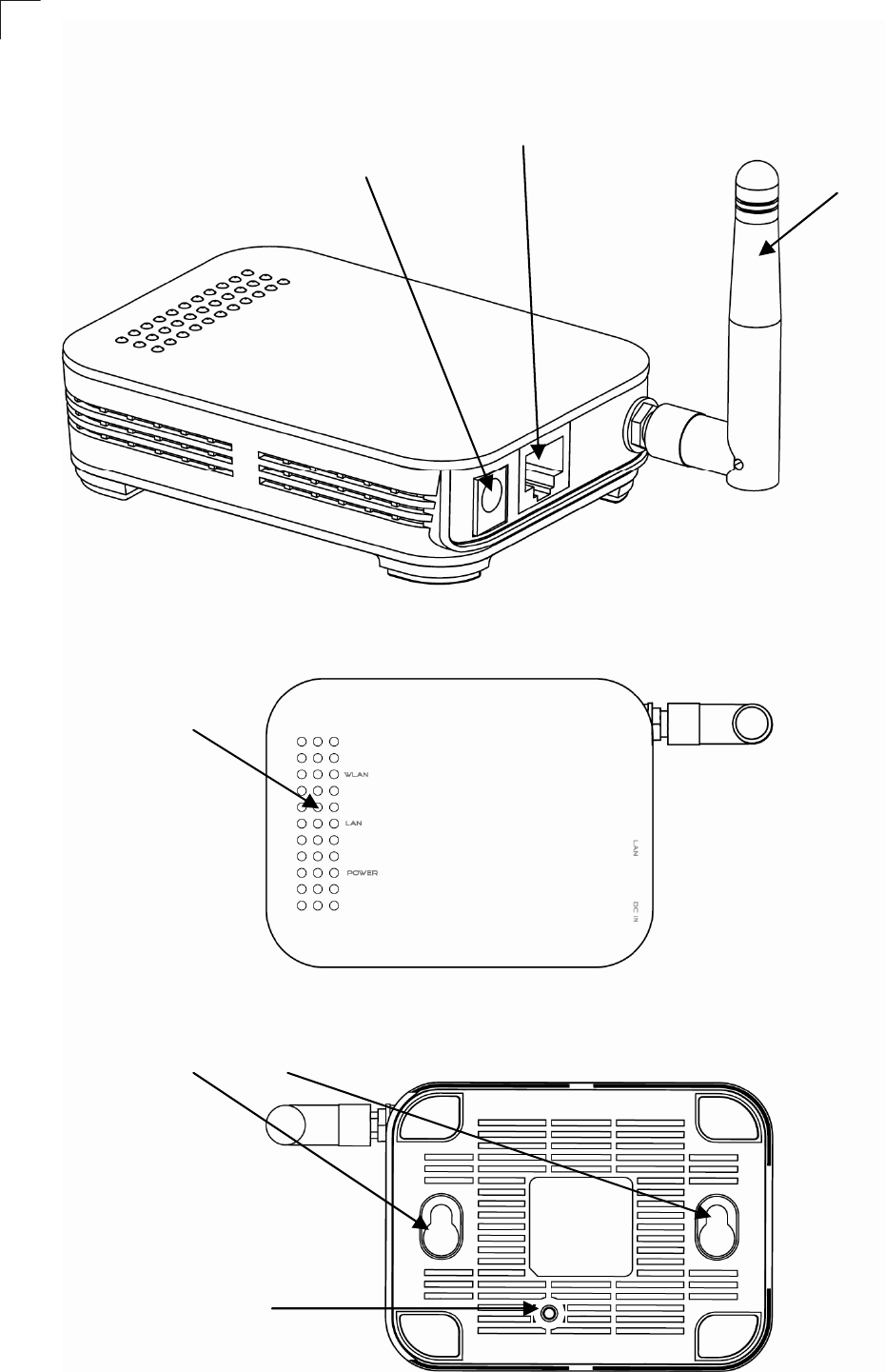
Hardware
Description
1-2
Power Socket
Ethernet RJ-45 Port Detachable
Antenna
LED
Reset Button
Wall Mount Slots
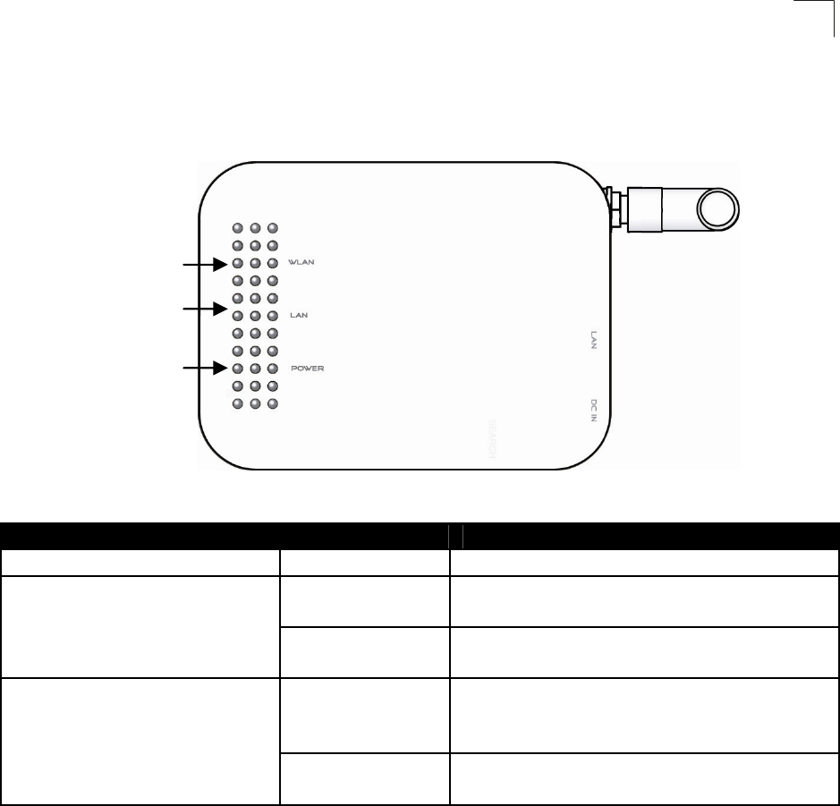
LED
Indicators
Hardware Description
1
The
AP51
includes
three
status
LED
indicators,
as
described
in
the
following
figure
and
table.
LED Status Description
Power On Indicates AP51 is power on
On Indicates a valid link on Ethernet
Port
Ethernet
Off The Ethernet port has no valid
link
On/Flashing Indicates the 802.11b/g radio is
enabled. Flashing indicates
wireless network activity
WLAN
Off Indicates the 802.11b/g radio is
disabled
Ethernet
RJ-45
Ports
The
AP51
has
the
following
RJ-45
ports:
z
As
Ethernet RJ-45
LAN
port
is
for
connection
to
a
PC
or
to
a
10/100
Mbps.
z
As Ethernet RJ-45
WAN
port
is
for
connection
to
a
DSL
or
cable
modem,
or
to
a
LAN
or
other
device
that
provides
your
Internet
access.
The Ethernet RJ-45 port
auto-negotiate
the
operating
speed
to
10/100
Mbps,
the
mode
to
half/full
duplex,
and
the
pin
signals
to
MDI/MDI-X.
Automatic
MDI/MDI-X
support
enables
you
to
use
straight-through
cables
for
all
network
connections
to
PCs,
switches,
or
hubs.
1-3
Wireless Link/Activit
y
Ethernet Link
Power

1
Introduction
Power
Socket
The
AP51
does
not
have
a
power
switch.
It
is
powered
on
when
connected
to
the
AC
power
adapter,
and
the
power
adapter
is
connected
to
a
power
source.
The
power
adapter
automatically
adjusts
to
any
voltage
between
100-240
volts
at
50
or
60
Hz.
No
voltage
range
settings
are
required.
Reset
Button
The
Reset
button
can
be
used
to
restart
the
AP51
or
restore
the
factory
default
configuration.
If
you
press
the
button
for
less
than
5
seconds,
the
AP51
will
restart.
If
you
press
and
hold
down
the
button
for
5
seconds
or
more,
any
configuration
changes
you
may
have
made
are
removed
and
the
AP51
is
restored
to
its
factory
default
configuration.
1-4
Chapter 2: Installation
The
AP51
has
four
basic
operating
modes
that
can
be
set
through
the
web
management
interface:
WISP
Mode
–
work as AP+Client, one interface as AP and the other
interface as Client to access the WISP Station
Home Bridge
Mode
–
work as AP+WDS Reapter, one SSID as AP and
one SSID as Reapter
Home Router
Mode
–
work as AP+Router, Ethernet port become WAN
port to connect to cable or ADSL modem
WISP
Mode
2-1
WISP Base Station WLAN 1 connect to
SSID: WISP
IP:192.168.1.2
SSID: WISP
WLAN 2
IP: 10.0.0.2
SSID: Home
IP:10.0.0.25
IP: 10.0.0.23
2
Installation
ge Mode
Home Bridge
Mode
Home Router
Mode
Internet
Cable or ADSL modem
IP: 10.0.0.2
SSID: Home
IP: 10.0.0.23
IP: 10.0.0.26
Chapter 3: Network Planning
The
AP51
is
designed
to
be
very
flexible
in
its
deployment
options.
It
can
be
used
as
an
Internet
gateway
for
a
small
network,
or
as
an
access
point
to
extend
an
existing
wired
network
to
support
wireless
users.
It
also
supports
use
as
a
wireless
client
to
connect
to
another
wireless
network,
or
a
wireless
bridge
to
connect
two
wired
LANs.
This
chapter
explains
some
of
the
basic
features
of
the
AP51
and
shows
some
network
topology
examples
in
which
the
device
is
implemented.
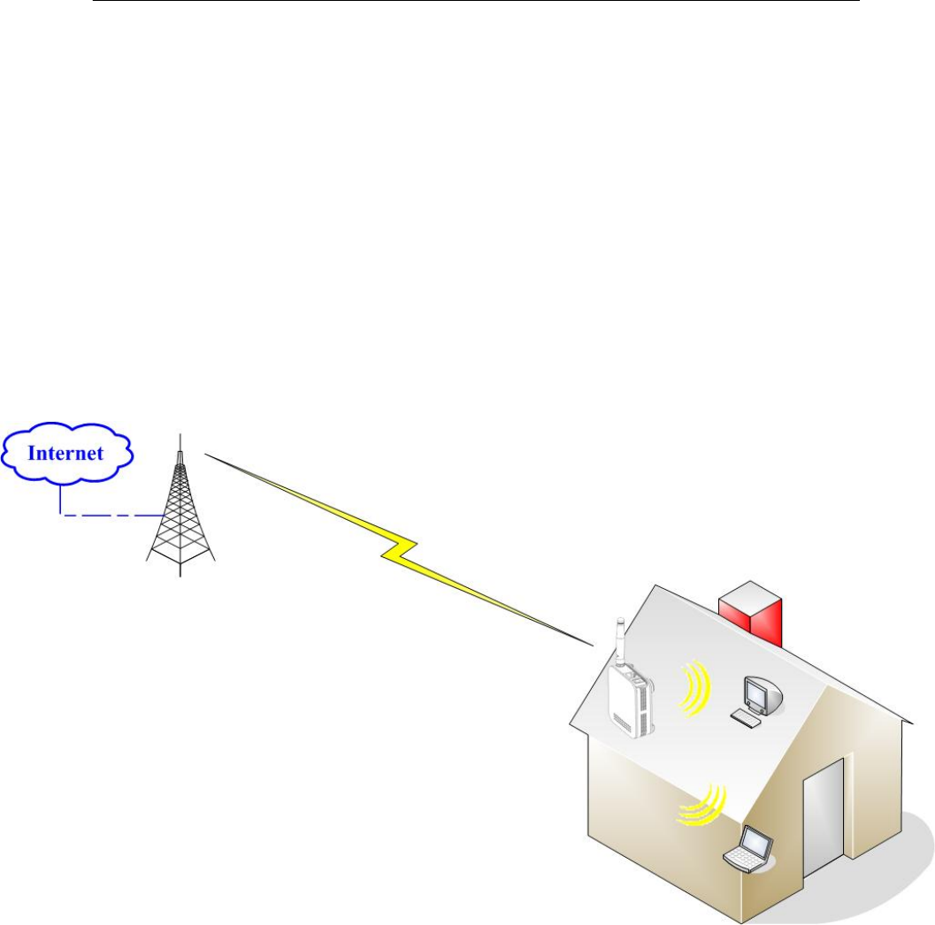
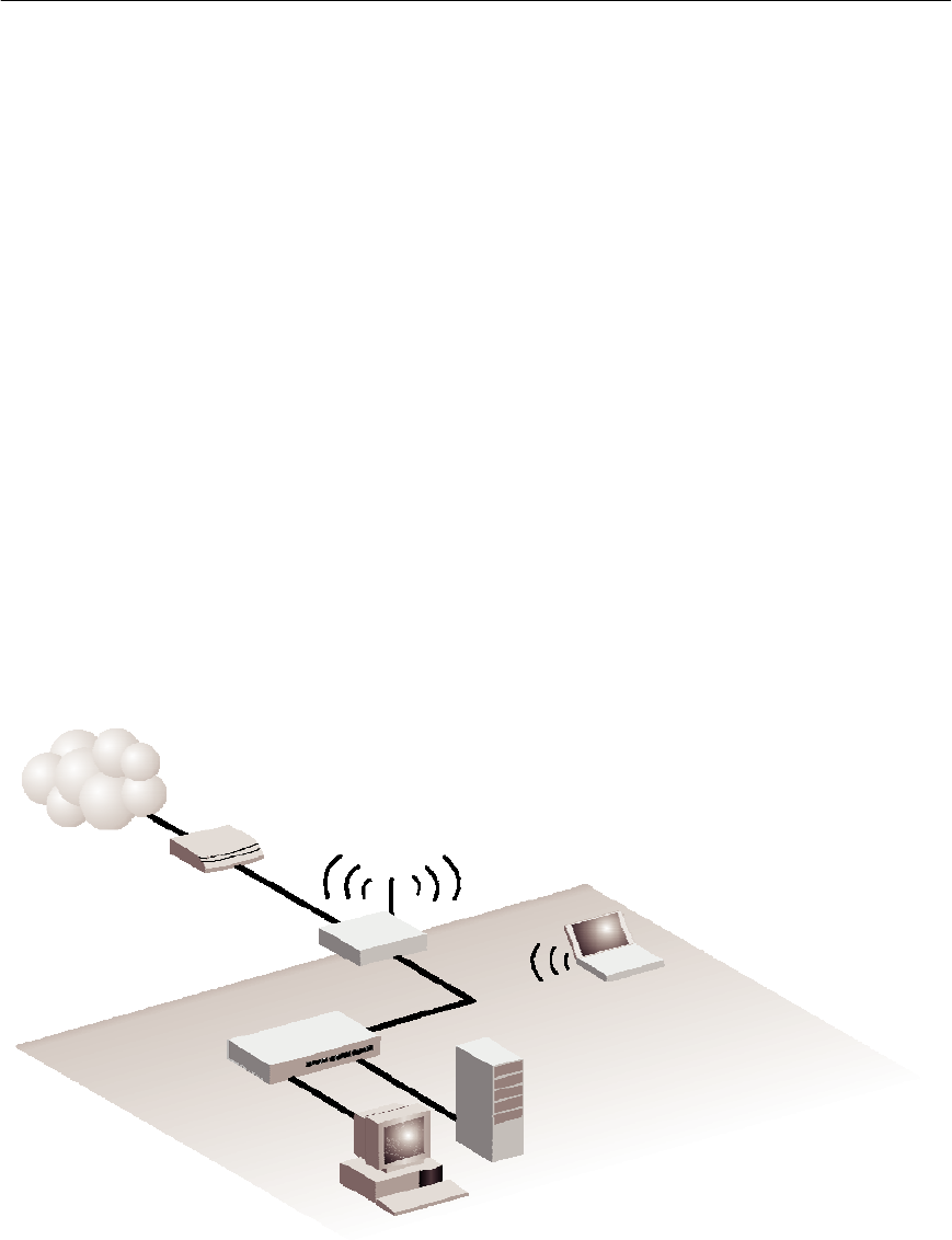
Internet
Gateway
Router
The
AP51
can
connect
directly
to
a
cable
or
DSL
modem
to
provide
an
Internet
connection
for
multiple
users
through
a
single
service
provider
account.
Users
connect
to
the
AP51
either
through
a
wired
connection
to
the
LAN
port,
or
though
the
device
í
s
own
wireless
network.
The
AP51
functions
as
an
Internet
gateway
when
set
to
Router
Mode.
An
Internet
gateway
employs
serveral
functions
that
essentially
creates
two
separate
Internet
Protocol
(IP)
subnetworks;
a
private
internal
network
with
wired
and
wireless
users
and
a
public
external
network
that
connects
to
the
Internet.
Network
traffic
is
forwarded,
or
routed,
between
the
two
subnetworks.
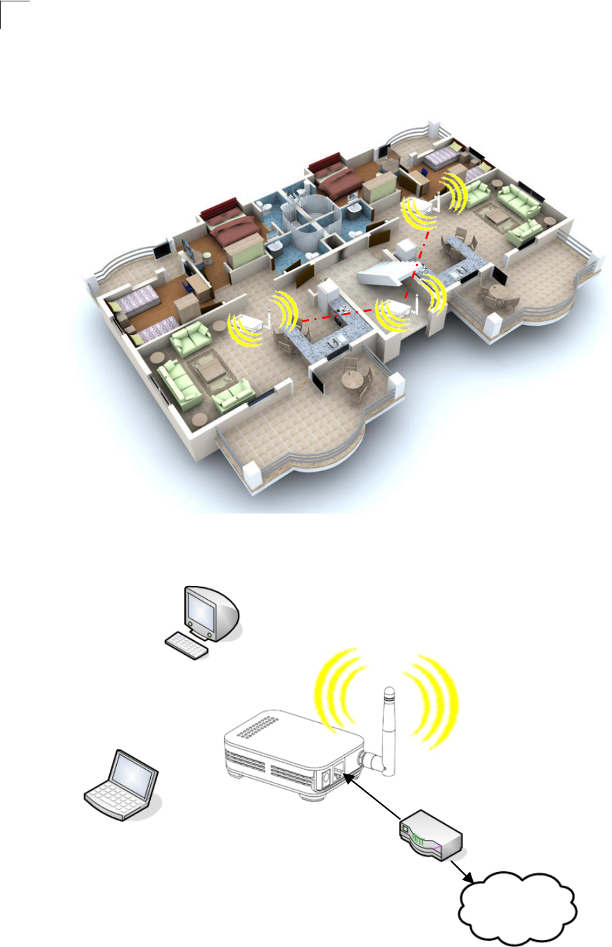
Internet
Service
Provider
Cable/DSL
Modem
AP51 Notebook PC
(IP: 192.168.1.x)
LAN Switch
Server
(IP: 192.168.1.x)
Desktop PC
(IP: 192.168.1.x)
The
private
local
network,
connected
to
the
LAN
port
or
wireless
interface,
provides
a
Dynamic
Host
Configuration
Protocol
(DHCP)
server
for
allocating
IP
addresses
to
local
PCs
and
wireless
clients,
and
Network
Address
Translation
(NAT)
for
mapping
the
multiple
"internal"
IP
addresses
to
one
"external"
IP
address.
3-1
3
Network Planning
The
public
external
network,
connected
to
the
WAN
port,
supports
DHCP
client
and
Point-to-Point
Protocol
over
Ethernet
(PPPoE)
for
connection
to
an
Internet
service
provider
(ISP)
through
a
cable
or
DSL
modem:
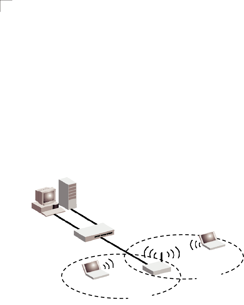
LAN
Access
Point
The
AP51
can
provide
an
access
point
service
for
an
existing
wired
LAN,
creating
a
wireless
extension
to
the
local
network.
The
AP51
functions
as
purely
an
access
point
when
set
to
Bridge
Mode.
When
used
in
this
mode,
there
are
no
gateway
functions
between
the
WAN
port
and
the
LAN
and
wireless
interface.
A
Wi-Fi
wireless
network
is
defined
by
its
Service
Set
Identifier
(SSID)
or
network
name.
Wireless
clients
that
want
to
connect
to
a
network
must
set
their
SSID
to
the
same
SSID
of
the
network
service.
The
AP51
supports
two
separate
wireless
interfaces,
that
is
two
SSIDs
or
Virtual
Access
Points
(VAPs).
The
two
VAP
interfaces
can
be
configured
separately
to
support
different
security
settings
or
other
wireless
functions.
Server
(IP: 192.168.1.x)
Desktop PC
(IP: 192.168.1.x)
LAN Switch Notebook PC
(IP: 192.168.1.x)
Notebook PC
(IP: 192.168.1.x)
AP51
SSID 1
(public)
SSID 2
(private)
Wireless
Client
The
AP51
can
operate
as
a
wireless
client
on
one
VAP
interface,
which
enables
a
connection
to
another
wireless
network.
The
wireless
client
option
requires
the
unit
to
be
set
to
Router
Mode.
When
the
wireless
client
option
is
enabled,
the
client
VAP
interface
functions
as
the
external
gateway
interface
instead
of
the
WAN
port.
The
other
VAP
interface,
LAN
port,
and
WAN
port
all
function
as
the
local
network
within
the
same
IP
subnet.
3-2
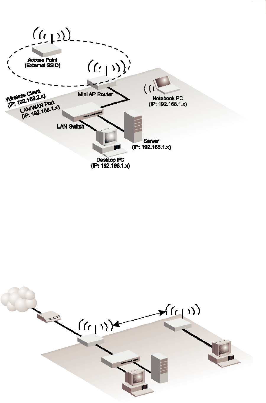
Wireless Bridge
3
Wireless
Bridge
The
IEEE
802.11
standard
defines
a
WIreless
Distribution
System
(WDS)
for
bridge
connections
between
access
points.
The
AP51
can
use
WDS
to
forward
traffic
on
links
between
units.
A
single
WDS
bridge
link
can
be
specified
for
each
VAP
interface.
One
end
of
a
link
must
be
configured
as
the
ì
WDS
Parent
î
and
the
other
as
the
ì
WDS
Child.
î
A
VAP
interface
can
be
configured
as
a
WDS
Parent
when
the
AP51
is
set
to
either
Router
Mode
or
Bridge
Mode,
but
to
be
configured
to
WDS
child
the
unit
must
be
set
to
Bridge
Mode.
Internet
Service
Provider
WDS Child
WDS Parent
Cable/DSL
Modem
AP51
(Router Mode)
AP51
(Bridge Mode)
LAN Switch
Desktop PC
(IP: 192.168.1.x)
Server
(IP: 192.168.1.x)
Desktop PC
(IP: 192.168.1.x)
3-3

Chapter 4: Initial Configuration
The
AP51
offers
a
user-friendly
web-based
management
interface
for
the
configuration
of
all
the
unit’s
features.
Any
PC
directly
attached
to
the
unit
can
access
the
management
interface
using
a
web
browser,
such
as
Internet
Explorer
(version
6.0
or
above).
The
initial
configuration
steps
can
be
made
through
the
web
browser
interface
using
the
Setup
Wizard.
It
is
recommended
to
make
the
initial
changes
by
connecting
a
PC
directly
to
the
AP51
before
installing
it
in
its
intended
location.
The
AP51
has
a
default
IP
address
of
10.0.0.1
and
a
subnet
mask
of
255.0.0.0.
If
your
PC
is
set
to
"Obtain
an
IP
address
automatically"
(that
is,
set
as
a
DHCP
client),
you
can
connect
immediately
to
the
web
interface.
Otherwise,
you
must
set
your
PC
IP
address
to
be
on
the
same
subnet
as
the
AP51
(that
is,
the
PC
and
AP51
addresses
must
both
start
10.0.0.x).
4-1
4
Logging
into
the
Web
Interface
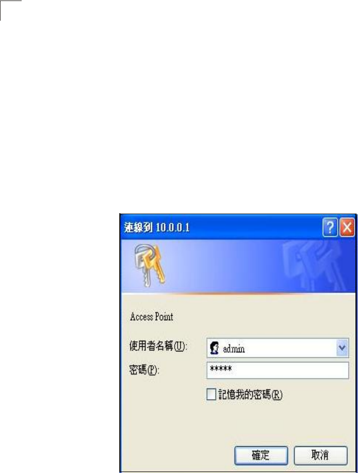
In
the
web
browser
’
s
address
bar,
type
the
default
IP
address:
http://10.0.0.1.
The
web
browser
displays
the
home
page.
The
default
Username
is
“admin”
with
a
default
Password
of
“admin”
Click
OK
to
access
the
web
management
interface.
Note:
It
is
strongly
recommended
that
you
change
the
default
user
name
and
password.
If
the
default
values
are
not
changed,
the
management
interface
is
not
protected
and
anyone
that
can
connect
to
the
access
point
may
be
able
to
compromise
your
network
security.
4-2
** All general function description is on the right of setup each page, will
no descript in this user Guide. **

Appendix A: Troubleshooting
Check
the
following
items
before
you
contact
local
Technical
Support.
1.
If
wireless
clients
cannot
access
the
network,
check
the
following:
I.
Be
sure
the
access
point
and
the
wireless
clients
are
configured
with
the
same
Service
Set
ID
(SSID).
II.
If
authentication
or
encryption
are
enabled,
ensure
that
the
wireless
clients
are
properly
configured
with
the
appropriate
authentication
or
encryption
keys.
2.
If
the AP51
cannot
be
configured
using
a
web
browser:
I.
Be
sure
to
have
configured
the
access
point
with
a
valid
IP
address,
subnet
mask
and
default
gateway.
II.
If
you
are
connecting
to
the
AP51
through
the
wired
Ethernet
interface,
check
the
network
cabling
between
the
management
station
and
the
AP51.
If
you
are
connecting
to
AP51
from
a
wireless
client,
ensure
that
you
have
a
valid
connection
to
the
AP51.
3.
If
you
forgot
or
lost
the
password:
I.
Set
the
AP51
to
its
default
configuration
by
pressing
the
reset
button
on
the
bottom
panel
for
5
seconds
or
more.
Connect
to
the
web
management
interface
using
the
default
IP
address
192.168.1.1.
Then
set
up
a
new
user
name
and
passward
to
access
the
management
interface.
4.
If
all
other
recovery
measure
fail,
and
the
AP51
is
still
not
functioning
properly,
take
any
of
these
steps:
I
Reset
the
AP51
hardware
using
the
web
interface
or
through
a
power
reset.
II
Reset
the
AP51
to
its
default
configuration
by
pressing
the
reset
button
on
the
back
panel
for
5
seconds
or
more.
Connect
to
the
web
management
interface
using
the
default
IP
address
192.168.1.1,
then
setup
a
user
name
and
password.

Appendix B: Specifications
Wireless
Receive
Sensitivity
802.11b:
-90
dBm
@
1
Mbps,
-84
dBm
@
11
Mbps
802.11g:
-86
dBm
@
6
Mbps,
-68
dBm
@
54
Mbps
Operating
Frequency
802.11g:
2.4
~
2.4835
GHz
(US,
Canada)
2.4
~
2.4835
GHz
(ETSI,
Japan)
802.11b:
2.4
~
2.4835
GHz
(US,
Canada)
2.4
~
2.4835
GHz
(ETSI)
2.4
~
2.497
GHz
(Japan)
Data
Rate
802.11g:
6,
9,
12,
18,
24,
36,
48,
54
Mbps
per
channel
802.11b:
1,
2,
5.5,
11
Mbps
per
channel
Operating
Channels
802.11g:
11
channels
in
base
mode
(US,
Canada)
13
channels
(ETSI,
Japan)
802.11b:
11
channels
in
base
mode
(US,
Canada)
13
channels
(ETSI)
14
channels
(Japan)
Modulation
Type
802.11g:
CCK,
BPSK,
QPSK,
OFDM
802.11b:
CCK,
BPSK,
QPSK
AC
Power
Adapter
Input:
100-240
VAC,
50-60
Hz
Output:
12
VDC,
1
A
LED
Indicators
POWER,
LAN
(Ethernet
Link/Activity),
WLAN
(Wireless
Link/
Activity)
B-1

B
Specifications
Network
Management
Web-browser
Temperature
Operating:
0
to
40
°C
(32
to
104
°F)
Storage:
-20
to
70
°C
(32
to
158
°F)
Humidity
15%
to
95%
(non-condensing)
Compliances
FCC
Part
15B
Class
B
EN
55022B
EN
55024
EN61000-3-2
EN61000-3-3
VCCI
Class
B
Radio
Signal
Certification
FCC
Part
15C
15.247,
15.207
(2.4
GHz)
EN
300
328
EN
301
489-1
EN
301
489-17
ARIB
STD-T66
IC
RSS-210
Standards
IEEE
802.1
x
IEEE
802.11b,
g
IEEE
802.3
Wi-Fi
11b/g,
WPA,
WPA2,
WMM
Physical
Size
12.5
x
7
x
2.7
cm
(4.92
x
2.76
x
1.06
in)
Weight
170
g
(6
oz)
B-2

Glossary
10BASE-T
IEEE
802.3
specification
for
10
Mbps
Ethernet
over
two
pairs
of
Category
3
or
better
UTP
cable.
100BASE-TX
IEEE
802.3u
specification
for
100
Mbps
Fast
Ethernet
over
two
pairs
of
Category
5
or
better
UTP
cable.
Access Point
An
internetworking
device
that
seamlessly
connects
wired
and
wireless
networks.
Access
points
attached
to
a
wired
network,
support
the
creation
of
multiple
radio
cells
that
enable
roaming
throughout
a
facility.
Advanced Encryption Standard (AES)
An
encryption
algorithm
that
implements
symmetric
key
cryptography.
AES
provides
very
strong
encryption
using
a
completely
different
ciphering
algorithm
to
TKIP
and
WEP.
Authentication
The
process
to
verify
the
identity
of
a
client
requesting
network
access.
IEEE
802.11
specifies
two
forms
of
authentication:
open
system
and
shared
key.
Backbone
The
core
infrastructure
of
a
network.
The
portion
of
the
network
that
transports
information
from
one
central
location
to
another
central
location
where
it
is
unloaded
onto
a
local
system.
Beacon
A
signal
periodically
transmitted
from
the
access
point
that
is
used
to
identify
the
service
set,
and
to
maintain
contact
with
wireless
clients.
Broadcast Key
Broadcast
keys
are
sent
to
stations
using
dynamic
keying.
Dynamic
broadcast
key
rotation
is
often
used
to
allow
the
access
point
to
generate
a
random
group
key
and
periodically
update
all
key-management
capable
wireless
clients.
Dynamic Host Configuration Protocol (DHCP)
Provides
a
framework
for
passing
configuration
information
to
hosts
on
a
TCP/IP
network.
DHCP
is
based
on
the
Bootstrap
Protocol
(BOOTP),
adding
the
capability
of
automatic
allocation
of
reusable
network
addresses
and
additional
configuration
options.
Glossary-1

Glossary
Encryption
Data
passing
between
the
access
point
and
clients
can
use
encryption
to
protect
from
interception
and
evesdropping.
Ethernet
A
popular
local
area
data
communications
network,
which
accepts
transmission
from
computers
and
terminals.
File Transfer Protocol (FTP)
A
TCP/IP
protocol
used
for
file
transfer.
Hypertext Transfer Protocol (HTTP)
HTTP
is
a
standard
used
to
transmit
and
receive
all
data
over
the
World
Wide
Web.
IEEE 802.11b
A
wireless
standard
that
supports
wireless
communications
in
the
2.4
GHz
band
using
Direct
Sequence
Spread
Spectrum
(DSSS).
The
standard
provides
for
data
rates
of
1,
2,
5.5,
and
11
Mbps.
IEEE 802.11g
A
wireless
standard
that
supports
wireless
communications
in
the
2.4
GHz
band
using
using
Orthogonal
Frequency
Division
Multiplexing
(OFDM).
The
standard
provides
for
data
rates
of
6,
9,
11,
12,
18,
24,
36,
48,
54
Mbps.
IEEE
802.11g
is
also
backward
compatible
with
IEEE
802.11b.
Infrastructure
An
integrated
wireless
and
wired
LAN
is
called
an
infrastructure
configuration.
Local Area Network (LAN)
A
group
of
interconnected
computer
and
support
devices.
MAC Address
The
physical
layer
address
used
to
uniquely
identify
network
nodes.
Network Time Protocol (NTP)
NTP
provides
the
mechanisms
to
synchronize
time
across
the
network.
The
time
servers
operate
in
a
hierarchical-master-slave
configuration
in
order
to
synchronize
local
clocks
within
the
subnet
and
to
national
time
standards
via
wire
or
radio.
Open System
A
security
option
which
broadcasts
a
beacon
signal
including
the
access
point
í
s
configured
SSID.
Wireless
clients
can
read
the
SSID
from
the
beacon,
and
automatically
reset
their
SSID
to
allow
immediate
connection
to
the
nearest
access
point.
Glossary-2

Glossary
Orthogonal Frequency Division Multiplexing (ODFM)
OFDM
allows
multiple
users
to
transmit
in
an
allocated
band
by
dividing
the
bandwidth
into
many
narrow
bandwidth
carriers.
Repeater and Bridge
Repeater
and
bridge
can
provide
an
extended
link
to
a
remote
access
point
from
the
wired
LAN.
Access
Point
working
in
this
mode
could
connect
to
another
AP
in
Access
Point
mode
or
Repeater
and
Bridge
mode.
Whenever
there
are
two
APs
having
wireless
link
together
(one
in
Access
Point
or
Repeater
and
Bridge
mode,
another
using
Repeater
and
Bridge
mode),
and
also
have
wired
link
separately,
these
two
APs
are
also
working
as
ì
bridgin
gî
for
the
two
wired
links.
Service Set Identifier (SSID)
An
identifier
that
is
attached
to
packets
sent
over
the
wireless
LAN
and
functions
as
a
password
for
joining
a
particular
radio
cell;
i.e.,
Basic
Service
Set
(BSS).
Session Key
Session
keys
are
unique
to
each
client,
and
are
used
to
authenticate
a
client
connection,
and
correlate
traffic
passing
between
a
specific
client
and
the
access
point.
Shared Key
A
shared
key
can
be
used
to
authenticate
each
client
attached
to
a
wireless
network.
Shared
Key
authentication
must
be
used
along
with
the
802.11
Wireless
Equivalent
Privacy
algorithm.
Simple Network Time Protocol (SNTP)
SNTP
allows
a
device
to
set
its
internal
clock
based
on
periodic
updates
from
a
Network
Time
Protocol
(NTP)
server.
Updates
can
be
requested
from
a
specific
NTP
server,
or
can
be
received
via
broadcasts
sent
by
NTP
servers.
Temporal Key Integrity Protocol (TKIP)
A
data
encryption
method
designed
as
a
replacement
for
WEP.
TKIP
avoids
the
problems
of
WEP
static
keys
by
dynamically
changing
data
encryption
keys.
Trivial File Transfer Protocol (TFTP)
A
TCP/IP
protocol
commonly
used
for
software
downloads.
Virtual Access Point (VAP)
Virtual
AP
technology
multiplies
the
number
of
Access
Points
present
within
the
RF
footprint
of
a
single
physical
access
device.
With
Virtual
AP
technology,
WLAN
users
within
the
devic
eí
s
footprint
can
associate
with
what
appears
to
be
different
access
points
and
their
associated
network
services.
All
the
services
are
delivered
using
a
Glossary-3

Glossary
single
radio
channel,
enabling
Virtual
AP
technology
to
optimize
the
use
of
limited
WLAN
radio
spectrum.
Wi-Fi Protected Access
WPA
employs
802.1X
as
its
basic
framework
for
user
authentication
and
dynamic
key
management
to
provide
an
enhanced
security
solution
for
802.11
wireless
networks.
Wired Equivalent Privacy (WEP)
WEP
is
based
on
the
use
of
security
keys
and
the
popular
RC4
encryption
algorithm.
Wireless
devices
without
a
valid
WEP
key
will
be
excluded
from
network
traffic.
WPA Pre-shared Key (WPA-PSK)
WPA-PSK
can
be
used
for
small
office
networks
with
a
limited
number
of
users
that
may
not
need
a
high
level
of
security.
WPA-PSK
provides
a
simple
security
implementation
that
uses
just
a
pre-shared
password
for
network
access.
Glossary-4
This equipment has been tested and found to comply with the limits for a Class B digital device, pursuant to Part 15 of the FCC Rules.
These limits are designed to provide reasonable protection against harmful interference in a residential installation. This equipment
generates, uses and can radiate radio frequency energy and, if not installed and used in accordance with the instructions, may cause
harmful interference to radio communications. However, there is no guarantee that interference will not occur in a particular installation.
If this equipment does cause harmful interference to radio or television reception, which can be determined by turning the equipment off
and on, the user is encouraged to try to correct the interference by one of the following measures: -Reorient or relocate the receiving
antenna. -Increase the separation between the equipment and receiver. -Connect the equipment into an outlet on a circuit different from
that to which the receiver is connected. -Consult the dealer or an experienced radio/TV technician for help. This device complies with
Part 15 of the FCC Rules. Operation is subject to the following two conditions: (1) This device may not cause harmful interference, and
(2) this device must accept any interference received, including interference that may cause undesired operation.
You are cautioned that changes or modifications not expressly approved by the party responsible for compliance
could void your authority to operate the equipment.