ALPS ALPINE 9ZUA148 Display and audio unit User Manual iLX 107
Alpine Electronics Inc Display and audio unit iLX 107
Users manual
R
R
Designed by ALPINE Japan
68-30368Z57-B
• OWNER’S MANUAL
Please read before using this equipment.
• MODE D’EMPLOI
Veuillez lire avant d’utiliser cet appareil.
•MANUAL DE OPERACIÓN
Léalo antes de utilizar este equipo.
ALPINE ELECTRONICS OF AMERICA, INC.
19145 Gramercy Place, Torrance,
California 90501, U.S.A.
Phone 1-800-ALPINE-1 (1-800-257-4631)
EN
Thank you for purchasing this Alpine product. Please take a moment to protect your purchase by
registering your product now at the following address: www.alpine-usa.com/registration.
You will be informed of product and software updates (if applicable), special promotions, news
about Alpine.
Merci d’avoir acheté ce produit Alpine. Nous vous invitons à consacrer un moment à la protection
de votre achat en enregistrant votre produit dès maintenant à l’adresse suivante :
www.alpine-usa.com/registration.
Vous serez tenu informé des mises à jour des produits et des logiciels (le cas échéant), des
promotions spéciales et de l’actualité d’Alpine.
Gracias por adquirir este producto Alpine. Con solo unos pocos pasos podrá proteger su producto,
registrándolo a través de la siguiente dirección: www.alpine-usa.com/registration.
Recibirá información sobre nuevos productos y software, promociones especiales y novedades
sobre Alpine.
iLX-107
ALPINE ELECTRONICS MARKETING, INC.
1-7, Yukigaya-Otsukamachi, Ota-ku,
Tokyo 145-0067, JAPAN
Phone: 03-5499-4531
ALPINE ELECTRONICS France S.A.R.L.
184 allée des Erables
CS 52016 - Villepinte
95 945 Roissy CDG cedex
FRANCE
Phone : + 33(0)1 48 63 89 89
ALPINE ELECTRONICS OF AUSTRALIA PTY. LTD.
161-165 Princes Highway,
Hallam Victoria 3803, Australia
Phone 03-8787-1200
ALPINE ELECTRONICS GmbH
Wilhelm-Wagenfeld-Str. 1-3, 80807 München, Germany
Phone 089-32 42 640
ALPINE ELECTRONICS OF U.K. LTD.
Alpine House
Fletchamstead Highway, Coventry CV4 9TW, U.K.
www.alpine.co.uk
ALPINE ITALIA S.p.A.
Viale Cristoforo Colombo, 8
20090 Trezzano sul Naviglio MI, Italy
Phone +39 02 484781
ALPINE ELECTRONICS DE ESPAÑA, S.A.
Portal de Gamarra 36, Pabellón, 32
01013 Vitoria (Alava)-APDO 133, Spain
Phone 945-283588

3-EN
ENGLISH
Contents
Operating
Instructions
WARNING
WARNING ................................................. 5
CAUTION .................................................. 5
NOTICE ..................................................... 5
Features
About Apple CarPlay ....................................... 7
About Home Screen ......................................... 7
Getting Started
Accessory List .................................................. 8
Location of Controls ........................................ 8
Touch Operation ............................................... 8
Turning Power On or Off ................................. 8
Turning the System On ..................................... 9
Adjusting the Volume ....................................... 9
Muting the Sound ............................................. 9
Operating an Item in a List ............................... 9
Using Siri ......................................................... 9
About Hands-Free Phone ............................... 10
Applying Alpine TuneIt App ......................... 10
Adjusting the sound Settings using Alpine
Tunelt App ............................................... 10
Radio/RBDS
Listening to the Radio .................................... 11
Presetting Stations Manually .......................... 11
Presetting Stations Automatically .................. 11
Tuning to Preset Stations ................................ 11
PTY (Program Type) Tuning
(RBDS mode only) ..................................... 11
Displaying Radio Text
(RBDS mode only) ..................................... 11
Apple CarPlay (Optional)
Connecting your iPhone ..................................12
Access to Apple CarPlay ................................12
Auxiliary Device (Optional)
Operating Auxiliary Devices (Optional) .........13
Camera Operation (Optional)
Rear Camera Operation ..................................14
Displaying the rear view video while the car
is in reverse ...............................................14
Display the Rear View Video Manually ......14
Guide Display On/Off Setting .....................14
Adjusting the Caution Display Location .....14
Calling the Adjusted Values of the
Camera .....................................................14
About the Rear Camera Guide ........................14
Other Camera Operation .................................16
About the Adjustment of the Caution Display
Location ...................................................16
About the Adjusted Value of Image
Quality ......................................................16
Setup
Audio Setup
Audio Setup Operation ...................................16
Adjusting Balance (Between Left and
Right) ...........................................................17
Adjusting Fader (Between Front and Rear) ....17
Setting the Bass Level .....................................17
Setting the Treble Level ..................................17
Setting the Subwoofer .....................................17
Turning Subwoofer ON/OFF .......................17
Adjusting the Subwoofer Level ...................17
Setting the Subwoofer Phase .......................17
Setting the Bass Engine SQ ............................17
Turning the Bass Engine SQ ON/OFF ........17
Setting the Bass Engine SQ Type ................17
Adjusting the Bass Engine SQ Level ..........18
Setting the Volume for Each Application .......18
Setting the MX (Media Xpander) ...................18
Equalizer Presets (EQ Presets) .......................18
Setting Defeat .................................................18

4-EN
Display Setup
Display Setup Operation ................................. 19
Switching Display Modes ........................... 19
Adjusting Brightness ................................... 19
Adjusting Color of Picture .......................... 19
Adjusting Image Contrast ........................... 19
Adjusting Picture Quality ............................ 19
Saving and calling the adjusted picture
quality ...................................................... 20
General Setup
General Setup Operation ................................ 20
Time Setting .................................................... 20
Setting the Clock Display ............................ 20
Setting the Time .......................................... 20
Setting the Daylight Saving Time ............... 20
Language Setting ............................................ 20
Setting the Menu Language ........................ 20
Text Scroll Setting .......................................... 21
Setting the Scroll ......................................... 21
Key Sound Setting .......................................... 21
Adjusting the Operating Sound ................... 21
Setting Mute when Reversing ......................... 21
Screen/Lighting Setting .................................. 21
Setting the Brightness of the
Backlighting ............................................. 21
Button Backlighting Adjustment ................. 21
Display Backlighting Adjustment ............... 21
Changing the Opening Image ...................... 21
About iLX-107 ............................................... 21
Displaying the Product Information ............ 21
Initializing the System ................................. 22
Demonstration Setup ...................................... 22
Canceling the Demonstration ...................... 22
Application Setup
Application Setup Operation .......................... 22
Camera Setting ............................................... 22
Setting the Camera Input ............................. 22
Setting the Camera Signal Input ................. 22
Adjusting the Rear Camera Guide .............. 23
Camera Interrupt Setting (Power OFF Mode)
(Rear Camera Only) ................................. 23
Auxiliary (AUX) Setting ................................ 23
Setting the Auxiliary (AUX) Mode ............. 23
Factory System Setup ..................................... 23
Setting the Source Category ........................ 23
Setting the Maestro Module ........................ 23
Apple CarPlay Setting .................................... 24
Setting the WLAN ON/OFF ....................... 24
Registering the Apple CarPlay Device ........ 24
Steering wheel Setting ................................. 24
Setting the Siri Microphone Effect .............. 24
Selecting the Output Speaker ...................... 24
Adjusting the Microphone Level ................. 24
External Accessory Control Setup .................. 24
Setting the External Accessory Control ...... 24
iDataLink Operation
Access to iDataLink Mode ............................. 25
About Parking Sensor screen ...................... 26
External Accessory Control Operation ........... 27
Information
Product Software Update ................................28
In Case of Difficulty ....................................... 28
If this Message Appears ................................. 28
Specifications .................................................. 29
Installation and
Connections
Warning .................................................. 30
Caution ................................................... 30
Precautions ............................................ 30
Installation ...................................................... 31
Uninstalling the original car stereo ............. 31
Mounting the GPS Antenna inside the
vehicle ...................................................... 31
Mounting the Microphone. .......................... 31
Installing the Unit ........................................ 31
Fix the Cables etc. ....................................... 32
Connections .................................................... 34
System Example ............................................. 36
LIMITED WARRANTY
5-EN
Operating Instructions
INSTALL THE PRODUCT CORRECTLY SO THAT THE DRIVER
CANNOT WATCH TV/VIDEO UNLESS THE VEHICLE IS
STOPPED AND THE EMERGENCY BRAKE IS APPLIED.
It is dangerous (and illegal in many states) for the driver to watch
TV/Video while driving a vehicle. Installing this product
incorrectly enables the driver to watch TV/Video while driving.
This may cause a distraction, preventing the driver from looking
ahead, thus causing an accident. The driver or other people could be
severely injured.
DO NOT WATCH VIDEO WHILE DRIVING.
Watching the video may distract the driver from looking ahead of
the vehicle and cause an accident.
DO NOT OPERATE ANY FUNCTION THAT TAKES YOUR
ATTENTION AWAY FROM SAFELY DRIVING YOUR VEHICLE.
Any function that requires your prolonged attention should only be
performed after coming to a complete stop. Always stop the vehicle
in a safe location before performing these functions. Failure to do
so may result in an accident.
KEEP THE VOLUME AT A LEVEL WHERE YOU CAN STILL
HEAR OUTSIDE NOISES WHILE DRIVING.
Excessive volume levels that obscure sounds such as emergency
vehicle sirens or road warning signals (train crossings, etc.) can be
dangerous and may result in an accident. LISTENING AT LOUD
VOLUME LEVELS IN A CAR MAY ALSO CAUSE HEARING
DAMAGE.
MINIMIZE DISPLAY VIEWING WHILE DRIVING.
Viewing the display may distract the driver from looking ahead of
the vehicle and cause an accident.
DO NOT DISASSEMBLE OR ALTER.
Doing so may result in an accident, fire or electric shock.
USE ONLY IN CARS WITH A 12 VOLT NEGATIVE GROUND.
(Check with your dealer if you are not sure.) Failure to do so may
result in fire, etc.
KEEP SMALL OBJECTS SUCH AS SCREWS OUT OF THE
REACH OF CHILDREN.
Swallowing them may result in serious injury. If swallowed,
consult a physician immediately.
USE THE CORRECT AMPERE RATING WHEN REPLACING
FUSES.
Failure to do so may result in fire or electric shock.
DO NOT BLOCK VENTS OR RADIATOR PANELS.
Doing so may cause heat to build up inside and may result in fire.
USE THIS PRODUCT FOR MOBILE 12V APPLICATIONS.
Use for other than its designed application may result in fire,
electric shock or other injury.
DO NOT PLACE HANDS, FINGERS OR FOREIGN OBJECTS IN
INSERTION SLOTS OR GAPS.
Doing so may result in personal injury or damage to the product.
HALT USE IMMEDIATELY IF A PROBLEM APPEARS.
Failure to do so may cause personal injury or damage to the
product. Return it to your authorized Alpine dealer or the nearest
Alpine Service Center for repairing.
NOTICE
Product Cleaning
Use a soft dry cloth for periodic cleaning of the product. For more
severe stains, please dampen the cloth with water only. Anything
else has the chance of dissolving the paint or damaging the plastic.
Temperature
Be sure the temperature inside the vehicle is between +45°C
(+113°F) and 0°C (+32°F) before turning your unit on.
Maintenance
If you have problems, do not attempt to repair the unit yourself.
Return it to your Alpine dealer or the nearest Alpine Service
Station for servicing.
Installation Location
Make sure the iLX-107 will not be installed in a location subjected
to:
• Direct sun and heat
• High humidity and water
• Excessive dust
• Excessive vibrations
WARNING
WARNING
This symbol means important instructions.
Failure to heed them can result in serious injury
or death.
CAUTION
This symbol means important instructions.
Failure to heed them can result in injury or
material property damage.

6-EN
Operation of some of the functions of this unit is very complex.
Because of this, it was deemed necessary to place these functions
into a special screen. This will restrict operation of these functions
to times when the vehicle is parked. This ensures the focus of the
driver’s attention will be on the road and not on the iLX-107. This
has been done for the safety of the driver and passengers.
Some setup operations cannot be made if the car is moving. The car
must be parked and the parking brake must be engaged for the
procedure described in the Owner’s Manual to be valid. The
warning “Unable to operate while driving.” will be displayed if any
attempts are made to perform these operations while driving.
•The iLX-107 draws minimal current even when its power switch is
turned off. If the switched power (ignition) lead of the iLX-107 is
connected directly to the positive (+) post of the vehicle’s battery, the
battery may be discharged.
An SPST (Single-Pole, Single-Throw) switch (sold separately) can be
added to simplify this procedure. Then, you can simply place it in the
OFF position when you leave the vehicle. Turn the SPST switch back
ON before using the iLX-107. For connecting the SPST switch, refer
to the “Connection Diagram of SPST Switch (sold separately)”
(page 33). If the power (ignition) lead is unswitched, it must be
disconnected from the battery post should the vehicle be left unused
for an extended period of time.
Protecting the USB connector
• Only an iPhone 5 or later or Flash memory can be connected to
the USB connector on this unit. Correct performance using other
USB products cannot be guaranteed.
• If the USB connector is used, be sure to use only the supplied
connector cable with the unit. A USB hub is not supported.
• USB Flash memory is used for data file transfer or updates only.
• This unit does not support Flash memory’s Audio/Video
playback or photo browse.
•iPhone, iTunes and CarPlay are trademarks of Apple Inc.,
registered in the U.S. and other countries.
•“Made for iPhone” means that an electronic accessory has been
designed to connect specifically to iPhone, respectively, and has
been certified by the developer to meet Apple performance
standards. Apple is not responsible for the operation of this
device or its compliance with safety and regulatory standards.
Please note that the use of this accessory with iPhone may affect
wireless performance.
CAUTION
Alpine accepts no responsibility for lost data, etc., even if data, etc.,
is lost while using this product.
7-EN
About Apple CarPlay
Apple CarPlay allows your iPhone 5 or later to operate smoothly from this head unit.
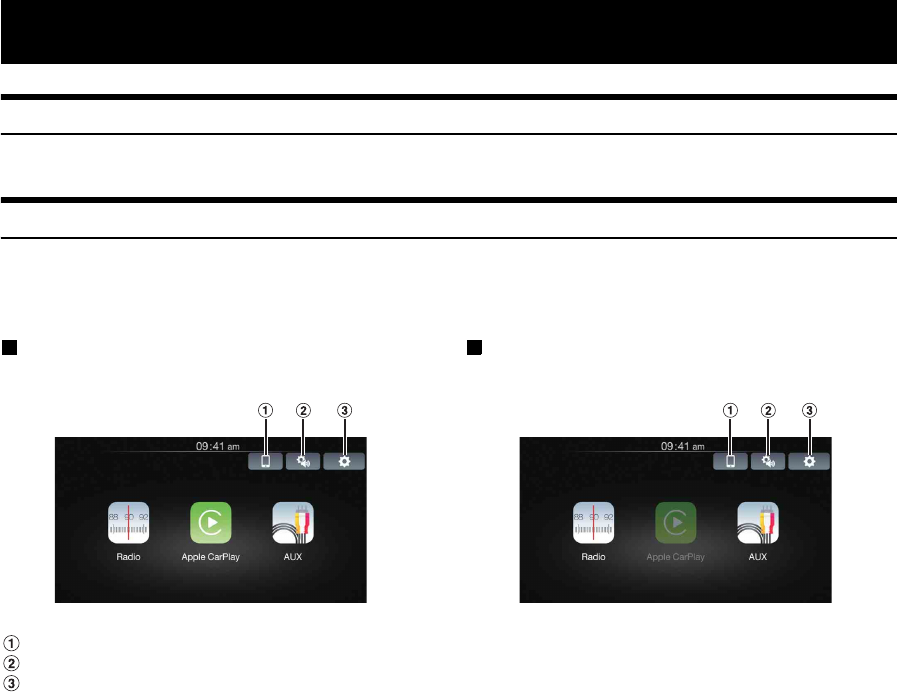
About Home Screen
The Home Screen for this unit gives direct access to those applications designed to work with Apple CarPlay.
The Apple CarPlay icon will indicate whether the appropriate iPhone is connected.
•Available source differs depending on the connected device and settings.
When iPhone is connected When iPhone is not connected
Touch to change to Apple CarPlay Device list screen while “WLAN” is ON.
Audio Setup icon.
Setup icon.
Features
8-EN
Accessory List
•iLX-107.................................................................................1
•Power cable.........................................................................1
•GPS Antenna .......................................................................1
•Antenna mounting plate ......................................................1
•Cable clamp for antenna................................................1set
•USB extension cable ...........................................................1
•PRE OUT cable....................................................................1
•Interface cable ....................................................................1
•W.REMOTE cable ................................................................1
•Flush head screw (M5×8) ...................................................4
•Screw (M5×8) ......................................................................4
•Microphone..........................................................................1
•Face plate ...........................................................................1
•Owner’s Manual ..............................................................1set
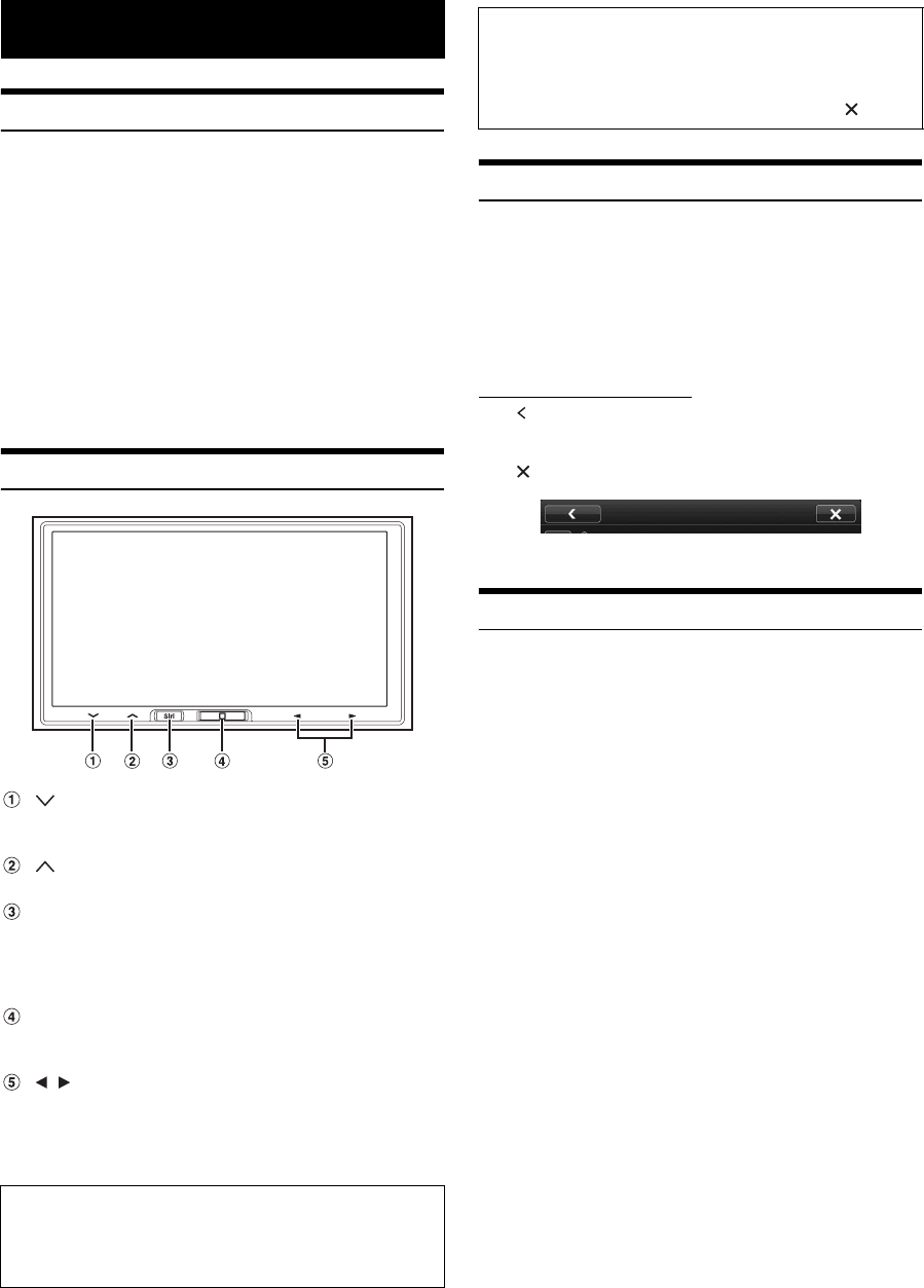
Location of Controls
button
Touch to turn down the volume. Touch and hold for at least 2
seconds to mute.
button
Touch to turn up the volume.
Siri button
Press (or press and hold) to start the Siri function of the
iPhone. When no iPhone is connected, press and hold for at
least 2 seconds to activate Apple CarPlay Device list screen
while “WLAN” is ON.
Home button
Press to call up the Home Screen.
Press and hold for at least 5 seconds to turn the power off.
/ button
This action varies according to the Audio/Visual application.
(Track Up/Down, Fast reverse/Fast forward, etc.)
•You can reset the unit by pressing and holding Home and Siri
buttons at the same time for 10 seconds.
Touch Operation
Many of the operations for this unit are accessible through a light touch
on the integrated touch panel.
•Be sure to touch the onscreen button lightly with the pad of your
finger to protect the display.
•If you touch a button and there is no reaction, remove your finger
from the display once, and try again.
•Onscreen buttons that cannot be operated appear dull in color.
Common onscreen buttons
[]:Returns to the previous screen. Depending on the
function, this button may cancel the operations
performed on the screen.
[]:Closes the window.
Turning Power On or Off
1
Turn the ignition key to the ACC or ON position.
The system turns on.
2
Press and hold the Home button for at least 5
seconds to turn the power OFF.
•The unit can be turned on by pressing Home button or Siri button.
•The iLX-107 is a precision device. Careful handling of the unit
should provide you with years of trouble-free operation.
Getting Started
Steering Wheel remote interface compatible
With an optional Alpine Steering Wheel Remote Control Interface
Box (not included), this unit is controllable from the vehicles
steering wheel controls. For details, contact your Alpine dealer.
About the button descriptions used in this Owner’s
Manual
The buttons found on the face of the unit are expressed in
bold (e.g. Home). The buttons found on the touch-screen
display are shown in bold within brackets, [ ] (e.g. []).
9-EN
Turning the System On
With the Alpine system, when the ignition key is turned to ACC or ON,
the opening screen will be automatically displayed.
1
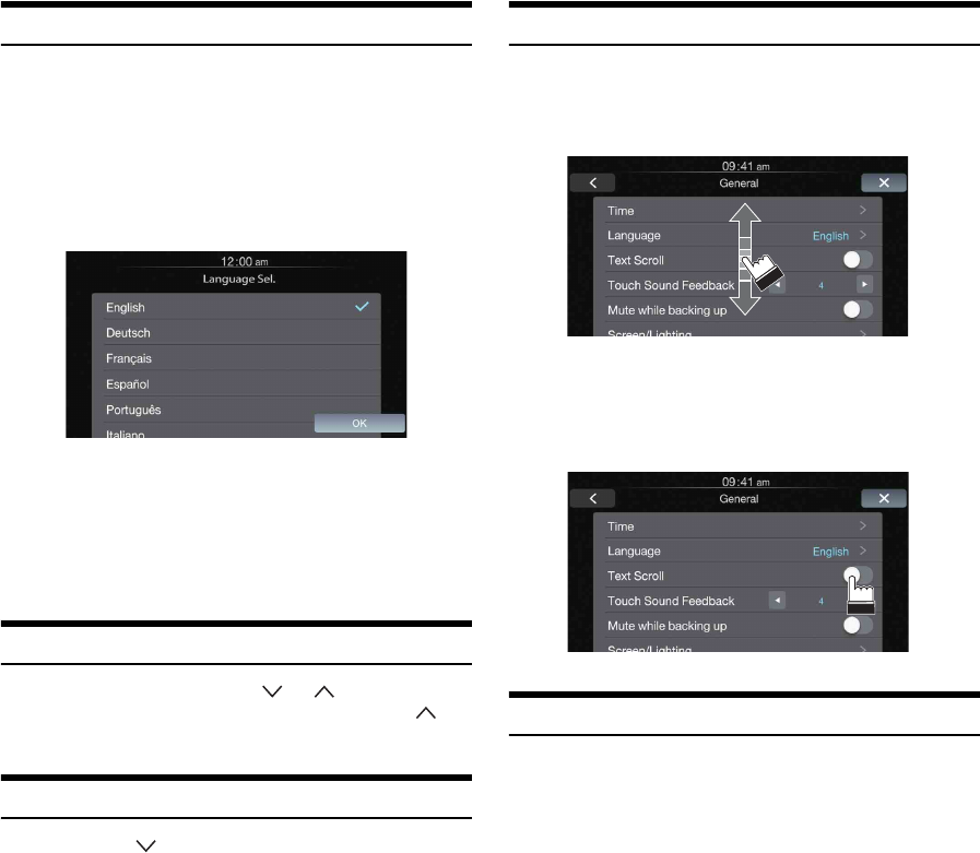
When the system is used for the first time, the
language selection menu is displayed. There are 20
languages to choose from. Touch the screen and
slide your finger up or down, and then touch the
desired language.
2
Touch [OK].
The radio screen is displayed.
•Some of this unit’s functions cannot be performed while the vehicle is
in motion. Be sure to stop your vehicle in a safe location and apply
the parking brake before attempting these operations.
Adjusting the Volume
Adjust the volume by touching or .
Volume increases continuously by touching and holding .
Volume: 0 - 35
Muting the Sound
Touch and hold for at least 2 seconds to activate the
MUTE mode.
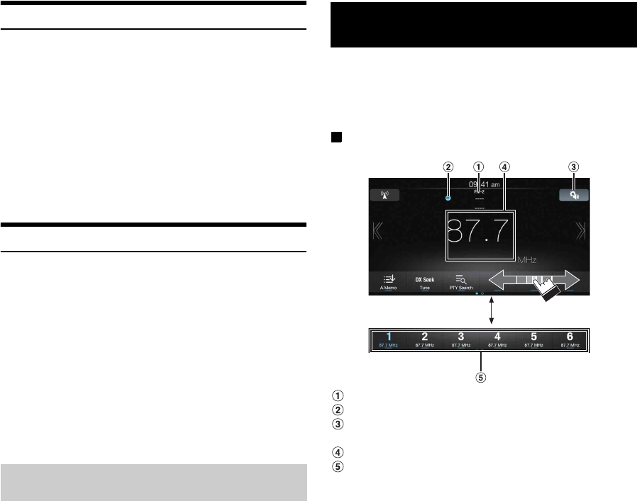
Operating an Item in a List
1
To scroll through a list, touch the screen and slide
your finger up or down.
The screen will scroll along with your finger movement.
•To make a selection, touch the screen at the desired item, and
then lift your finger without moving the screen up or down.
2
Touch the button and slide your finger right or left to
change ON/OFF.
Using Siri
You can use the Siri function of your iPhone. To use Siri from this unit,
make sure that this function is enabled in your iPhone settings.
Press Siri.
10-EN
About Hands-Free Phone
When connected to this unit, your iPhone can be used as hands-free.
Incoming calls are displayed with the caller’s ID when available.
•About iPhone models usable with this unit, refer to Apple CarPlay
section (page 12).
•You can adjust the volume of the phone or select the speakers to be
used for the call’s audio. Refer to “Apple CarPlay Setting”
(page 24).
•Avoid hands-free calls in heavy traffic or on narrow or winding
roads. Keep your focus on driving to prevent an accident.
•Close the windows while calling to reduce background noise.
•When using a microphone, speak as directly as you can into the
microphone to obtain the best sound quality.
Applying Alpine TuneIt App
This unit’s sound tuning is programmable from a connected iPhone. It is
also possible to download specific parameters for certain vehicles from
Alpine’s TuneIt database stored in the Cloud. Using the Alpine TuneIt
App, customized parameters can also be uploaded for others to share
and rate.
The installed Alpine TuneIt App should be launched on the iPhone
before connecting to the head unit.
Alpine TuneIt App, is downloadable from Apple’s App Store. For
details, consult your Alpine dealer.
•The application program and related specifications and data may be
deleted or terminated without notice.
•About iPhone models usable with this unit, refer to Apple CarPlay
section (page 12).
After completing the procedure above, your iPhone can be used to make
audio adjustments for this unit.
1
Make sure the unit is powered on.
2
Launch the Alpine TuneIt App on the iPhone. Adjust
the unit’s sound accordingly on the iPhone.
•Volume level cannot be adjusted via the iPhone.
•The setting cannot be done on both the iPhone and this unit at the
same time.
•When the unit is powered off , sound setting cannot be done via the
iPhone.
•Please obey all local traffic laws while using this function.
The RBDS (Radio Broadcast Data System) is a radio information
system. This system allows you to receive a variety of information such
as traffic information, station names.
•RBDS mode is only available during FM broadcast reception.
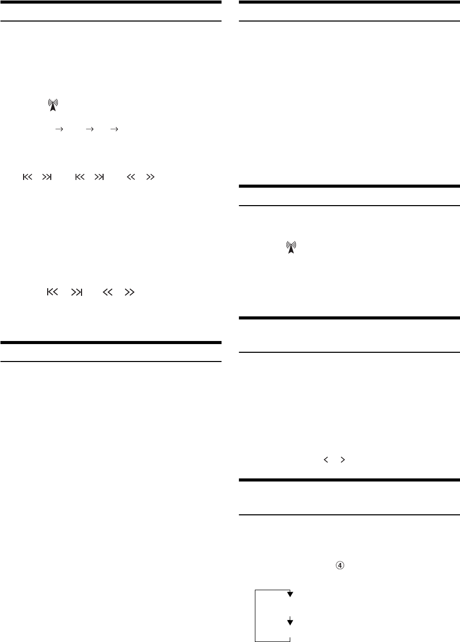
Display example for Radio main screen
Band display
Preset No. indicator display
Audio Setup button (see “Audio Setup Operation” on
page 16)
Info area
Preset button
Adjusting the sound Settings using Alpine
Tunelt App
Radio/RBDS
11-EN
Listening to the Radio
1
Press the Home button.
The Home screen is displayed.
2
Touch [Radio].
The radio mode is activated and the display changes to the
Radio mode screen.
3
Touch [] to select the desired radio band.
Each touch changes the bands as follows:
4
Touch [Tune] to select the tuning mode.
•There are two modes you can select for auto tuning, DX and
Local:
-DX (Distance) mode;
Both strong and weak stations will be tuned in.
-Local mode;
Only strong stations will be tuned in.
The initial setting is DX.
•If “Preset” or “PTY” appears, touch [Tune] repeatedly until a
tuning mode is displayed.
5
Touch [], [] or [], [] to change the radio
frequency up or down respectively.
In manual mode, touch and hold to change the frequency
continuously.
Presetting Stations Manually
1
Tune in a desired radio station you wish to store in
the preset memory by manual or automatic seek
tuning.
2
Touch and hold any one of the preset buttons for at
least 2 seconds.
The selected station is stored.
3
Repeat the procedure to store up to 5 other stations
onto the same band.
To use this procedure for other bands, simply select the
desired band and repeat the procedure.
A total of 18 stations can be stored in the preset memory
(6 stations for each band; FM-1, FM-2 or AM).
•If a preset memory has already been set in the same preset number, it
will be cleared and the new station will be memorized.
Presetting Stations Automatically
The tuner can automatically seek and store 6 strong stations in the
selected band in order of frequency from low to high.
After selecting the desired band, touch and hold
[A.Memo] for at least 2 seconds.
The tuner automatically seeks and stores 6 strong stations into
the preset buttons in order of frequency from low to high.
When automatic storing has completed, the station stored in the
preset 1 is selected.
•If no stations are stored, the tuner will return to the original station
you were listening to before the automatic storing procedure began.
•You can cancel this process by touching [A.Memo] while the tuner is
automatically seeking stations. Cancelling will return the tuner
preset to the previous setting.
Tuning to Preset Stations
Select the desired preset in any band to tune to the station stored in that
preset number.
1
Touch [] repeatedly until the desired band is
displayed.
2
Touch any one of the preset buttons that has a
station stored to it.
The preset station is received.
PTY (Program Type) Tuning (RBDS mode
only)
1
Touch [PTY Search].
The Select PTY list screen is displayed.
2
Touch the selected program type to start searching
for a station of that type.
If no PTY station is found, “No PTY.” will be displayed.
3
To select the station in PTY, touch [Tune] repeatedly
during reception of a PTY station to display “PTY.”
And then, touch [], [].
Displaying Radio Text (RBDS mode
only)
Text messages from a radio station can be displayed.
1
Tune in a radio station that transmits text messages.
2
Touch the Info area ( ) (page 10) in FM radio mode
repeatedly to switch to the desired display.
FM-1 FM-2 AM FM-1
DX Seek Local Seek Manual
Radio Text Mode (Radio Text)
Song Info Mode (PS/PTY/Title Name/Artist Name/Album
Name)

12-EN
Apple CarPlay is a smarter, safer way to use your iPhone in the car.
Apple CarPlay takes the things you want to do with your iPhone while
driving and puts them right on iLX-107. You can get directions, make
calls, send and receive messages, and listen to music, all in a way that
allows you to stay focused on the road. Just plug in or wirelessly
connect your iPhone via WLAN to iLX-107 and go.
•Before using this function, plug in your iPhone using Lighting to
USB Cable (Supplied with iPhone) and make USB connection or
wirelessly connect your iPhone via WLAN to iLX-107. For details,
refer to “Connecting your iPhone” (page 12).
•Some functions may not be available while driving.
About iPhone models usable with this unit
•The following devices have been tested and shown to work with this
unit. Correct function of earlier versions cannot be guaranteed.
iPhone SE: Ver.9.3
iPhone 6s Plus: Ver.9.1
iPhone 6s: Ver.9.1
iPhone 6 Plus: Ver.9.1
iPhone 6: Ver.9.1
iPhone 5s: Ver.9.1
iPhone 5c: Ver.9.1
iPhone 5: Ver.9.1
Connecting your iPhone
You can connect your iPhone to this unit via USB connection or WLAN
by your prefer.
By USB
Just plug in your iPhone using Lighting to USB Cable (Supplied with
iPhone) to iLX-107. If an iPhone has been connected to this unit via
WLAN, you should switch connection on Apple CarPlay Device list
screen.
By WLAN
Make sure to turn on WLAN on your iPhone and iLX-107. Also turn on
Bluetooth on your iPhone before making this connection.
1
Select the “Alpine iLX-107” from the Bluetooth
pairing list of your iPhone for pairing.
Make sure the unit is on Apple CarPlay devices screen for
paring.
2
Touch [pair] or [OK] after the same 6 character
Passkey appears on your iPhone and this unit.
3
If the connection was successful, the Apple CarPlay
screen is displayed.
•In order to use Apple CarPlay over WLAN, the vehicle’s Bluetooth
must be turned off. Please do not pair to the vehicle’s Bluetooth
connection to enable Apple CarPlay.
•You can also connect your iPhone from this unit. For details, refer to
“Registering the Apple CarPlay Device” (page 24).
•When you disconnect a registered iPhone from USB connection on
Apple CarPlay screen, it will change to WLAN connection
automatically.
Access to Apple CarPlay
1
Press the Home button.
The Home screen is displayed.
2
Touch [Apple CarPlay].
The Apple CarPlay mode is activated.
Touch the desired App icon on iLX-107, or use Siri function
by pressing Siri button.
When an iPhone 5 or later is reconnected to this unit during
Radio, setup screen, etc., a message-“Apple CarPlay
Connected” may be displayed on the top of screen for a
short while. Touch the message to change to Apple CarPlay
mode.
•The App must be Apple CarPlay compatible in order to appear in the
Home screen.
Apple CarPlay
(Optional)
13-EN
Operating Auxiliary Devices (Optional)
To operate devices connected to the AUX terminals of iLX-107, follow
the procedure described below.
•Turn on the “AUX In”. Refer to “Setting the Auxiliary (AUX) Mode”
(page 23).
•The video is disabled while driving.
1
Press the Home button.
The Home screen is displayed.
2
Touch [AUX].
The Auxiliary (AUX) mode screen is displayed.
AUX Operation Screen Display During Video File
Playback
Touch the screen.
The Auxiliary (AUX) operation screen is displayed.
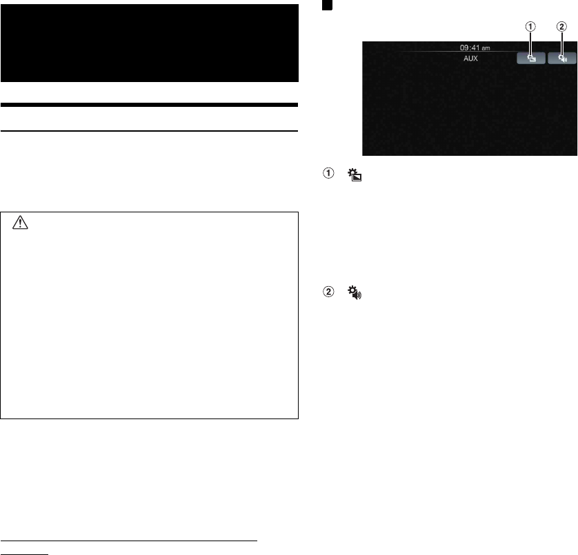
Example for AUX main screen
[]
Calls up the Display Setup screen. (See “Display Setup
Operation” on page 19)
•The operation screen changes to the visual screen in the
Auxiliary (AUX) mode for 5 seconds after an operation has
been performed.
Touch the display panel to display the operation screen
again.
[]
Calls up the Audio Setup screen. (See “Audio Setup
Operation” on page 16)
Auxiliary Device
(Optional)
WARNING
It is dangerous (and illegal in many states) for the
driver to watch TV/video while driving the vehicle. The
driver may be distracted from looking ahead and an
accident could occur.
Install the iLX-107 correctly so that the driver cannot
watch TV/video unless the vehicle is stopped and the
emergency brake is applied.
If the iLX-107 is not installed correctly, the driver will
be able to watch TV/video while driving the vehicle
and may be distracted from looking ahead and cause
an accident. The driver or other people could be
severely injured.
14-EN
The video from an optional camera can be viewed from this head unit’s
display.
Depending on your camera, please choose the camera type first. For
details, refer to “Setting the Camera Input” (page 22).
Front camera:
When a HCE-C212F is connected, conditions in front of the
vehicle, such as objects, people and other hazards, can be
seen.
Rear camera:
If a HCE-C252RD/HCE-C155/HCE-C125, etc., camera is
connected, when the vehicle is reversed, the rear camera view
(guide marks for vehicle width and available distance) is
displayed automatically on the screen of this unit.
Side camera:
If a side camera is connected, you can check for obstacles in
the blind spot on the passenger side.
Rear Camera Operation
Set “Camera” to “Rear”. Refer to “Setting the Camera Input” (page 22).
1
Shift the gear lever to the reverse (R) position.
The rear view image is displayed while the car remains in
reverse.
2
If you shift the gear lever to a position other than
reverse (R), the monitor returns to the previous
screen.
•Never depend solely on the camera when backing up. Always turn
and look and only use the camera for additional assistance.
•The Reverse wire must be properly connected for this function to be
effective.
1
Press the Home button.
The Home screen is displayed.
2
Touch [Camera].
1
Touch the screen when the image from the camera is
displayed.
The operation screen is displayed on the screen.
•After a 5-second time-out, the operation screen returns to the
camera display screen.
2
Touch [Guide Off] on the Rear camera display
screen.
The guide disappears, and then the [Guide Off] switch
changes to [Guide On].
3
Touch [Guide On] to turn on the guide.
1
Touch the screen when the image from the camera is
displayed.
The operation screen is displayed on the screen.
•After a 5-second time-out, the operation screen returns to the
camera display screen.
2
Touch [Caution ↑] or [Caution ↓].
•For each touch, the caution location moves to the top or bottom of the
screen.
You can call the preset values of the camera in “Display Setup”
(page 20).
1
Touch the screen when the image from the camera is
displayed.
The operation screen is displayed on the screen.
After a 5-second time-out, the operation screen returns to
the camera display screen.
2
Touch [Preset].
About the Rear Camera Guide
To display the guide, set “Guide Display On/Off Setting” (page 14) to
On. Also, to adjust the guide, refer to “Adjusting the Rear Camera
Guide” (page 23). You can also turn off the guide in the Rear camera
display screen.
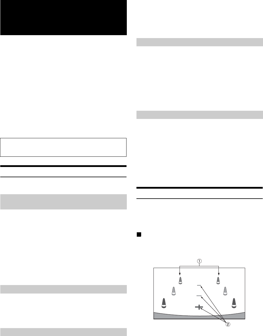
Indication mark meaning
When the car is put into reverse gear, the monitor switches to the rear
view camera image. Guides appear to help visualize the car’s width and
distance from the rear bumper.
1Car width extension marks (red, yellow and green in
order of distance)
If properly calibrated, the marks indicate the car’s width.
This helps guide the car’s path when backing up in a
straight line.
The marks represent the distance from the rear of the car (at
the end of the bumper).
Camera Operation
(Optional)
You can adjust the quality of the camera image.
Setting items: Brightness / Color / Contrast
Refer to “Display Setup Operation” (page 19).
Displaying the rear view video while the
car is in reverse
Display the Rear View Video Manually
Guide Display On/Off Setting
Adjusting the Caution Display Location
Calling the Adjusted Values of the Camera
15-EN
•The marks do not move in synchronization with the
steering wheel.
•Set the marks to suit the car’s width.
2Distance guidance marks
The marks represent the distance from the rear of the car
(from the end of the bumper).
•The marks do not move in synchronization with the
steering wheel.
•We recommend that you measure the actual distance to
the marks when parked on a level surface.
•Depending on the condition of the car or road surface, the range of
vision may vary.
•The camera has a limited range of vision. Objects at extreme angles
to the camera (e.g. under the bumper or at opposite ends of the
bumper) may not be in the its field-of-vision.
•The rear camera image may have a tint which is different from the
actual surroundings.
•Depending on the car, the guidance may deviate to the right or left.
This is not a malfunction.
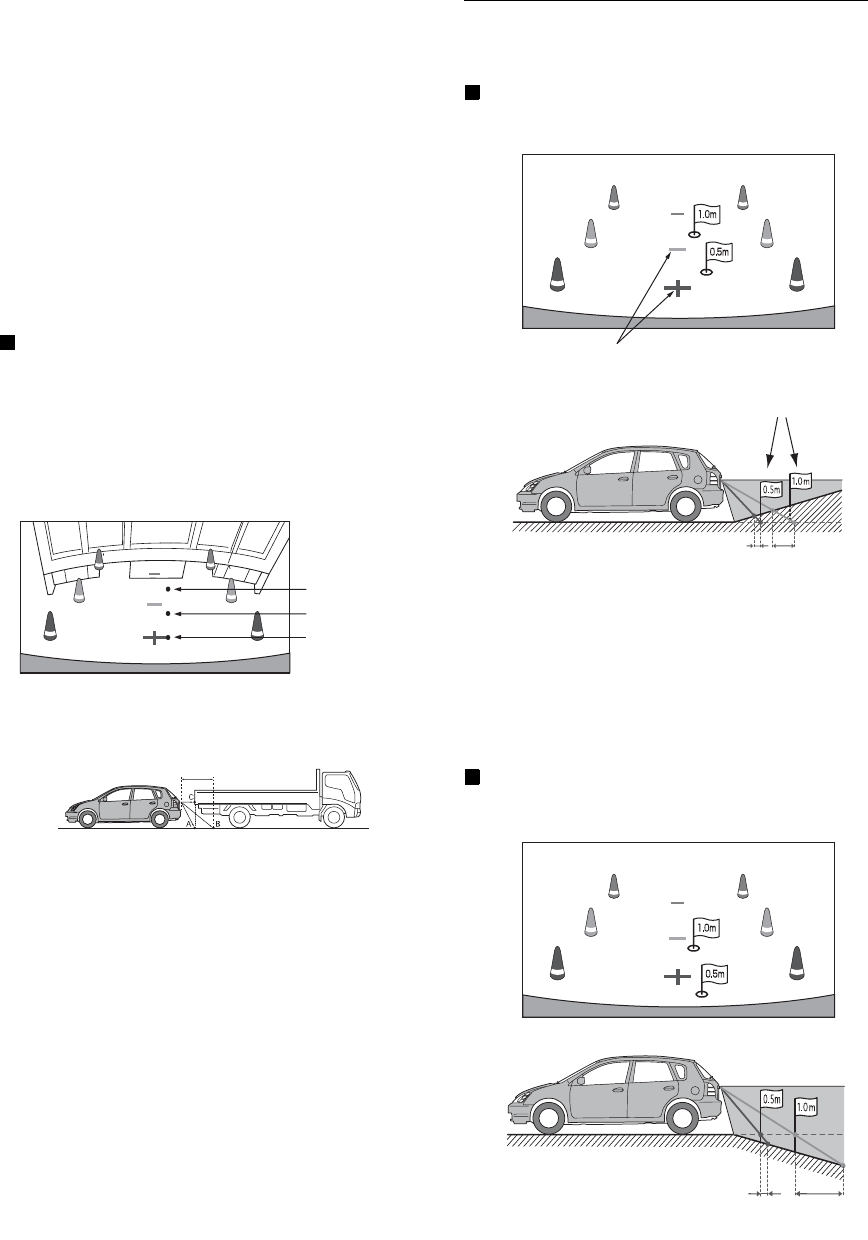
Distance guidance mark
The distance guides represent the ground level distance from the rear
bumper. It is difficult to accurately estimate the distance to objects
above ground level.
In the following example, the distance to A is 0.5 m and the distance to
B is 1 m.
<Screen>
<Positions of A, B and C>
In the screen, according to the distance guidance marks,
the truck seems to be parked about 1 m away (at the
position B). In actual fact, however, if you reversed to
position A, you would collide with the truck.
In the screen, positions A, B and C seem to be located in
order of proximity. However, in actual fact, the position A
and C are the same distance, and B is farther away than
positions A and C.
•The car width extension mark represents the distance to the road
surface. The distance to an object on the road is not accurately
represented by the guides.
•In the following conditions, screen visibility may be impaired. This is
not a malfunction.
-When it is dark (during the night, etc.).
-Under very high or very low temperature conditions.
-When water drops adhere to the camera, or when the humidity
is high (such as rainy weather, etc.).
-When foreign bodies (such as mud, etc.) adhere to the camera
or its peripheral area.
-When sunlight or headlights directly strike the camera lens.
Error between the screen and the actual road surface
In the following conditions, errors are produced between the screen
guidance and the actual road surface. (The illustrations represent a case
when the camera is installed in the standard position.)
When there is a steep upward slope behind the car
(example)
<Screen>
<Situation of the car>
The distance guidance mark represents the distance to a
flat road surface. Therefore in the case of an upward
slope behind the car, the distance guides are displayed
closer to the rear bumper than the actual distance. For
example, if there is an obstacle on the upward slope, it
may appear farther away than its actual position.
Also, an error may occur between the guidance and the
actual path of the car on the road surface.
When there is a steep downward slope behind the
car (example)
<Screen>
<Situation of the car>
C
B
A (about 0.5 m)
about 1 m
Distance guidance marks
Actual distances
Error Error
Error Error
16-EN
In the case of a downward slope behind the car, the
distance guides are displayed farther from the rear
bumper than the actual distance.
If there is an obstacle on the downward slope, it seems
closer than its actual position.
Also, an error may occur between the guidance and the
actual path of the car on the road surface.
Other Camera Operation
Set “Front” or “Side” for “Camera” (page 22).
1
Press the Home button.
The Home screen is displayed.
2
Touch [Camera].
The Caution display location for other cameras can be adjusted. Refer to
“Adjusting the Caution Display Location” (page 14) for the operations.
You can call the preset values of the camera in “Display Setup”
(page 19).
Refer to “Calling the Adjusted Values of the Camera” (page 14) for the
operations.
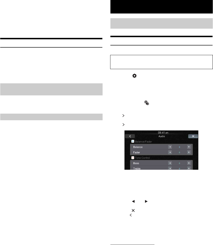
Audio Setup Operation
1
Touch [] on the Home screen.
The Setup main screen is displayed.
2
Touch [Audio].
The Audio Setup screen appears.
•You can display the Audio Setup screen from each application
screen. Touch [] on any application screen.
3
Select the desired item.
If “ ” appears, there is another hierarchy. Touch the desired
item.
If “ ” does not appear, proceed to step 4.
Setting items: Balance / Fader / Bass / Treble / Subwoofer /
Subwoofer Level / Subwoofer Phase / Bass Engine
SQ / Bass type / Bass level / Application Volume /
Media Xpander / EQ Presets / Defeat
•Depending on the setting, displayed items may differ.
4
Touch [] or [] etc., to change its setting.
5
Touch [] to return to the main application screen.
Touch [] to return to the previous screen.
•Immediately after changing the Audio Setup (while the system is
writing data automatically) do not turn the ignition key to OFF.
Otherwise, the settings may not be changed.
•For details on how to operate the list screen, refer to page 9.
About Alpine TuneIt App
You can also set the Audio Setup of this unit through the Alpine TuneIt
App installed to your iPhone.
It is also possible to download specific parameters for certain vehicles
from Alpine’s TuneIt database.
Using the Alpine TuneIt App, customized parameters can also be
uploaded for others to share and rate.
In Sound control mode, “TuneIt connected.” is displayed on the Audio
Setup screen, and you cannot perform any operation.
About the Adjustment of the Caution
Display Location
About the Adjusted Value of Image Quality
Setup
Audio Setup
The following steps 1 to 5 are common operations to each
“Setting item” of Audio Setup. Refer to each section for details.

17-EN
•Alpine TuneIt App is downloadable from Apple’s App Store.
•Time Correction, Crossover and Parametric EQ can be set only
through the Alpine TuneIt App.
•Also refer to “Applying Alpine TuneIt App” on page 10.
Adjusting Balance (Between Left and
Right)
Adjust the right and left speaker volumes.
Setting item: Balance
Setting contents: L (left) 15 to R (right) 15 (Initial setting: 0)
Adjusting Fader (Between Front and
Rear)
Adjust the front and rear speaker volume.
Setting item: Fader
Setting contents: F (front) 15 to R (rear) 15 (Initial setting: 0)
Setting the Bass Level
You can emphasize or weaken the bass level.
Setting item: Bass
Setting contents: -7 to +7 (Initial setting: 0)
•The function is disabled when Defeat is set to “ON”.
•The function is disabled when Bass Engine SQ is set to “ON”.
Setting the Treble Level
You can emphasize or weaken the treble level.
Setting item: Treble
Setting contents: -7 to +7 (Initial setting: 0)
•The function is disabled when Defeat is set to “ON”.
•The function is disabled when Bass Engine SQ is set to “ON”.
Setting the Subwoofer
If an optional subwoofer is connected to the unit, make the following
setting.
Setting item: Subwoofer
Setting contents: ON / OFF (Initial setting)
•The function is disabled when Bass Engine SQ is set to “ON”, and
the Bass Engine SQ parameter downloaded from Alpine TuneIt App
is applied.
You can set the Subwoofer level when a Subwoofer is connected.
Setting item: Subwoofer Level
Setting contents: 0 to 15 (Initial setting: 0)
•If the Subwoofer setting is “OFF”, the setting cannot be set.
•The function is disabled when Bass Engine SQ is set to “ON”.
The subwoofer output phase is toggled Subwoofer Normal (0°) or
Subwoofer Reverse (180°).
Setting item: Subwoofer Phase
Setting contents: 0° (Initial setting) / 180°
•If the Subwoofer setting is “OFF”, the setting cannot be set.
Setting the Bass Engine SQ
Bass Engine SQ is used to easily add impact of varying levels to your
music. Using the different levels available, the Bass impact can be
adjusted for different types of music.
•Using the Alpine TuneIt App, you can download the optimal Bass
Engine SQ tuning data for your speaker system.
Set to “ON” to use the Bass Engine SQ function.
Setting item: Bass Engine SQ
Setting contents: OFF (Initial setting) / ON
•The function is disabled when Defeat is set to “ON”.
You can set your favorite Bass Engine SQ type.
Setting item: Bass type
Setting contents: Standard (Initial setting) / Punch / Low Bass /
Mid Bass / Rich
•The function is disabled when Defeat is set to “ON”.
•The function is disabled when Bass Engine SQ is set to “OFF”.
Turning Subwoofer ON/OFF
Adjusting the Subwoofer Level
Setting the Subwoofer Phase
Turning the Bass Engine SQ ON/OFF
Setting the Bass Engine SQ Type
Standard: A mild low-end boost to overcome road noise.
Punch: A heavier boost with more low-end impact (punch).
Low Bass:Enhance the very low bass to give a much heavier
presence without the punchy mid-bass.
Mid Bass: Focused more on mid-bass for systems with smaller
subwoofers.
Rich: Add boost to all low-end bands for a more bass-filled
sound.

18-EN
With BASS ENGINE SQ ON, adjusting the Bass level uniformly effects
various sound parameters for optimum Bass effect.
Setting item: Bass level
Setting contents: 0 to 6 (Initial setting: 3)
•Adjustable only when Defeat is Off.
•The Bass parameters affected contain Bass Level, Treble Level, EQ
PRESETS, Parametric EQ*, SUBWOOFER*, Subwoofer Level,
Media Xpander, X-Over* and Time correction*. These items are set
automatically in BASS ENGINE SQ mode and cannot be adjusted
separately.
•From Level 0 to Level 6, the effect of BASS ENGINE SQ increases
level by level.
* When set this item via Alpine TuneIt App.
About Setup when the external power amplifier is
connected
In order to optimize the Bass Engine SQ, we recommend the following
procedure to set up the power amplifier.
After setting up, the Bass Engine SQ Level will be adjusted according to
the music.
1) Set GAIN of the power amplifier to “MIN”.
2) Set the Crossover Mode Sector switch to “OFF”.
3) Set the Bass Engine SQ of this unit to “ON”, and the Bass Engine
SQ Level to “3”.
4) Play a song of the genre you frequently listen to, and adjust GAIN
of the power amplifier.
Setting the Volume for Each Application
The volume level for each application can be adjusted.
Setting item: Application Volume
Further setting item: Radio / Factory Audio / Apple CarPlay /
Auxiliary (AUX)
Setting contents*: -14 to +14 (Initial setting: 0)
* Only for Radio, Factory Audio and Auxiliary (AUX) mode.
•Settable applications differ depending on the connected device and
settings.
Setting the Volume for Apple CarPlay
When an iPhone 5 or later is connected, after touching [Apple CarPlay],
you can adjust Media, Phone Calls, Ringtones & Alerts level,
Notifications & Guidance level and Siri for Apple CarPlay mode.
Setting item: Media / Phone Calls / Ringtones & Alerts /
Notifications & Guidance / Siri
Setting contents for Media: -14 to +14 (Initial setting: 0)
Setting contents for Phone Calls / Ringtones & Alerts /
Siri: 1 to 11 (Initial setting: 5)
Setting contents for Notifications & Guidance: 1 to 7 (Initial
setting: 4)
Setting the MX (Media Xpander)
The FM radio, Factory Audio, Apple CarPlay and Auxiliary (AUX),
will be able to reproduce the music clearly, even in cars when there is a
lot of road noise.
Setting item: Media Xpander
1
Turn on the Media Xpander.
2
Touch [] or [] to select your preferred level, or
Off.
FM
The medium to high frequencies become more clear, and
produces well balanced sound in all the bands.
Factory Audio
This corrects information that was omitted at the time of
compression. This reproduces a well-balanced sound close to
the original.
Apple CarPlay (CMPM)
This corrects information that was omitted at the time of
compression. This reproduces a well-balanced sound close to
the original.
Auxiliary (AUX)
Choose the MX mode (CMPM, MOVIE, or MUSIC) that
corresponds to the media connected.
•Settable applications differ depending on the connected device and
settings.
•To cancel MX mode for all music applications, turn off Media
Xpander in step 1.
•There is no MX mode for AM radio.
•Factory Media (USB/iPod)/Factory SiriusXM correspond to Factory
Audio.
•The function is disabled when Defeat is set to “ON”, or Bass Engine
SQ is set to “ON”.
Equalizer Presets (EQ Presets)
10 typical equalizer settings are preset at the factory for a variety of
musical source material.
Setting item: EQ Presets
Setting contents: FLAT (Initial setting) / POP / ROCK / NEWS /
JAZZ / ELECTRONIC / HIP HOP / EASY
LISTENING / COUNTRY / CLASSICAL
•“USER” is displayed when Bass/Treble level is adjusted or any
change of Parametric is adjusted via Alpine TuneIt App.
•Only one type is selectable for playback.
•The function is disabled when Defeat is set to “ON”.
•The function is disabled when Bass Engine SQ is set to “ON”.
Setting Defeat
If Defeat is “On”, Bass Level, Treble Level, Bass Engine SQ, MX and
EQ Presets functions are turned OFF. This disables any settings made
for these functions.
Setting item: Defeat
Setting contents: OFF (Initial setting) / ON
Adjusting the Bass Engine SQ Level
19-EN
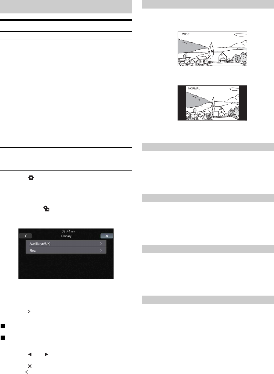
Display Setup Operation
1
Touch [] on the Home screen.
The Setup main screen is displayed.
2
Touch [Display].
The Display Setup screen appears.
•You can display the Display Setup screen from each application
screen. Touch [] on any application screen (video mode).
3
Touch the desired application.
•“Auxiliary (AUX)” can be selected while in AUX mode.
•The camera names set under the “Camera” settings are
displayed. The camera names are not displayed when “Off” is
set (page 22).
4
Touch [] of the desired item.
Settable items differ depending on the application.
[Auxiliary (AUX)]:
Display Mode / Brightness / Color / Contrast / Sharpness
[Camera]:
Brightness / Color / Contrast
5
Touch [] or [] to change its setting.
6
Touch [] to return to the main application screen.
Touch [] to return to the previous screen.
•Immediately after changing the settings of Display Setup (While the
system is writing data automatically) do not turn the ignition key to
OFF. Otherwise, the settings may not be changed.
Setting item: Display Mode
Setting contents: WIDE (Initial setting) / NORMAL
In WIDE mode, the picture is stretched horizontally to fill the
entire display.
In NORMAL mode, the monitor displays a normal picture at the
center of the screen with a vertical black band at each side.
Setting item: Brightness
Setting contents: -15 to +15 (Initial setting: 0)
You can adjust the brightness between MIN (-15) and MAX
(+15). When it reaches the minimum or maximum point, the
display shows “MIN” or “MAX” respectively.
Setting item: Color
Setting contents: -15 to +15 (Initial setting: 0)
You can adjust the Color between MIN (-15) and MAX (+15).
When it reaches the minimum or maximum point, the display
shows “MIN” or “MAX” respectively.
Setting item: Contrast
Setting contents: -15 to +15 (Initial setting: 0)
You can adjust the contrast between MIN (-15) and MAX (+15).
When it reaches the minimum or maximum point, the display
shows “MIN” or “MAX” respectively.
Setting item: Sharpness
Setting contents: -3 to +3 (Initial setting: 0)
Picture quality adjustment range is -3 to +3. “SOFT” and “HARD”
appear as the minimum and maximum values.
Display Setup
To display the Display Setup Menu screen:
Your vehicle must be parked with the ignition key in the ACC or
ON position. To do this, follow the procedures below.
1 Bring your vehicle to a complete stop at a safe
location. Engage the parking brake.
2 Release the parking brake. (For safety, release the
parking brake while depressing the foot brake pedal).
3 Engage the parking brake again.
•For automatic transmission vehicles, place the transmission lever
in the Park position.
Now, the locking system for the Setup operation has been
released. Engaging the parking brake can reactivate the Display
Setup Menu, as long as the car’s ignition has not been turned off.
It is not necessary to repeat the above procedure (1 through 3) of
“To display the Display Setup Menu screen.”
Each time the ignition is turned OFF, perform the procedure of “To
display the Display Setup Menu screen.”
The following steps 1 to 6 are common operations to each
“Setting item” of Display Setup. Refer to each section for
details.
Switching Display Modes
Adjusting Brightness
Adjusting Color of Picture
Adjusting Image Contrast
Adjusting Picture Quality
20-EN
When adjusting Camera, you can store the settings made for “Adjusting
Brightness, Color, and Contrast”.
Setting item: Preset1 / Preset2
1 After completing “Adjusting Brightness, Color, and
Contrast” (page 19), touch and hold [Preset1] or
[Preset2] to save the settings.
2 Touch [Preset1] or [Preset2] to call the saved settings.
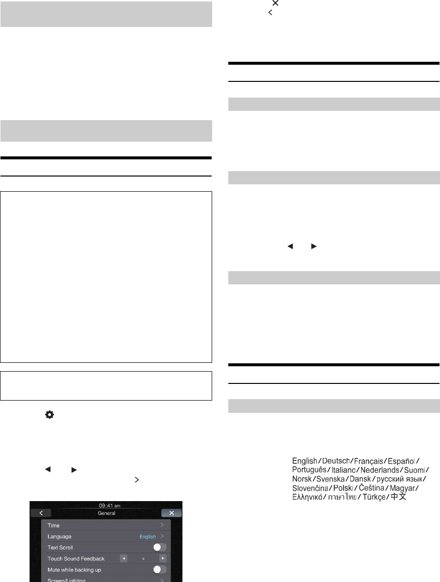
General Setup Operation
1
Touch [] on the Home screen.
The Setup main screen is displayed.
2
Touch [General].
The General Setup screen appears.
3
Touch [] or [] etc., of the desired item to change
its setting. For items that have “ ,” touch the item to
display the screen for the next hierarchy.
Setting items: Time / Language / Text Scroll / Touch Sound
Feedback / Mute while backing up / Screen /
Lighting / About / Demo mode
•Depending on the item, repeat step 3.
•Depending on the setting, displayed items may differ.
4
Touch [] to return to the main application screen.
Touch [] to return to the previous screen.
•Immediately after changing the settings of General Setup (While the
system is writing data automatically) do not turn the ignition key to
OFF. Otherwise, the settings may not be changed.
Time Setting
You can select the clock display type, 12-hour or 24-hour, depending on
your preference.
Setting item: Clock Mode
Setting contents: 12h (Initial setting) / 24h
Setting item: Clock Adjust
Additional items: Hour / Minute
Setting contents: 1-12 or 0-23 / 0-59
•Touch and hold [] or [] to run through a change sequence
automatically.
Setting item: Daylight Saving
Setting contents: ON / OFF (Initial setting)
Language Setting
The Setup menu, feedback information, etc. for this unit can be changed
to appear in the selected language.
Setting item: Language
Setting contents:
•Touch [OK] to confirm the language and display the screen in the
specified language.
Saving and calling the adjusted picture
quality
General Setup
To display the General Setup Menu screen:
Your vehicle must be parked with the ignition key in the ACC or
ON position. To do this, follow the procedures below.
1 Bring your vehicle to a complete stop at a safe
location. Engage the parking brake.
2 Release the parking brake. (For safety, release the
parking brake while depressing the foot brake pedal).
3 Engage the parking brake again.
•For automatic transmission vehicles, place the transmission lever
in the Park position.
Now, the locking system for the General mode operation has
been released. Engaging the parking brake can reactivate the
General Setup Menu, as long as the car’s ignition has not been
turned off. It is not necessary to repeat the above procedure
(1 through 3) of “To display the General mode screen.”
Each time the ignition is turned OFF, perform the procedure of “To
display the General mode screen.”
The following steps 1 to 4 are common operations to each
“Setting item” of General Setup. Refer to each section for details.
Setting the Clock Display
Setting the Time
Hour: Adjust the hour.
Minute: Adjust the minute.
Setting the Daylight Saving Time
ON: Turn Daylight Saving Time mode ON. The time
advances by one hour for areas observing Daylight
Saving Time.
OFF: Return to the ordinary time.
Setting the Menu Language

21-EN
Text Scroll Setting
The text messages in the audio screen are scrolled.
Setting item: Text Scroll
Setting contents: OFF (Initial setting) / ON
Key Sound Setting
You can change the volume of the sound heard when a button is
touched.
Setting item: Touch Sound Feedback
Setting contents: 0 to 7 (Initial setting: 4)
Setting Mute when Reversing
You can set whether to mute the playing music when the gear lever is
moved to the reverse (R) position.
Setting item: Mute while backing up
Setting contents: OFF (Initial setting) / ON
Screen/Lighting Setting
Backlighting is provided by LEDs behind the liquid crystal panel. The
illumination control adjusts the brightness of the backlighting based on
the car's ambient lighting for easier viewing.
Setting item: Dimmer
Setting contents: Auto (Initial setting) / On / Off
•When “Auto” or “On” is set, the setting is also applied for the button
lighting in “Button Backlighting Adjustment” (page 21), and
“Display Backlighting Adjustment” (page 21).
You can adjust the brightness of the button lighting at night with the
dimmer.
Setting item: Key Illumination Level
Setting level: -2 to +2 (Initial setting: 0)
You can adjust the brightness of the backlight. This function could be
used, for instance, to change the screen brightness while traveling at
night.
Setting item: Screen Dimmer Level
Setting content: -15 to +15 (Initial setting: 0)
You can adjust the level between MIN (-15) and MAX (+15).
When it reaches the minimum or maximum point, the display
shows “MIN” or “MAX” respectively.
You can set the image file for the opening screen. Copy your desired
image file from a Flash Memory device.
Setting item: Opening Customization
Setting contents: Default (Initial setting) / User
The file selected in the User mode will be copied according to the
following procedure.
1
Connect the Flash Memory device which contains
the BMP file to be copied to the unit.
2
After the confirmation message is displayed, touch
[OK].
The Opening image is changed.
Compatible image files
About iLX-107
Touch [About] on the General setup menu in step 3. Refer to “General
Setup Operation” (page 20).
You can view the model name, serial number, version information of
this product and BLUETOOTH information. Make note of the version
information and refer to it whenever you contact Alpine Tech Support or
an Alpine-authorized dealer.
Contents: iLX-107 (model name) / Serial Number / Firmware
Version / Bluetooth Device Name / Bluetooth Device
Address
Setting the Scroll
OFF: Turns off the scroll mode.
ON: Turns on the Auto scroll mode. Scroll display is repeated
while the vehicle is parked.
Adjusting the Operating Sound
Setting the Brightness of the Backlighting
Auto: Adjust the brightness of the background illumination of
the monitor automatically to the brightness of the car
interior.
On: Keep the background illumination of the monitor dark.
Off: Deactivate Auto Dimmer mode to keep the background
illumination of the monitor bright.
Button Backlighting Adjustment
Display Backlighting Adjustment
Changing the Opening Image
File format: BMP
Image size: 800 × 480 pixels, RGB 24 bit or less
Folder Name: OPENINGFILE
File Name: openingfile.bmp
Displaying the Product Information
22-EN
You can initialize all data, to restore the factory settings. Remove the
USB Flash memory, from the system before operation
Setting item: Clear All Settings
1
Touch [RESET] of “Clear All Settings”.
2
After the confirmation message appears, touch
[OK].
The system starts initialization.
•Do not turn on/off the power, change the ignition key position or
remove the screen panel until system restart is completed.
Demonstration Setup
[Demo mode] is selected on the General setup menu in step 3. Refer to
“General Setup Operation” (page 20).
This unit has a Demonstration feature for the display. To start demo
mode, set Demo mode to ON.
Setting item: Demo mode
Setting contents: OFF (Initial setting) / ON
•If you perform an operation during the Demo mode, the
demonstration is temporarily stopped.
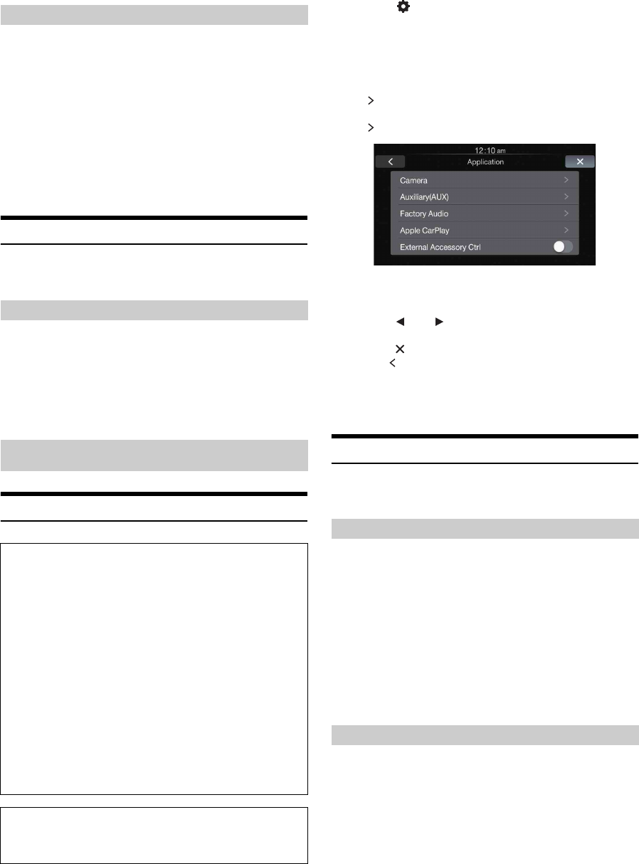
Application Setup Operation
1
Touch [] on the Home screen.
The Setup main screen is displayed.
2
Touch [Application].
The Application Setup screen appears.
3
Select the desired item.
If “ ” appears, there is another hierarchy level. Touch the
desired item.
If “ ” does not appear, proceed to step 4.
Setting items: Camera / Auxiliary (AUX) / Factory Audio / Apple
CarPlay / External Accessory Ctrl
4
Touch [] or [] etc., to change its setting.
5
Touch [] to return to the main application screen.
Touch [] to return to the previous screen.
•Immediately after changing the Application Setup (while the system
is writing data automatically) do not turn the ignition key to OFF.
Otherwise, the settings may not be changed.
Camera Setting
[Camera] is selected on the Application setup menu in step 3. Refer to
“Application Setup Operation” (page 22).
With an optional camera connected, its video is output to the monitor.
When the camera is connected, set this item.
Setting item: Position
Setting contents: Off (Initial setting) / Front / Side / Rear
After selecting “Rear”, “Front” or “Side” in the
“Position” setting, touch [Position], the following
additional items can be adjusted.
When the camera is connected, the video input signal type can be
selected.
Further setting item: Camera Signal
Setting contents: NTSC (Initial setting) / PAL
Initializing the System
Canceling the Demonstration
Application Setup
To display the Application Setup Menu screen:
Your vehicle must be parked with the ignition key in the ACC or
ON position. To do this, follow the procedures below.
1 Bring your vehicle to a complete stop at a safe
location. Engage the parking brake.
2 Release the parking brake. (For safety, release the
parking brake while depressing the foot brake pedal).
3 Engage the parking brake again.
•For automatic transmission vehicles, place the transmission lever
in the Park position.
Now, the locking system for the Setup operation has been
released. Engaging the parking brake can reactivate the
Application Setup Menu, as long as the car’s ignition has not
been turned off. It is not necessary to repeat the above procedure
(1 through 3) of “To display the Application Setup Menu screen”.
Each time the ignition is turned OFF, perform the procedure of “To
display the Application Setup Menu screen”.
The following steps 1 to 5 are common operations to each
“Setting item” of Application Setup. Refer to each section for
details.
Setting the Camera Input
Front: Front camera
Side: Side camera
Rear: Rear camera
Setting the Camera Signal Input
NTSC/PAL: Choose the video input signal type manually.
23-EN
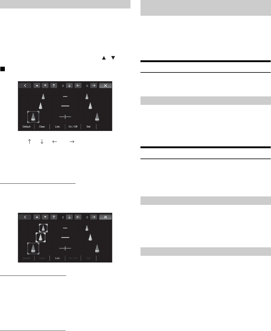
If you select “Rear,” you can adjust the camera guide position.
Setting item: Guide Adjustment
1
Touch [Guide Adjustment].
The camera guide adjustment screen is displayed.
2
Touch the guide you intend to adjust.
Guide line can also be selected by touching [] [].
Display example for rear camera mode
3
Touch [], [], [] or [] to adjust the position
of the guide.
•Touching [Clear] clears adjustments and returns to the setting
before guide line alteration.
4
After the adjustment is completed, touch [Set].
Adjusting guides simultaneously
1
Touch [Link].
The 3 vertical guides of the currently-selected guide link
together, allowing them to be adjusted simultaneously.
Turning guide display On/Off
Turning the selected guide off.
1
Touch [On/Off].
The currently selected guide will turn off.
2
To turn the guide on, touch [On/Off] again.
•Guides that are turned off are still adjustable.
Returning guides to default.
1
Touch [Default].
A message window will appear.
2
Touch [OK].
Adjusted values will return to default settings.
You can set whether to display the rear camera image when the gear
lever is moved to the reverse (R) position while the unit is turned off.
You can select this item only when Camera Select is “Rear.”
Setting item: Interrupt (Power OFF)
Setting contents: ON (Initial setting) / OFF
Auxiliary (AUX) Setting
[Auxiliary (AUX)] is selected on the Application setup menu in step 3.
Refer to “Application Setup Operation” (page 22).
Setting item: AUX In
Setting contents: OFF / ON (Initial setting)
Factory System Setup
[Factory Audio] is selected on the Application Setup Menu screen in
step 3. See “Application Setup Operation” (page 22).
•This setting item not displayed when no iDataLink module is
connected.
You can set whether the following source icon from iDataLink module
in the Home screen is available.
Setting item: USB/iPod (Initial setting: OFF) / SiriusXM (Initial
setting: OFF)
Setting contents: ON / OFF
You can change the setting of the connected iDataLink module.
Setting item: Maestro Module
•Depending on the iDataLink module, the setting contents may differ.
Adjusting the Rear Camera Guide Camera Interrupt Setting (Power OFF
Mode) (Rear Camera Only)
Setting the Auxiliary (AUX) Mode
OFF: AUX source is not displayed.
ON: AUX source is displayed and the video input signal type
(NTSC or PAL) will be automatically selected.
Setting the Source Category
Setting the Maestro Module
24-EN
Apple CarPlay Setting
[Apple CarPlay] is selected on the Application setup menu in step 3.
Refer to “Application Setup Operation” (page 22).
You can enjoy wireless connection between iLX-107 and iPhone instead
of USB connection in Apple CarPlay mode.
Setting item: WLAN
Setting contents: OFF / ON (Initial setting)
•After the above setting, turn the ignition key off (ACC OFF) and on
(ACC ON) again.
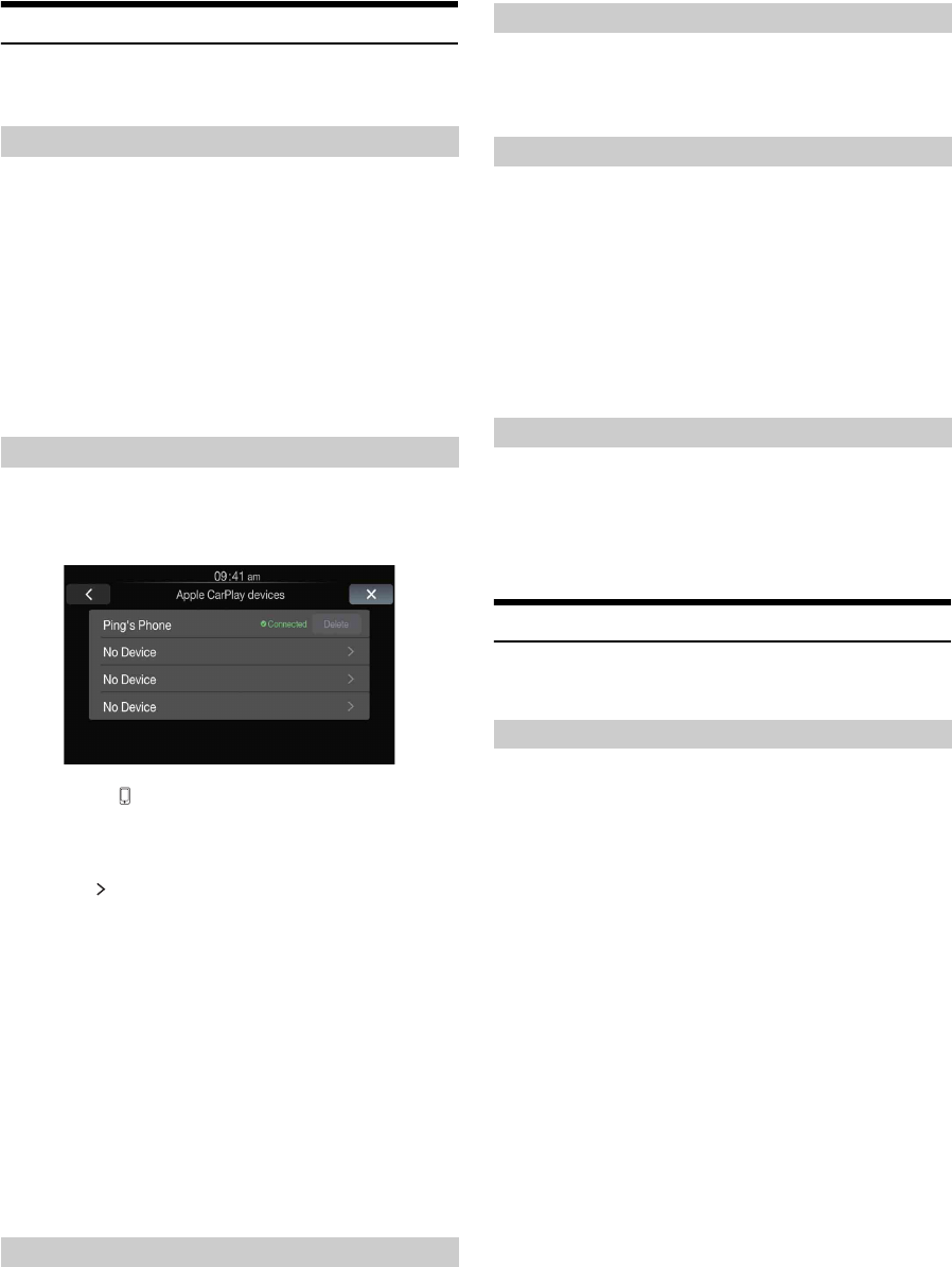
After turning on the “WLAN”, this item can be carried out.
This function is used when an Apple CarPlay Device is searched and
connected from this unit, or an Apple CarPlay Device is registered.
•You can touch [ ] on Home screen to change to Apple CarPlay
devices list while “WLAN” is ON.
•When no iPhone is connected, you can also change to Apple CarPlay
devices list by pressing and holding Siri button.
1
Touch [] of No Device to search for an Apple
CarPlay device.
Make sure the iPhone is on Bluetooth devices screen for
paring.
A maximum of 10 Apple CarPlay devices can be searched.
•If a confirmation prompted, touch [OK] to disconnect the
currently connecting iPhone and continue to search other Apple
CarPlay devices. Touch [Cancel] to keep the current connection
and stop the search.
2
Touch a desired Apple CarPlay device to connect
and then follow the prompt to operate.
•If an Apple CarPlay device has been registered, touch
[Connect] directly.
•Touch [Delete] to omit registered Apple CarPlay device.
However, you cannot delete the connecting Apple CarPlay
device.
This setting influences Apple CarPlay mode.
Setting item: Steering wheel
Setting contents: Left (Initial setting) / Right
You can turn on or off the Siri Microphone Effect.
Setting item: Microphone EC / NR
Setting contents : ON (Initial setting:) / OFF
You can select which speaker in the car will output the audio from the
phone.
Setting item: Call Speaker Select
Setting contents: All (Initial setting) / Front L / Front R / Front LR
You can adjust the transmit volume.
Setting item: Microphone Level
Setting contents: 1 to 11 (Initial setting: 5)
•The setting cannot be adjusted during a phone call. Adjust the setting
before placing a call.
External Accessory Control Setup
[External Accessory Ctrl] is selected on the Application Setup Menu
screen in step 3. See “Application Setup Operation” (page 22).
When you have connected the optional External Accessory Control
module, set this setting to “ON” to turn the headlights ON/OFF or
adjust the air suspension from this unit.
Setting item: External Accessory Ctrl
Setting contents: OFF (Initial setting) / ON
•When set to “ON,” the External Parts icon is displayed on the main
screen.
•For details on the External Accessory screen and its operation, see
“External Accessory Control Operation” (page 27).
Setting the WLAN ON/OFF
OFF: WLAN function is not available.
ON: WLAN function is available. At this time, an iPhone
can be connected to this unit via WLAN. After
connected via WLAN, you can enjoy Apple
CarPlay on iLX-107 wirelessly.
Registering the Apple CarPlay Device
Steering wheel Setting
Setting the Siri Microphone Effect
Selecting the Output Speaker
All: The sound is output from all speakers in car.
Front L: The sound is only output from the front left speaker.
Front R: The sound is only output from the front right
speaker.
Front LR: The sound is output from the front left and front
right speakers.
Adjusting the Microphone Level
Setting the External Accessory Control
25-EN
This unit allows communication with the vehicle’s iDataLink module,
when available. This data gives status on various vehicle modes as well
as the ability to control certain vehicle operations.
When you use iDataLink mode, set each setting to “ON” in “Setting the
Source Category” (page 23).
•Available functions differ depending on your vehicle. For details,
refer to your vehicle’s instruction manual.
About Audio Interrupt
Audio Interrupt is the function that outputs sound from the unit when
Voice Information (audio reading from the phone book, etc.)* from the
vehicle occurs.
•The Audio Interrupt function of the vehicle differs depending on the
type and grade of the vehicle.
* For your safety, when interrupted with Voice Information, you cannot
operate the buttons on the front panel or the touch buttons on the
display, except for some operations.
- The operating restrictions may differ depending on which mode
the unit is in during Voice Information.
- You can use the / (DOWN/UP) button to control the volume of
Voice Information.
Access to iDataLink Mode
You can check the car’s status, set the air conditioning, etc.
1
Press the Home button.
The Home screen is displayed.
2
Touch the desired tag.
Select item: Climate / Gauges / Parking Sensor / Vehicle Info.
•The displayed tag options differ depending on the type of vehicle.
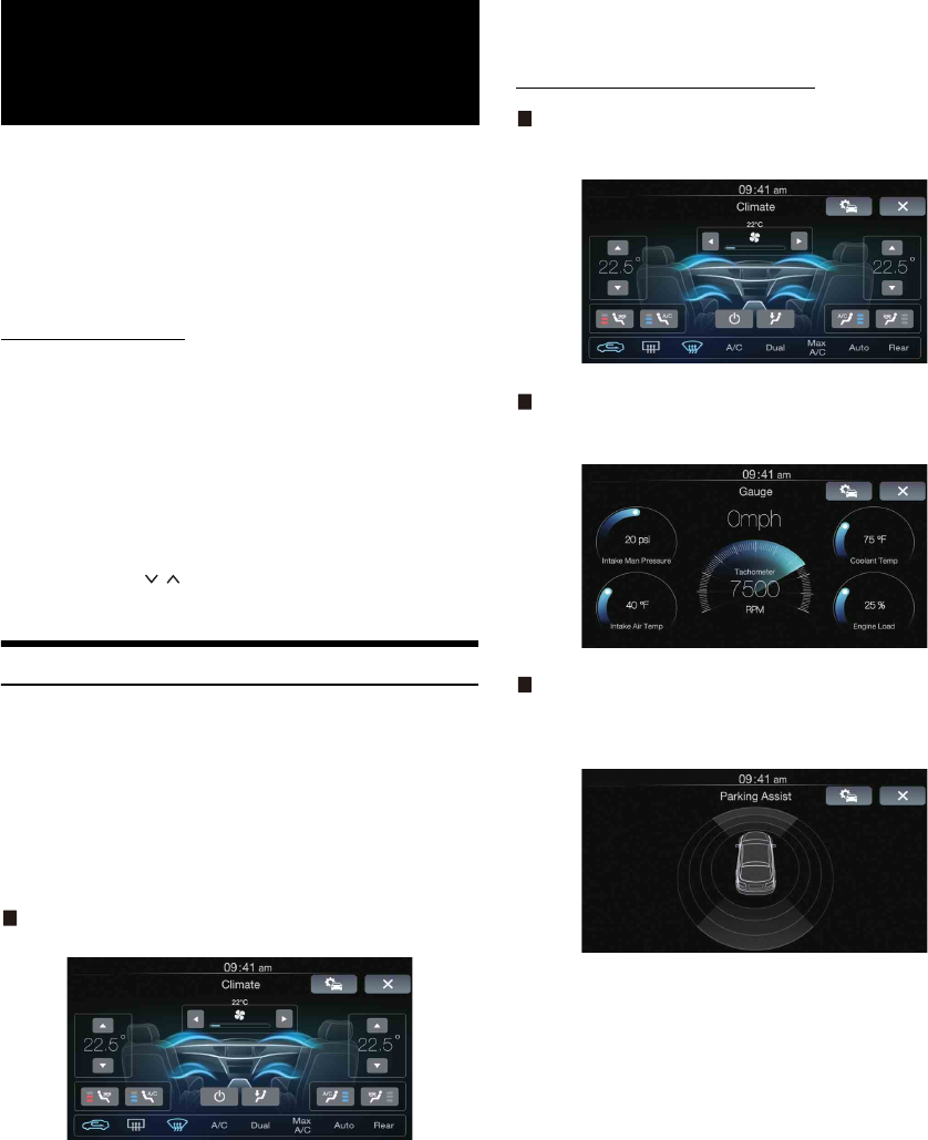
Climate screen example
3
Adjust or confirm the item/information accordingly.
•Operable functions and displays may differ depending on the vehicle.
iDataLink Function Screen example
Climate screen example
You can control the temperature inside the vehicle, etc.
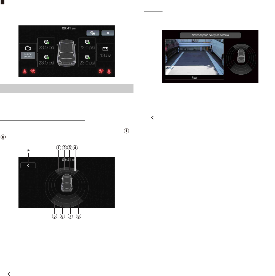
Gauges screen example
You can check the vehicle's speed, the engine's rotation speed, etc.
Parking sensor screen example
You can check the distance from the front and rear of the vehicle to an
obstacle.
•If the car sensor detects an obstacle, the screen automatically
changes to the Parking sensor screen. For details, see “About
Parking Sensor screen” (page 26).
iDataLink
Operation
26-EN
Vehicle Information screen example
You can check for open doors, check the tire pressure, the battery life,
etc. for the vehicle.
The Parking sensor screen turns on when the front or rear sensor on
your vehicle detects an obstacle within a certain distance.
Parking Sensor Full screen example
When the front or rear sensor detects an obstacle within a certain
distance, the Parking Sensor screen is displayed, and the indicator ( -
) that corresponds with that area lights up.
Indicator colors when an obstacle is detected.
Red: close distance
Orange: medium distance
Yellow: long distance
• Depending on the speed of the vehicle, when moving faster than a
certain speed, the Parking Sensor screen may not be displayed.
• Vehicles that do not have the obstacle detection sensor cannot use
this function.
*[] is displayed only when the Front camera or Rear camera is
interlocked.
Parking Sensor Camera interlock screen example (Rear
camera)
You can check for obstacles through an interlocked camera image by
connecting a Front or Rear Camera.
• Touch the Camera image area to switch to the Camera full screen.
(While displaying the Camera full screen, touch the Camera screen,
then touch [Sensor] to return to the Parking Sensor Camera interlock
screen.)
• Touch the car icon to switch to the Parking sensor full screen. (Touch
[] on the Parking Sensor full screen to return to the Parking Sensor
Camera interlock display.)
• To use this function, set the Camera Select setting to “Front/Other”
or “Rear.” For details, see “Setting the Camera Input” (page 22).
About Parking Sensor screen
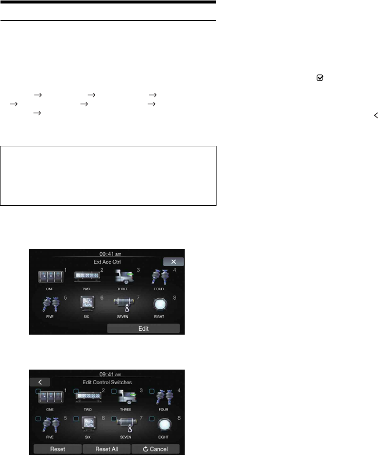
27-EN
External Accessory Control Operation
You can set the headlights to ON/OFF or adjust the air suspension from
this unit by connecting the optional External Accessory Control
module.
• In order to keep external accessory control outputs on during the
ignition cycle, please change “Accessory During Crank” to “On”.
Otherwise all switches will be turned off.
[Setup] [Application] [Factory Audio] [Maestro Module]
[Maestro Features] [Maestro Module] [Accessory During
Crank] “On”
The following explains how to edit the control switches, because the
functions that can be controlled differ depending on the type of vehicle.
1
Touch [Ext Acc Ctrl] in the Home screen to
activate External Accessory screen.
The External Accessory screen is displayed.
2
Touch [Edit].
The Edit Control Switches screen is displayed.
3
Edit each switch.
When changing an icon:
Touch the icon, and select your desired icon from the Icon
Type list. After selecting the icon, set the Output Type
(Timing)* for each function.
* The Output Type (Timing) sets the operating time for that
function when you touch the icon on the External Accessory
screen.
When changing the name:
Touch the icon name, then input characters into Edit Name
(Keypad). You can also select a basic name from the [Template] of
the Keypad. (When a basic name is selected from the Template, the
icon will be changed according to the basic name.)
When changing the layout of the switches:
Drag and drop an icon to the desired location.
To revert to a default icon:
Touch the check box “ ” of the icon that you want to revert to
default, and then touch [Reset]. If you touch [Reset All], all icons
revert to default icons.
4
After editing is complete, touch [] (Back).
5
After the caption for the confirmation is displayed,
touch [OK].
• If you touch [Cancel] while editing, the edits are reset and the screen
returns to the previous Edit screen.
You cannot edit the External Accessory screen while
driving.
Your vehicle must be parked with the ignition key in the ACC or ON
position. For details, see “To display the Application Setup Menu
screen:” in “Application Setup” (page 22).
Pulse: The operating time when you touch the icon. (Select from
11 steps, ranging 0.5 sec. to 10 sec.)
Latch: Switch On/Off by touching the icon.
Momentary: Operating time lasts from when an icon is touched to
when it is released.

28-EN
Product Software Update
This product uses software that can be updated through a Flash Memory
device. Download the software from the Alpine website and update the
product using the Flash Memory device.
Updating this product
Check the Alpine website for details on updating.
http://www.alpine-usa.com
Important information on the software
About the software license of the product
The software installed in the product contains opensource software.
See the following Alpine website for details on the open source
software.
http://www.alpine.com/e/oss/download
In Case of Difficulty
Basic
No function or display.
• Vehicle’s ignition is off.
- If connected according to the instructions, the unit will not
operate with the vehicle’s ignition off.
• Improper power lead connections.
- Check power lead connections.
•Blown fuse.
- Check the fuse of the unit; replace with the proper value if
necessary.
• Internal micro-computer malfunctioned due to interference
noise, etc.
- Turn the ignition key off, and then set to ON again.
No sound or unnatural sound.
• Incorrect setting of volume/balance/fader controls.
- Readjust the controls.
• Connections are not properly or securely made.
- Check the connections and firmly connect.
Screen not displayed.
• Brightness/Contrast control is set at the minimum position.
- Adjust the Brightness/Contrast control.
• Temperature in the vehicle is too low.
- Increase the vehicle’s interior temperature to operation
temperature range.
• Connections to the Auxiliary Device are not securely made.
- Check the connections and firmly connect.
• The Parking Brake Lead is not connected.
• The Parking Brake is not engaged.
- Connect the Parking Brake Lead, then engage the Parking
Brake.
Movement of displayed picture is abnormal.
• Temperature in the vehicle is too high.
- Allow the vehicle’s interior temperature to cool.
Screen changed automatically.
• Demonstration function is set to “ON”.
- Set the Demonstration function to “OFF”. (Page 22)
Radio
Unable to receive stations.
• No antenna, or open connection in the antenna cable.
- Make sure the antenna is properly connected; replace the
antenna or cable if necessary.
Unable to tune stations in the seek mode.
• You are in a weak signal area.
- Make sure the tuner is in DX mode.
• If the area you are in is a primary signal area, the antenna may
not be grounded and connected properly.
- Check your antenna connections; make sure the antenna is
properly grounded at its mounting location.
• The antenna may not be the proper length.
- Make sure the antenna is fully extended; if broken, replace the
antenna with a new one.
Broadcast is noisy.
• The antenna is not the proper length.
- Extend the antenna fully; replace it if it is broken.
• The antenna is poorly grounded.
-
Make sure the antenna is grounded properly at its mounting location.
• The station signal is weak and noisy.
- If above solution does not work, tune in another station.
If this Message Appears
Various messages are displayed on the screen during operation. In
addition to the messages telling you the current status or providing
guidance for the next operation, there are also the following error
messages. If one of these error messages is displayed, carefully follow
the instructions in the solution column.
System
Unable to operate while driving.
• A setup operation, etc., was carried out while the vehicle was
running.
- Move the vehicle to a safe location, stop, and engage the
parking brake, then carry out this operation.
USB current error.
• Abnormal current is run to the USB connector device.
- Turn the ignition key off, and then set to ON again.
- Attempt to connect another iPhone/Flash Memory device.
Device no response.
• There is no response for the connected Flash Memory device.
- Attempt to connect another Flash Memory device.
Information
If you encounter a problem, please turn the power off, then on again.
If the unit is still not functioning normally, please review the items in
the following checklist. This guide will help you isolate the problem
if the unit is at fault. Otherwise, make sure the rest of your system is
properly connected, or then consult your authorized Alpine dealer.

29-EN
Audio/Visual
Connected USB Device is not supported.
• An iPhone that is not supported by the unit is connected.
- Connect an iPhone that is supported by the unit.
- Reset the iPhone.
• A USB device that is not supported by the unit is connected.
- Attempt to connect another Flash Memory device.
• Communication error.
- Turn the ignition key off, and then set to ON again.
- Check the display by reconnecting between the iPhone and the
unit, using the Lightning to USB Cable.
- Check the display by reconnecting between the Flash Memory
device and the unit.
• Caused by the iPhone Software Version not being compatible
with this unit.
- Update the iPhone Software Version to be compatible with this
unit.
• The iPhone is not verified.
- Change another iPhone.
iDataLink
CAN Communication error
• Communication error.
- Check the iDataLink module connection.
Specifications
MONITOR SECTION
FM TUNER SECTION
AM TUNER SECTION
USB SECTION
GENERAL
• Power output: measured at 4 Ohms and ≤ 1% THD+N
• S/N: 80 dBA (reference: 1 W into 4 Ohms)
CHASSIS SIZE
•Due to continuous product improvement, specifications and design
are subject to change without notice.
•The LCD panel is manufactured using an extremely high precision
manufacturing technology. Its effective pixel ratio is over 99.99%.
This means that there is a possibility that 0.01% of the pixels could
be either always ON or OFF.
Screen Size 7.0"
LCD Type Transparent type TN LCD
Operation System TFT active matrix
Number of Picture Elements 1,152,000 pcs. (800 × 480 × 3
(RGB))
Effective Number of Picture Elements
99% or more
Illumination System LED
Tuning Range 87.7 – 107.9 MHz
Mono Usable Sensitivity 9.3 dBf (0.8 µV/75 ohms)
50 dB Quieting Sensitivity 13.5 dBf (1.3 µV/75 ohms)
Alternate Channel Selectivity 80 dB
Signal-to-Noise Ratio 60 dB
Stereo Separation 35 dB
Capture Ratio 2.0 dB
Tuning Range 530 – 1,710 kHz
Sensitivity (IEC Standard) 22.5 µV/27.0 dBf
USB requirements USB 1.1/2.0
Power Requirement 14.4 V DC
(11–16 V allowable)
Operating temperature -4°F to +140°F
(-20°C to + 60°C)
Power Output 18 W RMS × 4
Weight 1.23 kg (2 1bs 11 oz)
Audio output level
Preout (Front, Rear): 2V/10k ohms (max.)
Preout (Subwoofer): 2V/10k ohms (max.)
Width 178 mm (7")
Height 100 mm (3-7/8")
Depth 155 mm (6-1/8")

30-EN
Installation and Connections
Before installing or connecting the unit, please read the
following and pages 5 to 6 of this manual thoroughly for
proper use.
Warning
MAKE THE CORRECT CONNECTIONS.
Failure to make the proper connections may result in fire or product
damage.
USE ONLY IN CARS WITH A 12 VOLT NEGATIVE GROUND.
(Check with your dealer if you are not sure.) Failure to do so may
result in fire, etc.
BEFORE WIRING, DISCONNECT THE CABLE FROM THE
NEGATIVE BATTERY TERMINAL.
Failure to do so may result in electric shock or injury due to
electrical shorts.
DO NOT ALLOW CABLES TO BECOME ENTANGLED IN
SURROUNDING OBJECTS.
Arrange wiring and cables in compliance with the manual to
prevent obstructions when driving. Cables or wiring that obstruct or
hang up on places such as the steering wheel, gear lever, brake
pedals, etc. can be extremely hazardous.
DO NOT SPLICE INTO ELECTRICAL CABLES.
Never cut away cable insulation to supply power to other
equipment. Doing so will exceed the current carrying capacity of
the wire and result in fire or electric shock.
DO NOT DAMAGE PIPE OR WIRING WHEN DRILLING
HOLES.
When drilling holes in the chassis for installation, take precautions
so as not to contact, damage or obstruct pipes, fuel lines, tanks or
electrical wiring. Failure to take such precautions may result in fire.
DO NOT USE BOLTS OR NUTS IN THE BRAKE OR STEERING
SYSTEMS TO MAKE GROUND CONNECTIONS.
Bolts or nuts used for the brake or steering systems (or any other
safety-related system), or tanks should NEVER be used for
installations or ground connections. Using such parts could disable
control of the vehicle and cause fire etc.
KEEP SMALL OBJECTS SUCH AS SCREWS OUT OF THE
REACH OF CHILDREN.
Swallowing them may result in serious injury. If swallowed,
consult a physician immediately.
DO NOT INSTALL IN LOCATIONS WHICH MIGHT HINDER
VEHICLE OPERATION, SUCH AS THE STEERING WHEEL OR
GEARSHIFT.
Doing so may obstruct forward vision or hamper movement etc.
and results in serious accident.
Caution
HAVE THE WIRING AND INSTALLATION DONE BY EXPERTS.
The wiring and installation of this unit requires special technical
skill and experience. To ensure safety, always contact the dealer
where you purchased this product to have the work done.
USE SPECIFIED ACCESSORY PARTS AND INSTALL THEM
SECURELY.
Be sure to use only the specified accessory parts. Use of other than
designated parts may damage this unit internally or may not
securely install the unit in place. This may cause parts to become
loose resulting in hazards or product failure.
ARRANGE THE WIRING SO IT IS NOT CRIMPED OR
PINCHED BY A SHARP METAL EDGE.
Route the cables and wiring away from moving parts (like the seat
rails) or sharp or pointed edges. This will prevent crimping and
damage to the wiring. If wiring passes through a hole in metal, use
a rubber grommet to prevent the wire’s insulation from being cut by
the metal edge of the hole.
DO NOT INSTALL IN LOCATIONS WITH HIGH MOISTURE OR
DUST.
Avoid installing the unit in locations with high incidence of
moisture or dust. Moisture or dust that penetrates into this unit may
result in product failure.
Precautions
• Be sure to disconnect the cable from the (–) battery post before
installing your iLX-107. This will reduce any chance of damage
to the unit in case of a short-circuit.
• Be sure to connect the color coded leads according to the
diagram. Incorrect connections may cause the unit to
malfunction or damage to the vehicle’s electrical system.
• When making connections to the vehicle’s electrical system, be
aware of the factory installed components (e.g. on-board
computer). Do not tap into these leads to provide power for this
unit. When connecting the iLX-107 to the fuse box, make sure
the fuse for the intended circuit of the iLX-107 has the
appropriate amperage. Failure to do so may result in damage to
the unit and/or the vehicle. When in doubt, consult your Alpine
dealer.
• The iLX-107 uses female RCA-type jacks for connection to
other units (e.g. amplifier) having RCA connectors. You may
need an adaptor to connect other units. If so, please contact your
authorized Alpine dealer for assistance.
• Be sure to connect the speaker (–) leads to the speaker (–)
terminal. Never connect left and right channel speaker cables to
each other or to the vehicle body.
• The Display must be completely retracted in the casing when
installing. If it is not, problems may occur.
• When installing in automobiles, make sure the Display can open/
close without coming in contact with the gear shift.
IMPORTANT
Please record the serial number of your unit in the space provided on
the right and keep it as a permanent record. The serial number plate is
located on the bottom of the unit.
SERIAL NUMBER:
INSTALLATION DATE:
INSTALLATION TECHNICIAN:
PLACE OF PURCHASE:
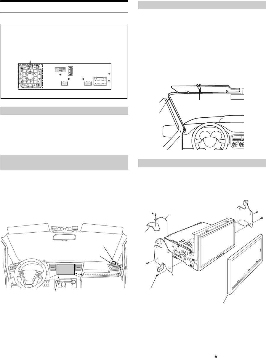
31-EN
Installation
1
Uninstall the car stereo with its mounting bracket.
2
Remove the cables and the mounting bracket
attached to the car stereo.
(The mounting bracket will be used in “Installing the unit”.)
Please mount the GPS Antenna properly as follow procedures to make
sure the unit's perfect performance.
1
Clean the mounting location.
2
Put on the GPS Antenna mounting plate.
3
Mount the GPS Antenna.
•Do not mount the GPS Antenna inside the center console.
- Mount the GPS Antenna on a flat plane of the dash board or rear
tray.
- Make sure the GPS Antenna is not covered (obstructed) by any
metallic surface or object.
•If the GPS Antenna is mounted near the unit, the reception becomes
poor, and the location of your vehicle may not be displayed correctly.
- Mount the GPS Antenna as far away from the unit as possible.
- Bundle the GPS Antenna cable away from the rear of the unit.
•Some types of thermal glass may block the GPS radio frequencies. If
reception is poor with the antenna installed inside the car, try to
mount the antenna outside the car.
For safe use, make sure of the following:
•Location is stable and firm.
•Driver’s view and operations are not obstructed.
•Microphone is located where the driver’s voice can be easily
picked up (for example, on the sun visor).
When you speak into the microphone, you should not have to
change your driving posture. This may cause a distraction,
taking your attention away from safely driving your vehicle.
Carefully consider direction and distance while mounting the
microphone. Confirm that the driver’s voice can be easily picked
up at the selected location.
1
Remove the Face Plate from the unit.
2
Mount the original mounting bracket to the unit
using the supplied screws.
3
Connect all other leads of the unit according to
details described in the “Connections” section
(page 34).
4
Mounting the unit in a car.
*1To securely connect the ground lead, use an already installed screw
on a metal part of the vehicle (marked ( )) or a clean, bare metal
spot on the vehicle’s chassis.
*2Use the removed Face Plate if needed.
Uninstalling the original car stereo
Mounting the GPS Antenna inside the
vehicle
Note on installation
•Do not block the unit’s fan, which would prevent air
circulation. If blocked, heat will accumulate inside the
unit and may cause a fire.
Air Ventialtion hole Rear of the Unit
Antenna mounting plate
GPS Antenna
This unit
Mounting the Microphone.
Installing the Unit
Microphone
Cable clamp
(Sold separately)
Chassis
Screws (M5 × 8) (Included)
Original Mounting Bracket
Ground Lead*1
Face plate (Included)*2

32-EN
Fix the cables carefully. Do not damage them by tucking them
into movable parts, such as a seat rail, or by locating them
against sharp or pointed edges.
Fix the Cables etc.

33-EN
Connection Diagram of SPST Switch (sold separately)
(If the ACC power supply is not available)
•If your vehicle has no ACC power supply, add a SPST (Single-Pole, Single-Throw) switch (sold separately) and fuse (sold separately).
•The diagram and the fuse amperage shown above are in the case when iLX-107 is used individually.
•If the switched power (ignition) lead of the iLX-107 is connected directly to the positive (+) post of the vehicle’s battery, the
iLX-107 draws some current (several hundred milliamperes) even when its switch is placed in the OFF position, and the battery may be discharged.
iLX-107
(Red)
(Yellow)
SPST SW (Optional) FUSE (5A)
(Optional)
FUSE (20A)
(Optional)
Battery
ACC
BATTERY
To prevent external noise from entering the audio system.
•Locate the unit and route the leads at least 10 cm away from the car harness.
•Keep the battery power leads as far away from other leads as possible.
•Connect the ground lead securely to a bare metal spot (remove any paint, dirt or grease if necessary) of the car chassis.
•If you add an optional noise suppressor, connect it as far away from the unit as possible. Your Alpine dealer carries various
noise suppressors, contact them for further information.
•Your Alpine dealer knows best about noise prevention measures so consult your dealer for further information.
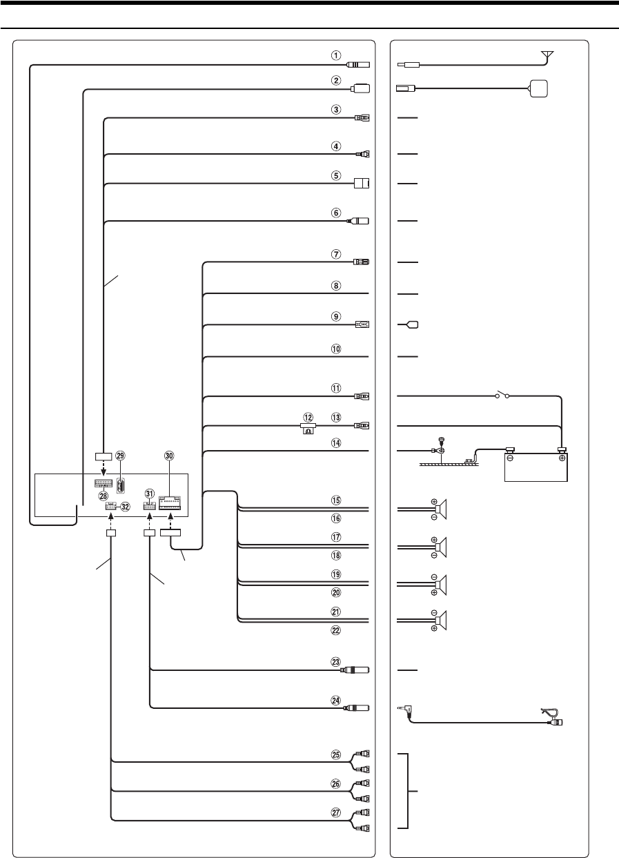
34-EN
Connections
Power cable
W.REMOTE cable
STEERING REMOTE
FRONT OUT
MIC IN
REAR OUT
SUBW
To steering remote control
interface box
Microphone (Included)
To input terminal of amplifier when
adding an external amplifier
PRE OUT cable
Interface cable
SPEED SENSOR
(Green/White)
CAMERA
IDATALINK I/F
AUX INPUT
REMO
(Blue/White)
REVERSE
(Orange/White)
P. AN T
(Blue)
PARKING BRAKE
(Yellow/Blue)
(Green)
(Green/Black)
(White)
(White/Black)
(Gray/Black)
(Gray)
(Violet/Black)
(Violet)
ACC
(Red)
BATT
(Yellow)
GND
(Black)
Vehicle Antenna
GPS Antenna (Included)
To the vehicle speed pulse line
To Front, Rear or Side camera
To iDataLink module
To Video/Audio (R, L) Output
terminal
To amplifier or equalizer
To plus side of the back-up lamp
signal lead of the car
To power antenna
To the parking brake signal lead
Rear Left
Front Left
Front Right
Rear Right
Speakers
Battery
Ignition key
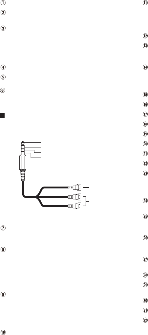
35-EN
Radio Antenna Receptacle
GPS Antenna Receptacle
Connect to GPS antenna (Included).
Speed Sensor Lead (Green/White)
Improper connection of the speed pulse line may cause
important safety features of the vehicle to fail (such as the
brakes or air bags). Such failures may result in an accident
and loss of life. We strongly recommend that the installation
be performed by a trained, authorized Alpine dealer.
CAMERA Input Connector
iDataLink Interface Connector
To iDataLink module.
Video/Audio (R,L) Input Connector (AUX INPUT)
Input the AUX Video/Audio (R,L).
•When you use this connector, an optional AV/RCA interface cable
should be used.
Usable AV/RCA interface cable (4-pole mini AV plug
to 3-RCA)
Wiring convention of this system is as follows:
•Configuration commercially available 4-pole mini AV plugs is not
standardized.
Remote Turn-On Lead (Blue/White)
Connect this lead to the remote turn-on lead of your
amplifier or signal processor.
Reverse Lead (Orange/White)
Connect to the plus side of the car’s reverse lights. These
lights illuminate when the transmission is shifted into reverse
(R).
With this lead properly wired, the video picture
automatically switches to the rear camera whenever the car
is put into reverse (R).
Power Antenna Lead (Blue)
Connect this lead to the +B terminal of your power antenna,
if applicable.
• This lead should be used only for controlling the vehicle’s
power antenna. Do not use this lead to turn on an amplifier or a
signal processor, etc.
Parking Brake Lead (Yellow/Blue)
Connect this lead to the power supply side of parking brake
switch to transmit the parking brake status signals to the
unit.
Switched Power Lead (Ignition) (Red)
Connect this lead to an open terminal on the vehicle’s fuse
box or another unused power source that provides (+) 12V
only when the ignition is turned on or in the accessory
position.
Fuse Holder (15A)
Battery Lead (Yellow)
Connect this lead to the positive (+) post of the vehicle’s
battery.
Ground Lead (Black)
Connect this lead to a good chassis ground on the vehicle.
Make sure the connection is made to bare metal and is
securely fastened using the sheet metal screw provided.
Left Rear (+) Speaker Output Lead (Green)
Left Rear (–) Speaker Output Lead (Green/Black)
Left Front (+) Speaker Output Lead (White)
Left Front (–) Speaker Output Lead (White/Black)
Right Front (–) Speaker Output Lead (Gray/Black)
Right Front (+) Speaker Output Lead (Gray)
Right Rear (–) Speaker Output Lead (Violet/Black)
Right Rear (+) Speaker Output Lead (Violet)
Steering Remote Control Interface Connector
To steering remote control interface box.
For details about connections, consult your nearest Alpine
dealer.
MIC Input Connector
To microphone (Included)
Front Output RCA Connectors
Can be used as Front Output RCA Connectors. RED is right
and WHITE is left.
Rear Output RCA Connectors
Can be used as Rear Output RCA Connectors. RED is right
and WHITE is left.
Subwoofer RCA Connectors
RED is right and WHITE is left.
CAN I/F Connector
USB Connector
To iphone 5 or later.
Power Supply Connector
W.REMOTE Connector
PRE OUT Connector
Yellow
Red
White
Video input
terminal
Audio input
terminal
(R,L)
Audio L (White)
Audio R (Red)
Ground
Video (Yellow)
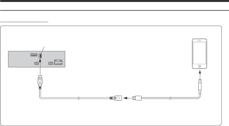
36-EN
System Example
Connection of an iPhone*
•Do not leave an iPhone in a vehicle for a long time. Heat and humidity may damage the iPhone and you may not be able to play it again.
USB Connector
Lightning to USB Cable
(Included with iPhone)
iPhone*
(Sold separately)
USB Extension Cable (Included)
* About iPhone models usable with this unit, refer to Apple CarPlay section (page 12).
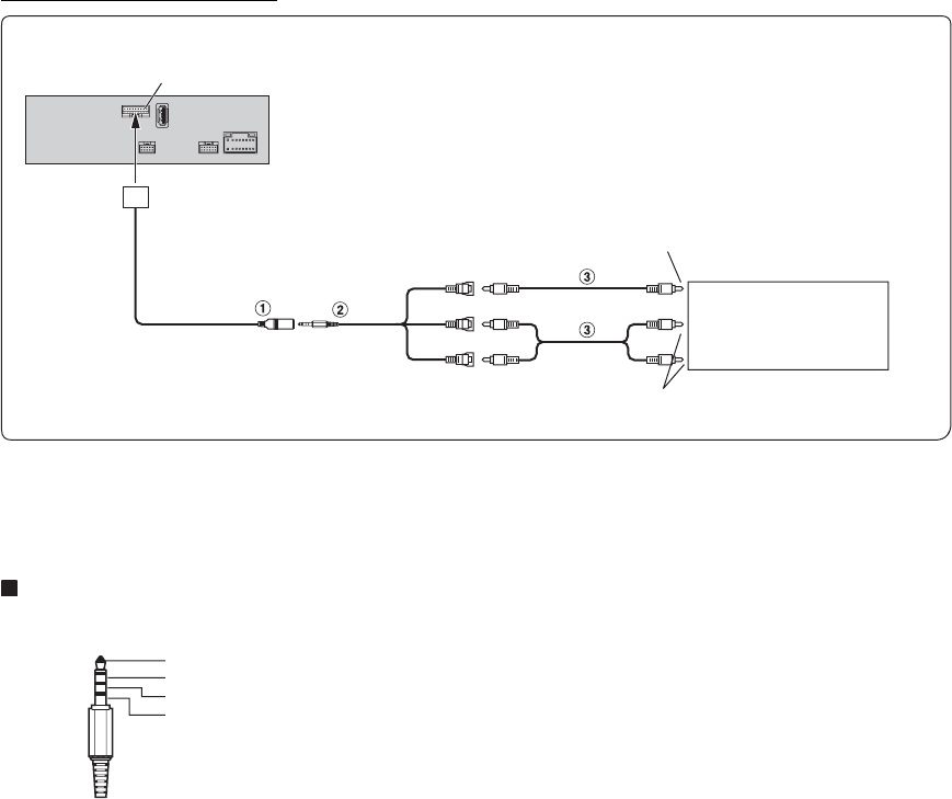
37-EN
Connection of an External device
1Video/Audio Input Connector (AUX INPUT)
•When you use this connector, an optional AV/RCA interface cable
should be used. For details, refer to 2.
2AV/RCA interface cable (4-pole mini AV plug to
3-RCA) (Sold Separately)
Usable 4-pole mini AV plug
Wiring convention of this system is as follows:
•Configuration commercially available 4-pole mini AV plugs is not
standardized.
3RCA Extension Cable (Sold Separately)
(Yellow)
(Red)
(White)
To Video Output Terminal
DVD Player,etc
(sold separately)
To Audio Output Terminal
CAN I/F OUT Connector
Audio L (White)
Audio R (Red)
Ground
Video (Yellow)
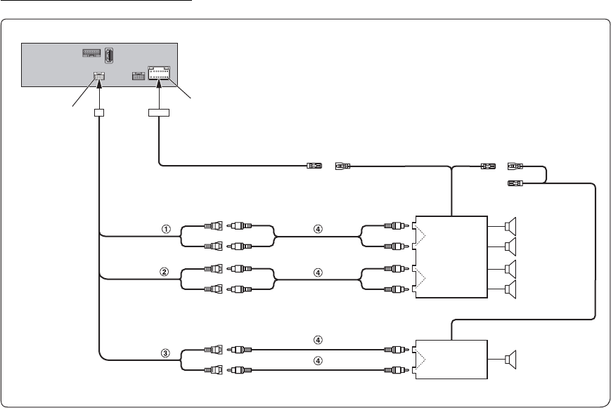
38-EN
Connection of an External Amplifier
1Front Output RCA Connectors
RED is right and WHITE is left.
2Rear Output RCA Connectors
RED is right and WHITE is left.
3Subwoofer RCA Connectors
4RCA Extension Cable (Sold separately)
Power Supply Connector
Amplifier 4 ch (Sold separately)
Input
Input
Front speakers
Rear speakers
REMO
(Blue/White)
Amplifier for subwoofer (Sold separately)
Input Subwoofer
REMOTE ON
(Blue/White)
REMOTE ON
(Blue/White)
PRE OUT
Connector
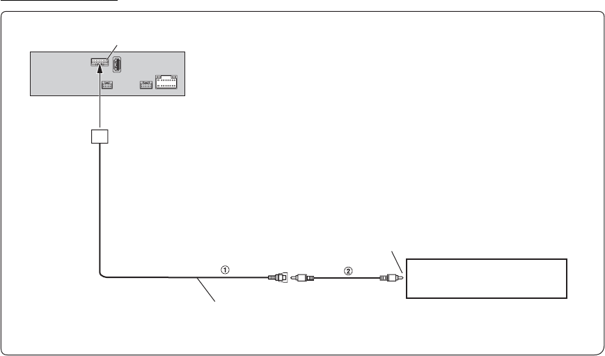
39-EN
Connection of camera
1CAMERA Input Connector
•When a rear camera is used, make sure REVERSE cable is connected
correctly.
2RCA Extension Cable (sold separately)
To Video Output terminal
Camera with RCA video output (sold
separately)
HCE-C155, etc.
CAN I/F Connector
CAMERA Cable

LIMITED WARRANTY
ALPINE ELECTRONICS OF AMERICA, INC. (“Alpine”), is dedicated to quality craftsmanship and is pleased to offer this Warranty. We suggest that
you read it thoroughly. Should you have any questions, please contact your Dealer or contact Alpine at one of the telephone numbers listed below.
PRODUCTS COVERED:
This Warranty covers Car Audio Products and Related
Accessories (“the product”). Products purchased in the Canada
are covered only in the Canada. Products purchased in the U.S.A.
are covered only in the U.S.A.
LENGTH OF WARRANTY:
This Warranty is in effect for one year from the date of the first
consumer purchase.
WHO IS COVERED:
This Warranty only covers the original purchaser of the product,
who must reside in the United States, Puerto Rico or Canada.
WHAT IS COVERED:
This Warranty covers defects in materials or workmanship (parts
and labor) in the product.
WHAT IS NOT COVERED:
This Warranty does not cover the following:
Damage occurring during shipment of the product to Alpine for
repair (claims must be presented to the carrier).
Damage caused by accident or abuse, including burned voice
coils caused by over-driving the speaker (amplifier level is
turned up and driven into distortion or clipping). Speaker
mechanical failure (e.g. punctures, tears or rips). Cracked or
damaged LCD panels. Dropped or damaged hard drives.
Damage caused by negligence, misuse, improper operation or
failure to follow instructions contained in the Owner’s manual.
Damage caused by act of God, including without limitation,
earthquake, fire, flood, storms or other acts of nature.
Any cost or expense related to the removal or reinstallation of
the product.
Service performed by an unauthorized person, company or
association.
Any product which has the serial number defaced, altered or
removed.
Any product which has been adjusted, altered or modified
without Alpine’s consent.
Any product not distributed by Alpine within the United States,
Puerto Rico or Canada.
Any product not purchased from an Authorized Alpine Dealer.
HOW TO OBTAIN WARRANTY SERVICE:
You are responsible for delivery of the product to an Authorized
Alpine Service Center or Alpine for repair and for payment of
any initial shipping charges. Alpine will, at its option, repair or
replace the product with a new or reconditioned product
without charge. If the repairs are covered by the warranty, and
if the product was shipped to an Authorized Alpine Service
Center or Alpine, Alpine will pay the return shipping charges.
You should provide a detailed description of the problem(s) for
which service is required.
You must supply proof of your purchase of the product.
You must package the product securely to avoid damage
during shipment. To prevent lost packages it is recommended
to use a carrier that provides a tracking service.
HOW WE LIMIT IMPLIED WARRANTIES:
ANY IMPLIED WARRANTIES INCLUDING FITNESS FOR USE
AND MERCHANTABILITY ARE LIMITED IN DURATION TO THE
PERIOD OF THE EXPRESS WARRANTY SET FORTH ABOVE
AND NO PERSON IS AUTHORIZED TO ASSUME FOR ALPINE
ANY OTHER LIABILITY IN CONNECTION WITH THE SALE OF
THE PRODUCT.
HOW WE EXCLUDE CERTAIN DAMAGES:
ALPINE EXPRESSLY DISCLAIMS LIABILITY FOR INCIDENTAL
AND CONSEQUENTIAL DAMAGES CAUSED BY THE
PRODUCT. THE TERM “INCIDENTAL DAMAGES” REFERS TO
EXPENSES OF TRANSPORTING THE PRODUCT TO THE
ALPINE SERVICE CENTER, LOSS OF THE ORIGINAL
PURCHASER’S TIME, LOSS OF THE USE OF THE PRODUCT,
BUS FARES, CAR RENTALS OR OTHERS COSTS RELATING
TO THE CARE AND CUSTODY OF THE PRODUCT. THE TERM
“CONSEQUENTIAL DAMAGES” REFERS TO THE COST OF
REPAIRING OR REPLACING OTHER PROPERTY WHICH IS
DAMAGED WHEN THIS PRODUCT DOES NOT WORK
PROPERLY. THE REMEDIES PROVIDED UNDER THIS
WARRANTY ARE EXCLUSIVE AND IN LIEU OF ALL OTHERS.
HOW STATE/PROVINCIAL LAW RELATES TO
THE WARRANTY:
This Warranty gives you specific legal rights, and you may also
have other rights which vary from state to state and province to
province. In addition, some states/provinces do not allow
limitations on how long an implied warranty lasts, and some do not
allow the exclusion or limitation of incidental or consequential
damages. Accordingly, limitations as to these matters contained
herein may not apply to you.
IN CANADA ONLY:
This Warranty is not valid unless your Alpine car audio product
has been installed in your vehicle by an Authorized Installation
Center, and this warranty stamped upon installation by the
installation center.
HOW TO CONTACT CUSTOMER SERVICE:
Should the product require service, please call the following
number for your nearest Authorized Alpine Service Center.
Or visit our website at; http://www.alpine-usa.com
CAR AUDIO 1-800-ALPINE-1 (1-800-257-4631)
NAVIGATION 1-888-NAV-HELP (1-888-628-4357)
ALPINE ELECTRONICS OF AMERICA, INC., 19145 Gramercy Place, Torrance, California 90501, U.S.A.
Do not send products to this address.
Call the toll free telephone number or visit the website to locate a service center.

About the Rules of Bluetooth Electromagnetic Radiation Regulation
USA/Canada
FCC/IC CAUTION
This device complies with Industry Canada’s licence-exempt RSSs. Operation is subject to the following two
conditions:
(1) This device may not cause interference; and
(2) This device must accept any interference, including interference that may cause undesired operation of
the device.
Changes or modifications not expressly approved by the party responsible for compliance could void the
user’s authority to operate the equipment.
This equipment complies with FCC/IC radiation exposure limits set forth for an uncontrolled environment and
meets the FCC radio frequency (RF) Exposure Guidelines and RSS-102 of the IC radio frequency (RF)
Exposure rules. This equipment has very low levels of RF energy that it deemed to comply without maximum
permissive exposure evaluation (MPE). But it is desirable that it should be installed and operated keeping the
This transmitter must not be co-located or operated in conjunction with any other antenna or transmitter.
radiator at least 20 cm or more away from person’s body.
Le présent appareil est conforme aux CNR d’Industrie Canada applicables aux appareils radio exempts de
licence. L’exploitation est autorisée aux deux conditions suivantes :
1) l’appareil ne doit pas produire de brouillage;
2) l’utilisateur de l’appareil doit accepter tout brouillage radioélectrique subi, même si le brouillage est
susceptible d’en compromettre le fonctionnement.
Cet équipement est conforme aux limites d’exposition aux rayonnements énoncées pour un environnement
non contrôlé et respecte les règles les radioélectriques (RF) de la FCC lignes directrices d’exposition et
d’exposition aux fréquences radioélectriques (RF) CNR-102 de l’IC. Cet équipement émet une énergie RF
très faible qui est considérée conforme sans évaluation de l’exposition maximale autorisée (MPE).
Cependant, il est souhaitable qu’il devrait être installé et utilisé en gardant une distance de 20 cm ou plus
entre le radiateur et le corps humain.
Don’t forget to take a moment to protect your purchase by registering your product now at the
following address: www.alpine-usa.com/registration.
N’oubliez pas de consacrer un moment à la protection de votre achat en enregistrant votre produit
dès maintenant à l’adresse suivante : www.alpine-usa.com/registration.
Recuerde que con solo unos pocos pasos podrá proteger su producto, registrándolo a través de la
siguiente dirección: www.alpine-usa.com/registration.