AMBER Wireless AMB2621 Bluetooth Smart Module User Manual UserManual
AMBER Wireless GmbH Bluetooth Smart Module UserManual
UserManual


AMB2621_MA_2_4 Page 2 of 128 Date: 03/2017
Table of Contents
1 Summary ................................................................................................................................ 6
1.1 Key features ...................................................................................................................... 6
1.2 Connectivity ...................................................................................................................... 7
2 Electrical parameters ............................................................................................................ 8
2.1 Operational range ............................................................................................................. 8
2.2 Current consumption ......................................................................................................... 8
2.2.1 Static current consumption ......................................................................................... 8
2.2.2 Typical current consumption ....................................................................................... 9
2.3 Radio parameters (nRF52 data sheet) ............................................................................ 10
2.4 Pin characteristics (nRF52 data sheet) ........................................................................... 11
3 Dimensions and weight ...................................................................................................... 11
4 Pinout ................................................................................................................................... 12
5 Start-up and minimal configuration ................................................................................... 15
5.1 Minimal configuration ...................................................................................................... 15
5.2 Recommended configuration .......................................................................................... 15
5.3 Power-up ........................................................................................................................ 15
5.4 Connecting to the AMB2621 via serial interface .............................................................. 16
5.5 Quick start: Connection setup and first data transmission ............................................... 17
6 State overview ..................................................................................................................... 20
6.1 State indication using the LED pins ................................................................................. 22
6.2 Reset behaviour .............................................................................................................. 22
6.3 Sleep mode ..................................................................................................................... 22
6.4 Identification of an AMB2621 device on the air ............................................................... 23
6.5 Connection based data transmission, with or without security ......................................... 23
6.5.1 Further information for a secure connection setup .................................................... 24
6.6 Unidirectional connectionless data transmission using Beacons ..................................... 34
6.6.1 Example: Unfiltered Beacons ................................................................................... 34
6.7 Energy-efficient distance estimation solutions ................................................................. 35
6.8 Configure the module for low power consumption ........................................................... 36
6.9 Start the direct test mode (DTM) ..................................................................................... 36
6.9.1 Example: Transmission test on channel 0 with bit pattern 0x0F ................................ 37
7 Timing behaviour ................................................................................................................ 39
7.1 Reset and sleep .............................................................................................................. 39
7.2 BLE timing parameters.................................................................................................... 39
7.3 Connection establishment ............................................................................................... 39
7.4 Connection based data transmission .............................................................................. 40
8 The command interface ...................................................................................................... 41
8.1 Scan for other modules in range ..................................................................................... 43
8.1.1 CMD_SCANSTART_REQ ........................................................................................ 43
8.1.2 CMD_SCANSTOP_REQ .......................................................................................... 43
8.1.3 CMD_GETDEVICES_REQ ....................................................................................... 44
8.1.4 CMD_RSSI_IND ....................................................................................................... 46
8.2 Setup connections .......................................................................................................... 47
8.2.1 CMD_CONNECT_REQ ............................................................................................ 47
8.2.2 CMD_CONNECT_IND ............................................................................................. 47

AMB2621_MA_2_4 Page 3 of 128 Date: 03/2017
8.2.3 CMD_SECURITY_IND ............................................................................................. 48
8.2.4 CMD_CHANNELOPEN_RSP ................................................................................... 48
8.2.5 CMD_DISCONNECT_REQ ...................................................................................... 48
8.2.6 CMD_DISCONNECT_IND ........................................................................................ 49
8.2.7 CMD_PASSKEY_REQ ............................................................................................. 49
8.2.8 CMD_PASSKEY_IND .............................................................................................. 50
8.3 Transmit and receive data ............................................................................................... 51
8.3.1 CMD_DATA_REQ .................................................................................................... 51
8.3.2 CMD_TXCOMPLETE_RSP ...................................................................................... 51
8.3.3 CMD_DATA_IND ..................................................................................................... 52
8.3.4 CMD_SETBEACON_REQ ........................................................................................ 52
8.3.5 CMD_BEACON_IND ................................................................................................ 52
8.4 Configuring the module and modifying the device settings .............................................. 54
8.4.1 CMD_SET_REQ ...................................................................................................... 54
8.4.2 CMD_GET_REQ ...................................................................................................... 57
8.4.3 CMD_SET_RAM_REQ ............................................................................................. 58
8.4.4 CMD_GET_RAM_REQ ............................................................................................ 59
8.5 Manage the device state ................................................................................................. 60
8.5.1 CMD_GETSTATE_REQ ........................................................................................... 60
8.5.2 CMD_RESET_REQ .................................................................................................. 61
8.5.3 CMD_SLEEP_REQ .................................................................................................. 61
8.5.4 CMD_SLEEP_IND ................................................................................................... 62
8.5.5 CMD_FACTORYRESET_REQ ................................................................................. 62
8.5.6 CMD_UARTDISABLE_REQ ..................................................................................... 63
8.5.7 CMD_UARTENABLE_IND ....................................................................................... 64
8.5.8 CMD_BOOTLOADER_REQ ..................................................................................... 64
8.6 Run the Bluetooth test modes ......................................................................................... 66
8.6.1 CMD_DTMSTART_REQ .......................................................................................... 66
8.6.2 CMD_DTM_REQ ...................................................................................................... 66
8.7 Other messages.............................................................................................................. 71
8.7.1 CMD_ERROR_IND .................................................................................................. 71
8.8 Message overview .......................................................................................................... 72
9 User settings........................................................................................................................ 74
9.1.1 FS_DeviceInfo: Read the chip type and OS version ................................................. 74
9.1.2 FS_FWVersion: Read the firmware version .............................................................. 76
9.1.3 RF_DeviceName: Modify the device name ............................................................... 77
9.1.4 FS_MAC: Read the MAC address ............................................................................ 79
9.1.5 FS_BTMAC: Read the BLE conform MAC address .................................................. 80
9.1.6 FS_SerialNumber: Read the serial number of the module ........................................ 81
9.1.7 RF_OwnLTK: Modify the security key of the current device ...................................... 81
9.1.8 RF_PeerLTK: Modify the security key to setup connections ..................................... 83
9.1.9 RF_StaticPasskey: Modify the static pass key to setup connections ........................ 85
9.1.10 RF_SecFlags: Modify the security settings ............................................................. 87
9.1.11 RF_SecFlagsPerOnly: Modify the security settings (Peripheral only mode) ............ 90
9.1.12 RF_ScanFlags: Modify the scan behaviour ............................................................ 92
9.1.13 RF_BeaconFlags: Interpret the advertising data ..................................................... 94
9.1.14 RF_AdvertisingTimeout: Modify the advertising timeout ......................................... 96
9.1.15 RF_ScanFactor: Modify the scan factor .................................................................. 98
9.1.16 RF_ScanTiming: Modify the scan timing settings.................................................... 99
9.1.17 RF_ConnectionTiming: Modify the connection timing settings .............................. 101
9.1.18 RF_TXPower: Modify the output power ................................................................ 104
9.1.19 UART_BaudrateIndex: Configure the UART speed .............................................. 106

AMB2621_MA_2_4 Page 4 of 128 Date: 03/2017
9.2 List of user settings ....................................................................................................... 108
10 Peripheral only mode ...................................................................................................... 110
10.1 What the peripheral only mode is ................................................................................ 110
10.2 Reasons to use the peripheral only mode ................................................................... 110
10.3 How to use the peripheral only mode .......................................................................... 111
10.4 More information ......................................................................................................... 111
11 Firmware update .............................................................................................................. 113
11.1 Firmware update using the SWD interface .................................................................. 113
11.2 Firmware update using the AMB2621 OTA bootloader ............................................... 113
12 Hardware integration ....................................................................................................... 115
12.1 Footprint ..................................................................................................................... 115
12.2 General advice for schematic and layout..................................................................... 115
12.3 Dimensioning of the 50 Ohm micro strip ..................................................................... 117
12.4 Antenna solutions ....................................................................................................... 118
12.4.1 Lambda/4 radiator ................................................................................................ 118
12.4.2 Chip antenna ........................................................................................................ 118
12.4.3 PCB antenna ........................................................................................................ 119
12.4.4 Antennas provided by AMBER ............................................................................. 119
13 Manufacturing information ............................................................................................. 120
14 References ....................................................................................................................... 121
15 Firmware history ............................................................................................................. 122
16 License information ........................................................................................................ 124
17 Bluetooth SIG listing & qualification .............................................................................. 124
17.1 AMB2621 listing details ............................................................................................... 124
17.2 nRF52832 listing details .............................................................................................. 124
18 Regulatory compliance information ............................................................................... 125
18.1 Important notice .......................................................................................................... 125
18.2 Declaration of conformity ............................................................................................ 126
18.3 FCC and IC Compliance statement ............................................................................. 127
19 Important information ..................................................................................................... 128
19.1 Exclusion of liability ..................................................................................................... 128
19.2 Trademarks ................................................................................................................. 128
19.3 Usage restriction ......................................................................................................... 128

AMB2621_MA_2_4 Page 5 of 128 Date: 03/2017
Abbreviations and abstract
CS
Checksum
Byte wise XOR combination of the preceding fields
BLE
Bluetooth Low Energy
According to Bluetooth 4.2 specification
DTM
Direct test mode
Mode to test Bluetooth specific RF settings
LPM
Low power mode
Mode for efficient power consumption
RF
Radio frequency
Describes wireless transmission
MAC
MAC Address of the module
BTMAC
Bluetooth conform MAC Address of the module
used on the RF-interface
Payload
The intended message in a frame/package
RSSI
Receive Signal Strength
Indicator
The RSSI indicates the strength of the RF signal.
Its value is always printed in two’s complement
notation.
Soft device
Operating system used by the nRF52 chip
User settings
Settings to configure the module. Any relation to a
specific entry in the user settings is marked in a
special font and can be found in chapter 9.
UART
Universal Asynchronous
Receiver Transmitter
Allows the serial communication with the module.
Hexadecimal
[HEX]
0xhh
All numbers beginning with 0x are hexadecimal
numbers. All other numbers are decimal, unless
stated otherwise.
I/O
Input/output
Pinout description

AMB2621_MA_2_4 Page 6 of 128 Date: 03/2017
1 Summary
The AMB2621 exists in two variants, the AMB2621 with integrated PCB-antenna, and the
AMB2621-1 with 50 Ohm connection to an external antenna. For the general functionality there
is no difference between the variants. Beside chapter 18 and if not stated otherwise AMB2521
means both variants.
The AMB2621 module is a radio sub module/device for wireless communication between
devices such as control systems, remote controls, sensors etc. On the basis of Bluetooth 4.2
(Bluetooth Low Energy, BLE) it offers a fast and secure data transmission of small data
packages (up to 128 bytes) between two or more parties (point to point topology). A serial
interface (UART) is available for communication with the host system.
The AMB2621 uses the BLE standard to provide general data transmission between several
devices. The standard itself offers a wide range of configurations and possibilities to suit and
optimize sophisticated customer applications. To fulfil the needs and specifications of such
applications a tailored firmware can be developed on the basis of the AMB2621 hardware. This
includes the connection and communication to custom sensors, custom BLE profiles, timing
configurations as well as power consumption optimizations.
1.1 Key features
The AMB2621 offers the following key features that are described in the manual in more detail:
SPP-like connection-based secured data transmission.
The AMB2621 firmware implements an SPP-like BLE-profile that allows the bidirectional
data transmission between several AMB2621 and/or to other BLE devices implementing
the AMBER SPP profile. Connection setup can be initiated by any module in the
network. Secured connections allow the transmission of encrypted data (user-defined
key or pairing).
Fast sensor data transmission via Beacons.
The AMB2621 supports the transmission and reception of Beacons. Beacons are fast
broadcast messages that allow the energy-efficient unidirectional transmission of data.
Especially in sensor networks, this feature is suitable for the frequent transmission of
measurement data as it removes the need for connection based communication and
therefore is more energy efficient.
Low power position sensing solutions.
The current TX power of any AMB2621 is always transmitted with each advertising
packet. With this, distance estimation and position sensing solutions can be realized
conveniently by performing a passive scan.
Fast serial interface.
The AMB2621 offers a UART-interface to communicate with a host using a user-defined
baud rate and a simple command interface.
Latest microprocessor generation provided by Nordic Semiconductor nRF52 series.
The heart of the AMB2621 is a BLE-chip of the nRF52 series offering high performance
values combined with low power consumption. It is a 32-bit ARM® Cortex™-M4F CPU
with 512kB flash + 64kB RAM and up to 4dBm output power.

AMB2621_MA_2_4 Page 7 of 128 Date: 03/2017
Bluetooth 4.2 stack
The Bluetooth 4.2 stack enables fast and energy efficient data transmission using state-
of-the-art technology.
All BLE roles supported.
The integrated BLE stack supports all BLE roles. Depending on the current state of
operation the AMB2621 firmware automatically switches its role to execute the user’s
instructions.
Flexible wired interfacing
If custom hardware does not support UART communication or in case of a host less
implementation, the AMB2621 is equipped with extra pins suited for custom
device/sensor connection. With help of these, a tailored firmware can be developed
which is optimized to the customer’s needs. The pins can be configured to various
functions such as UART, SPI, I2C, ADC, PWM, NFC and GPIO.
OTA firmware update
The AMB2621 firmware provides over the air firmware update capabilities. Firmware
updates can be applied using the Nordic Apps for cell phones.
Peripheral only mode
The AMB2621 firmware (version 3.0.0 or newer) provides the “peripheral only” operation
mode (see chapter 10), that allows the easy adaption of already existing custom
hardware with the BLE interface. By default, this mode offers the static passkey pairing
method and a transparent UART interface. With this, custom hardware can be accessed
by mobile BLE devices (like smart phones including a custom App) using an
authenticated and encrypted BLE link without the need of configuring the module.
1.2 Connectivity
The BLE standard allows to setup a network with various BLE devices from different
manufacturers. To be able to communicate with AMB2621 devices, the AMBER SPP-like profile
must be known by all network participants. Thus arbitrary BLE devices (like iOS or Android
devices) must implement this profile, too.
To do so, an application note containing the design data of the AMBER SPP-like profile is
available on request.
AMB2621_MA_2_4 Page 8 of 128 Date: 03/2017
2 Electrical parameters
T = 25°C, VCC = 3V, f = 2,44 GHz unless otherwise specified
2.1 Operational range
Description
min.
typ.
max.
unit
Supply voltage (VCC)
1.8
3
3.6
V
Supply rise time (0 V to >=1.7 V)
60
ms
Temperature range
-40
25
85
°C
The on-chip power-on reset circuitry may not function properly for rise times longer
than the specified maximum.
A step in supply voltage of 300 mV or more, with rise time of 300 ms or less, within the
valid supply range, may result in a system reset or erroneous behaviour.
An instable supply voltage may significantly decrease the radio performance.
2.2 Current consumption
2.2.1 Static current consumption
Continous Testmode, Transmitter only with
DC/DC converter
from nRF52 data sheet
min.
typ.
max.
unit
TX current consumption at +4 dBm
7.5*
mA
TX current consumption at 0 dBm
5.3*
mA
RX current consumption
5.4*
mA
* Current at 100% transmission/reception. Due to the BLE time slot operation, the real operating
currents are reduced and depend on the user selectable advertising and connection interval
settings.
Continous Testmode
min.
typ.
max.
unit
Sleep (system off mode)
0.4
µA
AMB2621_MA_2_4 Page 9 of 128 Date: 03/2017
Continuous Testmode overall AMB2621
min.
typ.
max.
unit
TX current consumption at +4 dBm
11
mA
TX current consumption at 0 dBm
8
mA
RX current consumption
8
mA
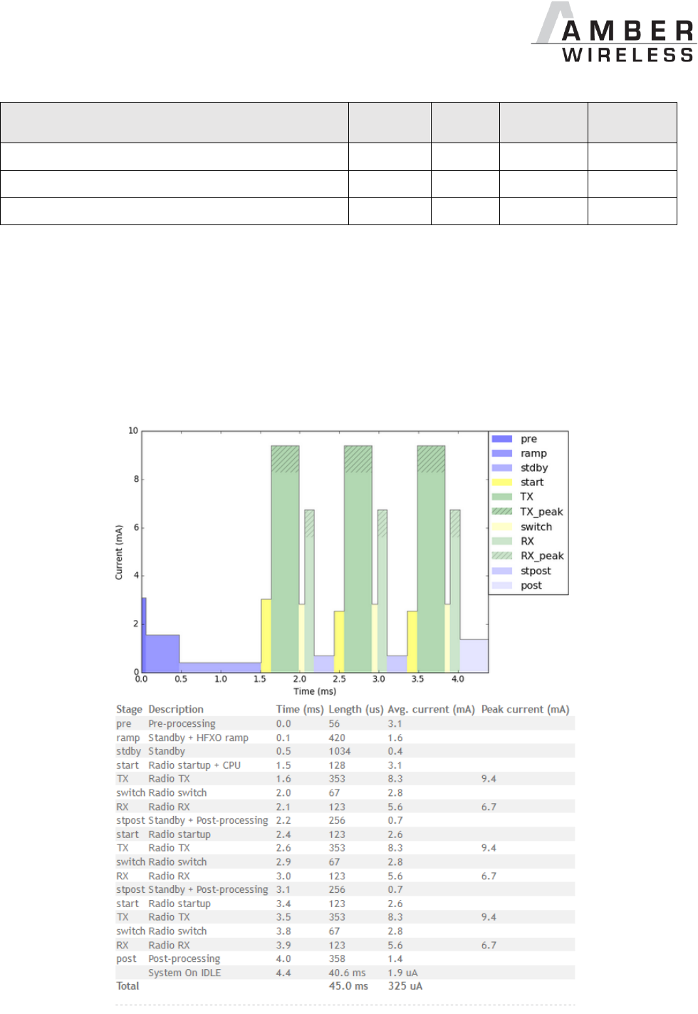
2.2.2 Typical current consumption
Besides the static TX, RX, IDLE and Sleep current the average current is of interest. Here an
example for a typical behaviour of a peripheral device in advertising mode (see Figure 1 and
Figure 2). Currents and state durations are dependent on the configuration (User Settings) of
the module.
In this state the module transmits the advertising packets on the 3 advertising channels.
Figure 1 Current consumption calculation in advertising mode with 40ms advertising interval
AMB2621_MA_2_4 Page 10 of 128 Date: 03/2017
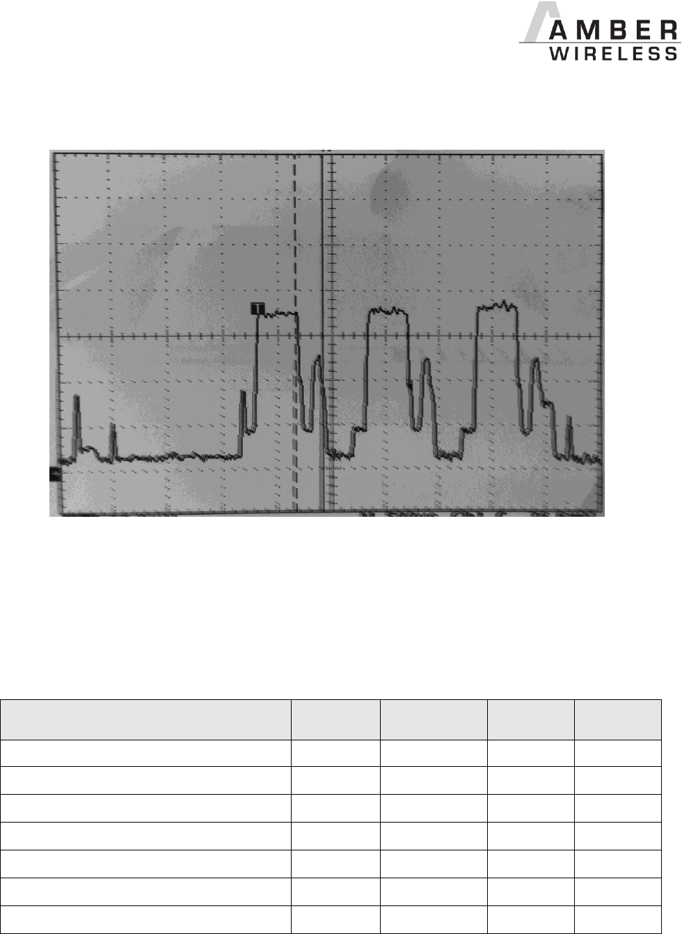
Figure 2 Transient current consumption in advertising mode with 40ms advertising interval,
excerpt of 5ms
2.3 Radio parameters (nRF52 data sheet)
50 Ohm tethered.
Description
min
typ.
max.
unit
Output power
-40
+4
+6
dBm
Input sensitivity (<= 37 bytes, BER=1E-3)
-96*, -92**
dBm
RSSI accuracy valid range (± 2dB)
-90
-20
dBm
Enable TX or RX Delay
140
µs
Enable TX or RX Delay (fast mode)
40
µs
Disable TX Delay
6
µs
Disable RX Delay
0
µs
* nRF52832 Rev.1, QFN package
** nRF52832 Rev.1, with build code CIAA-B00, CSP package, in DC/DC Mode

AMB2621_MA_2_4 Page 11 of 128 Date: 03/2017
Output power RF_TXPower = 4
min
typ.
max.
unit
AMB2621-1
+4
dBm
AMB2621
-2
dBm
2.4 Pin characteristics (nRF52 data sheet)
Description
min.
typ.
max.
unit
Input high voltage
0.7 * VCC
VCC
V
Input low Voltage
VSS
0.3 * VCC
V
Current at VSS+0.4 V, output set low, standard
drive, VDD ≥1.7
1
2
4
mA
Current at VSS+0.4 V, output set low, high drive,
VDD >= 2.7 V
6
10
15
mA
Current at VSS+0.4 V, output set low, high drive,
VDD >= 1.7 V
3
mA
Current at VDD-0.4 V, output set high, standard
drive, VCC ≥1.7
1
2
4
mA
Current at VDD-0.4 V, output set high, high
drive, VDD >= 2.7 V
6
9
14
mA
Current at VDD-0.4 V, output set high, high
drive, VDD >= 1.7 V
3
mA
Internal Pull-up resistance
13
kΩ
Internal Pull-down resistance
13
kΩ
3 Dimensions and weight
Dimensions
8 x 11 x 1.8 mm
Mass
<1 g
AMB2621_MA_2_4 Page 12 of 128 Date: 03/2017
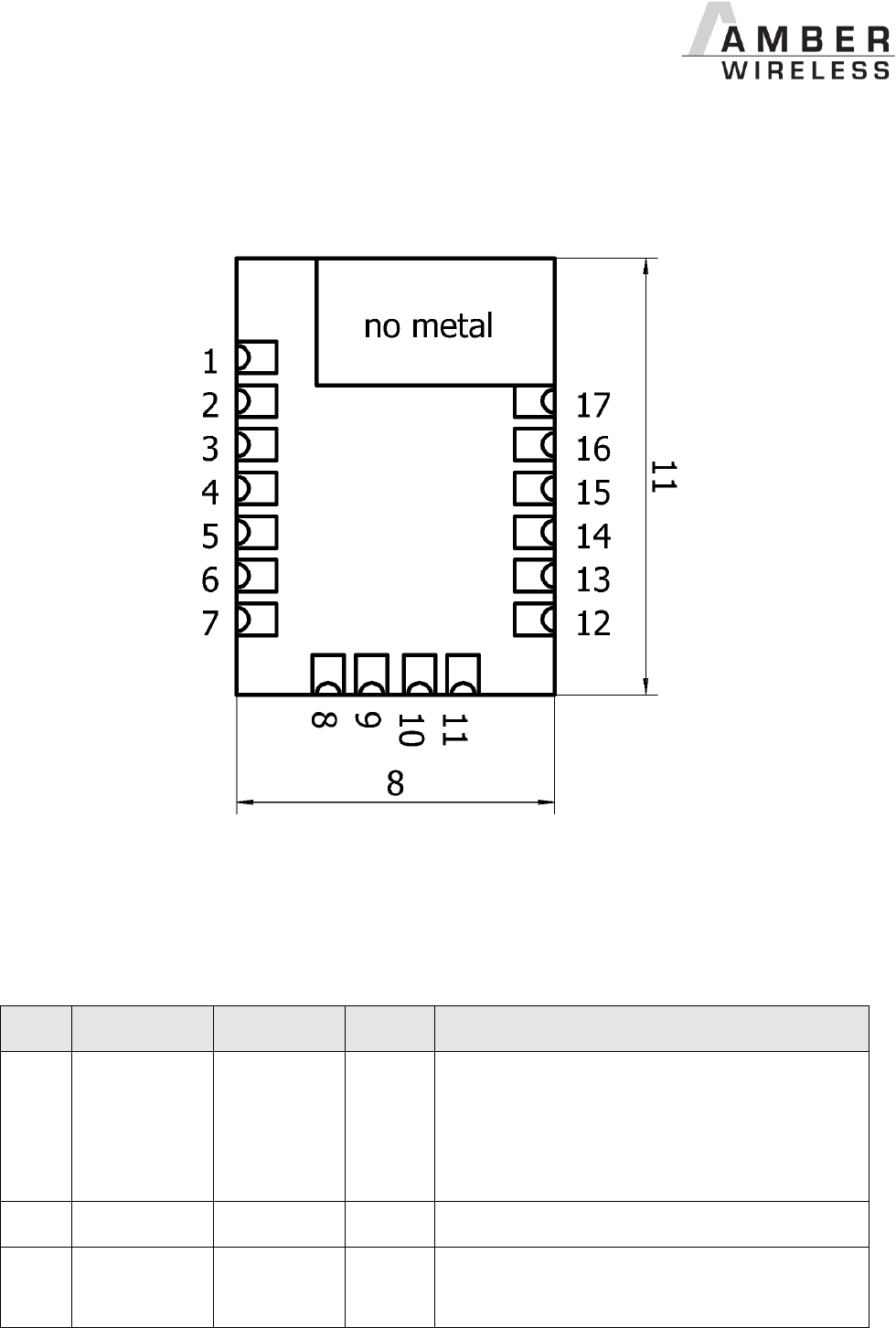
4 Pinout
Figure 3 Pinout
The following Pinout represents the AMB2621 module pads and the corresponding µC pins as
well as the function of the pad in the AMB2621 firmware. For customer specific firmware the
function of a pad may vary.
Pad
µC Pin
Designation
I/O
Description
1
RF
RF
Antenna connection.
Only applicable for module variant with
external Antenna (e.g. ABMB2621-1).
Do not connect in case of modules with
internal PCB antenna (e.g. ABMB2621).
2
GND
Supply
Ground
3
SWDCLK
Input
Serial wire clock. (SWD Interface)
Uses internal pulldown resistor.

AMB2621_MA_2_4 Page 13 of 128 Date: 03/2017
Pad
µC Pin
Designation
I/O
Description
4
SWDIO
Input
Serial wire input/output. (SWD Interface)
Do not connect if not needed.
5
P0.21
RESET
Input
Reset pin. A low signal resets the module.
Uses internal pullup resistor.1
6
P0.05/AIN3
BOOT
Input
Boot pin. A low signal during and short after
reset starts the module in OTA bootloader
mode.
Uses internal pullup resistor.1
Do not connect if not needed.
7
VDD
Supply
Supply voltage
8
P0.10/NFC2
OPERATION
MODE
Input
Operation mode pin with internal pulldown
resistor1 during start-up.
Low level or open: Normal Mode.
High level: Peripheral only Mode.
Do not connect if not needed.
9
P0.09/NFC1
RESERVED
I/O
Do not connect.
10
P0.00/XL1
LED_1
Output
Indicates the module state (active high).
Do not connect if not needed.
11
P0.01/XL2
LED_2
Output
Indicates the module state (active high).
Do not connect if not needed.
12
P0.02/AIN0
UART TX
Output
UART(Transmission)
13
P0.03/AIN1
UART RX
Input
UART (Reception)
Uses internal pullup resistor.1
14
P0.04/AIN2
RESERVED
I/O
Do not connect.
15
P0.28/AIN4
RESERVED
I/O
Do not connect.
16
P0.29/AIN5
Wake-up
Input
Wake-up will allow leaving the system-off
mode or re-enabling the UART.
Uses internal pullup resistor.1
Do not connect if not needed.
1
Internal pullup or pulldowns are configured at startup by the firmware installed in the SoC. The
pullup on the Reset pin cannot be disabled by firmware.

AMB2621_MA_2_4 Page 14 of 128 Date: 03/2017
Pad
µC Pin
Designation
I/O
Description
17
GND
Supply
Ground
Table 1 Pinout

AMB2621_MA_2_4 Page 15 of 128 Date: 03/2017
5 Start-up and minimal configuration
5.1 Minimal configuration
In factory state the modules are immediately ready for operation; the following pins are required
in the minimal configuration:
VDD, GND, UART TX, UART RX, RESET
If the module has to be connected to a PC, a converter (TTL to RS-232 or TTL to USB) has to
be used. See chapter 4 for details on all pins.
Please refer to the AMB2621-EV schemes for a reference design.
Implementing the fail-save firmware update method using the SWD interface is
recommended. Without having the SWD interface available a fail-save firmware update
on a customer PCB cannot be guaranteed, see next chapter.
The logic level of the module is based on 3V. A 5V logic level must not be connected
directly to the module.
5.2 Recommended configuration
We recommend to also have the following pins accessible in order to support a fail-safe
firmware update:
SWDIO, SWDCLK, BOOT
A standard socket on the customer’s PCB for connecting a Flash adapter can be useful for
debugging purposes (e.g. a JTAG 2*10 Pin header with 2.54mm pin-to-pin distance).
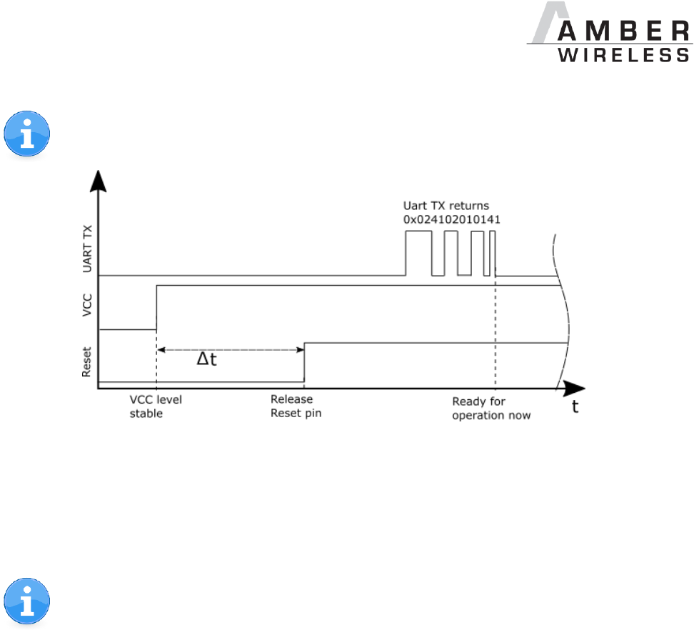
5.3 Power-up
After powering the module the Reset pin shall be hold for another Δt of 1ms after the VCC is
stable to ensure a safe start-up.
The module will send “CMD_GETSTATE_CNF” to indicate “ready for operation” after the Reset
pin was released.
AMB2621_MA_2_4 Page 16 of 128 Date: 03/2017
Applying a reset (e.g. a host temporarily pulling the Reset pin down for at least 1ms
and releasing it again) after the VCC is stable will also be sufficient.
5.4 Connecting to the AMB2621 via serial interface
To control the module the UART interface of the AMB2621 may be used. The default data rate
is 115200 Baud and the data format is 8 data bits, no parity and 1 stop bit ("8n1").
Please note that every command sent to the module correctly is confirmed by the
module.
If no confirmation is returned, the previously sent command was not understood.
Therefore a timeout and retry algorithm has to be implemented by the host.
AMB2621_MA_2_4 Page 17 of 128 Date: 03/2017
5.5 Quick start: Connection setup and first data transmission
This section describes how to quick start the data transmission between two AMB2621.
The goal is to setup a connection between module A and module B, transmit some data and
close the connection again by the following steps.
In this section, all packet data from or to the modules is given in hexadecimal notation.
For quick testing a pair of AMB2621-EV is recommended.
To reproduce the following sequence, note that, the FS_BTMAC of every module is
different, thus it has to be replaced it in the commands below. Also the XOR checksum
(last byte) has to be adjusted, when adapting any command.
The command structure and checksum calculation is described in chapter 8.
Note that the module goes to ACTION_SLEEP mode if no connection is setup after
RF_AdvertisingTimeout seconds. The module will indicate this using a
CMD_SLEEP_CNF. Also the UART is disabled in ACTION_SLEEP mode.
The default value is 0s which means that it’ll run forever
1. Power-up the modules and make their UARTs accessible by the host(s). After the
power-up following sequence is sent from the module:
Info
Module A
Module B
◄ Response CMD_GETSTATE_CNF
The module A started in ACTION_IDLE
mode.
02 41 02 00 01 01
41
◄ Response CMD_GETSTATE_CNF
The module B started in ACTION_IDLE
mode.
02 41 02 00 01 01
41
2. Request the FS_BTMAC of both modules.
Info
Module A
Module B
► Request CMD_GET_REQ
with settings index 4
02 10 01 00 04 17
◄ Response CMD_GET_CNF
FS_BTMAC of module A is
0x55 0x00 0x00 0xDA 0x18 0x00
02 50 07 00 00 55
00 00 DA 18 00 C2
► Request CMD_GET_REQ
with settings index 4
02 10 01 00 04 17
◄ Response CMD_GET_CNF
FS_BTMAC of module B is
0x11 0x00 0x00 0xDA 0x18 0x00
02 50 07 00 00 11
00 00 DA 18 00 86

AMB2621_MA_2_4 Page 18 of 128 Date: 03/2017
3. Connect Module A to Module B.
Note: this example is taken from an older firmware, so in the newer firmware with the
optional BT 4.2 feature “LE Packet Length Extension“ you may see other values than
0x13 for max supported payload length per packet in the opened channel (e.g. 0x80 =
128 byte max payload per packet).
Info
Module A
Module B
► Request CMD_CONNECT_REQ
with FS_BTMAC of module B
02 06 06 00 11 00
00 DA 18 00 D1
◄ Response CMD_CONNECT_CNF
Request understood, try to connect now
02 46 01 00 00 45
◄ Indication CMD_CONNECT_IND
Physical connection established
successfully to module with FS_BTMAC
0x11 0x00 0x00 0xDA 0x18 0x00
02 86 07 00 00 11
00 00 DA 18 00 50
◄ Indication CMD_CONNECT_IND
Physical connection established
successfully to module with FS_BTMAC
0x55 0x00 0x00 0xDA 0x18 0x00
02 86 07 00 00 55
00 00 DA 18 00 14
◄ Indication CMD_CHANNELOPEN_RSP
Channel opened successfully to module
with FS_BTMAC 0x11 0x00 0x00 0xDA
0x18 0x00 and maximum payload size of
0x13 (19 Bytes) per packet
02 C6 07 00 00 11
00 00 DA 18 00 13
C3
◄ Indication CMD_CHANNELOPEN_RSP
Channel opened successfully to module
with FS_BTMAC 0x55 0x00 0x00 0xDA
0x18 0x00 and maximum payload size of
0x13 (19 Bytes) per packet
02 C6 07 00 00 55
00 00 DA 18 00 13
87
4. Once the connection is active data can be sent in each direction. Let’s send a string
“ABCD” from Module B to module A. Note: The RSSI values will most probably be
different in your tests.
Info
Module A
Module B
► Request CMD_DATA_REQ
Send “ABCD” to module A
02 04 04 00 41 42
43 44 06
◄ Response CMD_DATA_CNF
Request received, send data now
02 44 01 00 00 47
◄ Indication CMD_DATA_IND
Received string “ABCD” from FS_BTMAC
0x11 0x00 0x00 0xDA 0x18 0x00 with
RSSI of 0xCA (-54dBm)
02 84 0B 00 11 00
00 DA 18 00 CA 41
42 43 44 90
◄ Response CMD_TXCOMPLETE_RSP
Data transmitted successfully
02 C4 01 00 00 C7

AMB2621_MA_2_4 Page 19 of 128 Date: 03/2017
5. Reply with “EFGH” to module B.
Info
Module A
Module B
► Request CMD_DATA_REQ
Send “EFGH” to module B
02 04 04 00 45 46
47 48 0E
◄ Response CMD_DATA_CNF
Request received, send data now
02 44 01 00 00 47
◄ Indication CMD_DATA_IND
Received string “EFGH” from FS_BTMAC
0x55 0x00 0x00 0xDA 0x18 0x00 with
RSSI of 0xC1 (-63dBm)
02 84 0B 00 55 00
00 DA 18 00 C1 45
46 47 48 D7
◄ Response CMD_TXCOMPLETE_RSP
Data transmitted successfully
02 C4 01 00 00 C7
6. Now Module A closes the connection, so both modules will get a disconnect indication.
Info
Module A
Module B
► Request CMD_DISCONNECT_REQ
Disconnect
02 07 00 00 05
◄ Response CMD_DISCONNECT_CNF
Request received, disconnect now
02 47 01 00 00 44
◄ Indication CMD_DISCONNECT_IND
Connection closed
02 87 01 00 16 92
◄ Indication CMD_DISCONNECT_IND
Connection closed
02 87 01 00 13 97

AMB2621_MA_2_4 Page 20 of 128 Date: 03/2017
6 State overview
The AMB2621 module acts as a slave and can be fully controlled by an external host that
implements the command interface. The configuration as well as the operation of the module
can be managed by predefined commands that are sent as telegrams over the UART interface
of the module.
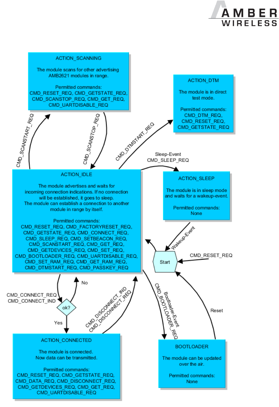
The AMB2621 can operate in different states. Depending on the active state several commands
of the command interface (see chapter 8) are permitted to modify the state, configure the
module or transmit data over the RF-interface. An overview of the different states and the
corresponding allowed commands can be found in Figure 4 on page 21.
When the AMB2621 is powered up, it starts in ACTION_IDLE state. In this state the module
advertises (BLE role “peripheral”), such that other devices in range (BLE role “central” or
“observer”) can detect it and connect to it. If no connection was setup after
RF_AdvertisingTimeout seconds, the module goes to ACTION_SLEEP state which will stop
advertising.
The ACTION_IDLE state also allows to switch to ACTION_SCANNING state, where the module
stops advertising and scans for other advertising modules in range (BLE role “central”).
When leaving the ACTION_SCANNING state with the corresponding command, the module is in
ACTION_IDLE state and starts advertising again.
The ACTION_CONNECTED state can be entered either by getting a connection request from
another module (BLE role “peripheral”) or by setting up a connection itself (BLE role “central”).
In this case it stops advertising and data can be transmitted and received to/from the connected
module. This state remains active as long as the module does not disconnect itself (e.g. due to
a timeout), no disconnection request from the connected device is received.
When disconnecting, the module goes to ACTION_IDLE state und starts advertising again.
AMB2621_MA_2_4 Page 21 of 128 Date: 03/2017
Figure 4 States of the AMB2621

AMB2621_MA_2_4 Page 22 of 128 Date: 03/2017
6.1 State indication using the LED pins
The pins LED_1 and LED_2 of the AMB2621 can be used to determine the module state. The
states described in Figure 4 result in the following pin behaviour. The pins on the AMB2621 are
active high.
State
LED_1
LED_2
ACTION_IDLE
Blinking
On for 200ms
Off for 2800ms
Off
ACTION_SCANNING
Blinking
On for 250ms
Off for 750ms
Off
ACTION_CONNECTED
On
Off
On (as soon as the channel
was opened successfully, see
CMD_CHANNELOPEN_RSP)
ACTION_SLEEP
Off
Off
ACTION_DTM
Off
Off
BOOTLOADER
Waiting for connection
On
Off
BOOTLOADER
Connected, firmware update
running
Off
On
Table 2 LED behaviour of the AMB2621
6.2 Reset behaviour
After resetting the module a CMD_GETSTATE_CNF is sent to the serial interface as soon as the
module is ready for operation. In default case the sent message (in hex notation) is 02 41 02 00
01 01 41 which indicates that the module is in ACTION_IDLE mode after having started-up
successfully.
6.3 Sleep mode
Especially for battery-powered devices the ACTION_SLEEP mode (system-off mode) supports
very low power consumption (<1µA). It can be entered by sending the command
CMD_SLEEP_REQ to the module. If allowed (due to the current operating state) the module will
then send a CMD_SLEEP_CNF and then enter the ACTION_SLEEP mode.

AMB2621_MA_2_4 Page 23 of 128 Date: 03/2017
In ACTION_SLEEP mode the UART is disabled, so the module will not receive or transmit any
data. To prevent leakage current, the host shall not pull the UART_RX to LOW level (as the
module has an internal pull-up resistor enabled on this pin).
To leave the ACTION_SLEEP mode and enter ACTION_IDLE state again, the module has to be
woken up by applying a low signal to the Wake-up pin for at least 5ms before releasing the
signal back to high. The module then restarts completely, so that all volatile settings are set to
default. A CMD_GETSTATE_CNF will be send when the module is ready for operation.
Note that the Wake-up pin has a second function. If the module is not in ACTION_SLEEP
mode and the UART was disabled using the CMD_UARTDISABLE_IND, the UART can be
re-enabled by applying a low signal for at least 5ms and releasing it to high again. In this
case the module answers with a CMD_UARTENABLE_IND.
6.4 Identification of an AMB2621 device on the air
The AMB2621 can be identified on the RF-interface by its FS_BTMAC. This FS_BTMAC is a
Bluetooth-conform MAC address, which is part of the data package sent during advertising in
ACTION_IDLE mode. A FS_BTMAC has the size of 6 byte.
In ACTION_SCANNING state a module listens to the data packets of all advertising modules in
range and stores their FS_BTMAC to an internal data base. With help of a FS_BTMAC a
connection to the corresponding device can then be established using the CMD_CONNECT_REQ
command.
To simplify the identification of AMB2621 devices on the RF-interface a short user-defined
name (see RF_DeviceName) can be given to the module, which is also part of the advertising
packet.
The FS_BTMAC consists of the Amber wireless company ID 0x0018DA followed by the
FS_SerialNumber of the module.
6.5 Connection based data transmission, with or without security
In the BLE standard the transmission of data typically is connection based. A connection
between two devices can be secured (with or without key exchange) or unsecured (default
setting). In any case, each data packet transmitted is acknowledged on the link layer, such that
it is resent as long as a packet is lost. The following lines describe how to run the connection
setup and data transmission using the AMB2621.
If module A is supposed to setup a connection with module B, module A can use the command
CMD_CONNECT_REQ including the FS_BTMAC of module B. If the FS_BTMAC of module B is
unknown, a scan can be run before by module A to discover all available modules in range (see
chapter 6.4).
After sending the command CMD_CONNECT_REQ, the module answers with a
CMD_CONNECT_CNF to signal that the request has been understood and the module now tries to
establish the connection.

AMB2621_MA_2_4 Page 24 of 128 Date: 03/2017
If module B cannot be found on the air within a timeout, module A outputs a
CMD_CONNECT_IND with “failed” as status. Otherwise, as soon as the physical connection has
been set up successfully, module A and B print a CMD_CONNECT_IND with the status of the
successful connection and LED_1 turns on.
Next some security and authentication messages will follow, like CMD_SECURITY_IND, if
security is enabled.
After the physical connection has been setup successfully the modules exchange their services.
As soon as this has finished successfully a CMD_CHANNELOPEN_RSP is given out to the UART
indicating that the connection is ready for data transmission. Furthermore LED_2 turns on.
Now data can be transmitted in both directions using the command CMD_DATA_REQ. It is
confirmed by a CMD_DATA_CNF (data will be processed) and a CMD_TXCOMPLETE_RSP (data
transmitted successfully).
Each time data has been received a CMD_DATA_IND will be outputted containing the
transmitted data.
As soon as one module closes the connection using a CMD_DISCONNECT_REQ, both modules
will inform their host by a CMD_DISCONNECT_IND message that the connection is no longer
open.
If one module is no longer within range the CMD_DISCONNECT_IND message is triggered by a
timeout.
For an example on setting up an unsecured connection see chapter 5.5. See also the advanced
user guide to get detailed information about the connection setup with foreign devices.
6.5.1 Further information for a secure connection setup
The RF_SecFlags parameter of the module determines the security mode. If a certain
security mode of an AMB2621 peripheral device is set, its security level has to be met by the
connecting central device to be able to exchange data. If the security level of the peripheral
device is not met during connection setup, the peripheral requests for a higher security level. As
soon as the defined security level is not met by the central device, no access to the peripheral’s
profiles will be granted.
When connecting from an AMB2621 to an AMB2621, you shall not use different
security modes.
In this case, if security is needed, we recommend to use the LTK method. It allows a
quick setup of a secured connection.
To get further information about the secured connection setup, when using a foreign
device (i.e. mobile phone with a custom APP), please refer to the “advanced user
guide”.

AMB2621_MA_2_4 Page 25 of 128 Date: 03/2017
6.5.1.1 Just works mode
In case of the “Just works” mode, each time a connection is established, a new random key is
exchanged in advance to be used for data encryption. Since no authentication will be
performed, also devices without input and output capabilities (like keyboard or display) are able
to connect.
6.5.1.1.1 Example: Secured connection with LE Legacy security method “Just Works”
1. Power-up the modules and make their UARTs accessible by the host(s). After the
power-up following sequence is sent from the module:
Info
Module A
Module B
◄ Response CMD_GETSTATE_CNF
The module A started in ACTION_IDLE
mode.
02 41 02 00 01 01
41
◄ Response CMD_GETSTATE_CNF
The module B started in ACTION_IDLE
mode.
02 41 02 00 01 01
41
2. Request the FS_BTMAC of both modules.
Info
Module A
Module B
► Request CMD_GET_REQ
with settings index 4
02 10 01 00 04 17
◄ Response CMD_GET_CNF
FS_BTMAC of module A is
0x55 0x00 0x00 0xDA 0x18 0x00
02 50 07 00 00 55
00 00 DA 18 00 C2
► Request CMD_GET_REQ
with settings index 4
02 10 01 00 04 17
◄ Response CMD_GET_CNF
FS_BTMAC of module B is
0x11 0x00 0x00 0xDA 0x18 0x00
02 50 07 00 00 11
00 00 DA 18 00 86

AMB2621_MA_2_4 Page 26 of 128 Date: 03/2017
3. Configure the parameter RF_SecFlags to use “Just Works” pairing method for BT
security
Info
Module A
Module B
►Perform CMD_SET_REQ
with settings index 12 and value 0x02 on
Module A
02 11 02 00 0C 02
1F
◄ Response CMD_SET_CNF
(Module will restart to adopt the new
value)
02 51 01 00 00 52
◄ Response CMD_GETSTATE_CNF
02 41 02 00 01 01
41
►Perform CMD_SET_REQ
with settings index 12 and value 0x02 on
Module B
02 11 02 00 0C 02
1F
◄ Response CMD_SET_CNF
(Module will restart to adopt the new
value)
02 51 01 00 00 52
◄ Response CMD_GETSTATE_CNF
02 41 02 00 01 01
41

AMB2621_MA_2_4 Page 27 of 128 Date: 03/2017
4. Connect Module A to Module B.
Note: this example is taken from an older firmware, so in the newer firmware with the
optional BT 4.2 feature “LE Packet Length Extension“ you may see other values than
0x13 for max supported payload length per packet in the opened channel (e.g. 0x80 =
128 byte max payload per packet).
Info
Module A
Module B
► Request CMD_CONNECT_REQ
with FS_BTMAC of module B
02 06 06 00 11 00
00 DA 18 00 D1
◄ Response CMD_CONNECT_CNF
Request understood, try to connect now
02 46 01 00 00 45
◄ Indication CMD_CONNECT_IND
Physical connection established
successfully to module with FS_BTMAC
0x11 0x00 0x00 0xDA 0x18 0x00
02 86 07 00 00 11
00 00 DA 18 00 50
◄ Indication CMD_CONNECT_IND
Physical connection established
successfully to module with FS_BTMAC
0x55 0x00 0x00 0xDA 0x18 0x00
02 86 07 00 00 55
00 00 DA 18 00 14
◄ Indication CMD_SECURITY_IND,
security mode = 1, security level = 2
(encrypted link, no MITM protection), with
FS_BTMAC 0x11 0x00 0x00 0xDA 0x18
0x00
02 88 07 00 12 11
00 00 DA 18 00 4C
◄ Indication CMD_SECURITY_IND,
security mode = 1, security level = 2
(encrypted link, no MITM protection), with
FS_BTMAC 0x55 0x00 0x00 0xDA 0x18
0x00
02 88 07 00 12 55
00 00 DA 18 00 08
◄ Indication CMD_CHANNELOPEN_RSP
Channel opened successfully to module
with FS_BTMAC 0x11 0x00 0x00 0xDA
0x18 0x00 and maximum payload size of
0x13 (19 Bytes) per packet
02 C6 07 00 00 11
00 00 DA 18 00 13
C3
◄ Indication CMD_CHANNELOPEN_RSP
Channel opened successfully to module
with FS_BTMAC 0x55 0x00 0x00 0xDA
0x18 0x00 and maximum payload size of
0x13 (19 Bytes) per packet
02 C6 07 00 00 55
00 00 DA 18 00 13
87

AMB2621_MA_2_4 Page 28 of 128 Date: 03/2017
5. Now Module A closes the connection, so both modules will get a disconnect indication.
Info
Module A
Module B
► Request CMD_DISCONNECT_REQ
Disconnect
02 07 00 00 05
◄ Response CMD_DISCONNECT_CNF
Request received, disconnect now
02 47 01 00 00 44
◄ Indication CMD_DISCONNECT_IND
Connection closed
02 87 01 00 16 92
◄ Indication CMD_DISCONNECT_IND
Connection closed
02 87 01 00 13 97
6. You may want to perform a CMD_FACTORYRESET_REQ to restore default settings.
6.5.1.2 LTK mode
In case of the “LTK” mode, a fixed long term key (LTK) is used for encrypting the data. This key
is not exchanged by the RF-interface and has to correlate on both sides of the connection. If the
keys do not match, the connection will be rejected.
1. If the AMB2621 sets up a connection to another device,
then the long term key stored in the parameter RF_PeerLTK is used. During the
connection setup, it has to correlate with the key of the peer device.
It can be modified by the CMD_SET_REQ, which writes its values into flash memory, or by
the CMD_SET_RAM_REQ, which stores its value in volatile RAM.
2. If the AMB2621 requested to connect by another device,
then the long term key stored in the parameter RF_OwnLTK is used. During the
connection setup, it has to correlate with the key of the peer device.
It can be modified by the CMD_SET_REQ, which writes its values into flash memory.
3. Consequently, if the AMB2621 connects to another AMB2621,
then the RF_PeerLTK of the connecting device must correlate with the RF_OwnLTK of
the connected device.
When consecutively connecting to several devices using the “LTK” mode, we
recommend to use the CMD_SET_RAM_REQ command to update the RF_PeerLTK to
the corresponding key. This saves flash cycles and thus increases the durability of the
module.
6.5.1.2.1 Example: Secured connection with security method “LTK”
1. Power-up the modules and make their UARTs accessible by the host(s). After the
power-up following sequence is sent from the module:

AMB2621_MA_2_4 Page 29 of 128 Date: 03/2017
Info
Module A
Module B
◄ Response CMD_GETSTATE_CNF
The module A started in ACTION_IDLE
mode.
02 41 02 00 01 01
41
◄ Response CMD_GETSTATE_CNF
The module B started in ACTION_IDLE
mode.
02 41 02 00 01 01
41
2. Request the FS_BTMAC of both modules.
Info
Module A
Module B
► Request CMD_GET_REQ
with settings index 4
02 10 01 00 04 17
◄ Response CMD_GET_CNF
FS_BTMAC of module A is
0x55 0x00 0x00 0xDA 0x18 0x00
02 50 07 00 00 55
00 00 DA 18 00 C2
► Request CMD_GET_REQ
with settings index 4
02 10 01 00 04 17
◄ Response CMD_GET_CNF
FS_BTMAC of module B is
0x11 0x00 0x00 0xDA 0x18 0x00
02 50 07 00 00 11
00 00 DA 18 00 86
3. Configure the parameter RF_SecFlags to use “LTK” method for BT security
Info
Module A
Module B
►Perform CMD_SET_REQ
with settings index 12 and value 0x01 on
Module A
02 11 02 00 0C 01
1C
◄ Response CMD_SET_CNF
(Module will restart to adopt the new
value)
02 51 01 00 00 52
◄ Response CMD_GETSTATE_CNF
02 41 02 00 01 01
41
►Perform CMD_SET_REQ
with settings index 12 and value 0x01 on
Module B
02 11 02 00 0C 01
1C
◄ Response CMD_SET_CNF
(Module will restart to adopt the new
value)
02 51 01 00 00 52
◄ Response CMD_GETSTATE_CNF
02 41 02 00 01 01
41

AMB2621_MA_2_4 Page 30 of 128 Date: 03/2017
4. Connect Module A to Module B.
Note: this example is taken from an older firmware, so in the newer firmware with the
optional BT 4.2 feature “LE Packet Length Extension“ you may see other values than
0x13 for max supported payload length per packet in the opened channel (e.g. 0x80 =
128 byte max payload per packet).
Note further: The RF_PeerLTK of the module A coincides with the RF_OwnLTK of the
module B. This is needed to setup successfully the connection.
Info
Module A
Module B
► Request CMD_CONNECT_REQ
with FS_BTMAC of module B
02 06 06 00 11 00
00 DA 18 00 D1
◄ Response CMD_CONNECT_CNF
Request understood, try to connect now
02 46 01 00 00 45
◄ Indication CMD_CONNECT_IND
Physical connection established
successfully to module with FS_BTMAC
0x11 0x00 0x00 0xDA 0x18 0x00
02 86 07 00 00 11
00 00 DA 18 00 50
◄ Indication CMD_CONNECT_IND
Physical connection established
successfully to module with FS_BTMAC
0x55 0x00 0x00 0xDA 0x18 0x00
02 86 07 00 00 55
00 00 DA 18 00 14
◄ Indication CMD_SECURITY_IND,
security mode = 1, security level = 3
(encrypted link, MITM protection), with
FS_BTMAC 0x11 0x00 0x00 0xDA 0x18
0x00
02 88 07 00 13 11
00 00 DA 18 00 4D
◄ Indication CMD_SECURITY_IND,
security mode = 1, security level = 3
(encrypted link, MITM protection), with
FS_BTMAC 0x55 0x00 0x00 0xDA 0x18
0x00
02 88 07 00 13 55
00 00 DA 18 00 09
◄ Indication CMD_CHANNELOPEN_RSP
Channel opened successfully to module
with FS_BTMAC 0x11 0x00 0x00 0xDA
0x18 0x00 and maximum payload size of
0x13 (19 Bytes) per packet
02 C6 07 00 00 11
00 00 DA 18 00 13
C3
◄ Indication CMD_CHANNELOPEN_RSP
Channel opened successfully to module
with FS_BTMAC 0x55 0x00 0x00 0xDA
0x18 0x00 and maximum payload size of
0x13 (19 Bytes) per packet
02 C6 07 00 00 55
00 00 DA 18 00 13
87

AMB2621_MA_2_4 Page 31 of 128 Date: 03/2017
5. Now Module A closes the connection, so both modules will get a disconnect indication.
Info
Module A
Module B
► Request CMD_DISCONNECT_REQ
Disconnect
02 07 00 00 05
◄ Response CMD_DISCONNECT_CNF
Request received, disconnect now
02 47 01 00 00 44
◄ Indication CMD_DISCONNECT_IND
Connection closed
02 87 01 00 16 92
◄ Indication CMD_DISCONNECT_IND
Connection closed
02 87 01 00 13 97
6. You may want to perform a CMD_FACTORYRESET_REQ to restore default settings.
6.5.1.3 Static PassKey mode
In case of the “StaticPassKey” mode, a pass key has to be entered at the central side that has
to match the pass key of the peripheral. Here the AMB2621 uses a static pass key in the
peripheral role that is stored in the parameter RF_StaticPassKey. When using this method,
the central device requests its host to enter a pass key (see CMD_PASSKEY_IND). In this case
the pass key of the peripheral has to be entered on central side using the CMD_PASSKEY_REQ
command. If the entered pass key is correct, the channel will be opened. Otherwise, the
connection will be rejected.
6.5.1.3.1 Example: Secured connection with security method “StaticPassKey”
7. Power-up the modules and make their UARTs accessible by the host(s). After the
power-up following sequence is sent from the module:
Info
Module A
Module B
◄ Response CMD_GETSTATE_CNF
The module A started in ACTION_IDLE
mode.
02 41 02 00 01 01
41
◄ Response CMD_GETSTATE_CNF
The module B started in ACTION_IDLE
mode.
02 41 02 00 01 01
41

AMB2621_MA_2_4 Page 32 of 128 Date: 03/2017
8. Request the FS_BTMAC of both modules.
Info
Module A
Module B
► Request CMD_GET_REQ
with settings index 4
02 10 01 00 04 17
◄ Response CMD_GET_CNF
FS_BTMAC of module A is
0x55 0x00 0x00 0xDA 0x18 0x00
02 50 07 00 00 55
00 00 DA 18 00 C2
► Request CMD_GET_REQ
with settings index 4
02 10 01 00 04 17
◄ Response CMD_GET_CNF
FS_BTMAC of module B is
0x11 0x00 0x00 0xDA 0x18 0x00
02 50 07 00 00 11
00 00 DA 18 00 86
9. Configure the parameter RF_SecFlags to use “StaticPassKey” method for BT security
Info
Module A
Module B
►Perform CMD_SET_REQ
with settings index 12 and value 0x03 on
Module A
02 11 02 00 0C 03
1E
◄ Response CMD_SET_CNF
(Module will restart to adopt the new
value)
02 51 01 00 00 52
◄ Response CMD_GETSTATE_CNF
02 41 02 00 01 01
41
►Perform CMD_SET_REQ
with settings index 12 and value 0x03 on
Module B
02 11 02 00 0C 03
1E
◄ Response CMD_SET_CNF
(Module will restart to adopt the new
value)
02 51 01 00 00 52
◄ Response CMD_GETSTATE_CNF
02 41 02 00 01 01
41

AMB2621_MA_2_4 Page 33 of 128 Date: 03/2017
10. Connect Module A to Module B.
Note: this example is taken from an older firmware, so in the newer firmware with the
optional BT 4.2 feature “LE Packet Length Extension“ you may see other values than
0x13 for max supported payload length per packet in the opened channel (e.g. 0x80 =
128 byte max payload per packet).
Note further: Here the RF_StaticPassKey of the module B is “123123”.
Info
Module A
Module B
► Request CMD_CONNECT_REQ
with FS_BTMAC of module B
02 06 06 00 11 00
00 DA 18 00 D1
◄ Response CMD_CONNECT_CNF
Request understood, try to connect now
02 46 01 00 00 45
◄ Indication CMD_CONNECT_IND
Physical connection established
successfully to module with FS_BTMAC
0x11 0x00 0x00 0xDA 0x18 0x00
02 86 07 00 00 11
00 00 DA 18 00 50
◄ Indication CMD_CONNECT_IND
Physical connection established
successfully to module with FS_BTMAC
0x55 0x00 0x00 0xDA 0x18 0x00
02 86 07 00 00 55
00 00 DA 18 00 14
◄ Indication CMD_PASSKEY_IND to ask
for the pass key
02 8D 07 00 00 11
00 00 DA 18 00 5B
►Answer with the CMD_PASSKEY_REQ
and the pass key “123123”
02 0D 06 00 31 32
33 31 32 33 09
◄ Response CMD_PASSKEY_CNF
Pass key ok
02 4D 01 00 00 4E
◄ Indication CMD_SECURITY_IND,
security mode = 1, security level = 3
(encrypted link, MITM protection), with
FS_BTMAC 0x11 0x00 0x00 0xDA 0x18
0x00
02 88 07 00 13 11
00 00 DA 18 00 4D
◄ Indication CMD_SECURITY_IND,
security mode = 1, security level = 3
(encrypted link, MITM protection), with
FS_BTMAC 0x55 0x00 0x00 0xDA 0x18
0x00
02 88 07 00 13 55
00 00 DA 18 00 09
◄ Indication CMD_CHANNELOPEN_RSP
Channel opened successfully to module
with FS_BTMAC 0x11 0x00 0x00 0xDA
0x18 0x00 and maximum payload size of
0x13 (19 Bytes) per packet
02 C6 07 00 00 11
00 00 DA 18 00 13
C3
◄ Indication CMD_CHANNELOPEN_RSP
Channel opened successfully to module
with FS_BTMAC 0x55 0x00 0x00 0xDA
0x18 0x00 and maximum payload size of
0x13 (19 Bytes) per packet
02 C6 07 00 00 55
00 00 DA 18 00 13
87

AMB2621_MA_2_4 Page 34 of 128 Date: 03/2017
11. Now Module A closes the connection, so both modules will get a disconnect indication.
Info
Module A
Module B
► Request CMD_DISCONNECT_REQ
Disconnect
02 07 00 00 05
◄ Response CMD_DISCONNECT_CNF
Request received, disconnect now
02 47 01 00 00 44
◄ Indication CMD_DISCONNECT_IND
Connection closed
02 87 01 00 16 92
◄ Indication CMD_DISCONNECT_IND
Connection closed
02 87 01 00 13 97
12. You may want to perform a CMD_FACTORYRESET_REQ to restore default settings.
6.6 Unidirectional connectionless data transmission using Beacons
Besides the connection-based type of data transmission described in section 6.5 there exists a
second method which uses so called Beacons. In this case, a limited amount of user data can
be placed in the BLE scan response packet which is broadcasted frequently without
acknowledgement and without security.
If an AMB2621 is supposed to broadcast some data, the command CMD_SETBEACON_REQ can
be used to place user data in the scan response packet.
If a second AMB2621, which has its Beacon-function (see RF_BeaconFlags) enabled, is in the
operating state ACTION_SCANNING, then the scan response packet is requested as soon as an
advertising packet from the first module has been detected. Filtering the beacon messages can
be enabled or disabled using RF_BeaconFlags.
After the reception of the scan response packet the included user data is interpreted and given
out to the UART using a CMD_BEACON_IND message.
To set the module into ACTION_SCANNING mode the command CMD_SCANSTART_REQ has to
be used. Enable the Beacon-function before by setting the corresponding bit in the
RF_BeaconFlags parameter.
This method is very suitable for sensor networks, which frequently send their data to
data collectors. Especially when using a slow RF_ScanTiming mode, data can be
transmitted in a more energy efficient way.
Please check the settings RF_AdvertisingTimeout and the advertising interval in
RF_ScanTiming to configure the frequency and interval of transmissions which will
have an influence on the current consumption of the module.
6.6.1 Example: Unfiltered Beacons
Module A shall be the sender of beacons, module B the receiver.

AMB2621_MA_2_4 Page 35 of 128 Date: 03/2017
Info
Module A
Module B
◄ Reset both modules using reset pin,
CMD_GETSTATE_CNF
02 41 02 00 01 01 41
02 41 02 00 01 01 41
► Configure RF_BeaconFlags
using CMD_SET_REQ to
„beacon rx enabled, no filter“
02 11 02 00 0E 01 1E
◄ CMD_SET_CNF from module B
02 51 01 00 00 52
◄ Module B resetted such that the
change in the user setting takes effect
(CMD_GETSTATE_CNF)
02 41 02 00 01 01 41
► Activate scanning on module B
02 09 00 00 0B
◄ Response CMD_SCANSTART_CNF
02 49 01 00 00 4A
► CMD_SETBEACON_REQ,
content “Hallo”
02 0C 05 00 48 61 6C
6C 6F 4D
◄ CMD_SETBEACON_CNF
02 4C 01 00 00 4F
◄ receiving multiple
CMD_BEACON_IND
02 8C 0C 00 02 00 00 DA 18
00 B5 48 61 6C 6C 6F B1 02
8C 0C 00 02 00 00 DA 18 00
B1 48 61 6C 6C 6F B5
⁞
► Deactivate scanning on module B,
CMD_SCANSTOP_REQ
02 0A 00 00 08
◄ Response CMD_SCANSTOP_CNF
02 4A 01 00 00 49
► Reset module A (disable sending
beacons),
CMD_RESET_REQ
02 00 00 00 02
◄ Response CMD_RESET_CNF
02 40 01 00 00 43
◄ Response CMD_GETSTATE_CNF
02 41 02 00 01 01 41
6.7 Energy-efficient distance estimation solutions
The AMB2621 advertising packet contains the TX power value of the transmitting device. This
value in combination with the RSSI value of the received advertising packet can be used to
estimate the distance between the modules. Using a suitable triangulation algorithm and
multiple receivers or transmitters, a position can be approximated.

AMB2621_MA_2_4 Page 36 of 128 Date: 03/2017
The advertising packets can be received by performing a passive scan that will not request the
scan response. Thus only one frame, instead of three frames, is transmitted per advertising
interval.
Besides the FS_BTMAC of the sending module, the RSSI value and the TX power is outputted in
format of a CMD_RSSI_IND message via UART when an advertising packet of another
AMB2621 has been received.
To enable this function, the corresponding bit in the RF_BeaconFlags has to be set.
6.8 Configure the module for low power consumption
Depending on the application environment of the AMB2621, the goal is to find the optimal trade-
off between the module’s performance and its power consumption. Therefore the main settings
and operation modes that affect the current consumption are listed below:
CMD_SLEEP_REQ: This command puts the module into ACTION_SLEEP mode, where it
consumes the lowest current (<1µA). In this case both the UART and the BLE interface
are shut down.
CMD_UARTDISABLE_REQ: This command disables the UART interface. It is enabled
again as soon as the module is reset/woken or when the module outputs a message
e.g. when a connection request has been received or the Wake-up pin of the module
was used.
RF_TXPower: This setting can be used to configure the output power of the module.
Reducing the output power saves energy.
RF_ScanTiming and RF_ScanFactor: These settings define the timing behaviour of
the module, when advertising or scanning. The less often the module sends advertising
packets or scans, the less current is consumed.
RF_ConnectionTiming: This setting defines the timing behaviour of the module
during connection setup and an established connection. The less often the connected
modules communicate with each other, the less current is consumed.
The on-board nRF52 SoC is running in Debug mode. This will not occur if the pins are
connected as described in this manual.
For optimum energy efficiency a user and application specific firmware may be
required.
6.9 Start the direct test mode (DTM)
The direct test mode (DTM) enables the test functions described in Bluetooth Specification
Version 4.0, Vol. 6, Part F. The purpose of DTM is to test the operation of the radio at the
physical level, such as:
transmission power and receiver sensitivity
frequency offset and drift

AMB2621_MA_2_4 Page 37 of 128 Date: 03/2017
modulation characteristics
packet error rate
intermodulation performance
Conformance tests on the nRF52 with the DTM application as the device under test (DUT) are
carried out by dedicated test equipment.
To get access to the test functions the CMD_DTMSTART_REQ shall be used first. This command
restarts the module in direct test mode. A CMD_GETSTATE_CNF message (0x02 0x41 0x02
0x00 0x10 0x05 0x54) confirms that the DTM has been started successfully.
Now the CMD_DTM_REQ can be used to start and stop the test functions. After a test has been
started, it has to be stopped before a next test can be run.
6.9.1 Example: Transmission test on channel 0 with bit pattern 0x0F
The goal of this example is to show how the DTM, and in specific the transmission/reception
test, can be run. Here fore we need to connect two modules, start the transmission test on one
module and start the reception test on the second module.
In this section, all packet data from or to the modules is given in hexadecimal notation.
All steps are described in the following:
1. First restart the modules in DTM mode.
Info
Module A
Module B
► Request CMD_DTMSTART_REQ
to enable the DTM on module A
02 1D 00 00 1F
◄ Response CMD_DTMSTART_CNF
Request understood, try to start DTM now
02 5D 01 00 00 5E
◄ Indication CMD_GETSTATE_CNF
Restarted module with DTM enabled
02 41 02 00 10 05
54
► Request CMD_DTMSTART_REQ
to enable the DTM on module B
02 1D 00 00 1F
◄ Response CMD_DTMSTART_CNF
Request understood, try to start DTM now
02 5D 01 00 00 5E
◄ Indication CMD_GETSTATE_CNF
Restarted module with DTM enabled
02 41 02 00 10 05
54

AMB2621_MA_2_4 Page 38 of 128 Date: 03/2017
2. Now both modules are ready for the DTM. Start the transmission test first.
Info
Module A
Module B
► Request CMD_DTM_REQ
to start the transmission test on module A
with channel 0 and bit pattern 16 times
0x0F
02 1E 04 00 02 00
10 01 0B
◄ Response CMD_DTM_CNF
Started test successfully
02 5E 03 00 00 00
00 5F
3. Start the reception test.
Info
Module A
Module B
► Request CMD_DTM_REQ
to start the reception test on module B with
channel 0 bit pattern 0x0F
02 1E 04 00 01 00
00 01 18
◄ Response CMD_DTM_CNF
Started test successfully
02 5E 03 00 00 00
00 5F
4. Stop both tests again.
Info
Module A
Module B
► Request CMD_DTM_REQ
to stop the transmission test
02 1E 04 00 03 00
00 01 1A
◄ Response CMD_DTM_CNF
Stopped test successfully
02 5E 03 00 00 80
00 DF
► Request CMD_DTM_REQ
to stop the reception test
02 1E 04 00 03 00
00 01 1A
◄ Response CMD_DTM_CNF
Stopped test successfully, received
0x14FE (5374dec) packets
02 5E 03 00 00 94
FE 35
During the time the reception and transmission tests were running 5374 data packets have
been received by module B, which were transmitted by module A.

AMB2621_MA_2_4 Page 39 of 128 Date: 03/2017
7 Timing behaviour
7.1 Reset and sleep
After power-up, resetting the module or waking the module from sleep a CMD_GETSTATE_CNF
is sent to the serial interface as soon as the module is ready for operation.
Description
typ.
unit
Ready after reset/sleep
4
ms
7.2 BLE timing parameters
The timing parameters for sending advertising packets or scanning are determined by the user
settings RF_ScanTiming, RF_ScanFactor and RF_AdvertisingTimeout. Using these
settings, the advertising interval, the advertising timeout, the scan interval and the scan window
can be configured.
Furthermore, the user setting RF_ConnectionTiming allows to configure the timing
parameters used during connection setup and connection retention, as well as the connection
interval and the connection supervision timeout.
7.3 Connection establishment
The time needed to establish a connection sums up as the time needed to detect the selected
peripheral on air and the time needed for connection parameter negotiation and service
discovery.
1. Peripheral detection
To establish a connection, the initiating device (central) waits for an advertising packet,
which was sent by the peripheral to which it wants to connect to. As soon as such an
advertising packet has been received, the central sends a connection request to the
chosen peripheral.
The time needed to receive this advertising packet strongly depends on the advertising
interval of the peripheral as well as on the scan interval and scan window of the central
(see RF_ScanTiming).
2. Connection parameter negotiation
After the connection request has been sent the central and peripheral negotiate the
timing and security parameters of the connection. To finish this procedure and discover
the services of the peripheral several messages have to be sent, whereby only one is
sent per connection interval (see RF_ConnectionTiming).

AMB2621_MA_2_4 Page 40 of 128 Date: 03/2017
Connection type
Estimated number of
exchanged messages
Negotiation time for a
connection interval of 50ms
Unsecured connection
9-11
450-550ms
Secured connection
using predefined long
term keys (LTK)
16-18
800-900ms
Secured connection
using the pairing method
22-24
1100-1200ms
Knowing the connection interval and the number of messages that will be sent, the time
necessary to setup a connection can be estimated by multiplying the number of
messages with the connection interval.
7.4 Connection based data transmission
After setting up a connection, data can be transmitted using the CMD_DATA_REQ. It buffers the
data in the module and sends it with the next connection interval event. As soon as the data has
been transmitted successfully a CMD_TXCOMPLETE_RSP is returned by the UART. The time
needed for this coincides with the connection interval that was negotiated during connection
setup. The RF_ConnectionTiming parameter defines the minimum and maximum
connection interval which is supported by the module.
AMB2621_MA_2_4 Page 41 of 128 Date: 03/2017
8 The command interface
The AMB2621 acts as a slave and can be fully controlled by an external host. The configuration
as well as the operation of the module can be managed by predefined commands that are sent
as telegrams over the UART interface of the module.
The commands of the command interface can be divided into 3 groups:
Requests: The host requests the module to trigger any action, e.g. in case of the request
CMD_RESET_REQ the host asks the AMB2621 to perform a reset.
Confirmations: On each request the module answers with a confirm message to give a
feedback on the requested operation status. In case of a CMD_RESET_REQ, the module
answers with a CMD_RESET_CNF to tell the host whether the reset will be performed or
not.
Indications and Responses: The module indicates spontaneously when a special event
has occurred. The CMD_CONNECT_IND for example indicates that a connection has
been established.
All commands have to be of the format as described in Table 3.
If the command contains parameter(s) with a size of more than 1 byte in the Data section these
parameters are to be transmitted LSB first, unless notified otherwise in the respective
command.
Start signal
Command
Length
Data
Checksum
1 Byte
1 Byte
2 Byte, LSB first
Length Byte
1 Byte
Table 3 Telegram format in the command mode
Start signal: 0x02
Command: One of the predefined commands
Length: Specifies the data length in the following and is limited to 120 bytes (unless
stated otherwise in the command description) in order to prevent buffer overflow.
Length is a 16Bit field with LSB first.
Data: Variable data or parameters corresponding to the value of the “Data length” field.
Checksum: Byte wise XOR combination of the preceding fields including the start signal, i.e.
0x02 ^ command ^ Length ^ data byte 0...

AMB2621_MA_2_4 Page 42 of 128 Date: 03/2017
If the transmission of the UART command has not finished within the packet
transmission duration (depending on the currently selected UART Baud rate) + 5ms
after having received the start signal, the module will discard the received bytes and
wait for a new command.
This means that the delay between 2 successive bytes in a frame must be kept as low
as possible.
Please note that the different commands are only valid in specific module states (see
Figure 4).
If a command is not permitted in the current state, the command confirmation returns
“Operation not permitted” as a response.
AMB2621_MA_2_4 Page 43 of 128 Date: 03/2017
8.1 Scan for other modules in range
8.1.1 CMD_SCANSTART_REQ
This command starts the scan operation to find other AMB2621 in range. All found devices that
fit the AMB2621 specification (i.e. devices that support AMBER SPP service UUID) are saved in
an internal data base. Before outputting the data base content using the command
CMD_GETDEVICES_REQ, the scan has to be stopped using CMD_SCANSTOP_REQ.
Format:
Start signal
Command
Length
CS
0x02
0x09
0x00 0x00
0x0B
Response (CMD_SCANSTART_CNF):
Start signal
Command | 0x40
Length
Status
CS
0x02
0x49
0x01 0x00
1 Byte
1 Byte
Status:
0x00: Request received, will start scan now
0x01: Operation failed
0xFF: Operation not permitted
8.1.2 CMD_SCANSTOP_REQ
This command stops the scan operation that was started using CMD_SCANSTART_REQ. It stores
the detected AMB2621 FS_BTMAC addresses in an internal database, which can be outputted
using the CMD_GETDEVICES_REQ.
Format:
Start signal
Command
Length
CS
0x02
0x0A
0x00 0x00
0x08
Response (CMD_SCANSTOP_CNF):
Start signal
Command | 0x40
Length
Status
CS
0x02
0x4A
0x01 0x00
1 Byte
1 Byte
Status:
AMB2621_MA_2_4 Page 44 of 128 Date: 03/2017
0x00: Request received, will stop scan now
0x01: Operation failed
0xFF: Operation not permitted
8.1.3 CMD_GETDEVICES_REQ
This command returns the information about the devices found during the last scan operation.
#Devices determines the number of devices that have been detected. The corresponding
information will be outputted one after the other in the field behind #Devices in the
CMD_GETDEVICES_CNF response. The RSSI and TXPower values are transmitted in the two’s
complement notation.
Format:
Start signal
Command
Length
CS
0x02
0x0B
0x00 0x00
0x09
Response (CMD_GETDEVICES_CNF):
Start
signal
Command |
0x40
Length
Status
#Devices
Payload
CS
0x02
0x4B
2 Byte
1 Byte
1 Byte
Length – 2 Byte
1 Byte
The Payload sequentially lists the data of the detected #Devices devices. It consists of
#Devices times the following telegram (see example below).
BTMAC
RSSI
TXPower
Device name
length
Device name
6 Bytes
1 Byte
1 Byte
1 Byte
Device name length bytes
Status:
0x00: Request received
0x01: Operation failed
0xFF: Operation not permitted
AMB2621_MA_2_4 Page 45 of 128 Date: 03/2017
If there are too many devices found to be outputted, the response of the
CMD_GETDEVICES_REQ is split into several CMD_GETDEVICES_CNF messages.
If RSSI = 0x80, there is no value available.
If TXPower = 0x80, there is no value available.
If Device name length = 0, then there is no device name available.
8.1.3.1 Example 1
Request for the FS_BTMAC of the devices found during the last scan.
Start signal
Command
Length
CS
0x02
0x0B
0x00 0x00
0x09
Response:
Start
signal
Command
| 0x40
Length
Status
#Devices
Payload
CS
0x02
0x4B
0x1E 00
0x00
0x02
0x11 0x00 0x00 0xDA 0x18 0x00
0xE2
0x04
0x05
0x4D 0x4F 0x44 0x20 0x31
0x55 0x00 0x00 0xDA 0x18 0x00
0xE5
0x00
0x05
0x4D 0x4F 0x44 0x20 0x32
0x11
During the last scan two devices have been detected:
Device 1 with FS_BTMAC 0x11 0x00 0x00 0xDA 0x18 0x00, RSSI value of 0xE2 (-30
dBm), TXPower of 0x04 (=+4 dBm) and device name of length 5 with the value of
0x4D4F442031 (“MOD 1”).
Device 2 with FS_BTMAC 0x55 0x00 0x00 0xDA 0x18 0x00 and RSSI value of 0xE5 (-27
dBm), TXPower of 0x00 (0 dBm) and device name 0x4D4F442032 (“MOD 2”) of length
5.

AMB2621_MA_2_4 Page 46 of 128 Date: 03/2017
8.1.4 CMD_RSSI_IND
This telegram indicates the reception of an advertising packet sent by another AMB2621
module. It can be used to realize a position sensing application. This data can only be received,
when the module is in ACTION_SCANNING mode (passive scan is sufficient) and the
corresponding bit in the RF_BeaconFlags is set.
Besides the FS_BTMAC, the RSSI value of the advertising packet and the transmission power of
the sending device are outputted. Both, the RSSI value and the TX power, are in two’s
complement notation.
The accuracy is ±2dB when inside the RSSI range of -90 to -20 dB.
The value of the parameter TX Power is read from the content of the received advertise packet.
Start signal
Command
Length
BTMAC
RSSI
TX Power
CS
0x02
0x8B
2 Bytes
6 Byte
1 Byte
1 Byte
1 Byte
AMB2621_MA_2_4 Page 47 of 128 Date: 03/2017
8.2 Setup connections
8.2.1 CMD_CONNECT_REQ
This command tries to setup a connection to the AMB2621 which is identified by the FS_BTMAC
used in the command. After the module prints a CMD_CONNECT_CNF to confirm that the request
was received, the indication message CMD_CONNECT_IND follows which determines whether
the connection request was accepted by the other device.
In case of enabled security features (see the setting RF_SecFlags) a CMD_SECURITY_IND is
outputted in addition.
As soon as the connection setup has been completed and all services have been discovered
successfully a CMD_CHANNELOPEN_RSP is printed by the UART. Now data may be sent using
the CMD_DATA_REQ.
Format:
Start signal
Command
Length
BTMAC
CS
0x02
0x06
0x06 0x00
6 Byte
1 Byte
Response (CMD_CONNECT_CNF):
Start signal
Command | 0x40
Length
Status
CS
0x02
0x46
0x01 0x00
1 Byte
1 Byte
Status:
0x00: Request received, try to connect to the device with the FS_BTMAC
0x01: Operation failed
0xFF: Operation not permitted
8.2.2 CMD_CONNECT_IND
This telegram indicates the connection status and the FS_BTMAC of the connected device. This
indication message is the result of a connection request (CMD_CONNECT_REQ).
Start signal
Command
Length
Status
BTMAC
CS
0x02
0x86
0x07 0x00
1 Byte
6 Byte
1 Byte
Status:
0x00: Physical connection established successfully
0x01: Connection failed, e.g. due to a timeout (as defined by RF_ScanTiming)

AMB2621_MA_2_4 Page 48 of 128 Date: 03/2017
8.2.3 CMD_SECURITY_IND
This telegram indicates the security status and the FS_BTMAC of the connected device. This
indication message is the result of a connection request (CMD_CONNECT_REQ).
Start signal
Command
Length
Status
BTMAC
CS
0x02
0x88
0x07 0x00
1 Byte
6 Byte
1 Byte
Status:
0xXY: X security mode, Y security level
Security Mode 0 Level 0: No access permissions at all
Security Mode 1 Level 1: No security
Security Mode 1 Level 2: Encrypted link, no MITM protection
Security Mode 1 Level 3: MITM protected encrypted link
8.2.4 CMD_CHANNELOPEN_RSP
This command is printed on the UART as soon as connection setup and service discovery has
been completed successfully. Now data can be transmitted using the CMD_DATA_REQ. Next to
the FS_BTMAC of the connected device, the maximum payload size that is supported by the link
is part of this telegram.
This message is the result of a connection request (CMD_CONNECT_REQ).
Format:
Start
signal
Command
Length
Status
BTMAC
Max
payload
CS
0x02
0xC6
0x08 0x00
1 Byte
6 Byte
1 Byte
1 Byte
Status:
0x00: Success
8.2.5 CMD_DISCONNECT_REQ
This command shuts down the existing connection. Thereafter the module prints a
CMD_DISCONNECT_CNF to confirm that the request has been received, the indication message
CMD_DISCONNECT_IND follows which determines whether the disconnection operation has
been performed successfully or not.
Format:
AMB2621_MA_2_4 Page 49 of 128 Date: 03/2017
Start signal
Command
Length
CS
0x02
0x07
0x00 0x00
0x05
Response (CMD_DISCONNECT_CNF):
Start signal
Command | 0x40
Length
Status
CS
0x02
0x47
0x01 0x00
1 Byte
1 Byte
Status:
0x00: Request received, try to disconnect
0x01: Operation failed
0xFF: Operation not permitted
8.2.6 CMD_DISCONNECT_IND
This telegram indicates that the connection has shut down successfully. This indication
message is the result of a disconnection request (CMD_DISCONNECT_REQ).
Start signal
Command
Length
Reason
CS
0x02
0x87
0x01 0x00
1 Byte
1 Byte
Reason:
0x08: Connection timeout
0x13: User terminated connection
0x16: Host terminated connection
0x3B: Connection interval unacceptable
0x3D: Connection terminated due to MIC failure
(Not able to connect due to bad link quality,
or connection request ignored due to wrong key)
0x3E: Connection setup failed
8.2.7 CMD_PASSKEY_REQ
When receiving a CMD_PASSKEY_IND during connection setup, the peripheral requests for a
pass key to authenticate the connecting device.
To answer this request the CMD_PASSKEY_REQ message has to be sent to the AMB2621
central including the pass key of the peripheral.
The permissible characters of the pass key are ranging from 0x30 to 0x39 (both included) which
are ASCII numbers (0-9).

AMB2621_MA_2_4 Page 50 of 128 Date: 03/2017
Format:
Start signal
Command
Length
Pass key
CS
0x02
0x0D
0x06 0x00
6 Bytes pass key
1 Byte
Response (CMD_PASSKEY_CNF):
Start signal
Command | 0x40
Length
Status
CS
0x02
0x4D
0x01 0x00
1 Byte
1 Byte
Status:
0x00: Pass key accepted and pass key request answered
0x01: Operation failed, due to invalid pass key
0xFF: Operation not permitted
8.2.8 CMD_PASSKEY_IND
Depending on the security settings of the peripheral, a pass key has to be entered on the
central side to authenticate the central device. When such a pass key authentication request is
received on the central side this CMD_PASSKEY_IND message is send to the host. In this case,
the pass key has to be entered using the CMD_PASSKEY_REQ to successfully finish the
connection procedure.
Start signal
Command
Length
Status
BTMAC
CS
0x02
0x8D
0x07 0x00
1 Byte
6 Byte
1 Byte
Status:
0x00: Success
AMB2621_MA_2_4 Page 51 of 128 Date: 03/2017
8.3 Transmit and receive data
8.3.1 CMD_DATA_REQ
This command provides the simple data transfer between two connected modules.
Transmission takes place to the previously connected device(s). This command is suitable for
transmission for a point-to-point connection. The number of payload data bytes is negotiated
during the connection phase. It can be maximal 128 bytes, but at least 19 bytes.
When the data is processed by the module a CMD_DATA_CNF is outputted by the UART.
Additionally a CMD_TXCOMPLETE_RSP will follow as soon as the data has been sent.
The receiving AMB2621 will get a CMD_DATA_IND message containing the transmitted payload
data.
Format:
Start signal
Command
Length
Payload
CS
0x02
0x04
2 Bytes
Length Bytes
1 Byte
Response (CMD_DATA_CNF):
Start signal
Command | 0x40
Length
Status
CS
0x02
0x44
2 Bytes
Length Bytes
1 Byte
Status:
0x00: Request received, will send data now
0x01 + 0xXX: Operation failed + 0xXX maximum payload size (if it was exceeded)
0xFF: Operation not permitted
8.3.2 CMD_TXCOMPLETE_RSP
This command is outputted to the UART as soon as the data, which was requested by a
CMD_DATA_REQ has been transmitted successfully.
Format:
Start signal
Command
Length
Status
CS
0x02
0xC4
0x01 0x00
1 Byte
1 Byte
Status:
0x00: Data transmitted successfully
0x01: Data transmission failed
AMB2621_MA_2_4 Page 52 of 128 Date: 03/2017
8.3.3 CMD_DATA_IND
This telegram indicates the reception of data sent by the previously connected device. This
indication message is the result of a data request (CMD_DATA_REQ) sent to the associated
device within a connection.
The CMD_DATA_IND returns the FS_BTMAC of the sending device, the RSSI value of the
received data packet and the data received via the RF-interface which can be found in the
payload. The RSSI value is printed in two’s complement notation.
Start signal
Command
Length
BTMAC
RSSI
Payload
CS
0x02
0x84
2 Bytes
6 Bytes
1 Byte
Length -7 Byte
1 Byte
8.3.4 CMD_SETBEACON_REQ
This command is used to place user data in the scan response packet. The data is broadcasted
frequently without acknowledgement and security. No connection is needed for this mode of
operation.
It can be received by any scanning AMB2621 with Beacon-function enabled (see
RF_BeaconFlags). The receiving module will output a CMD_BEACON_IND indication message
containing the transmitted data. See chapter 6.5.1.2 for more information.
The number of payload data bytes is limited to 19.
Start signal
Command
Length
Payload
CS
0x02
0x0C
2 Bytes
Length bytes
1 Byte
Response (CMD_SETBEACON_CNF):
Start signal
Command | 0x40
Length
Status
CS
0x02
0x4C
0x01 0x00
1 Byte
1 Byte
Status:
0x00: Request received, will place data now
0x01: Operation failed
0xFF: Operation not permitted
8.3.5 CMD_BEACON_IND
This telegram indicates the reception of data bytes that have been transmitted in a beacon-
packet. This data can only be received, when the module is in ACTION_SCANNING mode and
the Beacon-function is enabled (see RF_BeaconFlags).
The data received via the RF-interface can be found in the payload of the CMD_BEACON_IND
telegram. Besides this, the FS_BTMAC of the sending device and the RSSI value of the data
packet are outputted as well. The RSSI value is outputted in two’s complement notation.

AMB2621_MA_2_4 Page 53 of 128 Date: 03/2017
Start signal
Command
Length
BTMAC
RSSI
Payload
CS
0x02
0x8C
2 Bytes
6 Bytes
1 Byte
Length -7 Byte
1 Byte

AMB2621_MA_2_4 Page 54 of 128 Date: 03/2017
8.4 Configuring the module and modifying the device settings
It is strongly recommended to have identical settings on all devices which have to open
a connection with each other or are to be used in Beacon mode.
The module’s parameters are stored in flash, but have a local copy in RAM. The flash
parameters can be modified by the CMD_SET_REQ, read by the CMD_GET_REQ and retain their
content even when resetting the module.
Some of the RAM parameters can be modified by the CMD_SET_RAM_REQ, read by the
CMD_GET_RAM_REQ and their content is replaced by the flash content when resetting the
module.
The flash memory has a limited count of write cycles. For periodic modifications try to
use the CMD_SET_RAM_REQ instead of CMD_SET_REQ as each CMD_SET_REQ
command will use one write cycle.
8.4.1 CMD_SET_REQ
This command enables direct manipulation of the parameters in the module’s settings in flash.
The respective parameters are accessed by means of the corresponding settings index which
can be found in Table 8.
Parameters of 2 or more bytes have to be transferred with the LSB first unless noted differently
in the corresponding description.
AMB2621_MA_2_4 Page 55 of 128 Date: 03/2017
The modified parameters only take effect after a restart of the module. This may be
done by a CMD_RESET_REQ if the module does not restart automatically.
The flash memory used to store these settings has a limited count of write cycles. Try
to avoid performing periodic CMD_SET_REQ as each command will use one write cycle.
Caution: The validity of the specified parameters is not verified. Incorrect values can
result in device malfunction!
To save the parameters in the flash memory of the module, the particular memory
segment must first be flushed entirely and then restored from RAM.
If a reset occurs during this procedure, the entire memory area may be corrupted
(e.g. due to supply voltage fluctuations).
Recommendation: First verify the configuration of the module with CMD_GET_REQ and
only then apply a CMD_SET_REQ if required to avoid unnecessary flash cycles.
Format:
Start signal
Command
Length
Settings index
Parameter
CS
0x02
0x11
2 Bytes
1 Byte
Length - 1 Byte
1 Byte
Response (CMD_SET_CNF):
Start signal
Command | 0x40
Length
Status
CS
0x02
0x51
0x01 0x00
1 Byte
1 Byte
Status:
0x00: Request received, settings set successfully
0x01: Operation failed due to invalid parameter
0x04: Serious error, when writing flash. Try to factory reset or reflash the device
0xFF: Operation not permitted
8.4.1.1 Example 1
Setting the advertising time RF_AdvertisingTimeout to 180 seconds.
AMB2621_MA_2_4 Page 56 of 128 Date: 03/2017
Start signal
Command
Length
Settings index
Parameter
CS
0x02
0x11
0x03 0x00
0x07
0xB4 0x00
0xA3
Response:
Start signal
Command | 0x40
Length
Status
CS
0x02
0x51
0x01 0x00
0x00
0x52
Setting was set successfully.
8.4.1.2 Example 2
Setting the local long term key RF_OwnLTK to 0x52 0x63 0x43 0x44 0x34 0x73 0x45.
Start
signal
Command
Length
Settings
index
Parameter
(Length – 1 Byte)
CS
0x02
0x11
0x08 0x00
0x05
0x52 0x63 0x43 0x44 0x34 0x73 0x45
0x2A
Response:
Start signal
Command | 0x40
Length
Status
CS
0x02
0x51
0x01 0x00
0x00
0x52
Long Term Key (LTK) was set successfully.
AMB2621_MA_2_4 Page 57 of 128 Date: 03/2017
8.4.2 CMD_GET_REQ
This command can be used to query individual setting parameters in flash. The respective
parameters are accessed by means of the corresponding settings index which can be found in
Table 8.
Parameters of 2 or more bytes have to be transferred with the LSB first unless noted differently
in the corresponding description.
Read access to the memory area outside the setting is blocked.
Format:
Start signal
Command
Length
Settings index
CS
0x02
0x10
0x01 0x00
1 Byte
1 Byte
Response (CMD_GETS_CNF):
Start signal
Command | 0x40
Length
Status
Parameter
CS
0x02
0x50
2 Bytes
1 Byte
Length -1 Byte
1 Byte
Status:
0x00: Request received, read out of setting successful
0x01: Operation failed
0xFF: Operation not permitted
8.4.2.1 Example 1
Request the current long term key RF_OwnLTK. The size of the key can be up to 16 byte:
Start signal
Command
Length
Settings index
CS
0x02
0x10
0x01 0x00
0x05
0x16
Response: The current RF_OwnLTK in flash is “AMB_DEFAULT_KEY” (0x41 0x4D 0x42
0x5F 0x44 0x45 0x46 0x41 0x55 0x4C 0x54 0x5F 0x4B 0x45 0x59).
Start
signal
Command |
0x40
Length
Status
Parameter
(Length -1 Byte)
CS
0x02
0x50
0x10 0x00
0x00
0x41 0x4D 0x42 0x5F 0x44 0x45 0x46
0x41 0x55 0x4C 0x54 0x5F 0x4B
0x45 0x59
0x10
AMB2621_MA_2_4 Page 58 of 128 Date: 03/2017
8.4.3 CMD_SET_RAM_REQ
This command enables direct manipulation of the parameters in the module’s settings in RAM.
The available parameters are accessed by means of the corresponding settings index which
can be found in Table 8.
Parameters of 2 or more bytes have to be transferred with the LSB first unless noted differently
in the corresponding description.
Caution: The validity of the specified parameters is not verified. Incorrect values can
result in device malfunction!
Format:
Start signal
Command
Length
Settings index
Parameter
CS
0x02
0x21
2 Bytes
1 Byte
Length - 1 Byte
1 Byte
Response (CMD_SET_CNF):
Start signal
Command | 0x40
Length
Status
CS
0x02
0x61
0x01 0x00
1 Byte
1 Byte
Status:
0x00: Request received, settings set successfully
0x01: Operation failed due to invalid parameter
0xFF: Operation not permitted
8.4.3.1 Example 1
Setting the RF_PeerLTK to 0x78 0x56 0x45 0x37 0x78 0x7A 0x41.
Start signal
Command
Length
Settings index
Parameter
CS
0x02
0x21
0x08 0x00
0x06
0x78 0x56
0x45 0x37
0x78 0x7A
0x41
0x32
Response:
Start signal
Command | 0x40
Length
Status
CS
0x02
0x61
0x01 0x00
0x00
0x62
Setting was set successfully.
AMB2621_MA_2_4 Page 59 of 128 Date: 03/2017
8.4.4 CMD_GET_RAM_REQ
This command can be used to query individual setting parameters in RAM. The respective
parameters are accessed by means of the corresponding settings index which can be found in
Table 8.
Parameters of 2 or more bytes have to be transferred with the LSB first unless noted differently
in the corresponding description.
Read access to the memory area outside the setting is blocked.
Format:
Start signal
Command
Length
Settings index
CS
0x02
0x20
0x01 0x00
1 Byte
1 Byte
Response (CMD_GETS_CNF):
Start signal
Command | 0x40
Length
Status
Parameter
CS
0x02
0x60
2 Bytes
1 Byte
Length -1 Byte
1 Byte
Status:
0x00: Request received, read out of setting successful
0x01: Operation failed
0xFF: Operation not permitted
8.4.4.1 Example 1
Request the RF_PeerLTK. The size of the key can be up to 16 byte:
Start signal
Command
Length
Settings index
CS
0x02
0x20
0x01 0x00
0x06
0x25
Response: The current key in RAM is 0x78 0x56 0x45 0x37 0x78 0x7A 0x41 .
Start
signal
Command |
0x40
Length
Status
Parameter
(Length -1 Byte)
CS
0x02
0x60
0x08 0x00
0x00
0x78 0x56 0x45 0x37 0x78 0x7A 0x41
0x75

AMB2621_MA_2_4 Page 60 of 128 Date: 03/2017
8.5 Manage the device state
8.5.1 CMD_GETSTATE_REQ
This command returns the current state of the module.
Please refer to chapter 6 for details on the states of the module.
Format:
Start signal
Command
Length
CS
0x02
0x01
0x00 0x00
0x03
Response (CMD_GETSTATE_CNF):
Start
signal
Command
| 0x40
Length
Module role
Module
action
More info
(optional field)
CS
0x02
0x41
2 Bytes
1 Byte
1 Byte
Length - 2
bytes
1 Byte
Module role:
0x00: No role
0x01: Peripheral
0x02: Central
0x10: Direct test mode (DTM)
Other: reserved
Module action:
0x00: No action
0x01: Idle (advertising)
0x02: Scanning
0x03: Connected (More info is the 6-bytes FS_BTMAC address of the connected device)
0x04: Sleep (system-off mode)
0x05: Direct test mode
8.5.1.1 Example 1
Get the current state of the module.

AMB2621_MA_2_4 Page 61 of 128 Date: 03/2017
Start signal
Command
Length
CS
0x02
0x01
0x00 0x00
0x03
Response:
Start
signal
Command
| 0x40
Length
Module role
Module
action
More info
(Length - 2 byte)
CS
0x02
0x41
0x08 0x00
0x02
0x03
0x11 0x00 0x00
0xDA 0x18 0x00
0x99
The module is connected to another module with FS_BTMAC 0x11 0x00 0x00 0xDA 0x18 0x00.
8.5.2 CMD_RESET_REQ
This command triggers a software reset of the module.
Format:
Start signal
Command
Length
CS
0x02
0x00
0x00 0x00
0x02
Response (CMD_RESET_CNF):
Start signal
Command | 0x40
Length
Status
CS
0x02
0x40
0x01 0x00
1 Byte
1 Byte
Status:
0x00: Request received, will perform reset now
0x01: Operation failed
0xFF: Operation not permitted
8.5.3 CMD_SLEEP_REQ
This command is used to start the system-off mode (ACTION_SLEEP). After entering this mode,
the module has to be woken up using the Wake-up pin (apply a low signal at this for at least
5ms and release it to high again) before any other action can be performed. The UART
interface as well as the BLE interface are shut down in this mode. For more details please see
also chapter 6.3.
AMB2621_MA_2_4 Page 62 of 128 Date: 03/2017
Format:
Start signal
Command
Length
CS
0x02
0x02
0x00 0x00
0x00
Response (CMD_SLEEP_CNF):
Start signal
Command | 0x40
Length
Status
CS
0x02
0x42
0x01 0x00
1 Byte
1 Byte
Status:
0x00: Request received, will go to sleep now
0x01: Operation failed
0xFF: Operation not permitted
Please note that the Wake-up pin has a second function. If the module is not in
ACTION_SLEEP mode and the UART was disabled using the
CMD_UARTDISABLE_REQ, the UART can be re-enabled by applying a low signal at this
for at least 5ms and releasing it again to high. In this case the module answers with a
CMD_UARTENABLE_IND.
8.5.4 CMD_SLEEP_IND
This indication is send by the module when the RF_AdvertisingTimeout has expired without a
connection to the module.
Indication (CMD_SLEEP_IND):
Start signal
Command | 0x80
Length
Status
CS
0x02
0x82
0x01 0x00
1 Byte
1 Byte
Status:
0x00: Advertising Timeout detected, will go to sleep now
8.5.5 CMD_FACTORYRESET_REQ
This command triggers a factory reset of the module. First the default User Settings are
restored, then the module is reset.
Format:
AMB2621_MA_2_4 Page 63 of 128 Date: 03/2017
Start signal
Command
Length
CS
0x02
0x1C
0x00 0x00
0x1E
Response (CMD_FACTORYRESET_CNF):
Start signal
Command | 0x40
Length
Status
CS
0x02
0x5C
0x01 0x00
1 Byte
1 Byte
Status:
0x00: Request received, will perform reset now
0x01: Operation failed
0xFF: Operation not permitted
To save the parameters in the flash memory of the module, the particular memory
segment must first be flushed entirely and then restored from RAM.
If a reset occurs during this procedure (e.g. due to supply voltage fluctuations), the
entire memory area may be destroyed.
During start-up of the device, the user settings memory is checked for consistency. In
case of inconsistency (e.g. the memory was erased) the device will perform a factory
reset.
8.5.6 CMD_UARTDISABLE_REQ
This command disables the UART of the module. It will be re-enabled when the module has to
send data to the host (e.g. data was received via RF or a state is indicated) or if the Wake-up
pin is used (hold at least 5ms low before releasing). In this case either the received data or a
CMD_UARTENABLE_IND is transmitted by the module. Afterwards the UART will stay active until
another CMD_UARTDISABLE_REQ or CMD_SLEEP_REQ or a timer triggered sleep event occurs.
Format:
Start signal
Command
Length
CS
0x02
0x1B
0x00 0x00
0x19
Response (CMD_UARTDISABLE_CNF):
Start signal
Command | 0x40
Length
Status
CS
0x02
0x5B
0x01 0x00
1 Byte
1 Byte
Status:
AMB2621_MA_2_4 Page 64 of 128 Date: 03/2017
0x00: Request received, will disable UART now
0x01: Operation failed
0xFF: Operation not permitted
We insistently recommend to disable the UART using this command only, if it is
foreseeable that there will be no UART communication for several seconds! Use cases
could be during advertising phase to wait for connecting BLE devices or when
broadcasting data via Beacons.
Disabling the UART peripheral of the module results in a reduction of current
consumption of about 1,15mA.
Please note that the Wake-up pin has a second function. If the module is in
ACTION_SLEEP mode, this pin wakes up the module by applying a low signal at this
for at least 5ms and releasing it again to high. In this case the module answers with a
CMD_GETSTATE_CNF.
8.5.7 CMD_UARTENABLE_IND
This indication is shown when the UART of the module is re-enabled (after performing a
CMD_UARTDISABLE_REQ followed by using the Wake-up pin). After receiving this message the
UART can be used for any operation again.
Indication:
Start signal
Command
Length
Status
CS
0x02
0x9B
0x01 0x00
1 Byte
1 Byte
Status:
0x00: UART has been re-enabled successfully
8.5.8 CMD_BOOTLOADER_REQ
This command resets the module and starts the OTA bootloader.
Use this command with caution. Please refer to chapter 10 on how to use the
bootloader for a firmware update.
Please note that you can only exit the bootloader mode by performing a hardware
reset using the respective pin.
AMB2621_MA_2_4 Page 65 of 128 Date: 03/2017
The bootloader mode will also be enabled if the firmware image is marked “invalid” or if
the BOOT pin logic level (set by the host) is set to start the bootloader during start-up
of the module.
Format:
Start signal
Command
Length
CS
0x02
0x1F
0x00 0x00
0x1D
Response (CMD_BOOTLOADER_CNF):
Start signal
Command | 0x40
Length
Status
CS
0x02
0x5F
0x01 0x00
1 Byte
1 Byte
Status:
0x00: Request received, will start bootloader now
0x01: Operation failed
0xFF: Operation not permitted
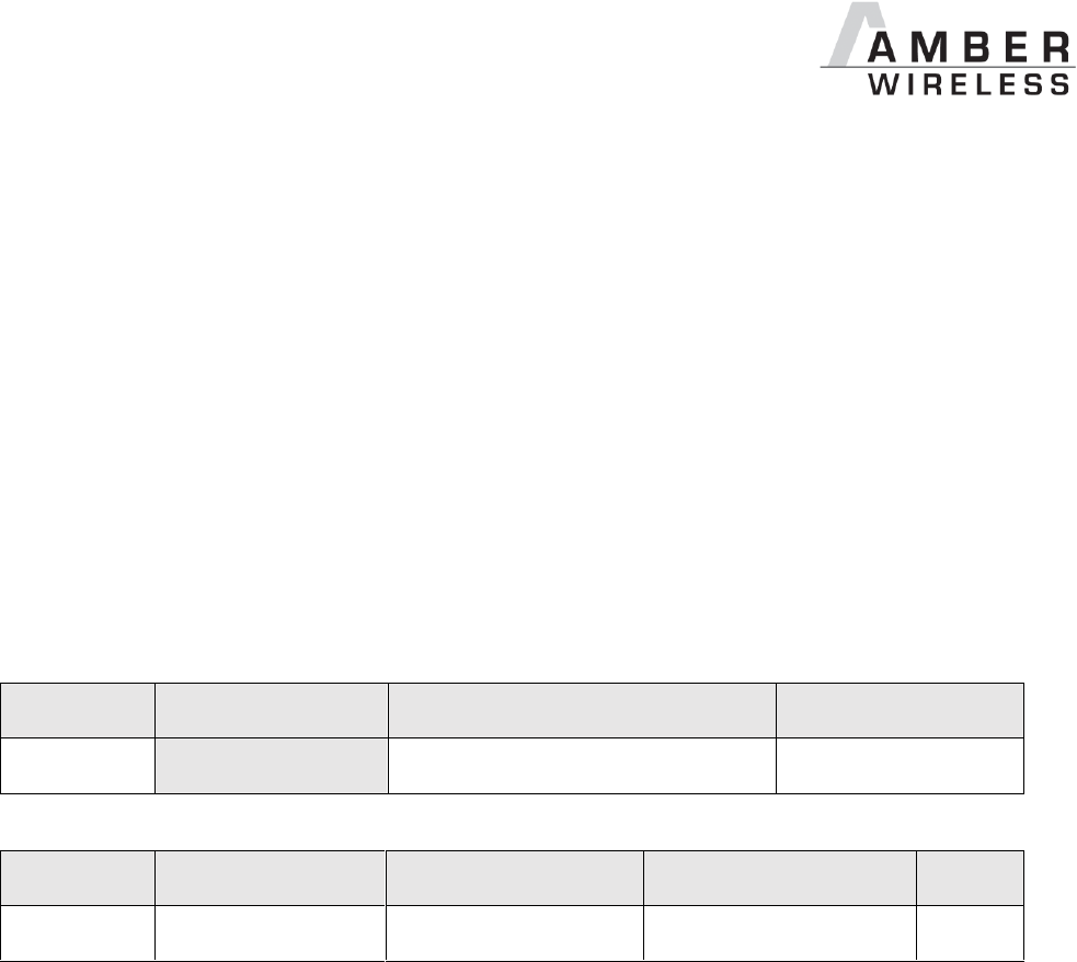
AMB2621_MA_2_4 Page 66 of 128 Date: 03/2017
8.6 Run the Bluetooth test modes
The test modes “DTM” as specified by the Bluetooth SIG are defined in the Bluetooth Core
specification v4.0 Volume 6.
8.6.1 CMD_DTMSTART_REQ
This command restarts the module in direct test mode (DTM). When starting in DTM mode, a
CMD_GETSTATE_CNF message (0x02 0x41 0x02 0x10 0x05 0x54) follows which indicates that
the test mode has been enabled successfully. Now the CMD_DTM_REQ can be used to start and
stop various test modes.
As soon as the module is reset, the DTM will be left again and normal operations can be
performed.
Performing a reset will leave the DTM and restart the module in the IDLE state.
Format:
Start signal
Command
Length
CS
0x02
0x1D
0x00 0x00
0x1F
Response (CMD_DTMSTART_CNF):
Start signal
Command | 0x40
Length
Status
CS
0x02
0x5D
0x01 0x00
1 Byte
1 Byte
Status:
0x00: Request received, will enable DTM now
0x01: Operation failed
0xFF: Operation not permitted
8.6.2 CMD_DTM_REQ
This command starts and stops various test modes. To be able to run these test modes, the
DTM has to be enabled first using the CMD_DTMSTART_REQ. After a test has been started, it
has to be stopped first before a next test can be run.
The default TXPower value is 0 dBm (0x00), the allowed range is from -40 up to +4 dBm in
steps of 4dB (see chapter 9.1.18).
The valid range for Channel (or Vendor option in case of Vendor Command = Carrier Test) is
0…39 (0x00 to 0x27).

AMB2621_MA_2_4 Page 67 of 128 Date: 03/2017
Format:
Start
signal
Command
Length
Command
code
Channel /
Vendor option
Length /
Vendor
command
Payload
CS
0x02
0x1E
0x04 0x00
1 Byte
1 Byte
1 Byte
1 Byte
1 Byte
Command code:
0x00: DTM reset (note: this command does not perform a module reset.
0x01: Start RX test
0x02: Start TX test
0x03: Stop last test
Payload:
0x00: Bit pattern PRBS9
0x01: Bit pattern 0x0F
0x02: Bit pattern 0x55
0x03: Vendor specific
Payload ≠ Vendor specific
(0x00, 0x01 or 0x02)
Payload = Vendor specific
(0x03)
Length / Vendor Command:
Length of the packet to send
Length / Vendor Command:
0x00: Carrier test
0x02: Set transmission power
Channel:
Frequency = (2402 + Channel * 2) MHz
to be used for RX/TX
Vendor option:
(dependant on used “Vendor command”)
Frequency = (2402 + [Vendor option] * 2) MHz
or
[Vendor option] := TXPower (in two’s complement
notation) in steps of 4dB
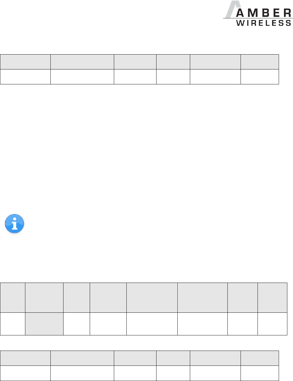
AMB2621_MA_2_4 Page 68 of 128 Date: 03/2017
Response (CMD_DTM_CNF):
Start signal
Command | 0x40
Length
Status
Result
CS
0x02
0x5E
2 Bytes
1 Byte
0-2 Byte
1 Byte
Status:
0x00: Request received
0x01: Operation failed
0x03: Busy
0xFF: Operation not permitted
Result:
0x0000: Test success
0x0001: Test error
0x8000 + n: Received n packets during RX test
See example in chapter 6.9.1.
8.6.2.1 Example: Transmission, 16 times 0x0F, channel 0
Start the transmission test on channel 0 (2402 MHz). The packets consist of 16 times 0x0F:
Start
signal
Command
Length
Command
code
Channel /
Vendor option
Length /
Vendor
command
Payload
CS
0x02
0x1E
0x04
0x00
0x02
0x00
0x10
0x01
0x0B
Response (CMD_DTM_CNF):
Start signal
Command | 0x40
Length
Status
Result
CS
0x02
0x5E
0x03 0x00
0x00
0x00 0x00
0x5F
Test started successfully.
Stop the test again:

AMB2621_MA_2_4 Page 69 of 128 Date: 03/2017
Start
signal
Command
Length
Command
code
Channel /
Vendor option
Length /
Vendor
command
Payload
CS
0x02
0x1E
0x04
0x00
0x03
0x00
0x00
0x01
0x0B
Response (CMD_DTM_CNF):
Start signal
Command | 0x40
Length
Status
Result
CS
0x02
0x5E
0x03 0x00
0x00
0x80 0x00
0xDF
Test stopped successfully and received 0 packets.
8.6.2.2 Example: Receiver, 0x0F, channel 0
Start the reception test on channel 0 (2402MHz) with bit pattern 0x0F:
Start
signal
Command
Length
Command
code
Channel /
Vendor option
Length /
Vendor
command
Payload
CS
0x02
0x1E
0x04
0x00
0x01
0x00
0x00
0x01
0x18
Response (CMD_DTM_CNF):
Start signal
Command | 0x40
Length
Status
Result
CS
0x02
0x5E
0x03 0x00
0x00
0x00 0x00
0x5F
Test started successfully.
In between we started the transmission test (see chapter 8.6.2.1) on a second module. When
we stop RX test now, we can count the received packets from the transmitting module.
Stop the test again:
Start
signal
Command
Length
Command
code
Channel /
Vendor option
Length /
Vendor
command
Payload
CS
0x02
0x1E
0x04
0x00
0x03
0x00
0x00
0x01
0x0B
Response (CMD_DTM_CNF):

AMB2621_MA_2_4 Page 70 of 128 Date: 03/2017
Start signal
Command | 0x40
Length
Status
Result
CS
0x02
0x5E
0x03 0x00
0x00
0x0E 0x67
0x36
Test stopped successfully and received 0x0E67 (3687dec) packets.
8.6.2.3 Example: Transmission, carrier test, channel 0
Start the carrier test on channel 0 (2402MHz). We need to use a vendor specific command:
Start
signal
Command
Length
Command
code
Channel /
Vendor option
Length /
Vendor
command
Payload
CS
0x02
0x1E
0x04
0x00
0x02
0x00
0x00
0x03
0x19
Response (CMD_DTM_CNF):
Start signal
Command | 0x40
Length
Status
Result
CS
0x02
0x5E
0x03 0x00
0x00
0x00 0x00
0x5F
Test started successfully.
See example 8.6.2.1 to stop the test again.
8.6.2.4 Example: Set TXPower to -4 dBm
Set the TXPower to -4dBm (0xFC in two’s complement notation):
Start
signal
Command
Length
Command
code
Channel /
Vendor
option
Length /
Vendor
command
Payload
CS
0x02
0x1E
0x04 0x00
0x02
0xFC
0x02
0x03
0xE7
Response (CMD_DTM_CNF):
Start signal
Command | 0x40
Length
Status
Result
CS
0x02
0x5E
0x03 0x00
0x00
0x00 0x00
0x5F
Set value successful.

AMB2621_MA_2_4 Page 71 of 128 Date: 03/2017
8.7 Other messages
8.7.1 CMD_ERROR_IND
This indication is shown when the module entered an error state.
Indication:
Start signal
Command
Length
Status
CS
0x02
0xA2
0x01 0x00
1 Byte
1 Byte
Status:
0x01: UART_COMMUNICATION_ERROR
The UART had a buffer overflow. Thus UART TX and RX was aborted and UART
has restarted. Please restart module if UART is still malfunctioning.

AMB2621_MA_2_4 Page 72 of 128 Date: 03/2017
8.8 Message overview
Start
signal
CMD
Message name
Short description
Chapter
Requests
0x02
0x00
CMD_RESET_REQ
Reset the module
8.5.2
0x02
0x01
CMD_GETSTATE_REQ
Request the current module state
8.5.1
0x02
0x02
CMD_SLEEP_REQ
Go to sleep
8.5.3
0x02
0x04
CMD_DATA_REQ
Send data to the connected device
8.3.1
0x02
0x06
CMD_CONNECT_REQ
Setup a connection with another device
8.2.1
0x02
0x07
CMD_DISCONNECT_REQ
Close the connection
8.2.5
0x02
0x09
CMD_SCANSTART_REQ
Start scan
8.1.1
0x02
0x0A
CMD_SCANSTOP_REQ
Stop scan
8.1.2
0x02
0x0B
CMD_GETDEVICES_REQ
Request the scanned/detected devices
8.1.3
0x02
0x0C
CMD_SETBEACON_REQ
Place data in scan response packet
8.3.4
0x02
0x0D
CMD_PASSKEY_REQ
Respond to a pass key request
8.2.7
0x02
0x10
CMD_GET_REQ
Read the module settings in flash
8.4.2
0x02
0x11
CMD_SET_REQ
Modify the module settings in flash
8.4.1
0x02
0x1B
CMD_UARTDISABLE_REQ
Disable the UART
8.5.6
0x02
0x1C
CMD_FACTORYRESET_REQ
Perform a factory reset
8.5.5
0x02
0x1D
CMD_DTMSTART_REQ
Enable the direct test mode
8.6.1
0x02
0x1E
CMD_DTM_REQ
Start/stop a test of the direct test mode
8.6.2
0x02
0x1F
CMD_BOOTLOADER_REQ
Switch to the bootloader
8.5.8
0x02
0x20
CMD_GET_RAM_REQ
Read the module settings in RAM
8.4.4
0x02
0x21
CMD_SET_RAM_REQ
Modify the module settings in RAM
8.4.3
Confirmations
0x02
0x40
CMD_RESET_CNF
Reset request received
8.5.2
0x02
0x41
CMD_GETSTATE_CNF
Return the current module state
8.5.1
0x02
0x42
CMD_SLEEP_CNF
Sleep request received
8.5.3
0x02
0x44
CMD_DATA_CNF
Data transmission request received
8.3.1
0x02
0x46
CMD_CONNECT_CNF
Connection setup request received
8.2.1
0x02
0x47
CMD_DISCONNECT_CNF
Disconnection request received
8.2.5
0x02
0x49
CMD_SCANSTART_CNF
Scan started
8.1.1
0x02
0x4A
CMD_SCANSTOP_CNF
Scan stopped
8.1.2
0x02
0x4B
CMD_GETDEVICES_CNF
Output the scanned/detected devices
8.1.3
0x02
0x4C
CMD_SETBEACON_CNF
Data is placed in scan response packet
8.3.4
0x02
0x50
CMD_GET_CNF
Return the requested module flash settings
8.4.2
0x02
0x51
CMD_SET_CNF
Module flash settings have been modified
8.4.1
0x02
0x5B
CMD_UARTDISABLE_CNF
Disable UART request received
8.5.6
0x02
0x5C
CMD_FACTORYRESET_CNF
Factory reset request received
8.5.5
0x02
0x5D
CMD_DTMSTART_CNF
Enable the direct test mode now
8.6.1
0x02
0x5E
CMD_DTM_CNF
Test of direct test mode started/stopped
8.6.2
0x02
0x5F
CMD_BOOTLOADER_CNF
Will switch to bootloader now
8.5.8
0x02
0x60
CMD_GET_RAM_CNF
Return the requested module RAM settings
8.4.4
0x02
0x61
CMD_SET_RAM_CNF
Module RAM settings have been modified
8.4.3
Indications

AMB2621_MA_2_4 Page 73 of 128 Date: 03/2017
0x02
0x82
CMD_SLEEP_IND
State will be changed to ACTION_SLEEP
8.5.4
0x02
0x84
CMD_DATA_IND
Data has been received
8.3.3
0x02
0x86
CMD_CONNECT_IND
Connection established
8.2.2
0x02
0x87
CMD_DISCONNECT_IND
Disconnected
8.2.6
0x02
0x88
CMD_SECURITY_IND
Secured connection established
8.2.3
0x02
0x8B
CMD_RSSI_IND
Advertising package detected
8.1.4
0x02
0x8C
CMD_BEACON_IND
Received Beacon data
8.3.5
0x02
0x8D
CMD_PASSKEY_IND
Received a pass key request
8.2.8
0x02
0x9B
CMD_UARTENABLE_IND
UART was re-enabled
8.5.7
0x02
0xA2
CMD_ERROR_IND
Entered error state
8.7.1
0x02
0xC4
CMD_TXCOMPLETE_RSP
Data has been sent
8.3.2
0x02
0xC6
CMD_CHANNELOPEN_RSP
Channel open, data transmission possible
8.2.4
Table 4 Message overview
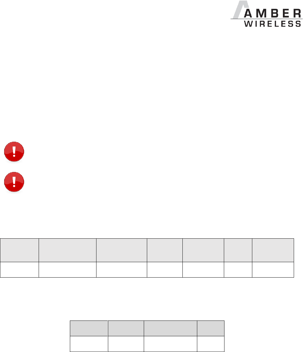
AMB2621_MA_2_4 Page 74 of 128 Date: 03/2017
9 User settings
The settings described in this chapter are stored permanently in the module's flash memory.
Depending on their corresponding permissions, their current values can be read out by the
CMD_GET_REQ command or modified by the CMD_SET_REQ command. To do so the
corresponding settings index is used, which can be found in the primary table of each setting
description.
This settings cannot be accessed (read, write) from the Peripheral only mode introduced in a
fallow-up chapter.
The validity of the specified parameters is not verified. Incorrect values can result in
device malfunction.
After the modification of the non-volatile parameters, a reset will be necessary for the
changes to be applied.
9.1.1 FS_DeviceInfo: Read the chip type and OS version
Settings
index
Designation
Permissible
values
Default
value
Permissions
Stored
in
Number of
bytes
15
FS_DeviceInfo
-
-
read
Flash
12
This setting contains information about the chip type and the OS version. The value of
FS_DeviceInfo is composed of the following 4 sub parameters (ordered by appearance in the
response):
OS version
Build code
Package variant
Chip ID
2 Byte
4 Byte
2 Byte
4 Byte
OS version:
0x0081 : Softdevice S132 2.0.0
0x0088 : Softdevice S132 2.0.1
0x008C : Softdevice S132 3.0.0
0x0091 : Softdevice S132 3.1.0
Build code:
ASCII coded (see following Table nRF52832 IC revision overview)
Package variant:
0x2000 : QF
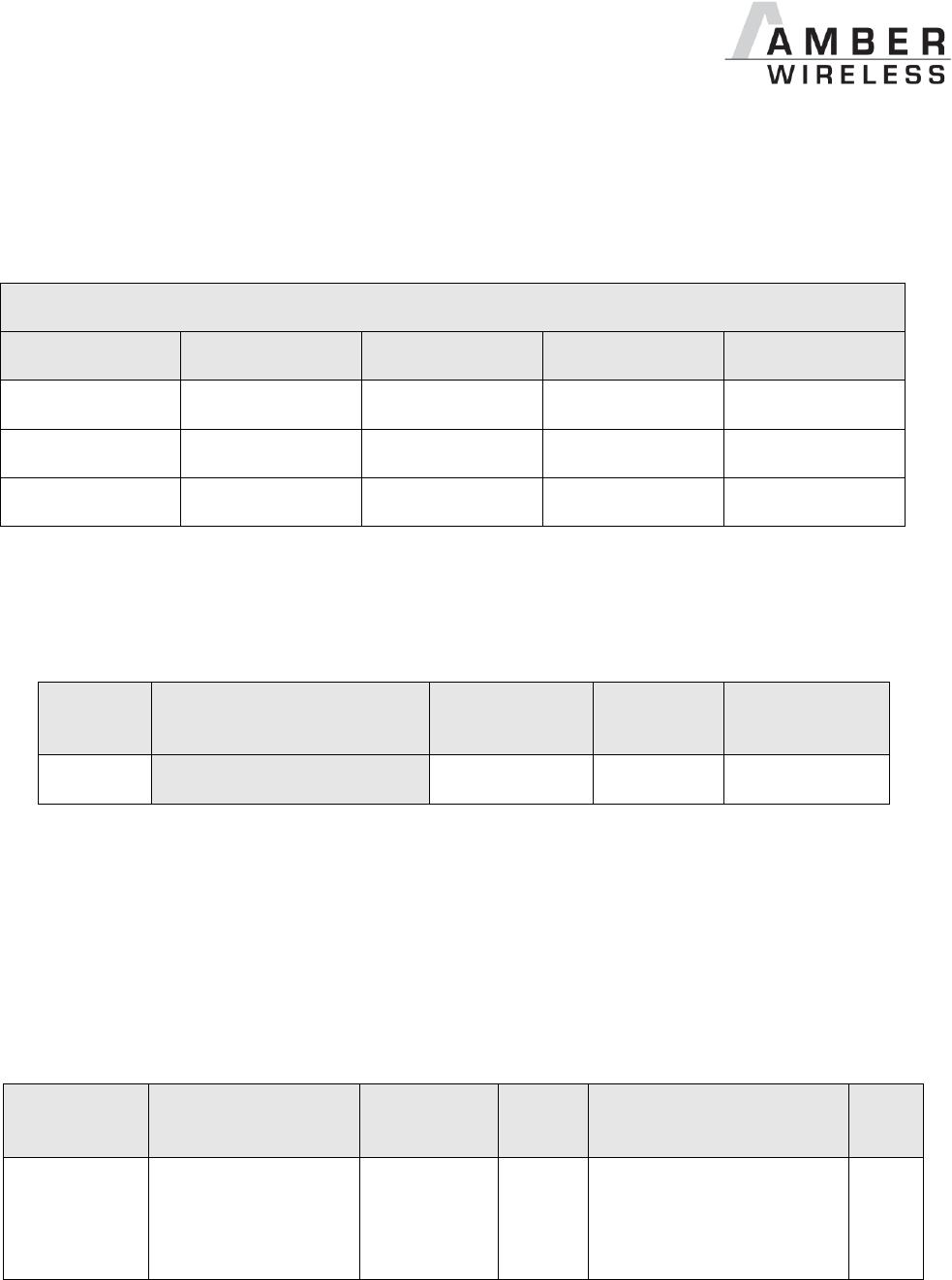
AMB2621_MA_2_4 Page 75 of 128 Date: 03/2017
0x2002 : CI
Chip ID:
0x00052832 : nRF52832
nRF52832 IC revision overview
Packet variant
Build code
Package
Flash size
RAM size
QF
AAB0
QFN48
512 kB
64 kB
QF
ABB0
QFN48
256 kB
32 kB
CI
AABA
WLCSP
512 kB
64 kB
9.1.1.1 Example 1
Request the device info of the module using CMD_GET_REQ with settings index 15
Start
signal
Command
Length
Settings
index
CS
0x02
0x10
0x01 0x00
0x0F
0x1C
Response CMD_GET_CNF: Successfully read out the device info (with byte order changed to
MSB first):
OS version = 0x0088 (Softdevice S132 2.0.1)
Build code = 0x41414241 (AABA)
Package variant = 0x2002 (CI)
Chip ID = 0x00052832
Please note that LSB is transmitted first in case of parameters with more than one byte length.
Start signal
Command | 0x40
Length
Status
Parameter
(Length - 1 byte)
CS
0x02
0x50
0x0D 0x00
0x00
0x88 0x00
0x41 0x42 0x41 0x41
0x02 0x20
0x32 0x28 0x05 0x00
0xE9
AMB2621_MA_2_4 Page 76 of 128 Date: 03/2017
9.1.2 FS_FWVersion: Read the firmware version
Settings
index
Designation
Permissible
values
Default
value
Permissions
Stored in
Number of
bytes
1
FS_FWVersion
-
-
read
Flash
3
This setting contains the firmware version of the module.
9.1.2.1 Example 1
Request the firmware version of the module using CMD_GET_REQ with settings index 1.
The firmware version consists of a 3 byte parameter.
Start
signal
Command
Length
Settings
index
CS
0x02
0x10
0x01 0x00
0x01
0x12
Response CMD_GET_CNF: Successfully read out the firmware version, for this example it is
0x000001 so “1.0.0” (with the parameter reverted to MSB first).
Start
signal
Command | 0x40
Length
Status
Parameter
(Length -1 Byte)
CS
0x02
0x50
0x04 0x00
0x00
0x00 0x00 0x01
0x57
AMB2621_MA_2_4 Page 77 of 128 Date: 03/2017
9.1.3 RF_DeviceName: Modify the device name
This parameter is using MSB first notation.
Settings index
Designation
Permissible values
Default value
Permissions
Stored in
Number of bytes
2
RF_DeviceName
See description
“A2621”
read/write
Flash
1-5
This parameter determines the name of the module which is used in the advertising packets to
identify the module on air. The permissible characters are in the range of 0x20 – 0x7E which
are special characters (see ASCII table), alphabetic characters (a-z and A-Z), numbers (0-9)
and whitespace.
The maximum size of this setting is 5 byte (due to packet size restrictions of BLE advertise
packets a longer name does not fit).
9.1.3.1 Example 1
Set the device name of the module to 0x4D 0x4F 0x44 0x20 0x31 = “MOD 1” using
CMD_SET_REQ with settings index 2.
Start signal
Command
Length
Settings index
Parameter
(Length -1 byte)
CS
0x02
0x11
0x06 0x00
0x02
0x4D 0x4F 0x44 0x20 0x31
0x40
Response CMD_SET_CNF: Successfully modified the setting.
Start signal
Command | 0x40
Length
Status
CS
0x02
0x51
0x01 0x00
0x00
0x52

AMB2621_MA_2_4 Page 78 of 128 Date: 03/2017
9.1.3.2 Example 2
Request the device name of the module using CMD_GET_REQ with settings index 2
Start signal
Command
Length
Settings index
CS
0x02
0x10
0x01 0x00
0x02
0x11
Response CMD_GET_CNF: Successfully read out the module name
0x41 0x32 0x36 0x32 0x31 = “A2621”
Start
signal
Command | 0x40
Length
Status
Parameter
(Length -1 byte)
CS
0x02
0x50
0x06 0x00
0x00
0x41 0x32 0x36 0x32 0x31
0x12
AMB2621_MA_2_4 Page 79 of 128 Date: 03/2017
9.1.4 FS_MAC: Read the MAC address
Settings
index
Designation
Permissible
values
Default
value
Permissions
Stored in
Number of
bytes
3
FS_MAC
-
-
read
Flash
6
This setting contains the unique MAC address of the module.
9.1.4.1 Example 1
Request the MAC address of the module using CMD_GET_REQ with settings index 3
Start signal
Command
Length
Settings index
CS
0x02
0x10
0x01 0x00
0x03
0x10
Response CMD_GET_CNF: Successfully read out the MAC address 0x55 0x93 0x19 0x6E 0x5B
0x87
Start signal
Command | 0x40
Length
Status
Parameter
(Length -1 byte)
CS
0x02
0x50
0x07 0x00
0x00
0x55 0x93 0x19 0x6E 0x5B 0x87
0x38
AMB2621_MA_2_4 Page 80 of 128 Date: 03/2017
9.1.5 FS_BTMAC: Read the BLE conform MAC address
Settings
index
Designation
Permissible
values
Default
value
Permissions
Stored in
Number of
bytes
4
FS_BTMAC
-
-
read
Flash
6
This setting contains the BLE conform MAC address of the module. The FS_BTMAC is
introduced and used to find the respective device on the RF-interface. It consists of the Amber
wireless company ID 0x0018DA followed by the FS_SerialNumber of the module. Please
note that LSB is transmitted first in all commands.
9.1.5.1 Example 1
Request the Bluetooth-conform MAC of the module using CMD_GET_REQ with settings index 4
Start
signal
Command
Length
Settings
index
CS
0x02
0x10
0x01 0x00
0x04
0x17
Response CMD_GET_CNF: Successfully read out the BLE conform MAC address
0x11 0x00 0x00 0xDA 0x18 0x00.
Accordingly, the FS_SerialNumber of this module is 0x000011 (17 decimal).
Start signal
Command | 0x40
Length
Status
Parameter (Length - 1 byte)
CS
0x02
0x50
0x07 0x00
0x00
0x11 0x00 0x00 0xDA 0x18 0x00
0x86
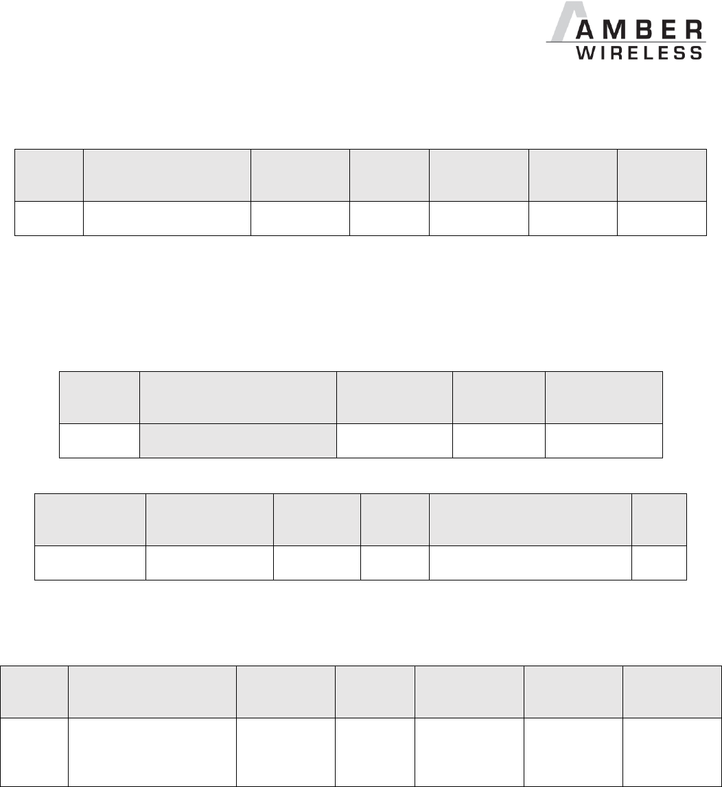
AMB2621_MA_2_4 Page 81 of 128 Date: 03/2017
9.1.6 FS_SerialNumber: Read the serial number of the module
Settings
index
Designation
Permissible
values
Default
value
Permissions
Stored in
Number of
bytes
16
FS_SerialNumber
-
-
read
Flash
3
This setting contains the serial number of the module.
9.1.6.1 Example 1
Request the serial number of the module using CMD_GET_REQ with settings index 16
Start
signal
Command
Length
Settings
index
CS
0x02
0x10
0x01 0x00
0x10
0x03
Response CMD_GET_CNF: Successfully read out the serial number, it is 0.0.11
Start signal
Command | 0x40
Length
Status
Parameter
(Length -1 byte)
CS
0x02
0x50
0x04 0x00
0x00
0x11 0x00 0x00
0x57
9.1.7 RF_OwnLTK: Modify the security key of the current device
Settings
index
Designation
Permissible
values
Default
value
Permissions
Stored in
Number of
bytes
5
RF_OwnLTK
See
description
“AMB_
DEFAULT
_KEY”
read/write
Flash
7-16
This setting determines the long term key of the current module. In security mode “LTK” (see
RF_SecFlags), this key is used, when another device sets up an encrypted connection to the
current module. The key used by the peer device must coincide with the RF_OwnLTK to setup
an encrypted connection. Otherwise, the connection request is refused.
The permissible characters are ASCII characters ranging from (hexadecimal) 0x21 to 0x7E
(both included) which are special characters, alphabetic characters (a-z and A-Z) and numbers
(0-9).
Please refer to your preferred ASCII table for reference of all allowed characters and use 0x21
and 0x7E to find the allowed range of characters.
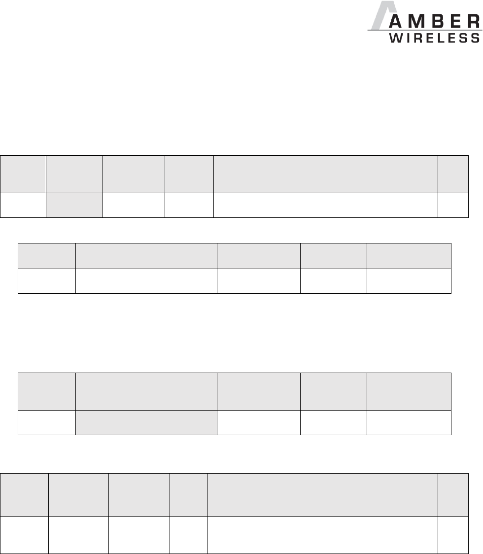
AMB2621_MA_2_4 Page 82 of 128 Date: 03/2017
9.1.7.1 Example 1
Set the own long term key of the module to 0x78 0x56 0x45 0x37 0x78 0x7A 0x41 = “xVE7xzA”
using CMD_SET_REQ with settings index 5
Start
signal
Command
Length
Settings
index
Parameter
(Length -1 byte)
CS
0x02
0x11
0x08 0x00
0x05
0x78 0x56 0x45 0x37 0x78 0x7A 0x41
0x01
Response CMD_SET_CNF: Successfully modified the setting.
Start
signal
Command | 0x40
Length
Status
CS
0x02
0x51
0x01 0x00
0x00
0x52
9.1.7.2 Example 2
Request the own long term key of the module using CMD_GET_REQ with settings index 5
Start
signal
Command
Length
Settings
index
CS
0x02
0x10
0x01 0x00
0x05
0x16
Response CMD_GET_CNF: Successfully read out the key as 0x41 0x4D 0x42 0x5F 0x44 0x45
0x46 0x41 0x55 0x4C 0x54 0x5F 0x4B 0x45 0x59 = “AMB_DEFAULT_KEY”
Start
signal
Command
| 0x40
Length
Status
Parameter
(Length -1 byte)
CS
0x02
0x50
0x10 0x00
0x00
0x41 0x4D 0x42 0x5F 0x44 0x45 0x46 0x41
0x55 0x4C 0x54 0x5F 0x4B 0x45 0x59
0x10

AMB2621_MA_2_4 Page 83 of 128 Date: 03/2017
9.1.8 RF_PeerLTK: Modify the security key to setup connections
Setting
s index
Designation
Permissible
values
Default
value
Permissions
Stored in
Number of
bytes
6
RF_PeerLTK
See
description
“AMB_
DEFAUL
T_KEY”
read/write
Flash /
RAM
7-16
This setting determines the long term key that is used to setup an encrypted connection to
another device, when security mode “LTK” (see RF_SecFlags) was selected. The key used by
the peer device must coincide with the RF_PeerLTK to setup an encrypted connection.
Otherwise, the connection request is refused.
The permissible characters are ASCII characters ranging from (hexadecimal) 0x21 to 0x7E
(both included) which are special characters, alphabetic characters (a-z and A-Z) and numbers
(0-9).
Please refer to your preferred ASCII table for reference of all allowed characters and use 0x21
and 0x7E to find the allowed range of characters.
9.1.8.1 Example 1
Set the peer long term key of the module to 0x78 0x56 0x45 0x37 0x78 0x7A 0x41 = “xVE7xzA”
using CMD_SET_REQ with settings index 6
Start
signal
Command
Length
Settings
index
Parameter
(Length -1 byte)
CS
0x02
0x11
0x08 0x00
0x06
0x78 0x56 0x45 0x37 0x78 0x7A 0x41
0x02
Response CMD_SET_CNF: Successfully modified the setting.
Start
signal
Command | 0x40
Length
Status
CS
0x02
0x51
0x01 0x00
0x00
0x52
9.1.8.2 Example 2
Request the peer long term key of the module using CMD_GET_REQ with settings index 6

AMB2621_MA_2_4 Page 84 of 128 Date: 03/2017
Start
signal
Command
Length
Settings
index
CS
0x02
0x10
0x01 0x00
0x06
0x15
Response CMD_GET_CNF: Successfully read out the key as 0x41 0x4D 0x42 0x5F 0x44 0x45
0x46 0x41 0x55 0x4C 0x54 0x5F 0x4B 0x45 0x59 = “AMB_DEFAULT_KEY”
Start
signal
Command
| 0x40
Length
Status
Parameter
(Length -1 byte)
CS
0x02
0x50
0x10 0x00
0x00
0x41 0x4D 0x42 0x5F 0x44 0x45 0x46 0x41
0x55 0x4C 0x54 0x5F 0x4B 0x45 0x59
0x10
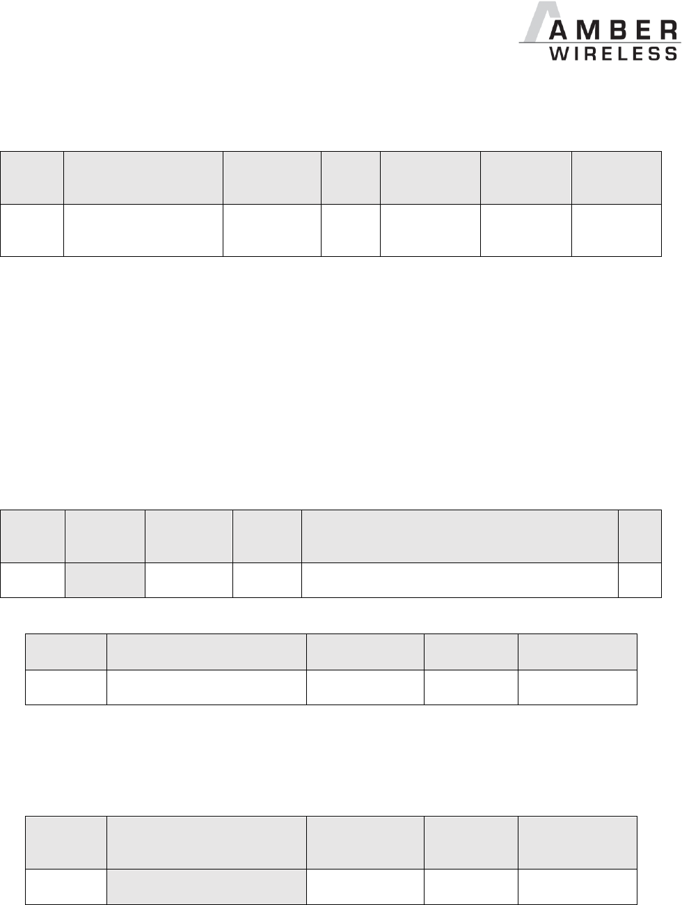
AMB2621_MA_2_4 Page 85 of 128 Date: 03/2017
9.1.9 RF_StaticPasskey: Modify the static pass key to setup connections
Setting
s index
Designation
Permissible
values
Default
value
Permissions
Stored in
Number of
bytes
18
RF_StaticPasskey
See
description
“12312
3”
read/write
Flash /
RAM
6
This setting determines the static pass key of the peripheral device used for authentication. If
the static pass key security mode is enabled by the peripheral, this key must be entered in the
central device. In case of an AMB2621 central, the command to enter this pass key during
connection setup is the CMD_PASSKEY_REQ.
The permissible characters are ranging from 0x30 to 0x39 (both included) which are ASCII
numbers (0-9). This is due to the fact that mobile phones prefer numbers only for the passkey.
9.1.9.1 Example 1
Set the static pass key of the module to 0x31 0x32 0x33 0x34 0x35 0x36 = “123456” using
CMD_SET_REQ with settings index 18
Start
signal
Command
Length
Settings
index
Parameter
(Length -1 byte)
CS
0x02
0x11
0x07 0x00
0x12
0x31 0x32 0x33 0x34 0x35 0x36
0x01
Response CMD_SET_CNF: Successfully modified the setting.
Start
signal
Command | 0x40
Length
Status
CS
0x02
0x51
0x01 0x00
0x00
0x52
9.1.9.2 Example 2
Request the static pass key of the module using CMD_GET_REQ with settings index 18
Start
signal
Command
Length
Settings
index
CS
0x02
0x10
0x01 0x00
0x12
0x01
Response CMD_GET_CNF: Successfully read out the key as 0x31 0x32 0x33 0x34 0x35 0x36 =
“123456”

AMB2621_MA_2_4 Page 86 of 128 Date: 03/2017
Start
signal
Command | 0x40
Length
Status
Parameter
(Length -1 byte)
CS
0x02
0x50
0x07
0x00
0x00
0x31 0x32 0x33 0x34 0x35 0x36
0x52
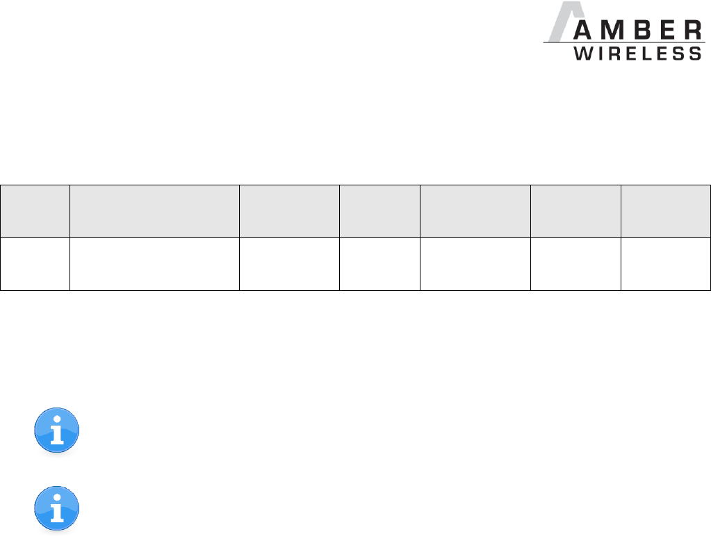
AMB2621_MA_2_4 Page 87 of 128 Date: 03/2017
9.1.10 RF_SecFlags: Modify the security settings
Settings
index
Designation
Permissible
values
Default
value
Permissions
Stored in
Number of
bytes
12
RF_SecFlags
See
description
0
read/write
Flash
1
This 8-bit field configures security settings of the module. Chapter 6.5.1 contains further
information about secure connections.
When connecting from an AMB2621 to another AMB2621, be sure that the same
security mode is used.
When connecting from a foreign device to an AMB2621, the peripheral (AMB2621)
determines the minimum security level needed for communication. So configure the
RF_SecFlags of the peripheral to set the desired security level.

AMB2621_MA_2_4 Page 88 of 128 Date: 03/2017
Bit no.
Description
2 : 0
Security mode configuration. Depending on its value, different modes are chosen
when setting up a secure connection.
In firmware version 2.1.0 and newer the peripheral decides which is the minimum
security level to access its data.
0x0
No
security
Data is transmitted without authentication and encryption.
0x1
LTK
Level 1.3
A fixed long term key (LTK) is used for encrypting the data.
This key is not exchanged by the RF-interface and has to
correlate on both of the connected devices. If the keys do not
match, the connection will be rejected.
This mode is only available/recommended for the
connection between two AMB2621 modules. When
communicating to a foreign device, please use another
security mode.
0x2
Just
works
Level 1.2
Each time a connection is established, new random keys are
exchanged in advance to use them for data encryption. This
mode uses the “just works” method.
0x3
Static
pass key
Level 1.3
For authentication the RF_StaticPasskey is used. If the
peripheral uses this method, the central device must enter the
correct pass key to finalize the connection.
others
Reserved
15 : 3
Reserved
Table 5 Security configuration flags
9.1.10.1 Example 1
Set the security flags to 0x01, to use the long term key for transmission encryption, using
CMD_SET_REQ with settings index 12
Start signal
Command
Length
Settings index
Parameter
(Length -1 byte)
CS
0x02
0x11
0x02 0x00
0x0C
0x01
0x1C
Response CMD_SET_CNF: Successfully modified the setting.

AMB2621_MA_2_4 Page 89 of 128 Date: 03/2017
Start
signal
Command | 0x40
Length
Status
CS
0x02
0x51
0x01 0x00
0x00
0x52
9.1.10.2 Example 2
Request the security flags of the module using CMD_GET_REQ with settings index 12
Start
signal
Command
Length
Settings
index
CS
0x02
0x10
0x01 0x00
0x0C
0x1F
Response CMD_GET_CNF: Successfully read out the value 2, which means that the pairing
mode is enabled.
Start signal
Command | 0x40
Length
Status
Parameter
(Length -1 byte)
CS
0x02
0x50
0x02 0x00
0x00
0x02
0x52
AMB2621_MA_2_4 Page 90 of 128 Date: 03/2017
9.1.11 RF_SecFlagsPerOnly: Modify the security settings (Peripheral only mode)
Settings
index
Designation
Permissible
values
Default
value
Permissions
Stored in
Number of
bytes
44
RF_SecFlags
See
description
3
read/write
Flash
1
Please refer to the setting RF_SecFlags for more details.
This setting is only used in peripheral only mode.
9.1.11.1 Example 1
Set the security flags to 0x02 to use the just works pairing, using CMD_SET_REQ with settings
index 12
Start signal
Command
Length
Settings index
Parameter
(Length -1 byte)
CS
0x02
0x11
0x02 0x00
0x2C
0x02
0x3F
Response CMD_SET_CNF: Successfully modified the setting.
Start
signal
Command | 0x40
Length
Status
CS
0x02
0x51
0x01 0x00
0x00
0x52
9.1.11.2 Example 2
Request the security flags of the module using CMD_GET_REQ with settings index 44
Start
signal
Command
Length
Settings
index
CS
0x02
0x10
0x01 0x00
0x2C
0x3F
Response CMD_GET_CNF: Successfully read out the value 2, which means that the pairing
mode is enabled.

AMB2621_MA_2_4 Page 91 of 128 Date: 03/2017
Start signal
Command | 0x40
Length
Status
Parameter
(Length -1 byte)
CS
0x02
0x50
0x02 0x00
0x00
0x02
0x52

AMB2621_MA_2_4 Page 92 of 128 Date: 03/2017
9.1.12 RF_ScanFlags: Modify the scan behaviour
Settings
index
Designation
Permissible
values
Default
value
Permissions
Stored in
Number of
bytes
13
RF_ScanFlags
See
description
0
read/write
Flash
1
This 8-bit field configures the scan behaviour of the module. To use multiple settings, add the bit
numbers and choose the result as value for RF_ScanFlags.
Bit no.
Description
0
If this bit is set, an active scan is performed when using CMD_SCANSTART_REQ. In
this case, after receiving an advertising packet a scan request is send to the
advertising module that returns a scan response containing additional information.
For the communication of AMB2621 modules, active scanning is only needed when
using Beacons. In this case, it is enabled automatically by the firmware.
Please note that active scanning increases the current consumption.
15 : 1
Reserved
Table 6 Scan configuration flags
9.1.12.1 Example 1
Set the scan flags to 0x01 to enable active scanning using CMD_SET_REQ with settings index
13
Start signal
Command
Length
Settings index
Parameter
(Length -1 byte)
CS
0x02
0x11
0x02 0x00
0x0D
0x01
0x1D
Response CMD_SET_CNF: Successfully modified the setting.
Start
signal
Command | 0x40
Length
Status
CS
0x02
0x51
0x01 0x00
0x00
0x52
9.1.12.2 Example 2
Request the scan flags of the module using CMD_GET_REQ with settings index 13

AMB2621_MA_2_4 Page 93 of 128 Date: 03/2017
Start
signal
Command
Length
Settings
index
CS
0x02
0x10
0x01 0x00
0x0D
0x1E
Response CMD_GET_CNF: Successfully read out the value 0, which means that active scan is
disabled.
Start signal
Command | 0x40
Length
Status
Parameter
(Length -1 byte)
CS
0x02
0x50
0x02 0x00
0x00
0x00
0x50
AMB2621_MA_2_4 Page 94 of 128 Date: 03/2017
9.1.13 RF_BeaconFlags: Interpret the advertising data
Settings
index
Designation
Permissible
values
Default
value
Permissions
Stored in
Number
of bytes
14
RF_BeaconFlags
See
description
0
read/write
Flash
1
This 8-bit field enables/disables the reception of Beacons. To use multiple settings, add the bit
numbers and choose the result as value for RF_BeaconFlags.
Bit no.
Description
1 : 0
Enable/disable the reception of Beacons. To avoid too much traffic on the UART, we
recommend to use the filtered version.
00
0x0
Reception of Beacons disabled.
01
0x1
Receive all Beacons from AMB2621 devices in range. Each
received packet is interpreted and outputted by the UART.
In this case, active scanning is performed which increases the
current consumption.
To decrease the work load of the receiving module, use a
sufficiently high UART baud rate at the receiving device and slow
advertising intervals at the sending devices.
11
0x3
Same as ‘01’ plus additional filter. This filter discards redundant
packets that contain the same content.
2
If this bit is set, a CMD_RSSI_IND message is outputted each time when an
advertising packet with AMBER UUID is received. This feature can be used to
realize a position sensing application, since the CMD_RSSI_IND contains the current
TX power level and the current RSSI value besides the FS_BTMAC of the sending
device.
To decrease the work load of the receiving module, please use a sufficiently high
UART baud rate at the receiving device and slow advertising intervals at the sending
devices.
15 : 3
Reserved
Table 7 Beacon configuration flags
AMB2621_MA_2_4 Page 95 of 128 Date: 03/2017
The internal database of the module may host the advertising data of 25 different
devices. If the data base is full, the oldest entry is removed.
To avoid too much traffic the usage of slow advertising intervals is recommended.
9.1.13.1 Example 1
Set the Beacon flags to 0x04 using CMD_SET_REQ with settings index 14. Thus when an
advertising packet with AMBER UUID is received, a CMD_RSSI_IND message is printed.
Start
signal
Command
Length
Settings
index
Parameter
CS
0x02
0x11
0x02 0x00
0x0E
0x04
0x1B
Response CMD_SET_CNF: Successfully modified the setting.
Start
signal
Command | 0x40
Length
Status
CS
0x02
0x51
0x01 0x00
0x00
0x52
9.1.13.2 Example 2
Request the Beacon flags of the module using CMD_GET_REQ with settings index 14
Start
signal
Command
Length
Settings
index
CS
0x02
0x10
0x01 0x00
0x0E
0x1D
Response CMD_GET_CNF: Successfully read out the value 3, which means that the reception of
Beacons is enabled and double packets are filtered by the module.
Start signal
Command | 0x40
Length
Status
Parameter
(Length -1 byte)
CS
0x02
0x50
0x02 0x00
0x00
0x03
0x53
AMB2621_MA_2_4 Page 96 of 128 Date: 03/2017
9.1.14 RF_AdvertisingTimeout: Modify the advertising timeout
Settings
index
Designation
Permissible
values
Default
value
Permissions
Stored in
Number of
bytes
7
RF_AdvertisingTime
out
0 (infinite)
1 – 65535
0
read/write
Flash
2
This parameter defines the time in seconds after which the advertising of the module stops. If
no peer connects before this timeout, advertising stops and the module goes to system-off
mode.
If the RF_AdvertisingTimeout is set to 0, the module advertises infinitely.
To ensure that the module sends a sufficient amount of advertising packets per
RF_AdvertisingTimeout, please also check the RF_ScanTiming parameter,
which defines the frequency of advertising packets.
9.1.14.1 Example 1
Set the advertising timeout parameter to 0x00 0xB4 (180s) using CMD_SET_REQ with settings
index 7.
Start
signal
Command
Length
Settings
index
Parameter
CS
0x02
0x11
0x03 0x00
0x07
0xB4 0x00
0xA3
Response CMD_SET_CNF: Successfully modified the setting.
Start
signal
Command | 0x40
Length
Status
CS
0x02
0x51
0x01 0x00
0x00
0x52
9.1.14.2 Example 2
Request the advertising timeout of the module using CMD_GET_REQ with settings index 7
Start
signal
Command
Length
Settings
index
CS
0x02
0x10
0x01 0x00
0x07
0x14
Response CMD_GET_CNF: Successfully read out the value 0x00 0x00 = 0s, which indicates
indefinite advertising.

AMB2621_MA_2_4 Page 97 of 128 Date: 03/2017
Start signal
Command | 0x40
Length
Status
Parameter
(Length -1 byte)
CS
0x02
0x50
0x03 0x00
0x00
0x00 0x00
0x51
AMB2621_MA_2_4 Page 98 of 128 Date: 03/2017
9.1.15 RF_ScanFactor: Modify the scan factor
Settings
index
Designation
Permissible
values
Default
value
Permissions
Stored in
Number of
bytes
10
RF_ScanFactor
1 – 10
2
read/write
Flash
1
This parameter defines the factor between the scan window and the scan interval. See
RF_ScanTiming for more information.
Example: Let’s assume that the scan window is 50ms, the RF_ScanFactor is 3, then the
module scans for 50ms on a fixed channel, enters a suspend mode (system-on mode) for
100ms (3•50ms - 50ms), switches the channel, again scans for 50ms and so on.
The larger the RF_ScanFactor, the less time the module scans and thus the less power is
consumed, but also the more difficult it is to detect other BLE devices on air.
9.1.15.1 Example 1
Set the scan factor to 0x03 using CMD_SET_REQ with settings index 10.
Start signal
Command
Length
Settings index
Parameter
(Length -1 byte)
CS
0x02
0x11
0x02 0x00
0x0A
0x03
0x18
Response CMD_SET_CNF: Successfully modified the setting.
Start
signal
Command | 0x40
Length
Status
CS
0x02
0x51
0x01 0x00
0x00
0x52
9.1.15.2 Example 2
Request the scan factor of the module using CMD_GET_REQ with settings index 10
Start
signal
Command
Length
Settings
index
CS
0x02
0x10
0x01 0x00
0x0A
0x19
Response CMD_GET_CNF: Successfully read out the value 2.
Start signal
Command | 0x40
Length
Status
Parameter
(Length -1 byte)
CS
0x02
0x50
0x02 0x00
0x00
0x02
0x52
AMB2621_MA_2_4 Page 99 of 128 Date: 03/2017
9.1.16 RF_ScanTiming: Modify the scan timing settings
Settings
index
Designation
Permissible
values
Default
value
Permissions
Stored in
Number
of bytes
9
RF_ScanTiming
0 – 5
1
read/write
Flash
1
The RF_ScanTiming enables the possibility to configure the timing behaviour of the module’s
RF interface during advertising and scanning state. Using this parameter several predefined
configurations can be chosen, which include timing parameters, such as the frequency of
advertising packets and the length of a scan window.
The choice of the RF_ScanTiming primarily affects the latency of device detection on air as
well as the current consumption. The lower the RF_ScanTiming, the faster the modules can
find each other for communication, but also the more power will be consumed.
RF_ScanTiming
0
1
2
3*
4*
5*
Advertising interval
[ms]
20
40
250
1000
5000
10240
Scan window
[ms]
25
50
312
1250
6250
10240
Scan interval
[ms]
Defined by the RF_ScanFactor.
Connection setup
timeout [s]
1
2
2
5
20
35
Current
consumption
*Mainly suitable for transmitting data using Beacons without consuming much energy.
Further information:
In ACTION_SCANNING mode, the scan interval defines the time after which the module
switches channel to detect other BLE devices in range. See also RF_ScanFactor.
In ACTION_SCANNING mode, the scan window defines the section of the scan interval,
where the module is scanning. During the remaining time, the module enters a suspend
mode (system-on mode). See also RF_ScanFactor.
AMB2621_MA_2_4 Page 100 of 128 Date: 03/2017
In ACTION_IDLE mode, the advertising interval defines the time after which the module
periodically sends its advertising packet. In between, the module enters a suspend mode
(system-on mode).
The connection setup timeout defines the time after which a connection request has to
be answered by the peripheral.
Please ensure that all members of a network support the same advertising and scan
timing parameters.
To ensure that the module is allowed to send a sufficient amount of advertising
packets, please also check the RF_AdvertisingTimeout parameter.
To connect to an Android or iOS device, please first review their supported settings [1].
9.1.16.1 Example 1
Set the scan timing parameter to 0x00 using CMD_SET_REQ with settings index 9.
Start
signal
Command
Length
Settings
index
Parameter
CS
0x02
0x11
0x02 0x00
0x09
0x00
0x18
Response CMD_SET_CNF: Successfully modified the setting.
Start
signal
Command | 0x40
Length
Status
CS
0x02
0x51
0x01 0x00
0x00
0x52
9.1.16.2 Example 2
Request the scan timing parameter of the module using CMD_GET_REQ with settings index 9
Start
signal
Command
Length
Settings
index
CS
0x02
0x10
0x01 0x00
0x09
0x1A
Response CMD_GET_CNF: Successfully read out the value 4.
Start signal
Command | 0x40
Length
Status
Parameter
(Length -1 byte)
CS
0x02
0x50
0x02 0x00
0x00
0x04
0x54
AMB2621_MA_2_4 Page 101 of 128 Date: 03/2017
9.1.17 RF_ConnectionTiming: Modify the connection timing settings
Settings
index
Designation
Permissible
values
Default
value
Permissions
Stored in
Number of
bytes
8
RF_ConnectionTiming
0 – 6
1
read/write
Flash
1
The RF_ConnectionTiming enables the possibility to configure the timing behaviour of the
module’s RF interface during an established connection. Using this parameter several
predefined configurations can be chosen, which include the minimum and maximum connection
interval, as well as the connection supervision timeout.
The choice of the RF_ConnectionTiming primarily determines how rapidly the connection is
established and data is transmitted. The lower the RF_ConnectionTiming, the more
frequently the connected devices communicate with each other and thus, the more power is
consumed.
RF_ConnectionTiming
0
1
2
3
4
5
6
Minimum connection
interval [ms]
8
20
50
200
750
2000
8
Maximum connection
interval [ms]
30
75
250
1000
2250
4000
8
Connection supervision
timeout [s]
4
4
4
8
15
25
4
Maximum throughput*
[kB/s]
Up to
3.97
Up to
1.7
Up to
0.51
-
-
-
Up to
4.5
Current consumption
*Measured with 230400 baud UART baud rate and payload size of 128Bytes between two
AMB2621 modules.
More information:
The minimum and maximum connection interval parameters specify the borders of the
connection interval as determined in the negotiation procedure between the central and
the peripheral during connection setup. The connection interval defines the frequency of
communication during connection setup and data transmission.
AMB2621_MA_2_4 Page 102 of 128 Date: 03/2017
If an AMB2621 module A (central) connects to an AMB2621 module B (peripheral), the
connection interval settings of the central are used for connection setup. If both modules
have different connection interval settings the peripheral requests the central to accept
the peripheral’s settings after 5s. The central accepts these settings, and thus the
peripheral’s connection interval is used.
If now another BLE device (e.g. a smart phone) connects as central to an AMB2621
module (peripheral) and the connection interval settings do not coincide, the AMB2621
requests the smart phone to accept its settings after 5s. If the cell phone does not accept
the settings, it will be requested a further 3 times with a delay of 10s. If the peripheral’s
settings request have been rejected in all cases the connection will be shut down. If the
smart phone itself requests to update the connection interval of the AMB2621, the
module accepts the request.
Reversely, if an AMB2621 (central) connects to another BLE device (peripheral) and the
connection interval settings do not coincide, the AMB2621 accepts all requests of the
peripheral to update the connection parameter settings.
The connection supervision timeout defines the time after which an already established
connection is considered as lost, when no further communication has occurred.
Please ensure that all members (AMB2621s, cell phones and other BLE devices) of a
network use the same connection timing parameters to avoid connection problems and
changes of the connection interval during an opened connection.
To connect to an Android or iOS device, please first review their supported settings [1].
The minimal value of the minimum connection interval that is supported by iOS is
30ms!
9.1.17.1 Example 1
Set the connection factor to 0x00 using CMD_SET_REQ with settings index 8.
Start signal
Command
Length
Settings index
Parameter
(Length -1 byte)
CS
0x02
0x11
0x02 0x00
0x08
0x00
0x19
Response CMD_SET_CNF: Successfully modified the setting.

AMB2621_MA_2_4 Page 103 of 128 Date: 03/2017
Start
signal
Command | 0x40
Length
Status
CS
0x02
0x51
0x01 0x00
0x00
0x52
9.1.17.2 Example 2
Request the connection timing parameter of the module using CMD_GET_REQ with settings
index 8
Start
signal
Command
Length
Settings
index
CS
0x02
0x10
0x01 0x00
0x08
0x1B
Response CMD_GET_CNF: Successfully read out the value 1.
Start signal
Command | 0x40
Length
Status
Parameter
(Length -1 byte)
CS
0x02
0x50
0x02 0x00
0x00
0x01
0x51

AMB2621_MA_2_4 Page 104 of 128 Date: 03/2017
9.1.18 RF_TXPower: Modify the output power
Setting
s index
Designation
Permissible
values
Default
value
Permissions
Stored in
Number
of bytes
17
RF_TXPower
See
description
4
read/write
Flash
1
This setting determines the output power in dBm of the module. The value has to be entered in
hexadecimal and as two’s complement. The permissible values are listed in the following table.
Permissible values
Decimal [dBm]
-40
-30
-20
-16
-12
-8
-4
0
+4
Two’s complement,
hexadecimal
0xD8
0xE2
0xEC
0xF0
0xF4
0xF8
0xFC
0x00
0x04
9.1.18.1 Example 1
Set the output power of the module to -8 dBm, which is 0xF8 in two’s complement notation,
using CMD_SET_REQ with settings index 17
Start
signal
Command
Length
Settings
index
Parameter
CS
0x02
0x11
0x02 0x00
0x11
0xF8
0xF8
Response CMD_SET_CNF: Successfully modified the setting.
Start
signal
Command | 0x40
Length
Status
CS
0x02
0x51
0x01 0x00
0x00
0x52
9.1.18.2 Example 2
Request the output power of the module using CMD_GET_REQ with settings index 17
Start
signal
Command
Length
Settings
index
CS
0x02
0x10
0x01 0x00
0x11
0x02
Response CMD_GET_CNF: Successfully read out the value 0x04 = 4dBm

AMB2621_MA_2_4 Page 105 of 128 Date: 03/2017
Start signal
Command | 0x40
Length
Status
Parameter
(Length -1 byte)
CS
0x02
0x50
0x02 0x00
0x00
0x04
0x54
AMB2621_MA_2_4 Page 106 of 128 Date: 03/2017
9.1.19 UART_BaudrateIndex: Configure the UART speed
Settings
index
Designation
Permissible
values
Default
value
Permissions
Stored
in
Number of
bytes
11
UART_BaudrateIndex
See description
3
read/write
Flash
1
This parameter defines the baud rate used by the module’s UART.
Possible values are:
UART_BaudrateIndex
0
1
2
3
4
Rate [Baud]
9600
19200
38400
115200
230400
After changing the baud rate using the CMD_SET_REQ the module restarts using the
new baud rate. Therefore don’t forget to update the baud rate of the connected host to
be able to further use the module’s UART.
Please note that due to the HF-activity of the chip, single bytes on the UART can get
lost, when using a very fast UART data rate. In case of corrupted UART
communication the module cannot interpret the sent request and thus does not return
a confirmation.
9.1.19.1 Example 1
Set the baud rate index to 0x04 (230400 Baud) using CMD_SET_REQ with settings index 11.
Start signal
Command
Length
Settings index
Parameter
(Length -1 byte)
CS
0x02
0x11
0x02 0x00
0x0B
0x04
0x1E
Response CMD_SET_CNF: Successfully modified the setting.
Start signal
Command | 0x40
Length
Status
CS
0x02
0x51
0x01 0x00
0x00
0x52
9.1.19.2 Example 2
Request the baud rate index of the module using CMD_GET_REQ with settings index 11

AMB2621_MA_2_4 Page 107 of 128 Date: 03/2017
Start signal
Command
Length
Settings index
CS
0x02
0x10
0x01 0x00
0x0B
0x18
Response CMD_GET_CNF: Successfully read out the value 0x03, which equals 115200 Baud.
Start signal
Command | 0x40
Length
Status
Parameter
(Length -1 byte)
CS
0x02
0x50
0x02 0x00
0x00
0x03
0x53

AMB2621_MA_2_4 Page 108 of 128 Date: 03/2017
9.2 List of user settings
Settings
index
Designation
Summary
Permissible
values
Default
value
Permissions
Stored
in
Number
of bytes
1
FS_FWVersion
Version of the firmware
-
-
read
Flash
3
2
RF_DeviceName
Name of the module
See description
“A2621”
read/write
Flash
1-5
3
FS_MAC
MAC address of the
module
-
-
read
Flash
6
4
FS_BTMAC
BLE conform MAC
address of the module
-
-
read
Flash
6
5
RF_OwnLTK
Long term key used
when it is connected by
another device
See description
“AMB_DEF
AULT_KEY”
read/write
Flash
7-16
6
RF_PeerLTK
Long term key used to
connect to another
device
See description
“AMB_DEF
AULT_KEY”
read/write
Flash /
RAM
7-16
7
RF_AdvertisingTimeout
Time [s] after
advertising stops. LSB
first
0 (infinite)
1 – 65535
0
read/write
Flash
2
8
RF_ConnectionTiming
Module connection
timing configuration
0 – 6
1
read/write
Flash
1
9
RF_ScanTiming
Module advertising and
scanning timing
configuration
0 – 5
1
read/write
Flash
1
10
RF_ScanFactor
Factor between scan
interval and scan
window
1 – 10
2
read/write
Flash
1
11
UART_BaudrateIndex
Baud rate of the UART
See description
3
read/write
Flash
1
12
RF_SecFlags
Security settings of the
module
See description
0
read/write
Flash
1
13
RF_ScanFlags
Scan settings of the
module
See description
0
read/write
Flash
1
14
RF_BeaconFlags
Beacon settings of the
module
See description
0
read/write
Flash
1
15
FS_DeviceInfo
Information about the
chip
-
-
read
Flash
12
16
FS_SerialNumber
Serial number of the
module
-
-
read
Flash
3
17
RF_TXPower
Output power [dBm]
Two’s complement
See description
4
read/write
Flash
1

AMB2621_MA_2_4 Page 109 of 128 Date: 03/2017
Settings
index
Designation
Summary
Permissible
values
Default
value
Permissions
Stored
in
Number
of bytes
18
RF_StaticPasskey
6 digit pass key
See description
“123123”
read/write
Flash
6
44
RF_SecFlagsPerOnly
Security settings of the
module (peripheral only
mode only)
See description
3
read/write
Flash
1
Table 8 Table of settings

AMB2621_MA_2_4 Page 110 of 128 Date: 03/2017
10 Peripheral only mode
The version 3.0.0 of the AMB2621 implements a new feature, that allows the easy integration of
the AMB2621 BLE module to an already existing host. The peripheral only mode offers a plug
and play installation without previous configuration of the AMB2621. It is tailored for easy
communication with mobile BLE devices like smart phones.
10.1 What the peripheral only mode is
The peripheral only mode is a special operation mode, that uses the user settings and the
peripheral functions of the normal mode described in the previous chapters.
It has to be enabled during the module start-up and contains the following key features:
Peripheral only functions: The AMB2621 only contains the functions of a peripheral.
Thus it is advertising until another BLE devices connects to it. In this case the UART of
the AMB2621 is enabled, the LED_2 pin shows that the channel is open and
bidirectional data transmission can start. As soon as the connection is closed, the UART
is disabled again to save power.
Since all central functions are no longer valid, the module cannot initiate any connection
or run scans.
Transparent UART interface: The serial interface of the AMB2621 is no longer driven by
commands. This means, when the UART of the module is enabled (i.e. only when a
channel is open, indicated by both LEDs active), data sent to the UART is transmitted by
the AMB2621 to the connected BLE device. On the other hand, all data received by RF
is send from the AMB2621 to the connected host without additional header bytes.
Please have in mind that the connecting smart phone must support and initiate larger
MTU sizes when payload sizes of more than 19 Byte shall be used. Additional bytes will
be discarded without notice to the host.
The data sent to the UART is buffered in the AMB2621 up to a maximum payload
depending on of the current channel MTU. When no new byte was received for 20ms,
the data will be transmitted by RF to the connected BLE device.
The UART is only running, when a channel is open. Thus power is saved during the
advertising period.
Depending on the configured connection interval, only one packet per interval is allowed
to be transmitted.
Since the commands of the command interface are no longer valid, a AMB2621 cannot
be configured when running in peripheral only mode.
Pairing: The default security mode is the static passkey pairing method (see
RF_SecFlagsPerOnly), with the default key “123123”.
10.2 Reasons to use the peripheral only mode
The AMB2621 peripheral only mode equips custom applications with a BLE interface (to be
accessible by other BLE devices) without installation effort.
To setup a connection to the AMB2621 in peripheral only mode the central device has to insert
the AMB2621’s static passkey. As soon as the channel to a connected BLE central device is

AMB2621_MA_2_4 Page 111 of 128 Date: 03/2017
open, the LED_2 pin switches on to signalize that data can be exchanged now. When the
connection was shut down by the BLE central device, the LED_2 pin switches off again.
Due to the transparent UART interface, data can be exchanged without additional headers.
Furthermore, the peripheral only mode allows an energy efficient operation of the BLE interface,
since the UART is only enabled when it is really used.
10.3 How to use the peripheral only mode
The peripheral only mode is enabled, when a high signal is present on the OPERATION MODE
pin during device start-up or reset.
No configuration of the module is needed for this operating mode. The module shall be set to
factory settings if reconfigured before so it uses the default user settings. In this case the UART
uses 115200Baud 8n1 and static passkey pairing is used as authentication method.
If a configuration of the module is still needed (e.g. when another UART baud rate needs to be
chosen), the module has to be started in normal mode and the CMD_SET_REQ may be used to
update the user settings.
The user shall not change any other of the user settings but the following two parameters:
RF_UARTBaudrateIndex (change the UART baud rate, default value “115200”)
RF_StaticPasskey (change the default static passkey, default value “123123”)
Only changes (in comparison to the factory settings) in the two parameters
RF_UARTBaudrateIndex and RF_StaticPasskey are allowed.
In case the module has been configured with other non-default user settings, while the
command mode was used, a CMD_FACTORYRESET_REQ is mandatory before
activating the peripheral only mode.
On the central side (e.g. smart phone), the AMBER SPP like profile has to be implemented in a
customer application. For more information, see the “AMB2621 Advanced developer guide” and
the application note AMB2621_AN003 that explains the general connection.
10.4 More information
The maximum payload supported by an open channel depends on the connected central
device. The AMB2621 supports up to 128 Byte payload (corresponding to a MTU of 132
Byte), which may be negotiated by the central device (using a MTU request). If no MTU
request is requested by the connecting central device the value of 19 Bytes payload per
packet and connection interval as given by the BT 4.0 standard is used (compatibility
mode to BLE 4.0 devices). Data received by the AMB2621’s UART, that exceeds the
maximum payload size of the open channel, is discarded. In peripheral only mode, (due
to the deactivated commands) the AMB2621 cannot inform its host about the maximum
payload size or of payload discarding.
The connecting device could implement a function to inform the host behind the
AMB2621 which MTU the channel is capable of. Until this message is received, the host
shall assume a payload capability of up to 19 Byte.

AMB2621_MA_2_4 Page 112 of 128 Date: 03/2017
Only in peripheral only mode, the name of the device is now longer the 5-digit
RF_DeviceName that is saved in the user settings. The new 8-digit device name is “A-
123456” in case of the module has the FS_BTMAC 0x0018DA123456. This is a
workaround for iOS which does not allow access to the BT-MAC for received BT frames.
The content of the advertising packet was changed in peripheral only mode. The TX
power information block was removed, as the device name was extended to 8 digits.

AMB2621_MA_2_4 Page 113 of 128 Date: 03/2017
11 Firmware update
The AMB2621 offers two possibilities of updating its firmware, namely wired or wireless.
The firmware of the AMB2621 consists of 3 parts, the OTA-bootloader, the Softdevice
and the application. Ensure that after updating the firmware all parts are still existent.
11.1 Firmware update using the SWD interface
To update the firmware of the AMB2621 the SWD interface of the module and a supported
flasher hardware (such as SEGGER J-Link plus) can be used. Therefore the pins GND, VCC,
RESET, SWDIO and SWDCLK of the module have to be accessible and connected to the
flasher hardware accordingly (corresponding documentation of flasher has to be read for further
information). After the connection of a flash adapter to this SWD interface, the new firmware can
be flashed using the corresponding PC software nrfjprog.exe available directly from Nordic
Semiconductor.
nrfjprog.exe -–family NRF52 --chiperase --program AMB2621.hex
For this reason a .hex-file can be provided, which contains all firmware parts (bootloader,
Softdevice, application). The name of the hex file has to be adopted accordingly in the
command line above.
This is the only method by which the module could be recovered in the event of a
serious software fault or corrupted memory. This method is fail-safe.
11.2 Firmware update using the AMB2621 OTA bootloader
The second method offers a possibility to update the firmware over the air (OTA). Therefore, the
Nordic nRF52 BLE DFU Bootloader is integrated into the AMB2621’s firmware, which will
communicate over the BLE interface.
The OTA bootloader mode is a distinct operating mode besides the normal operating modes
mentioned before.
For this reason, a .zip-file can be provided, which contains all (bootloader, Softdevice,
application) parts of the firmware in an encrypted and authenticated package.
To start the bootloader, one of the following two conditions has to be satisfied:
1. send the command CMD_BOOTLOADER_REQ to the module to restart in bootloader mode
2. during a reset and while restarting, a low signal has to be present on the BOOT pin of
the module to start it in bootloader mode
The bootloader mode has started successfully if LED_1 has turned on.
AMB2621_MA_2_4 Page 114 of 128 Date: 03/2017
After the bootloader has started successfully, the module goes into the advertising mode using
the name “DFU2621”. Now, any BLE device hosting an application that understands the
commands of the Nordic nRF52 BLE DFU Bootloader can connect in order to update the
AMB2621 firmware.
The DFU application of the AMB2621 Toolbox App is such an application. For more details,
please refer to the AMB2621 Toolbox Quick Start Guide. As an alternative the plain apps from
Nordic Semiconductor “nRF Toolbox” can be used.
Version of the
firmware before the
update
Version of the new
firmware
Version of the AMB2621 Toolbox App
(Android)
1.0.0 – 1.1.0
1.0.0 – 1.1.0
1.16.2, 1.18.4
1.0.0 – 1.1.0
2.1.0
Not supported
due to S132 update and BL changes
2.1.0
2.1.0
1.18.4
2.1.0, 3.0.0
3.0.0
1.18.4 or
Nordic nRF Toolbox 2.2.1
Table 9 Compatibility matrix
As soon as a connection has been set up, LED_1 turns off again and LED_2 turns on.
The implemented Nordic nRF52 BLE DFU bootloader uses a dual bank method to
update the firmware. Thus the old firmware is only replaced once the new firmware has
been transferred successfully. This prevents the module from being flashed with a
faulty firmware.
An OTA firmware update will take several minutes to be performed, the duration is also
dependant how much of the firmware shall be updated (application only or complete
update).
The max connection interval of the update service is set to 30ms. Please check
whether your mobile supports this speed.
This method is only applicable if the AMB2621 still contains an intact bootloader. In
order to be able to recover a faulty module, we recommend to have access to the
relevant JTAG pins required to perform a wired firmware update (see chapter 11.1).
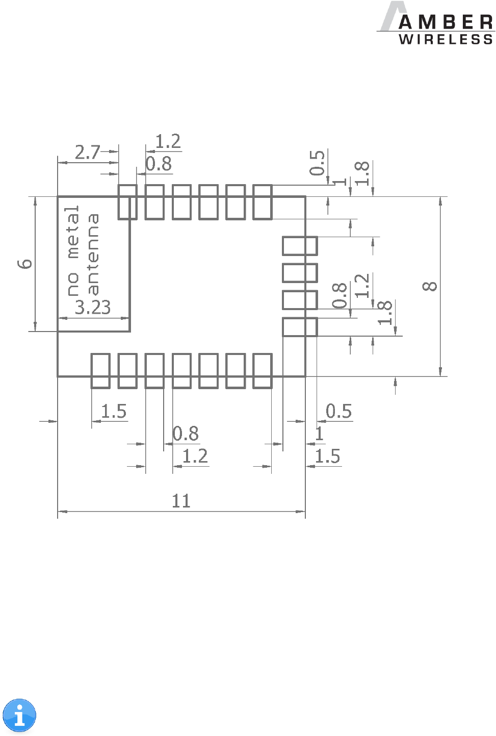
AMB2621_MA_2_4 Page 115 of 128 Date: 03/2017
12 Hardware integration
12.1 Footprint
Figure 5 Footprint
Dimensions in mm.
12.2 General advice for schematic and layout
For less experienced RF users it is advisable to closely copy the relating evaluation board with
respect to schematic and layout, as it is a proven design. The layout should be conducted with
particular care, because even small deficiencies could affect the radio performance and its
range or even the conformity.
The following general advice should be taken into consideration:
Radio performance parameters, such as sensitivity, may be affected by high frequency
digital I/O with large sink/source current close to the radio, power supply and antenna
pins.
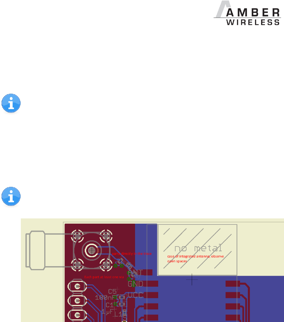
AMB2621_MA_2_4 Page 116 of 128 Date: 03/2017
A clean power supply is strongly recommended. Interference, especially oscillation can
severely restrain range and conformity.
Variations in voltage should be avoided.
LDOs, properly designed in, usually deliver a proper regulated voltage.
Blocking capacitors and a ferrite bead in the power supply line can be included to filter
and smoothen the supply voltage when necessary.
No fixed values can be recommended, as these depend on the circumstances of the
application (main power source, interferences etc.).
Elements for ESD protection should be placed on all Pins that are accessible from the
outside and should be placed close to the accessible area. For example, the RF-Pin is
accessible when using an external antenna and should be protected.
ESD protection for the antenna connection must be chosen such as to have a minimum
effect on the RF signal. For example, a protection diode with low capacitance such as
the LXES15AAA1-100 or a 68 nH air-core coil connecting the RF-line to ground give
good results.
Placeholders for optional antenna matching or additional filtering are recommended.
Again, no fixed values can be recommended, as they depend on the influencing
circumstances of the application (antenna, interferences etc.).
Figure 6: Layout
To avoid the risk of short circuits and interference there should be no routing underneath
the module on the top layer of the printed circuit board.
On the second layer, a ground plane is recommended, to provide good grounding and
shielding to any following layers and application environment.
In case of integrated antennas, it is required to have areas free from ground. This area
should be copied from the evaluation board (respectively Figure 5).
The area with the integrated antenna must overlap with the carrier board and should not
protrude, as it is matched to be placed directly on top of a PCB.
Modules with integrated antennas should be placed with the antenna at the edge of the
main board. It should not be placed in the middle of the main board or far away from the
edge. This is to avoid tracks being placed beside the antenna.
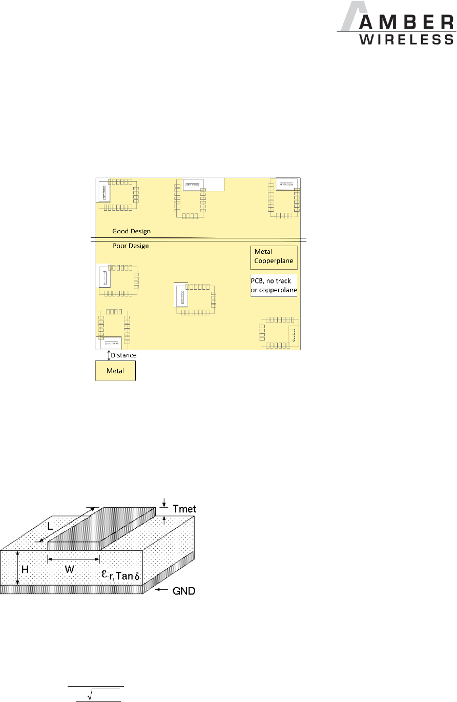
AMB2621_MA_2_4 Page 117 of 128 Date: 03/2017
Filter and blocking capacitors should be placed directly in the tracks without stubs, to
achieve the best effect.
Antenna matching elements should be placed close to the antenna/connector and
blocking capacitors close to the module.
Ground connections for the module and the capacitors should be kept as short as
possible and with at least one separate through hole connection to the ground layer.
ESD protection elements should be placed as close as possible to the exposed areas.
Figure 7: Placement of the module
12.3 Dimensioning of the 50 Ohm micro strip
The antenna track has to be designed as a 50 Ohm feed line.
Figure 8 Dimensioning the antenna feed line as micro strip
The width W for a micro strip can be calculated using the following equation:
met
T
e
H
Wr
87
41.150
98.5
25.1
Equation 1 Parameters of the antenna feeding line

AMB2621_MA_2_4 Page 118 of 128 Date: 03/2017
Example: a FR4 material with r = 4.3, a height H = 1000 µm and a copper thickness of Tmet= 18
µm will lead to a trace width of W ~ 1.9 mm. To ease the calculation of the micro strip line (or
e.g. a coplanar) many calculators can be found in the internet.
As rule of thumb a distance of about 3 x W should be observed between the micro strip
and other traces / ground.
The micro strip refers to ground, therefore there has to be the ground plane underneath
the trace.
Keep the feeding line as short as possible.
12.4 Antenna solutions
There exist several kinds of antennas, which are optimized for different needs. Chip antennas
are optimized for minimal size requirements but at the expense of range, PCB antennas are
optimized for minimal costs, and are generally a compromise between size and range. Both
usually fit inside a housing. Range optimization in general is at the expense of space. Antennas
that are bigger in size, so that they would probably not fit in a small housing, are usually
equipped with a RF connector. A benefit of this connector may be to use it to lead the RF signal
through a metal plate (e.g. metal housing, cabinet).
As a rule of thumb a minimum distance of λ /10 (3.5 cm @ 868 MHz, 1.2 cm @ 2.44 GHz) from
the antenna to any other metal should be kept. Metal placed further away will not directly
influence the behaviour of the antenna, but will never the less produce shadowing.
Keep the antenna away from large metal objects as far as possible to avoid
electromagnetic field blocking.
In the following chapters, some special types of antenna are described.
12.4.1 Lambda/4 radiator
An effective antenna is a λ/4 radiator. The simplest realization is an 8.6 cm long piece of wire for
868 MHz, respectively a 3.1 cm long piece of wire for 2.44 GHz. This radiator needs a ground
plane at its feeding point. Ideally, it is placed vertically in the middle of the ground plane. As this
is often not possible because of space requirements, a suitable compromise is to bend the wire
away from the PCB respective to the ground plane. The λ/4 radiator has approximately 40 Ohm
input impedance, therefore matching is not required.
12.4.2 Chip antenna
There are many chip antennas from various manufacturers. The benefit of a chip antenna is
obviously the minimal space required and reasonable costs. However, this is often at the
expense of range. For the chip antennas, reference designs should be followed as closely as
possible, because only in this constellation can the stated performance be achieved.

AMB2621_MA_2_4 Page 119 of 128 Date: 03/2017
12.4.3 PCB antenna
PCB antenna designs can be very different. The special attention can be on the miniaturization
or on the performance. The benefits of the PCB antenna are their minimal (if PCB space is
available) costs, however the evaluation of a PCB antenna holds more risk of failure than the
use of a finished antenna. Most PCB antenna designs are a compromise of range and space
between chip antennas and connector antennas.
12.4.4 Antennas provided by AMBER
12.4.4.1 AMB1926
The AMB1926 is a 2.4 GHz antenna with SMA connection and swivel base.
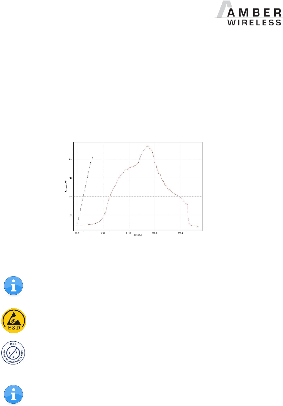
AMB2621_MA_2_4 Page 120 of 128 Date: 03/2017
13 Manufacturing information
The assembly contains moisture sensitive devices of the MSL classification 3. Only the
dry packed Tape & Reel devices (AMB2621-TR) are suitable for the immediate
processing in a reflow process.
Further information concerning the handling of moisture sensitive devices, (e.g. drying)
can be obtained from the IPC/ JEDEC J-STD-033.
Recommendations for the temperature profile for the soldering furnace cannot be made,
as it depends on the substrate board, the number and characteristics of the
components, and the soldering paste used (consult your EMS).
Figure 9 shows a soldering curve that had been used for a 31 cm² carrier board for single-side
assembly.
Figure 9 Example of a temperature profile
Caution: Must be adjusted to the characteristics of the carrier board!
To ensure the mechanical stability of the modules it is recommended to solder all
pads of the module to the base board, even if they are not used for the application.
Caution! ESD sensitive device.
Care should be taken when handling the device in order to prevent permanent
damage.
MSL 3
Caution! This assembly contains moisture sensitive components.
Care should be taken when processing the device according to IPC/JEDEC J-STD-
033.
Since the module itself is not fused the voltage supply shall be fed from a limited
power source according to clause 2.5 of EN 60950-1.


AMB2621_MA_2_4 Page 122 of 128 Date: 03/2017
15 Firmware history
Version 0.x.x
Pre-Release for test run
Version 1.0.0
First production release
New command interface with 2 Byte length field
using Softdevice 2.0.1 + SDK 11.0
SPP-Like Protocol
Known issues: CMD_SET_REQ does not run with parameter RF_AdvertisingTimeout
Version 1.0.1
Fixed issues:
o CMD_SET_REQ does not run with parameter RF_AdvertisingTimeout
UART checks for max buffer size
Known issues: None
Version 1.1.0
Fixed issues:
o DCDC enabled for lowest power consumption
Known issues: None
Version 2.1.0
Change notes:
o Using Softdevice 3.0.0 and SDK 12.1.0
o Remove UART baud rates faster than 230400 baud to prevent lost bytes
o due to DMA usage the UART current is increased (without DMA the UART data rate
must be decreased further below 230400 baud)
o Introduced CMD_ERROR_IND message indicating internal error states
o Introduced support for transmission of large BLE packets (19 bytes payload → 128Bytes
payload). This is a non-mandatory BLE 4.2 feature. Use CMD_DATA_REQ command to
send long packets if it is indicated by the CMD_CHANNELOPEN_RSP.
o Modified the CMD_CHANNELOPEN_RSP indication the max. supported payload size
o CMD_DATA_REQ returns maximum supported payload size if it was exceeded
o Modified RF_ConnectionTiming profile 0 and added profile 6
o Modified the CMD_SECURITY_IND message
o DTM uses max packet size for TX test packets (255 bytes)
o Parameter RF_SecLTK replaced by RF_OwnLTK and RF_PeerLTK
o Added commands CMD_SET_RAM_REQ and CMD_GET_RAM_REQ to set/get volatile RAM
parameter values (only RF_PeerLTK at the moment)
o Moved the settings index of parameter RF_TXPower
o New OTA bootloader
o AMB2621 Toolbox App version 1.18.4 must be used to update the firmware
o CMD_DATAEX_REQ removed due to incompatibilities with foreign BLE devices
o Added new security concept. Now the peripheral decides whether the security level is
sufficient.
o Added new security mode in RF_SecFlags (Static pass key method was added)
o New user setting RF_StaticPasskey added
o New commands CMD_PASSKEY_REQ and CMD_PASSKEY_IND added
Known issues:
o OTA update from version 1.1.0 to 2.1.0 not supported
o Compatibility of version 2.1.0 to older versions only given when no security mode is
enabled

AMB2621_MA_2_4 Page 123 of 128 Date: 03/2017
Version 3.0.0
Change notes:
o Using Softdevice 3.1.0 and SDK 12.1.0
o Changed default value of user setting parameter RF_AdvertisingTimeout from
180s to 0s. This means, that in default configuration the module does not go to sleep
after 180s as in the previous firmware versions.
o Function of LED_2 has changed. Now it indicates whether a channel is open or not.
o Introduced new operation mode “Peripheral only mode” with special behaviour
Introduced new Advertise format containing the LSBs of the MAC address (only
for Peripheral only mode)
Introduced PIN “OPERATION MODE“ to enable the Peripheral only mode, as an
internal pull-down is used the “do not connect if not needed” still applies for
normal mode operation
Introduced a transparent UART interface (only available for this mode)
Introduced a new user setting RF_SecFlagsPerOnly
Known issues:
o OTA update from version 1.x.x to 3.0.0 not supported

AMB2621_MA_2_4 Page 124 of 128 Date: 03/2017
16 License information
The AMB2621 firmware contains the following software or software-parts provided by Nordic
Semiconductor:
„S132 Softdevice“ which is the actual BLE 4.2 Stack in a binary format
nRF5 SDK containing drivers, library’s and source code example projects
Those software parts are allowed to be used only on Nordic Semiconductor hardware.
For complete license information (“NORDIC SEMICONDUCTOR STANDARD SOFTWARE
LICENSE AGREEMENT“) please refer to the corresponding documents of Nordic
Semiconductors (e.g. S132 Softdevice 3.1.0 or nRF5 SDK 12.1.0).
All other firmware components are property of AMBER wireless GmbH.
17 Bluetooth SIG listing & qualification
Each product containing intellectual property of the Bluetooth SIG must be listed and qualified
by the Bluetooth SIG. Due to the qualification of the AMB2621 as end product no further
Bluetooth tests are required.
Please refer to the testing laboratory of your choice for further more detailed information
regarding the listing of your product.
17.1 AMB2621 listing details
Declaration ID: D033500
QD ID: 90212
Specification Name: 4.2
Project Type: End product
Model Number: AMB2621
17.2 nRF52832 listing details
Nordic Bluetooth low energy QD ID: 80428 (nrf52832 CIAA using Softdevice S132 v3.x.x)

AMB2621_MA_2_4 Page 125 of 128 Date: 03/2017
18 Regulatory compliance information
18.1 Important notice
The use of RF frequencies is limited by national regulations. The AMB2621 has been designed
to comply with the R&TTE directive 1999/5/EC and the RED directive 2014/53/EU of the
European Union (EU).
The AMB2621 can be operated without notification and free of charge in the area of the
European Union. However, according to the R&TTE / RED directive, restrictions (e.g. in terms of
duty cycle or maximum allowed RF power) may apply.
Conformity assessment of the final product
The AMB2621 is a subassembly. It is designed to be embedded into other products (products
incorporating the AMB2621 are henceforward referred to as "final products").
It is the responsibility of the manufacturer of the final product to ensure that the final product is
in compliance with the essential requirements of the European Union's Radio &
Telecommunications Terminal Equipment (R&TTE) directiveor rather the Radio Equipment
Directive (RED).
The conformity assessment of the subassembly AMB2621 carried out by AMBER wireless
GmbH does not replace the required conformity assessment of the final product in accordance
to the R&TTE or rather the RED.
Exemption clause
Relevant regulation requirements are subject to change. AMBER wireless GmbH does not
guarantee the accuracy of the before mentioned information. Directives, technical standards,
procedural descriptions and the like may be interpreted differently by the national authorities.
Equally, the national laws and restrictions may vary with the country. In case of doubt or
uncertainty, we recommend that you consult with the authorities or official certification
organizations of the relevant countries. AMBER wireless GmbH is exempt from any
responsibilities or liabilities related to regulatory compliance.
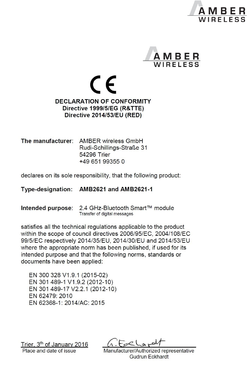
AMB2621_MA_2_4 Page 126 of 128 Date: 03/2017
18.2 Declaration of conformity

AMB2621_MA_2_4 Page 127 of 128 Date: 03/2017
18.3 FCC Compliance statement AMB2621
FCC ID: R7TAMB2621
This device complies with Part 15 of the FCC Rules.
Operation is subject to the following two conditions:
(1) this device may not cause harmful interference, and
(2) this device must accept any interference received, including interference that may
cause undesired operation.
(FCC 15.19)
Modifications (FCC 15.21)
Caution: Changes or modifications for this equipment not expressly approved by AMBER
wireless may void the FCC authorization to operate this equipment.
18.4 IC Compliance statement AMB2621
Certification Number: 5136A-AMB2621
This device complies with Industry Canada licence-exempt RSS standard(s). Operation is
subject to the following two conditions: (1) this device may not cause harmful interference, and
(2) this device must accept any interference received, including interference that may cause
undesired operation.
Le présent appareil est conforme aux CNR d'Industrie Canada applicables aux appareils radio
exempts de licence. L'exploitation est autorisée aux deux conditions suivantes : (1) l'appareil ne
doit pas produire de brouillage, et (2) l'utilisateur de l'appareil doit accepter tout brouillage
radioélectrique subi, même si le brouillage est susceptible d'en compromettre le
fonctionnement.

AMB2621_MA_2_4 Page 128 of 128 Date: 03/2017
19 Important information
19.1 Exclusion of liability
AMBER wireless GmbH presumes that the information in this document is correct at the time of
publication. However, AMBER wireless GmbH reserves the right to modify technical
specifications or functions of its products or discontinue the production of these products or the
support of one of these products without any written announcement or notification to customers.
The customer must make sure that the information used is valid. AMBER wireless GmbH does
not assume any liability for the use of its products. Amber wireless GmbH does not grant
licenses for its patent rights or for any other of its intellectual property rights or third-party rights.
Customers bear responsibility for compliance of systems or units in which AMBER wireless
products are integrated with applicable legal regulations.
19.2 Trademarks
AMBER wireless® is a registered trademark of AMBER wireless GmbH.
All other trademarks, registered trademarks, and product names are the exclusive property of
the respective owners.
19.3 Usage restriction
AMBER wireless products are not approved for use in life-supporting or life-sustaining systems
or units or other systems whose malfunction could result in serious bodily injury to the user.
Moreover, AMBER wireless products are not approved for use as key components of any life-
supporting or life-sustaining system or unit whose malfunction could result in the failure of the
life-supporting system or unit or could affect its safety or effectiveness. AMBER wireless
customers who use these products in such applications or sell them for such usage act at their
own risk and must relieve AMBER wireless GmbH from all damages that may result from the
sale for unsuitable purposes or unsuitable usage.
By using AMBER wireless products, the user agrees to these terms and conditions.
Copyright © 2017, AMBER wireless GmbH. All rights reserved.
AMBER wireless GmbH
Phone +49.651.993.550
Email info@amber-wireless.de
Internet www.amber-wireless.de