AMETEK Magnetrol USA R95 Fluid Level Radar Transmitter User Manual through air radar install
Magnetrol Fluid Level Radar Transmitter through air radar install
Exhibit D Users Manual per 2 1033 b3
Through-Air
Radar Level Transmitter
7xxx
6xxx
5xxx
4xxx
3xxx
2xxx
1xxx
Installation and Operating Manual
Model R95

Through-Air Radar Transmitter
Read this Manual Before Installing
This manual provides information on the Through-Air
Radar transmitter. It is important that all instructions
are read carefully and followed in sequence. The
QuickStart Installation instructions are a brief guide to
the sequence of steps for experienced technicians to fol-
low when installing the equipment. Detailed instruc-
tions are included in the Complete Installation section of
this manual.
Conventions Used in this Manual
Certain conventions are used in this manual to convey
specific types of information. General technical material,
support data, and safety information are presented in
narrative form. The following styles are used for notes,
cautions, and warnings.
Notes
Notes contain information that augments or clarifies
an operating step. Notes do not normally contain
actions. They follow the procedural steps to which
they refer.
Cautions
Cautions alert the technician to special conditions
that could injure personnel, damage equipment, or
reduce a component’s mechanical integrity. Cautions
are also used to alert the technician to unsafe prac-
tices or the need for special protective equipment or
specific materials. In this manual, a caution box indi-
cates a potentially hazardous situation which, if not
avoided, may result in minor or moderate injury.
Warnings
Warnings identify potentially dangerous situations or
serious hazards. In this manual, a warning indicates
an imminently hazardous situation which, if not
avoided, could result in serious injury or death.
Safety Messages
The Through-Air Radar system is designed for use in
Category II, Pollution Degree 2 installations. Follow all
standard industry procedures for servicing electrical and
computer equipment when working with or around high
voltage. Always shut off the power supply before touch-
ing any components. Although high voltage is not pres-
ent in this system, it may be present in other systems.
Electrical components are sensitive to electrostatic dis-
charge. To prevent equipment damage, observe safety
procedures when working with electrostatic sensitive
components.
This device complies with Part 15 of the FCC rules.
Operation is subject to the following two conditions:
(1) This device may not cause harmful interference,
and (2) This device must accept any interference
received, including interference that may cause
undesired operation.
FCC ID: LPN R95
Any unauthorized changes or modifications not
expressly approved by the party responsible for compli-
ance could void user’s authority to operate this equip-
ment.
WARNING! Explosion hazard. Do not connect or dis-
connect designs rated Explosion-proof or Non-incendive
unless power has been switched off and/or the area is
known to be non-hazardous
Notice of Copyright and Limitations
Copyright © 2002 Magnetrol International,
Incorporated
All rights reserved
Magnetrol reserves the right to make changes to the
product described in this manual at any time without
notice. Magnetrol makes no warranty with respect to
the accuracy of the information in this manual.
Warranty
All Magnetrol/STI electronic level and flow controls are
warranted free of defects in materials or workmanship for
one full year from the date of original factory shipment.
If returned within the warranty period; and, upon factory
inspection of the control, the cause of the claim is deter-
mined to be covered under the warranty; then,
Magnetrol/STI will repair or replace the control at no cost
to the purchaser (or owner) other than transportation.
Magnetrol/STI shall not be liable for misapplication,
labor claims, direct or consequential damage or expense
arising from the installation or use of equipment. There
are no other warranties expressed or implied, except spe-
cial written warranties covering some Magnetrol/STI
products.
Quality assurance
The quality assurance system in place at Magnetrol/STI
guarantees the highest level of quality
throughout the company. Magnetrol is
committed to providing full customer
satisfaction both in quality products and
quality service.
Magnetrol’s quality assurance system is
registered to ISO 9001 affirming its
commitment to known international quality standards
providing the strongest assurance of product/service
quality available.
1Through-Air Radar Transmitter
1.0 Complete Installation
This section provides detailed procedures for properly
installing, configuring, and, as needed, troubleshooting the
Through-Air Radar Level Transmitter.
1.1 Unpacking
Unpack the instrument carefully. Make sure all components
have been removed from the packing material. Check all the
contents against the packing slip and report any discrepancies
to the factory.
Before proceeding with the installation, do the following:
•Inspect all components for damage. Report any damage to
the carrier within 24 hours.
•Make sure the nameplate model number on the probe and
transmitter agree with the packing slip and purchase order.
•Record the model and serial numbers for future reference
when ordering parts.
1.2 Electrostatic Discharge (ESD)
Handling Procedure
Magnetrol’s electronic instruments are manufactured to the
highest quality standards. These instruments use electronic
components that may be damaged by static electricity pres-
ent in most work environments.
The following steps are recommended to reduce the risk of
component failure due to electrostatic discharge.
•Ship and store circuit boards in anti-static bags. If an anti-
static bag is not available, wrap the board in aluminum foil.
Do not place boards on foam packing materials.
•Use a grounding wrist strap when installing and removing
circuit boards. A grounded workstation is recommended.
•Handle circuit boards only by the edges. Do not touch
components or connector pins.
•Make sure that all electrical connections are completely
made and none are partial or floating. Ground all equip-
ment to a good, earth ground.

2
1.3 Before You Begin
1.3.1 Site Preparation
Each Through-Air Radar transmitter is built to match the
specific physical specifications of the required installation.
Make sure the antenna connection is correct for the threaded
or flanged mounting on the vessel or tank where the trans-
mitter will be placed. See Mounting, Section 1.4.
Make sure that the wiring between the power supply and
Through-Air Radar transmitter are complete and correct for
the type of installation.
When installing the Through-Air Radar transmitter in a
general purpose or hazardous area, all local, state, and federal
regulations and guidelines must be observed. See Wiring,
Section 1.5.
1.3.2 Equipment and Tools
No special equipment or tools are required to install the
Through-Air Radar transmitter. The following items are
recommended:
•Open-end wrenches or adjustable wrench to fit the process
connection size and type. Threaded antenna and transmitter
2"(51 mm), transmitter adjustment 11⁄4" (32 mm). A torque
wrench is highly desirable.
•Flat-blade screwdriver
•Digital multimeter or digital volt/ammeter
•24 VDC power supply, 23 mA
1.3.3 Operational Considerations
Operating specifications vary based on antenna type.
1.4 Mounting
The Through-Air Radar transmitter can be mounted to a
tank using a variety of process connections. Generally, either
a threaded or flanged connection is used.
Note: Do not place insulating material around any part of the
Through-Air Radar transmitter including the probe flange.
3
Make sure all mounting connections are properly in place
on the tank before installing the transmitter. Compare the
nameplate on the antenna and transmitter with the product
information; make sure the antenna type and mount are
correct for the intended installation.
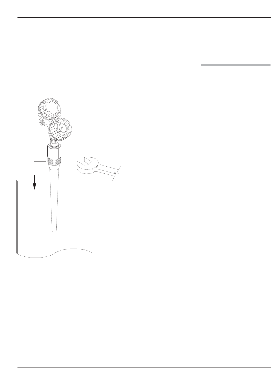
1.4.1 Installing the Transmitter
Before installing, make sure the:
•Model and serial numbers on the nameplates of the
antenna and transmitter are identical.
•Antenna has adequate room for installation.
•Process temperature, pressure, dielectric, and viscosity are
within the probe specifications for the installation.
To install the transmitter:
①Make sure the process connection is at least 11⁄2" NPT or a
flanged mounting.
②Carefully place the antenna into the vessel. Align the gasket
on flanged installations.
③Align the antenna process connection with the threaded or
flanged mounting on the vessel.
④For threaded connections, tighten the nut of the antenna
process connection. For flanged connections, tighten flange
bolts.
⑤Rotate the transmitter to face the most convenient direction
for wiring, configuration, and viewing.
②
①
④
③
Through-Air Radar Transmitter
1.5 Wiring
Caution The Through-Air Radar transmitter operates at volt-
ages of 20-36 VDC (GP), 20-28.6 VDC (IS) and 20-36
VDC (XP). Higher voltage will damage the transmitter.
Wiring between the power supply and the Through-Air
Radar transmitter should be made using 18-22 AWG
shielded twisted pair instrument cable. Within the trans-
mitter enclosure, connections are made to the terminal
strip and the ground connections. The directions for
wiring the Through-Air Radar transmitter depend on the
application:
•General Purpose or Non-incendive (Cl I, Div. 2)
•Intrinsically Safe
•Explosion Proof
WARNING! Explosion hazard. Do not disconnect equipment
unless power has been switched off or the area is
known to be non-hazardous.
1.5.1 General Purpose or Non-incendive (Cl I, Div. 2)
A general purpose installation does not have flammable
media present. Areas rated non-incendive (Cl I, Div. 2)
have flammable media present only under abnormal con-
ditions. No special electrical connections are required. If
flammable media is contained in the vessel, the transmitter
must be installed per Cl I, Div. 1 standards of
area classification.
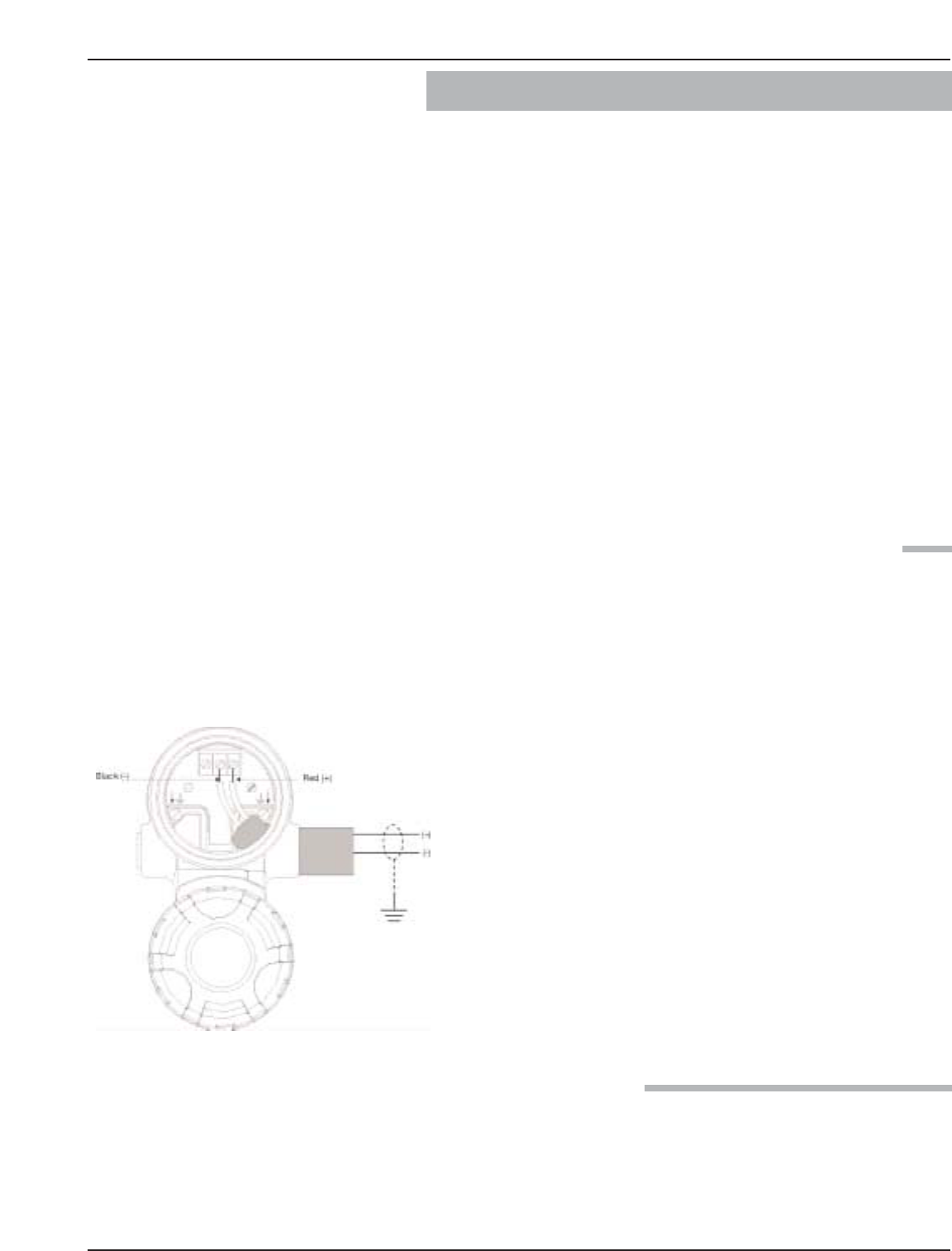
To install General Purpose or Non-incendive wiring:
1. Remove the cover to the wiring compartment of the trans-
mitter. Install the conduit plug in the unused opening.
2. Install a conduit fitting and pull the supply wires.
3. Connect shield to an earth ground at power supply and
leave floating at the transmitter.
4. Connect an earth ground wire to the nearest green ground
screw. (Not shown in illustration.)
5. Connect the positive supply wire to the (+) terminal and
the negative supply wire to the (-) terminal.
6. Replace the cover to the wiring compartment of the trans-
mitter.
1.5.2 Intrinsically Safe
An intrinsically safe (IS) installation potentially has flam-
mable media present. An approved IS barrier must be
installed in the non-hazardous (safe) area.
4

To install Intrinsically Safe wiring:
1. Make sure the IS barrier is properly installed in the safe
area (refer to local plant or facility procedures). Complete
the wiring from the barrier to the Through-Air Radar
transmitter.
2. Remove the cover to the wiring compartment of the trans-
mitter. Install the conduit plug in the unused opening.
3. Install a conduit fitting and pull the supply wires.
4. Connect shield to an earth ground at power supply and
leave floating at the transmitter.
5. Connect an earth ground wire to the nearest green ground
screw. (Not shown in illustration.)
6. Connect the positive supply wire to the (+) terminal and
the negative supply wire to the (-) terminal.
7. Replace the cover to the wiring compartment of the
transmitter.
1.5.3 Explosion Proof
Explosion Proof (XP) is a method of designing equipment
for installation in hazardous areas. A hazardous location is
an area in which flammable gases or vapors are, or may
be, present in the air in quantities sufficient to produce
explosive or ignitable mixtures. The wiring for the trans-
mitter must be contained in Explosion Proof conduit
extending into the safe area. Due to the specialized design
of the Through-Air Radar transmitter, no Explosion Proof
conduit fitting (EY seal) is required within 18" of the
transmitter. An Explosion Proof conduit fitting (EY seal)
is required between the hazardous and safe areas.
To install Explosion Proof wiring:
1. Install Explosion Proof conduit from the safe area to the
conduit connection of the Through-Air Radar transmitter
(refer to local plant or facility procedures).
2. Remove the cover to the wiring compartment of the
transmitter.
3. Connect shield to an earth ground at the power supply
and leave floating at the transmitter.
4. Connect an earth ground wire to the nearest green
ground screw. (Not shown in illustration.)
5. Connect the Intrinsic Safety (IS) terminal to ground per
NFPA 70, the CeC, or the local inspector.
6. Connect the positive supply wire to the (+) terminal and
the negative supply wire to the (-) terminal.
7. Replace the cover to the wiring compartment of the
transmitter.
5Through-Air Radar Transmitter
1.6 Configuring the Transmitter
The Through-Air Radar transmitter comes configured
from the factory and can be reconfigured in the shop.
Bench configuration provides a convenient and efficient
way to set up the transmitter before going to the tank site
to complete the installation.
Before configuring the transmitter, collect the operating
parameters information. Then, power-up the transmitter
on the bench and follow through the step-by-step proce-
dures for the menu-driven transmitter display. Information
on configuring the transmitter using a HART communica-
tor is given in Configuration Using HART.
1.6.1 Operating Parameters
Some key information is needed to calibrate the
Through-Air Radar transmitter. Complete the configura-
tion information table.
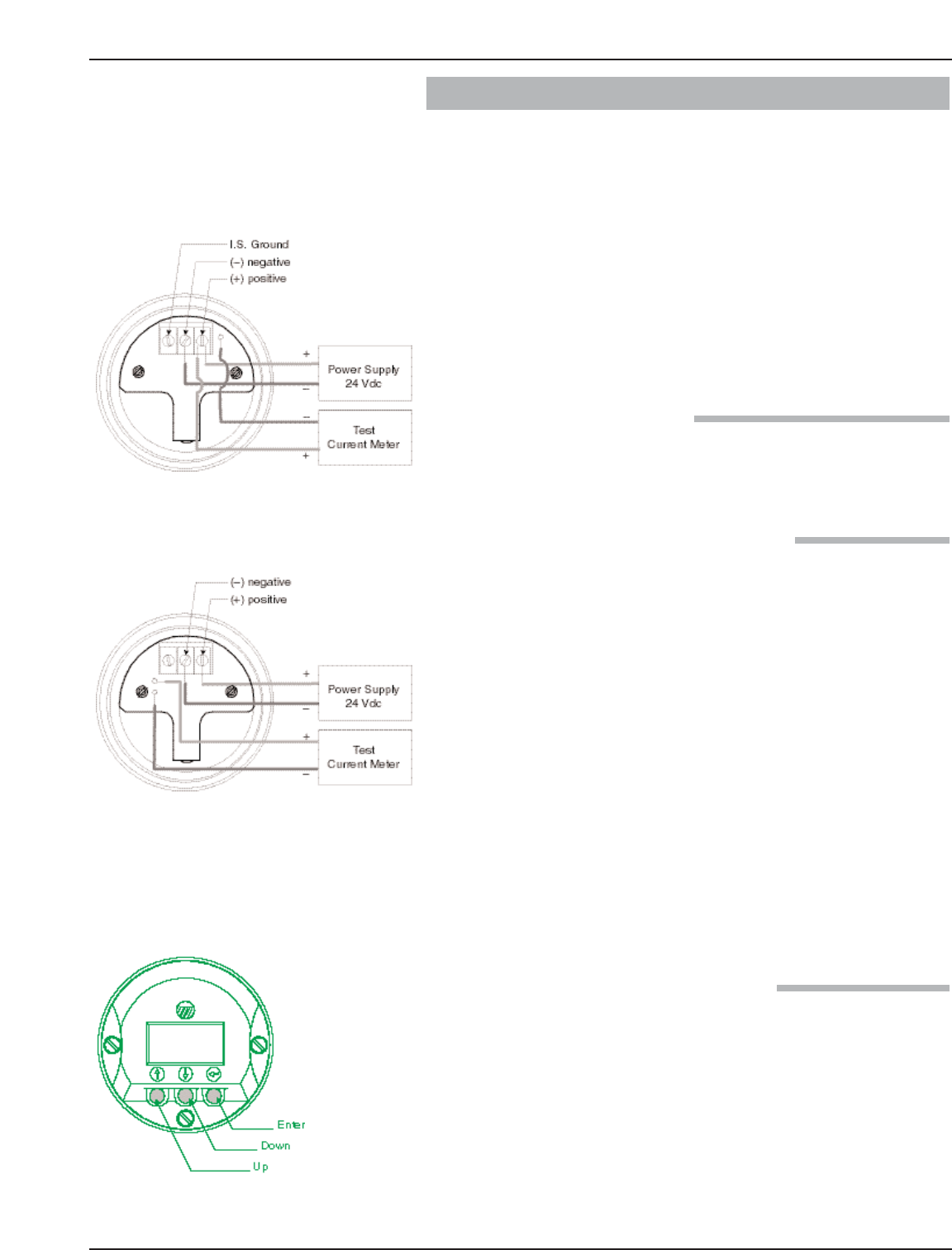
1.6.2 Setting Up for Shop Configuration
The Through-Air Radar transmitter can be configured at a
test bench by connecting a 24 VDC power supply directly
to the transmitter terminals. The connections are illustrated
in the accompanying diagrams. An optional digital multi-
meter is shown if current measurements are desired.
1. When using a HART communicator for configuration, a
minimum 250 Ωline load resistance is required. See the
HART communicator manual for more information.
2. The transmitter can be configured without the antenna,
but disregard error messages due to the unattached
antenna.
3. Through-Air Radar transmitter may indicate a LEVEL
value >0 when disconnected from antenna.
4. After entering the last value, allow 10 seconds before
removing power from the transmitter. This allows the
transmitter to store values.
1.6.3 Transmitter Display and Keypad
The Through-Air Radar transmitter has a liquid-crystal
display (LCD) capable of showing two lines of 8 charac-
ters each. Transmitter measurements and configuration
menu screens are shown on the LCD.
The transmitter default display is the measurement screen.
It cycles every 5 seconds to display LEVEL, %OUTPUT,
Quality, and LOOP information. The transmitter defaults
to this display after 5 minutes if no keystrokes are sensed.
Explosion Proof Model
General Purpose/Intrinsically Safe Model
6

Function in Function in
Arrows Display Mode Configuration Mode
Up and Down Moves forward and backward Increases or decreases the
in the configuration program value displayed or moves to
from one display to another. another choice.
Note: Hold arrow key for
rapid scrolling.
Enter Enters the configuration mode Accepts a value and moves
(noted by an exclamation point to the next step of the
as the last character in the top configuration program.
display line).
1.6.4 Password Protection (Default = 1)
The Through-Air Radar transmitter is password protected
to restrict access to certain portions of the menu structure
that affect the operation of the system. When the proper
password is entered, an exclamation point (!) appears as
the last character of the first line of the display. The pass-
word can be changed to any numerical value up to 255.
The password is required whenever configuration values
are changed.
The default password installed in the transmitter at the
factory is 1. The last step in the configuration menu pro-
vides the option to enter a new password. If 0 is entered as
a password, the transmitter is no longer password protect-
ed and any value in the menu can be altered without
entering a confirming password, except diagnostic values.
Note: If the password is not known, the menu item New Password
displays an encrypted value representing the present pass-
word. Call the factory with this encrypted value to determine
the present password.
1.6.5 Menu: Step-By-Step Procedure
The following table provides a complete explanation of
the software menus displayed by the Through-Air Radar
transmitter. Use this table as a step-by-step guide to con-
figure the transmitter.
The first column presents the menus shown on the trans-
mitter display. The displays are in the order they would
appear if the arrow keys were used to scroll through the
menu. The numbers are not shown on the display. They
are provided as a reference.
The second column provides the actions to take when
configuring the transmitter. Additional information or an
explanation of an action is given in the third column.
The keypad has three arrows used to scroll through the
displays and to calibrate the transmitter – the Up and
Down Arrow ( ) keys and the Enter ( ) key.
➪
➪
➪
7Through-Air Radar Transmitter
➪
➪
➪